EP1798205B1 - Kleinkläranlage mit Ablaufheber - Google Patents
Kleinkläranlage mit Ablaufheber Download PDFInfo
- Publication number
- EP1798205B1 EP1798205B1 EP06025374A EP06025374A EP1798205B1 EP 1798205 B1 EP1798205 B1 EP 1798205B1 EP 06025374 A EP06025374 A EP 06025374A EP 06025374 A EP06025374 A EP 06025374A EP 1798205 B1 EP1798205 B1 EP 1798205B1
- Authority
- EP
- European Patent Office
- Prior art keywords
- outlet
- water level
- small
- aeration basin
- flow direction
- Prior art date
- Legal status (The legal status is an assumption and is not a legal conclusion. Google has not performed a legal analysis and makes no representation as to the accuracy of the status listed.)
- Not-in-force
Links
Images
Classifications
-
- C—CHEMISTRY; METALLURGY
- C02—TREATMENT OF WATER, WASTE WATER, SEWAGE, OR SLUDGE
- C02F—TREATMENT OF WATER, WASTE WATER, SEWAGE, OR SLUDGE
- C02F3/00—Biological treatment of water, waste water, or sewage
- C02F3/02—Aerobic processes
- C02F3/12—Activated sludge processes
- C02F3/1236—Particular type of activated sludge installations
- C02F3/1242—Small compact installations for use in homes, apartment blocks, hotels or the like
- C02F3/1247—Small compact installations for use in homes, apartment blocks, hotels or the like comprising circular tanks with elements, e.g. decanters, aeration basins, in the form of segments, crowns or sectors
-
- C—CHEMISTRY; METALLURGY
- C02—TREATMENT OF WATER, WASTE WATER, SEWAGE, OR SLUDGE
- C02F—TREATMENT OF WATER, WASTE WATER, SEWAGE, OR SLUDGE
- C02F3/00—Biological treatment of water, waste water, or sewage
- C02F3/02—Aerobic processes
- C02F3/12—Activated sludge processes
- C02F3/22—Activated sludge processes using circulation pipes
- C02F3/223—Activated sludge processes using circulation pipes using "air-lift"
-
- Y—GENERAL TAGGING OF NEW TECHNOLOGICAL DEVELOPMENTS; GENERAL TAGGING OF CROSS-SECTIONAL TECHNOLOGIES SPANNING OVER SEVERAL SECTIONS OF THE IPC; TECHNICAL SUBJECTS COVERED BY FORMER USPC CROSS-REFERENCE ART COLLECTIONS [XRACs] AND DIGESTS
- Y02—TECHNOLOGIES OR APPLICATIONS FOR MITIGATION OR ADAPTATION AGAINST CLIMATE CHANGE
- Y02A—TECHNOLOGIES FOR ADAPTATION TO CLIMATE CHANGE
- Y02A20/00—Water conservation; Efficient water supply; Efficient water use
- Y02A20/20—Controlling water pollution; Waste water treatment
- Y02A20/208—Off-grid powered water treatment
-
- Y—GENERAL TAGGING OF NEW TECHNOLOGICAL DEVELOPMENTS; GENERAL TAGGING OF CROSS-SECTIONAL TECHNOLOGIES SPANNING OVER SEVERAL SECTIONS OF THE IPC; TECHNICAL SUBJECTS COVERED BY FORMER USPC CROSS-REFERENCE ART COLLECTIONS [XRACs] AND DIGESTS
- Y02—TECHNOLOGIES OR APPLICATIONS FOR MITIGATION OR ADAPTATION AGAINST CLIMATE CHANGE
- Y02W—CLIMATE CHANGE MITIGATION TECHNOLOGIES RELATED TO WASTEWATER TREATMENT OR WASTE MANAGEMENT
- Y02W10/00—Technologies for wastewater treatment
- Y02W10/10—Biological treatment of water, waste water, or sewage
Definitions
- the invention relates to a small wastewater treatment plant for clarifying wastewater with an inlet for the wastewater, a sludge storage for preclarification of wastewater, an aeration tank for sequential clarification of the wastewater, a drain for clear water, a feed for supplying the activated sludge tank with wastewater from the sludge storage, as required Drainage for the need-based pumping of clear water formed in the aeration tank in the process, the drain having a first delivery line, which forms a lowest point in the flow direction with a U-bend and downstream of which has a compressed air supply.
- Such fully biological small wastewater treatment plants operate according to a discontinuous process, the so-called. SBR process (sequencing batch reactor). For example, on the DE 201 05 661 U1 . DE 20 2004 019 356 U1 or DE 20 2005 003 588 U1 directed.
- SBR process sequencing batch reactor
- EP 1 566 498 discloses a small wastewater treatment plant with a, arranged after the compressed air supply, backstop in the delivery line.
- the wastewater to be clarified flows through an inlet into a sludge storage tank, which is used for pre-treatment of the wastewater and as a pre-buffer.
- a sludge storage tank which is used for pre-treatment of the wastewater and as a pre-buffer.
- sludge storage settleable substances are retained and stored primary and secondary sludge.
- wastewater is transferred from the sludge storage tank to the aeration tank via a feed in periodically recurring pumping operations.
- a wastewater quantity between a minimum water level and a maximum water level in the aeration tank is processed in each cycle.
- pre-clarified water such as air lift or pump transferred to the aeration tank until the maximum water level is reached in the aeration tank.
- aeration in the aeration tank for example by means of membrane pipe aerators, which are usually intermittently pressurized air and arranged at the bottom of the aeration tank.
- the clear water is withdrawn from the upper area of the aeration tank via the drain. Due to the altitude of the inlet in the air lift the minimum water level is limited in the aeration tank.
- compressed air lifters or mammoth pumps used in these small sewage treatment plants have decisive advantages in use.
- compressed air lifters are essentially maintenance-free and require No electrical contacts in the area of the wastewater treatment plant, which reduces the risk of explosion.
- the object of the invention is therefore to provide in a known SBR small wastewater treatment plant with compressed air lift for the clear water withdrawal arrangements to avoid such water pollution.
- the backstop is provided at the inlet of the first delivery line, wherein the inlet is arranged at the level of a minimum water level in the aeration tank, substantially the entire first delivery line through the backstop of the pulsating through the aeration process, turbulent flow conditions in the aeration tank shielded. An entry of activated sludge particles in the first delivery line of the drainage is thus reliably avoided.
- the first delivery line of the drainage outlet opens into the drain at the level of a maximum emergency water level
- the first delivery line of the drainage lever is immediately an emergency. This means that in case of failure of the drain, for example due to power failure, the water level in the aeration tank can reach the maximum emergency water level. Then, a drain of the excess water via the first delivery line and the drain into the water.
- the inventively provided in the first delivery line backstop is also ensured that at high water levels in the water no ambient water pushes back into the system.
- a sampling container is arranged in the flow direction between drainage and drain.
- a significantly higher backwater level of the water can be achieved before a return to the plant takes place.
- the feed means is a feed lifter with a second conveying line which forms a lowest point in the flow direction with a U-bend and downstream of which a compressed air supply, wherein the inlet opening of the second conveying line at the level of the minimum Water level of the sludge storage is arranged and this area in the sludge storage is shielded from above a maximum water level below the minimum water level of the sludge storage hydraulically closed baffle from the rest of sludge storage can be achieved in a simple configuration that any scum in the sludge storage not by means of Feeder is promoted in the aeration tank.
- the baffle consists of a attached to a wall of the sludge storage Folieabites or Tauchrohrabrough.
- the use of film sections or immersion pipe sections for shielding a portion of a clarifier is basically known.
- the embodiment in conjunction with the feed lifter for the small wastewater treatment plant according to the invention can thus be advantageously achieved a reduction of the scum layer in the aeration tank, so that the risk of contamination in the clear water by scorched floating sludge particles is significantly reduced even at the minimum water level in the aeration tank.
- an emergency drain connected to the sampling vessel upstream of the drain is provided for drainage from the aeration tank in case of failure, sampling of the clear water to be discharged to the water can be achieved at a defined location.
- this takes into account regulatory requirements and, with the interposition of the sampling container, also permits an additional connection of an emergency drain through which outflow from the activated sludge tank from an upper clear water area is possible. It can also drain in an emergency, a substantially purified wastewater, so that the burden on the surrounding water is as low as possible.
- the inlet of the emergency drain can be in an altitude above the minimum water level, so that compared to an emergency drain function on the first delivery line the running water quality is still slightly improved.
- a backstop is arranged in the emergency drain, on the one hand the penetration of activated sludge particles in the emergency drain is prevented and on the other hand a return from the outside water into the activated sludge tank is avoided in the event of a backwater of the water body via the drainage level.
- the backstops are preferably flow-direction-sensitive shut-off valves, in particular equipped with rubber flaps.
- Made of rubber flaps backstops are essentially maintenance-free and resistant to the Kläranlagenmilieu. Any floating particles do not disturb the functioning of the backstop.
- the backstop in the flow direction has a threshold resistance, in particular by elastic tension of the butterfly valves, from which the return valve opens, a certain pressure difference as Schwellwiderstand for opening the backstop in the flow direction is required, so that even at substantially balanced pressure conditions, an inflow or subsidence of activated sludge particles be avoided in the first delivery line or in the emergency flow.
- this additional pressure difference must be overcome with a higher emergency water level in the aeration tank. This should be taken into account in the planning.
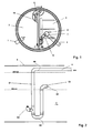
- Fig. 1 is a plan view of a cylindrical concrete container 10 formed with an intermediate wall 11 shown as a two-chamber container.
- the small sewage treatment plant has a feed 1 for domestic wastewater, a sludge storage 2 for preclarification of the wastewater, an aeration tank 3 for the sequential clarification of the wastewater and a drain 4 for clear water.
- a feed means in the form of a feed elevator 5 for supplying the activated sludge tank 3 with waste water from the sludge storage 2 as required, and a drainage jack 6 for pumping clear water formed in the activated sludge tank 3 into the drain 4 are provided.
- the drainage lever 6 consists of a first conveying line 61, which is formed for example of HI or HT pipes.
- the first delivery line 61 has at its lowest point in the in Fig. 2 Installation situation shown in side view in the aeration tank 3 a U-bend 62.
- an air port 63 for connection of a compressed air line, not shown, is arranged by a compressor.
- an inlet opening 64 is arranged at the upstream end of the first delivery line 61.
- the inlet opening 64 is disposed at the level of the minimum water level of the aeration tank WB min , in Fig. 2 is shown in dashed lines.
- a backstop or check valve 65 is arranged in the region of the inlet opening 64.
- the downstream end of the first delivery line 61 leads to the outlet 4.
- the outlet 4 and thus the downstream end of the first delivery line 61 (outlet 66 of the first delivery line 61) above the maximum water level aeration tank WB max is arranged.
- the backstop 65 at the inlet opening 64 of the first delivery line 61 prevents the sinking or ingress of activated sludge particles in that in the first delivery line 61 of the drainage lever 6 clear water from the last clear water outlet is, which forms a back pressure for the backstop and thus closes. This water movements between the water in the first delivery line 61 and the water in the aeration tank 3 can be prevented. Overall, it is thus substantially avoided that activated sludge particles penetrate into the first delivery line 61. Consequently, when activating the drainage lever 6, entrainment of activated sludge and thus water pollution are avoided.
- the clear water withdrawal takes place by means of the drainage lever 6.
- the drainage lever 6 By compressed air to the air connection 63, the drainage lever 6 is activated.
- the compressed air rising in the first delivery line 61 in the branch of the pipeline ascending from the air connection 63 ruptures the clear water located in the first conveying line 61 and conveys it to the outlet 66, which merges into the outlet 4.
- Clear water flows from the aeration tank into the inlet opening 64.
- the backstop 65 opens.
- the height of the outlet 66 is chosen so that at the maximum water level of the aeration tank WB max self-emptying via the first delivery line 61 is not possible.
- the first delivery line 61 simultaneously fulfills an emergency overflow function. As soon as the dot-dashed water level emergency WN is reached, excess water flows via the first delivery line 61 into the outlet 4.
- the backstop 65 thus fulfills a dual function.
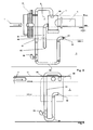
- a drainage lever 6 is shown with a downstream sampling container 7.
- Functionally identical components in comparison to the previously described embodiment are designated by the same reference numerals.
- the drainage lever 6 in turn has a first delivery line 61, which, however, opens with its downstream end as outlet 66 above the sampling container 7. Furthermore, an emergency drain 8 is connected to the sampling container 7, which has a submerged in the aeration tank 3 pipe section 81.
- the pipe section 81 has at its lower end an inlet opening 82 which is positioned approximately at the level of the minimum water level aeration tank WB min .
- a backstop 83 is arranged in the manner of a check valve. From the sampling container 7, the here conveyed clear water is supplied via drain 4 to the body of water.
- the emergency drain 8 is used only in case of failure of the drainage lever 6 to limit a maximum emergency water level WN. Once the water level WN is reached, the substantially clarified water flows from the surrounding area of inlet opening 82 via pipe section 81 through backstop 83 in the sampling container 7 and further through the drain 4 into the water. Although the usual complete purification cycle is not complied with in this emergency drain function, the additional water pollution is nevertheless considerably lower than if the plant were overflowing in an uncontrolled manner.
- the backstop 83 in the emergency drain 8 obstructs a return flow of water from the drain 4 into the aeration tank 3, which is conceivable in an excessively high water level of the water in the drain 4.
- Fig. 3 is the defined by the altitude of the upper edge of the sampling vessel 7 maximum backwater height R max shown. In the case of a sampling container 7 sealed at the top, this backflow height could still be increased to the U-arc height of the first delivery line 61.
- a feed elevator 5 is shown in a side view of the sludge storage 2 in front of the partition 11 of the container 10.
- the loading elevator 5 consists of a second delivery line 51, which is formed at a lowest point with a U-bend 52 and downstream from the U-bend 52 has an air port 53. At this air connection 53, a compressed air line, not shown, for supplying compressed air to the second delivery line 51 is provided.
- an inlet opening 54 is arranged at the level of the minimum water level of the sludge reservoir WS min .
- This inlet opening 54 is arranged in a hydraulically horizontally separated by a baffle 55 area.
- the baffle 55 may be formed, for example, from a film section which is hydraulically attached to the partition wall 11 of the sludge store 2 on both sides of the inlet opening 54, as shown in FIG Fig. 1 also shown in plan view.
Landscapes
- Life Sciences & Earth Sciences (AREA)
- Biodiversity & Conservation Biology (AREA)
- Microbiology (AREA)
- Hydrology & Water Resources (AREA)
- Engineering & Computer Science (AREA)
- Environmental & Geological Engineering (AREA)
- Water Supply & Treatment (AREA)
- Chemical & Material Sciences (AREA)
- Organic Chemistry (AREA)
- Activated Sludge Processes (AREA)
- Sewage (AREA)
Description
- Die Erfindung betrifft eine Kleinkläranlage zum Klären von Abwasser mit einem Zulauf für das Abwasser, einem Schlammspeicher zur Vorklärung des Abwassers, einem Belebungsbecken zur sequentiellen Klärung des Abwassers, einem Ablauf für Klarwasser, einem Beschickungsmittel zum bedarfsweisen Beschicken des Belebungsbeckens mit Abwasser aus dem Schlammspeicher, einem Ablaufheber zum bedarfsweisen Abpumpen von im Belebungsbecken gebildeten Klarwasser in den Ablauf, wobei der Ablaufheber eine erste Förderleitung aufweist, die in Fließrichtung einen tiefsten Punkt mit einem U-Bogen bildet und stromabwärtig davon eine Druckluftzufuhr aufweist.
- Derartige vollbiologische Kleinkläranlagen arbeiten nach einem diskontinuierlichen Verfahren, dem sog. SBR-Verfahren (sequencing batch reactor). Beispielsweise wird auf die
DE 201 05 661 U1 ,DE 20 2004 019 356 U1 oderDE 20 2005 003 588 U1 verwiesen. - Dokument
EP 1 566 498 offenbart eine kleinkläranlage mit einer, nach der Druckluftzufuhr angeordneten, Rücklaufsperre in der Förderleitung. - Insbesondere handelt es sich um eine Kläranlage für häusliche Abwasser, die aus wenigstens zwei Stufen besteht. Das zu klärende Abwasser läuft über einen Zulauf in einen Schlammspeicher, der zur Vorklärung des Abwassers und als Vorpuffer dient. In dem Schlammspeicher werden absetzbare Stoffe zurückgehalten und Primär- und Sekundärschlamm gespeichert. Vom Schlammspeicher wird über ein Beschickungsmittel in periodisch wiederkehrenden Pumpvorgängen Abwasser aus dem Schlammspeicher in das Belebungsbecken überführt.
- Bei dieser chargenweisen Bearbeitung wird in einem Zyklus jeweils eine Abwassermenge zwischen einem minimalen Wasserstand und einem maximalen Wasserstand im Belebungsbecken verarbeitet. Bei der Beschickung wird vorgeklärtes Wasser mit dem Beschickungsmittel, beispielsweise Druckluftheber oder Pumpe in das Belebungsbecken überführt, bis der maximale Wasserstand im Belebungsbecken erreicht ist.
- Nachfolgend folgt eine Belüftung im Belebungsbecken, zum Beispiel mittels Membranrohrbelüfter, die meist intermittierend Druckluft beaufschlagt werden und am Boden des Belebungsbeckens angeordnet sind.
- Nach der Belüftung erfolgt eine Absetzphase, in der der im Belebungsbecken durch die Belüftung verwirbelte Belebtschlamm sich durch Sedimentation absetzen kann. In der Folge bildet sich im oberen Bereich des Belebungsbeckens eine Klarwasserzone und am Boden eine Schlammschicht.
- Nachfolgend wird das Klarwasser aus dem oberen Bereich des Belebungsbeckens über den Ablaufheber abgezogen. Durch die Höhenlage des Einlaufs in den Druckluftheber wird der minimale Wasserstand im Belebungsbecken begrenzt.
- Wenn das Klarwasser abgeführt ist, wird überschüssiger Belebtschlamm aus dem Belebungsbecken mit einem weiteren Fördermittel, meist ebenfalls Druckluftheber, in den Schlammspeicher zurückgefördert.
- Bei derartigen Anlagen werden meist vier Zyklen pro Tag durchgeführt.
- Die bei diesen Kleinkläranlagen verwendeten Druckluftheber oder auch Mammutpumpen genannt, haben entscheidende Nutzungsvorteile. Unter anderem sind Druckluftheber im wesentlichen wartungsfrei und benötigen keine elektrischen Kontakte im Bereich der Kläranlage, womit eine etwaige Explosionsgefahr gemindert ist.
- Nachteilig ist jedoch, dass während der Belüftungsphase Belebtschlamm in die Förderleitung des Ablaufhebers sinken und am Beginn des Klarabwasserabzugs dieser Belebtschlamm als Schmutzfracht in den Ablauf gelangen kann. Dies bedeutet eine unerwünschte Verunreinigung des nachfolgenden Gewässers.
- Aufgabe der Erfindung ist es daher, bei einer bekannten SBR-Kleinkläranlage mit Druckluftheber für den Klarwasserabzug Vorkehrungen vorzusehen, um derartige Gewässerbelastungen zu vermeiden.
- Gelöst wird diese Aufgabe mit einer Kleinkläranlage nach Anspruch 1. Dadurch, dass in Fließrichtung vor der Druckluftzufuhr in der ersten Förderleitung eine Rücklaufsperre angeordnet ist, wird ein unerwünschtes Absinken von Belebtschlamm während der Belüftungsphase in die erste Förderleitung weitestgehend vermieden. Denn durch die erfindungsgemäße Rücklaufsperre wird nach dem letzten Klarwasserabzug vom vorhergehenden Zyklus eine Restwassersäule in der ersten Förderleitung gehalten, die das Rückschlagventil verschließt. Somit können aufgrund des Belüftungsvorgangs pulsierende Wasserstandsänderungen nicht in die erste Förderleitung des Ablaufhebers übertragen werden und keine Belebtschlammpartikel mitgerissen werden.
- Wenn die Rücklaufsperre am Einlauf der ersten Förderleitung vorgesehen ist, wobei der Einlauf auf Höhe eines minimalen Wasserstandes im Belebungsbecken angeordnet ist, wird im wesentlichen die gesamte erste Förderleitung durch die Rücklaufsperre von dem durch den Belüftungsvorgang pulsierenden, turbulenten Strömungsverhältnissen in dem Belebungsbecken abgeschirmt. Ein Eintrag von Belebtschlammpartikeln in die erste Förderleitung des Ablaufhebers wird somit sicher vermieden.
- Dadurch, dass die erste Förderleitung des Ablaufhebers in den Ablauf auf Höhe eines maximalen Notfallwasserstandes mündet, wird die erste Förderleitung des Ablaufhebers unmittelbar zu einem Notablauf. Das heißt, dass bei einem Ausfall des Ablaufhebers, beispielsweise durch Stromausfall, der Wasserstand im Belebungsbecken maximal den Notfallwasserstand erreichen kann. Dann erfolgt ein Ablaufen des überschüssigen Wassers über die erste Förderleitung und den Ablauf in das Gewässer. Durch die erfindungsgemäß in der ersten Förderleitung vorgesehene Rücklaufsperre wird zudem sichergestellt, dass bei hohen Wasserständen im Gewässer kein Umgebungswasser in die Anlage zurückdrückt.
- Bevorzugt ist in Strömungsrichtung zwischen Ablaufheber und Ablauf ein Probenahmebehälter angeordnet. Je nach Ausbildung des Probenahmebehälters und der Ablaufführung kann ein erheblich höherer Rückstauwasserstand des Gewässers erreicht werden, bevor ein Rücklauf in die Anlage erfolgt. Selbstverständlich ist bei dieser Ausgestaltung nicht mehr sichergestellt, dass bei einem Gewässerrückstau über dem Notfallwasserstand noch Klarwasser über den Ablaufheber gegen den äußeren Wasserdruck abgefördert werden kann. Ggf. müsste bei einem zu hohen Rückstauwasserstand des äußeren Gewässers auch die Beschickung der Kleinkläranlage reduziert oder eingestellt werden. Gleichwohl erhöht die eingebaute Rücklaufsperre die unmittelbare Gefahr eines Überlaufs der Kleinkläranlage aufgrund eines Gewässerrückstaus.
- Dadurch, dass das Beschickungsmittel ein Beschickungsheber mit einer zweiten Förderleitung ist, die in Fließrichtung einen tiefsten Punkt mit einem U-Bogen bildet und stromabwärtig davon eine Druckluftzufuhr aufweist, wobei die Einlauföffnung der zweiten Förderleitung auf Höhe des minimalen Wasserstandes des Schlammspeichers angeordnet ist und dieser Bereich im Schlammspeicher durch eine von oberhalb eines maximalen Wasserstandes bis unterhalb des minimalen Wasserstandes des Schlammspeichers hydraulisch geschlossen ausgebildete Tauchwand vom übrigen Schlammspeicher abgeschirmt ist, kann in einfacher Ausgestaltung erreicht werden, dass eine etwaige Schwimmschlammschicht im Schlammspeicher nicht mittels des Beschickungshebers in das Belebungsbecken gefördert wird.
- Bevorzugt besteht die Tauchwand aus einem an einer Wand des Schlammspeichers befestigten Folieabschnitt oder Tauchrohrabschnitt. Dabei ist die Anwendung von Folienabschnitten oder Tauchrohrabschnitten zur Abschirmung eines Teilbereiches eines Klärbeckens grundsätzlich bekannt. Bei der Ausgestaltung in Verbindung mit dem Beschickungsheber für die erfindungsgemäße Kleinkläranlage kann damit vorteilhaft eine Verringerung der Schwimmschlammschicht im Belebungsbecken erreicht werden, so dass die Gefahr einer Schmutzfracht im Klarwasser durch angesogene Schwimmschlammpartikel auch beim minimalen Wasserstand im Belebungsbecken deutlich verringert ist.
- Wenn ein am in Strömungsrichtung vor dem Ablauf angeordneter Probenahmebehälter angeschlossener Notablauf für einen Abfluss aus dem Belebungsbecken im Störungsfall vorgesehen ist, kann eine Probenahme des an das Gewässer abzugebenden Klarwassers an einer definierten Stelle erreicht werden. Dies berücksichtigt einerseits behördliche Auflagen und erlaubt durch die Zwischenschaltung des Probenahmebehälters auch einen zusätzlichen Anschluss eines Notablaufs, durch den der Abfluss aus dem Belebungsbecken von einem oberen Klarwasserbereich möglich ist. Es kann dabei auch im Notfall ein im wesentlichen gereinigtes Abwasser abfließen, so dass die Belastung des Umgebungsgewässers möglichst gering ist. Dabei kann der Einlauf des Notablaufs in eine Höhenlage oberhalb des minimalen Wasserstandes liegen, so dass gegenüber einer Notablauffunktion über die erste Förderleitung die ablaufende Wasserqualität noch geringfügig verbessert wird.
- Dadurch, dass im Notablauf eine Rücklaufsperre angeordnet ist, wird einerseits ein Eindringen von Belebtschlammpartikeln im Notablauf verhindert und andererseits ein Rücklauf vom Außengewässer in das Belebungsbecken bei einem Rückstau des Gewässers über die Ablaufebene vermieden.
- Bevorzugt sind die Rücklaufsperren strömungsrichtungssensitive Absperrklappen, insbesondere mit Gummiklappen ausgerüstet. Aus Gummiklappen gebildete Rücklaufsperren sind im wesentlichen wartungsfrei und resistent gegenüber dem Kläranlagenmilieu. Etwaige Schwebteilchen stören die Funktionsfähigkeit der Rücklaufsperre nicht.
- Wenn die Rücklaufsperre in Durchströmungsrichtung einen Schwellwiderstand aufweist, insbesondere durch elastische Verspannung der Absperrklappen, ab dem die Rücklaufklappe öffnet, wird eine gewisse Druckdifferenz als Schwellwiderstand zur Öffnung der Rücklaufsperre in Durchströmungsrichtung erforderlich, so dass auch bei im wesentlichen ausgeglichenen Druckverhältnissen ein Einströmen oder Einsinken von Belebtschlammpartikeln in die erste Förderleitung bzw. in den Notablauf vermieden werden. Für die Notablauffunktion muss diese zusätzliche Druckdifferenz mit einem höheren Notfallwasserstand im Belebungsbecken überwunden werden. Dies ist bei der Planung zu berücksichtigen.
- Nachfolgend werden zwei Ausführungsbeispiele der Erfindung anhand der beiliegenden Zeichnung beschrieben.
- Darin zeigt:
- Fig. 1
- eine Kleinkläranlage bestehend aus einem Zweikammerbetonbehälter in Draufsicht,
- Fig. 2
- einen Ablaufheber in Einbausituation in einem Belebungsbecken in Seitenansicht in einem ersten Ausführungsbeispiel,
- Fig. 3
- einen Ablaufheber in Einbausituation in einem Belebungsbecken in Seitenansicht in einem zweiten Ausführungsbeispiel und
- Fig. 4
- einen Beschickungsheber in Einbausituation in einem Schlammspeicher in Seitenansicht.
- In
Fig. 1 ist in Draufsicht ein zylindrischer Betonbehälter 10 ausgebildet mit einer Zwischenwand 11 als Zweikammerbehälter dargestellt. Die Kleinkläranlage weist einen Zulauf 1 für das häusliche Abwasser, einen Schlammspeicher 2 zur Vorklärung des Abwassers, ein Belebungsbecken 3 zur sequentiellen Klärung des Abwassers und einen Ablauf 4 für Klarwasser auf. Ferner ist ein Beschickungsmittel in Form eines Beschickungshebers 5 zum bedarfsweisen Beschicken des Belebungsbeckens 3 mit Abwasser aus dem Schlammspeicher 2 sowie ein Ablaufheber 6 zum bedarfsweisen Abpumpen von im Belebungsbecken 3 gebildeten Klarwasser in den Ablauf 4 vorgesehen. - Wie in
Fig. 2 in einer ersten Ausführungsform dargestellt, besteht der Ablaufheber 6 aus einer ersten Förderleitung 61, die beispielsweise aus HI- oder HT-Rohren gebildet ist. Die erste Förderleitung 61 weist an seinem tiefsten Punkt in der inFig. 2 in Seitenansicht dargestellten Einbausituation im Belebungsbecken 3 einen U-Bogen 62 auf. An der stromabwärtigen Seite des U-Bogens 62 ist ein Luftanschluss 63 zum Anschluss einer nicht dargestellten Druckluftleitung von einem Kompressor angeordnet. - Am stromaufwärtigen Ende der ersten Förderleitung 61 ist eine Einlauföffnung 64 angeordnet. Die Einlauföffnung 64 ist auf Höhe des minimalen Wasserstandes des Belebungsbeckens WBmin angeordnet, der in
Fig. 2 gestrichelt dargestellt ist. Im Bereich der Einlauföffnung 64 ist eine Rücklaufsperre oder Rückschlagventil 65 angeordnet. - Das stromabwärtige Ende der ersten Förderleitung 61 führt zum Ablauf 4. Um eine unkontrollierte Selbstentleerung zu vermeiden, ist der Ablauf 4 und somit das stromabwärtige Ende der ersten Förderleitung 61 (Auslauf 66 der ersten Förderleitung 61) oberhalb des maximalen Wasserstandes Belebungsbeckens WBmax angeordnet.
- Die Funktionsweise des Ausführungsbeispiels gemäß
Fig. 2 ist wie folgt: - Die Rücklaufsperre 65 an der Einlauföffnung 64 der ersten Förderleitung 61 verhindert das Einsinken bzw. Eindringen von Belebtschlammpartikeln dadurch, dass sich in der ersten Förderleitung 61 des Ablaufhebers 6 Klarwasser vom letzten Klarwasserabzug befindet, das einen Gegendruck für die Rücklaufsperre bildet und sie somit schließt. Damit können Wasserbewegungen zwischen dem Wasser in der ersten Förderleitung 61 und dem Wasser im Belebungsbecken 3 unterbunden werden. Insgesamt wird somit im wesentlichen vermieden, dass Belebtschlammpartikel in die erste Förderleitung 61 eindringen. Folglich wird beim Aktivieren des Ablaufhebers 6 ein Mitführen von Belebtschlamm und damit eine Gewässerverunreinigung vermieden.
- Wenn die Belüftungs- und Absetzphase eines Zykluses der SBR-Kleinkläranlage beendet ist, erfolgt der Klarwasserabzug mittels dem Ablaufheber 6. Durch Druckluftbeaufschlagung an den Luftanschluss 63 wird der Ablaufheber 6 aktiviert. Die in der ersten Förderleitung 61 im vom Luftanschluss 63 aufsteigenden Ast der Rohrleitung aufsteigende Druckluft reisst das sich in der ersten Förderleitung 61 befindliche Klarwasser mit und fördert es zum Auslauf 66, der in den Ablauf 4 übergeht. Klarwasser strömt vom Belebungsbecken in die Einlauföffnung 64 nach. Dabei öffnet sich die Rücklaufsperre 65. Die Höhe des Auslaufs 66 ist so gewählt, dass beim maximalen Wasserstand des Belebungsbeckens WBmax eine Selbstentleerung über die erste Förderleitung 61 nicht möglich ist. Sollte aufgrund eines Störfalls jedoch der Wasserspiegel über den Wasserstand WBmax steigen, erfüllt die erste Förderleitung 61 gleichzeitig eine Notüberlauffunktion. Sobald der strichpunktierte Wasserstand Notfall WN erreicht ist, fließt überschüssiges Wasser über die erste Förderleitung 61 in den Ablauf 4 ab.
- Bei übermäßig hohen Wasserständen im Gewässer und damit einem Rückstau im Ablauf 4 verhindert zudem das Rückschlagventil 65 das Eindringen von Umgebungswasser in die Anlage. Die Rücklaufsperre 65 erfüllt somit eine Doppelfunktion.
- In
Fig. 3 ist ein Ablaufheber 6 mit einem nachgeschalteten Probenahmebehälter 7 dargestellt. Funktionsgleiche Bauteile im Vergleich zum vorher beschriebenen Ausführungsbeispiel sind mit gleichen Bezugszeichen bezeichnet. - Der Ablaufheber 6 weist wiederum eine erste Förderleitung 61 auf, die jedoch mit ihrem stromabwärtigen Ende als Auslauf 66 oberhalb des Probenahmebehälters 7 einmündet. Ferner ist am Probenahmebehälter 7 ein Notablauf 8 angeschlossen, der einen in dem Belebungsbecken 3 eintauchenden Rohrabschnitt 81 aufweist. Der Rohrabschnitt 81 weist an seinem unteren Ende eine Einlauföffnung 82 auf, die etwa auf Höhe des minimalen Wasserstandes Belebungsbecken WBmin positioniert ist. Im Rohrabschnitt 81 ist eine Rücklaufsperre 83 in Art eines Rückschlagventils angeordnet. Vom Probenahmebehälter 7 wird das hierhin beförderte Klarwasser über Ablauf 4 dem Gewässer zugeführt.
- Beim gewöhnlichen Betrieb der Kläranlage wird entsprechend des Klärzykluses ein Klarwasserabzug über Ablaufheber 6 vom maximalen Wasserstand des Belebungsbecken WBmax bis zum minimalen Wasserstand des Belebungsbeckens WBmin durch Druckluftbeaufschlagung des Luftanschlusses 63 des Ablaufhebers 6 bewirkt. Das Klarwasser gelangt dabei über den Probenahmebehälter 7 in den Ablauf 4. Bei Bedarf kann unter dem Auslauf 66 der ersten Förderleitung 61 ein Probenahmebehälter für eine Probenahme gehalten werden.
- Der Notablauf 8 dient lediglich bei Ausfall des Ablaufhebers 6 zur Begrenzung eines maximalen Notfallwasserstandes WN. Sobald der Wasserstand WN erreicht ist, fließt das im wesentlichen geklärte Wasser aus dem Umgebungsbereich von Einlauföffnung 82 über Rohrabschnitt 81 durch Rücklaufsperre 83 in den Probenahmebehälter 7 und weiter durch Ablauf 4 in das Gewässer. Zwar wird bei dieser Notablauffunktion der übliche vollständige Klärzyklus nicht eingehalten, gleichwohl ist die zusätzliche Gewässerbelastung erheblich geringer, als wenn die Anlage unkontrolliert überlaufen würde.
- Als zusätzliche Sicherheitsfunktion versperrt die Rücklaufsperre 83 im Notablauf 8 einen Rückfluss von Wasser aus dem Ablauf 4 in das Belebungsbecken 3, was bei einem übermäßig hohen Wasserstand des Gewässers im Ablauf 4 denkbar ist. In
Fig. 3 ist die durch die Höhenlage der Oberkante des Probenahmebehälters 7 definierte maximale Rückstauhöhe Rmax dargestellt. Bei einem oben abgedichteten Probenahmebehälter 7 könnte diese Rückstauhöhe noch auf die U-Bogenhöhe der ersten Förderleitung 61 erhöht werden. - In
Fig. 4 ist ein Beschickungsheber 5 in einer Seitenansicht vom Schlammspeicher 2 vor der Trennwand 11 des Behälters 10 dargestellt. Der Beschickungsbeheber 5 besteht aus einer zweiten Förderleitung 51, die in einem tiefsten Punkt mit einem U-Bogen 52 ausgebildet ist und stromabwärtig vom U-Bogen 52 einen Luftanschluss 53 aufweist. An diesem Luftanschluss 53 ist eine nicht dargestellte Druckluftleitung zur Druckluftbeaufschlagung der zweiten Förderleitung 51 vorgesehen. - Am stromaufwärtigen Ende der ersten Förderleitung 51 ist eine Einlauföffnung 54 auf Höhe des minimalen Wasserstandes des Schlammspeichers WSmin angeordnet. Diese Einlauföffnung 54 ist in einem hydraulisch horizontal durch eine Tauchwand 55 abgetrennten Bereich angeordnet. Die Tauchwand 55 kann beispielsweise aus einem Folienabschnitt gebildet sein, der an die Trennwand 11 des Schlammspeichers 2 beidseitig der Einlauföffnung 54 hydraulisch dicht befestigt ist, wie dies in
Fig. 1 auch in der Draufsicht dargestellt ist. - Beim bestimmungsgemäßen Betrieb erfolgt ein Wasseraustausch nur über den unten offenen Querschnitt zwischen dem Bereich innerhalb der Tauchwand 55 und dem restlichen Bereich des Schlammspeichers 2. Beim Betätigen des Beschichtungshebers 5 wird somit insbesondere beim Erreichen des minimalen Wasserstandes des Schlammspeichers WSmin verhindert, dass Schwimmschlammschichten, die auf dem Wasserspiegel im Schlammspeicher 2 aufschwimmen, im zu großen Umfang von dem Beschickungsheber 5 in das Belebungsbecken 3 gefördert werden.
- In Verbindung mit der erfindungsgemäß vorgesehenen Rücklaufsperre 65 an der Einlauföffnung 64 des Ablaufhebers 6 wird somit die Beaufschlagung des Belebungsbeckens 3 mit Schwimmschlammpartikeln weitestgehend vermieden, so dass diese nicht beim Klarwasserabzug über den Ablaufheber 6 unmittelbar in den Ablauf 4 und damit in das nachfolgende Gewässer gelangen können.
-
- 1
- Zulauf
- 10
- Betonbehälter
- 11
- Zwischenwand
- 2
- Schlammspeicher
- 3
- Belebungsbecken
- 4
- Ablauf
- 5
- Beschickungsmittel
- 51
- zweite Förderleitung
- 52
- U-Bogen
- 53
- Luftanschluss
- 54
- Einlauföffnung
- 55
- Tauchwand
- 6
- Ablaufheber
- 61
- erste Förderleitung
- 62
- U-Bogen
- 63
- Luftanschluss
- 64
- Einlauföffnung, Einlauf
- 65
- Rücklaufsperre, Rückschlagventil
- 66
- Auslauf
- 7
- Probenahmebehälter
- 8
- Notablauf
- 81
- Rohrabschnitt
- 82
- Einlauföffnung
- 83
- Rücklaufsperre, Rückschlagventil
- WBmax
- maximaler Wasserstand Belebungsbecken
- WBmin
- minimaler Wasserstand Belebungsbecken
- WSmax
- maximaler Wasserstand Schlammspeicher
- WSmin
- minimaler Wasserstand Schlammspeicher
- WN
- Wasserstand Notfall
- Rmax
- maximale Rückstauhöhe
Claims (10)
- Kleinkläranlage zum Klären von Abwasser mit- einem Zulauf (1) für das Abwasser,- einem Schlammspeicher (2) zur Vorklärung des Abwassers,- einem Belebungsbecken (3) zur sequentiellen Klärung des Abwassers,- einem Ablauf (4) für Klarwasser,- einem Beschickungsmittel (5) zum bedarfsweisen Beschicken des Belebungsbeckens (3) mit Abwasser aus dem Schlammspeicher (2),- einem Ablaufheber (6) zum bedarfsweisen Abpumpen von im Belebungsbecken (3) gebildeten Klarwasser in den Ablauf (4),wobei der Ablaufheber (6) eine erste Förderleitung (61) aufweist, die in Fließrichtung einen tiefsten Punkt mit einem U-Bogen (62) bildet und stromabwärtig davon eine Druckluftzufuhr (63) aufweist,
dadurch gekennzeichnet, dass in Fließrichtung vor der Druckluftzufuhr (63) in der ersten Förderleitung (61) eine Rücklaufsperre (65) angeordnet ist. - Kleinkläranlage nach Anspruch 1, dadurch gekennzeichnet, dass die Rücklaufsperre (65) am Einlauf (64) der ersten Förderleitung (61) vorgesehen ist, wobei der Einlauf (64) auf Höhe eines minimalen Wasserstandes (WBmin) im Belebungsbecken (3) angeordnet ist.
- Kleinkläranlage nach Anspruch 1 oder 2, dadurch gekennzeichnet, dass die erste Förderleitung (61) des Ablaufhebers (6) in den Ablauf (4) auf Höhe eines maximalen Notfallwasserstandes (WN) mündet.
- Kleinkläranlage nach Anspruch 1, 2 oder 3, dadurch gekennzeichnet, dass in Strömungsrichtung zwischen Ablaufheber (6) und Ablauf (4) ein Probenahmebehälter (7) angeordnet ist.
- Kleinkläranlage nach einem der vorangehenden Ansprüche, dadurch gekennzeichnet, dass das Beschickungsmittel (5) ein Beschickungsheber mit einer zweiten Förderleitung (51) ist, die in Fließrichtung einen tiefsten Punkt mit einem U-Bogen (52) bildet und stromabwärtig davon eine Druckluftzufuhr (53) aufweist, wobei die Einlauföffnung (54) der zweiten Förderleitung (51) auf Höhe des minimalen Wasserstandes (WSmin) des Schlammspeichers (2) angeordnet ist und dieser Bereich im Schlammspeicher (2) durch eine von oberhalb eines maximalen Wasserstandes (WSmax) bis unterhalb des minimalen Wasserstandes (WSmin) des Schlammspeichers (2) hydraulisch geschlossen ausgebildete Tauchwand (55) vom übrigen Schlammspeicher (2) abgeschirmt ist.
- Kleinkläranlage nach Anspruch 5, dadurch gekennzeichnet, dass die Tauchwand (55) aus einem an einer Wand (11) des Schlammspeichers (2) befestigten Folieabschnitt oder Tauchrohrabschnitt besteht.
- Kleinkläranlage nach einem der vorangehenden Ansprüche, dadurch gekennzeichnet, dass ein am in Strömungsrichtung vor dem Ablauf (4) angeordneter Probenahmebehälter (7) angeschlossener Notablauf (8) für einen Abfluss aus dem Belebungsbecken (3) im Störungsfall vorgesehen ist.
- Kleinkläranlage nach Anspruch 7, dadurch gekennzeichnet, dass im Notablauf (8) eine Rücklaufsperre (83) angeordnet ist.
- Kleinkläranlage nach einem der vorangehenden Ansprüche, dadurch gekennzeichnet, dass die Rücklaufsperre (65, 83) eine strömungsrichtungssensitive Absperrklappe, bevorzugt mit Gummiklappen, ist.
- Kleinkläranlage nach Anspruch 9, dadurch gekennzeichnet, dass die Rücklaufsperre (65, 83) in Durchströmungsrichtung einen Schwellwiderstand aufweist, insbesondere durch elastische Verspannung der Absperrklappen, ab dem die Rücklaufklappe öffnet.
Applications Claiming Priority (1)
| Application Number | Priority Date | Filing Date | Title |
|---|---|---|---|
| DE202005019918U DE202005019918U1 (de) | 2005-12-19 | 2005-12-19 | Kleinkläranlage mit Ablaufheber |
Publications (2)
| Publication Number | Publication Date |
|---|---|
| EP1798205A1 EP1798205A1 (de) | 2007-06-20 |
| EP1798205B1 true EP1798205B1 (de) | 2009-02-11 |
Family
ID=37513914
Family Applications (1)
| Application Number | Title | Priority Date | Filing Date |
|---|---|---|---|
| EP06025374A Not-in-force EP1798205B1 (de) | 2005-12-19 | 2006-12-08 | Kleinkläranlage mit Ablaufheber |
Country Status (4)
| Country | Link |
|---|---|
| EP (1) | EP1798205B1 (de) |
| AT (1) | ATE422486T1 (de) |
| DE (2) | DE202005019918U1 (de) |
| ES (1) | ES2321128T3 (de) |
Families Citing this family (16)
| Publication number | Priority date | Publication date | Assignee | Title |
|---|---|---|---|---|
| DE102006052965A1 (de) * | 2006-11-08 | 2008-05-29 | Kordes Kld Wasser- Und Abwassersysteme Gmbh | Verfahren zur Klärung von Abwasser in einer Kleinkläranlage sowie eine Kleinkläranlage |
| DE202007000048U1 (de) * | 2007-11-22 | 2008-01-17 | Solid-Clair Watersystems Gmbh & Co. Kg | Kompakte Heberanordnung |
| DE202010014736U1 (de) | 2010-10-28 | 2011-01-20 | PRÄDEL, Birgit | Klarwasser-Druckluftheber für biologische Kläranlagen |
| DE102010049709B3 (de) | 2010-10-28 | 2012-04-05 | Birgit Prädel | Klarwasser-Druckluftheber für biologische Kläranlagen, Verfahren zu dessen Betrieb und dessen Verwendung |
| DE102011122695B4 (de) | 2011-12-23 | 2013-09-05 | Birgit Prädel | Klarwasser- Druckluftheber für biologische Kläranlagen und Verfahren zu dessen Betrieb |
| DE102012024832A1 (de) * | 2012-12-17 | 2014-06-18 | Klaro Gmbh | Wasserhebevorrichtung für gereinigtes Wasser aus einem Reinigungsbecken |
| DE102013017741A1 (de) | 2013-10-28 | 2015-04-30 | Reinhard Boller | Verfahren und Vorrichtung zur Optimierung einer Kleinkläranlage oder kleinen Kläranlage durch Vermeidung oder Verminderung des Austrages von Schlammpartikeln aus dem Druckluftheber für den Klarwasserabzug |
| DE102014015488B4 (de) | 2014-10-17 | 2017-05-11 | Birgit Prädel | Zweifunktionaler Druckluftheber für biologische Kläranlagen, Verfahren zu dessen Betrieb und dessen Verwendung |
| EP3135637A1 (de) * | 2015-08-31 | 2017-03-01 | KLARO GmbH | Sbr-kläranlage |
| DE202015105725U1 (de) | 2015-10-28 | 2015-11-10 | Birgit Prädel | Dreifunktionaler Druckluftheber für biologische Kläranlagen |
| CN105413506B (zh) * | 2015-11-27 | 2024-06-18 | 张旭 | 气液混合系统防回水装置 |
| DE202016100805U1 (de) | 2016-02-17 | 2016-03-03 | Birgit Prädel | Druckluftheber als höhenverstellbarer Klarwasserheber mit einer aktiven Rückspülfunktion |
| DE102016117462B3 (de) | 2016-09-16 | 2018-04-19 | Hubert Prädel | Druckluftklarwasserheber mit Verunreinigungsschutz |
| DE202016105173U1 (de) | 2016-09-16 | 2016-10-11 | Hubert Prädel | Druckluftklarwasserheber mit Verunreinigungsschutz |
| DE102017001738B4 (de) | 2017-02-22 | 2019-02-21 | Klaro Gmbh | Wasserhebevorrichtung mit einer Abscheidevorrichtung |
| CN121247926A (zh) * | 2025-12-05 | 2026-01-02 | 福建中科三净环保股份有限公司 | 农村简易式污水处理罐 |
Family Cites Families (10)
| Publication number | Priority date | Publication date | Assignee | Title |
|---|---|---|---|---|
| CA2041329C (en) * | 1991-04-26 | 1994-05-24 | Brian H. Topnik | Sequencing batch reactors |
| DE19538387A1 (de) * | 1995-10-14 | 1997-04-24 | Theodor Zink Gmbh | Verfahren und Vorrichtung zur Umrüstung einer Mehrkammer-Kleinkläranlage |
| EP0893413B1 (de) * | 1997-07-17 | 2004-01-21 | J.H. & Wilhelm Finger GmbH & Co. KG | Verfahren und Vorrichtung zur biologischen Behandlung von Flüssigkeiten, insbesondere zur vollbiologischen Klärung von Abwasser |
| DE19917463C2 (de) * | 1999-04-17 | 2001-04-19 | Biovac Abwasserreinigungs Gmbh | Dreikammer-Kleinkläranlage zur batch-weisen biologischen Abwasserreinigung |
| DE10048309C2 (de) * | 2000-09-29 | 2003-02-20 | Envicon Klaertechnik Gmbh & Co | Kleinkläranlage |
| DE20105661U1 (de) * | 2001-03-30 | 2001-08-30 | Zapf GmbH, 95448 Bayreuth | Kleinkläranlage |
| DE202004019356U1 (de) * | 2003-12-23 | 2005-05-04 | Uponor Innovation Ab | Kleinkläranlage |
| DE602004000905T2 (de) * | 2004-02-06 | 2006-09-14 | Uponor Innovation Ab | Verfahren zum Heben von Abwasser und Abwasserpumpe |
| DE202004001854U1 (de) * | 2004-02-06 | 2004-07-15 | Wissmann Elektronik Gmbh | Kleinkläranlage |
| DE202005003588U1 (de) * | 2005-03-05 | 2005-05-25 | Kordes Kld Wasser- Und Abwassersysteme Gmbh | Kleinkläranlage |
-
2005
- 2005-12-19 DE DE202005019918U patent/DE202005019918U1/de not_active Expired - Lifetime
-
2006
- 2006-12-08 ES ES06025374T patent/ES2321128T3/es active Active
- 2006-12-08 EP EP06025374A patent/EP1798205B1/de not_active Not-in-force
- 2006-12-08 DE DE200650002804 patent/DE502006002804D1/de active Active
- 2006-12-08 AT AT06025374T patent/ATE422486T1/de active
Also Published As
| Publication number | Publication date |
|---|---|
| EP1798205A1 (de) | 2007-06-20 |
| DE202005019918U1 (de) | 2006-11-23 |
| ES2321128T3 (es) | 2009-06-02 |
| ATE422486T1 (de) | 2009-02-15 |
| DE502006002804D1 (de) | 2009-03-26 |
Similar Documents
| Publication | Publication Date | Title |
|---|---|---|
| EP1798205B1 (de) | Kleinkläranlage mit Ablaufheber | |
| EP2641876B1 (de) | Biologische Klärvorrichtung | |
| EP2743515B1 (de) | Wasserhebevorrichtung für gereinigtes Wasser aus einem Reinigungsbecken | |
| DE102011122695B4 (de) | Klarwasser- Druckluftheber für biologische Kläranlagen und Verfahren zu dessen Betrieb | |
| EP2660208B1 (de) | Kläranlage mit siphonüberlauf | |
| EP0427213B1 (de) | Anlage zur Reduzierung des Frischwasserbedarfs | |
| WO2012062269A1 (de) | Klarwasser- druckluftheber für biologische kläranlagen, verfahren zu dessen betrieb und dessen verwendung | |
| DE102014015488A1 (de) | Zweifunktionaler Druckluftheber für biologische Kläranlagen, Verfahren zu dessen Betrieb und dessen Verwendung | |
| EP1854766B1 (de) | Verfahren und Vorrichtung zur Behandlung von Abwasser | |
| EP2535317B1 (de) | Biologische Klärvorrichtung | |
| DE202008003062U1 (de) | Biologische Klärvorrichtung | |
| DE202015105725U1 (de) | Dreifunktionaler Druckluftheber für biologische Kläranlagen | |
| AT2014U1 (de) | Biologische kläranlage und verfahren zum betreiben einer solchen | |
| DE19534657C2 (de) | Kleinkläranlage für häusliche Abwässer | |
| DE202005019919U1 (de) | Kleinkläranlage mit Notablauf | |
| DE202008009513U1 (de) | Vorrichtung in Form eines Festbettkörpers | |
| DE102009042292B3 (de) | Vorrichtung und Verfahren zum Abzug von Klarwasser aus einem Klärbecken | |
| DE102016117462B3 (de) | Druckluftklarwasserheber mit Verunreinigungsschutz | |
| DE102012110773B4 (de) | Pumpstation und Verfahren zum Abpumpen von Abwasser | |
| EP1591424B1 (de) | Biologische Klärvorrichtung | |
| EP1588987B1 (de) | Kläranlage mit konzentrisch angeordneten Becken | |
| DE202010009084U1 (de) | Biologische Klärvorrichtung | |
| DE202010014736U1 (de) | Klarwasser-Druckluftheber für biologische Kläranlagen | |
| DE202016105173U1 (de) | Druckluftklarwasserheber mit Verunreinigungsschutz | |
| DE9412973U1 (de) | Abscheideanlage für mit Leichtstoffen verschmutzte Abwässer |
Legal Events
| Date | Code | Title | Description |
|---|---|---|---|
| PUAI | Public reference made under article 153(3) epc to a published international application that has entered the european phase |
Free format text: ORIGINAL CODE: 0009012 |
|
| AK | Designated contracting states |
Kind code of ref document: A1 Designated state(s): AT BE BG CH CY CZ DE DK EE ES FI FR GB GR HU IE IS IT LI LT LU LV MC NL PL PT RO SE SI SK TR |
|
| AX | Request for extension of the european patent |
Extension state: AL BA HR MK YU |
|
| 17P | Request for examination filed |
Effective date: 20071121 |
|
| AKX | Designation fees paid |
Designated state(s): AT BE BG CH CY CZ DE DK EE ES FI FR GB GR HU IE IS IT LI LT LU LV MC NL PL PT RO SE SI SK TR |
|
| GRAP | Despatch of communication of intention to grant a patent |
Free format text: ORIGINAL CODE: EPIDOSNIGR1 |
|
| RTI1 | Title (correction) |
Free format text: SMALL SCALE WATER PURIFICATION PLANT WITH OUTFLOW SIPHON |
|
| GRAS | Grant fee paid |
Free format text: ORIGINAL CODE: EPIDOSNIGR3 |
|
| GRAS | Grant fee paid |
Free format text: ORIGINAL CODE: EPIDOSNIGR3 |
|
| GRAA | (expected) grant |
Free format text: ORIGINAL CODE: 0009210 |
|
| AK | Designated contracting states |
Kind code of ref document: B1 Designated state(s): AT BE BG CH CY CZ DE DK EE ES FI FR GB GR HU IE IS IT LI LT LU LV MC NL PL PT RO SE SI SK TR |
|
| REG | Reference to a national code |
Ref country code: GB Ref legal event code: FG4D Free format text: NOT ENGLISH |
|
| REG | Reference to a national code |
Ref country code: CH Ref legal event code: EP |
|
| REG | Reference to a national code |
Ref country code: IE Ref legal event code: FG4D Free format text: LANGUAGE OF EP DOCUMENT: GERMAN |
|
| REF | Corresponds to: |
Ref document number: 502006002804 Country of ref document: DE Date of ref document: 20090326 Kind code of ref document: P |
|
| REG | Reference to a national code |
Ref country code: CH Ref legal event code: NV Representative=s name: PATENTANWAELTE SCHAAD, BALASS, MENZL & PARTNER AG |
|
| REG | Reference to a national code |
Ref country code: GR Ref legal event code: EP Ref document number: 20090401186 Country of ref document: GR |
|
| REG | Reference to a national code |
Ref country code: ES Ref legal event code: FG2A Ref document number: 2321128 Country of ref document: ES Kind code of ref document: T3 |
|
| PG25 | Lapsed in a contracting state [announced via postgrant information from national office to epo] |
Ref country code: SI Free format text: LAPSE BECAUSE OF FAILURE TO SUBMIT A TRANSLATION OF THE DESCRIPTION OR TO PAY THE FEE WITHIN THE PRESCRIBED TIME-LIMIT Effective date: 20090211 Ref country code: LT Free format text: LAPSE BECAUSE OF FAILURE TO SUBMIT A TRANSLATION OF THE DESCRIPTION OR TO PAY THE FEE WITHIN THE PRESCRIBED TIME-LIMIT Effective date: 20090211 Ref country code: NL Free format text: LAPSE BECAUSE OF FAILURE TO SUBMIT A TRANSLATION OF THE DESCRIPTION OR TO PAY THE FEE WITHIN THE PRESCRIBED TIME-LIMIT Effective date: 20090211 Ref country code: FI Free format text: LAPSE BECAUSE OF FAILURE TO SUBMIT A TRANSLATION OF THE DESCRIPTION OR TO PAY THE FEE WITHIN THE PRESCRIBED TIME-LIMIT Effective date: 20090211 |
|
| NLV1 | Nl: lapsed or annulled due to failure to fulfill the requirements of art. 29p and 29m of the patents act | ||
| PG25 | Lapsed in a contracting state [announced via postgrant information from national office to epo] |
Ref country code: PL Free format text: LAPSE BECAUSE OF FAILURE TO SUBMIT A TRANSLATION OF THE DESCRIPTION OR TO PAY THE FEE WITHIN THE PRESCRIBED TIME-LIMIT Effective date: 20090211 Ref country code: SE Free format text: LAPSE BECAUSE OF FAILURE TO SUBMIT A TRANSLATION OF THE DESCRIPTION OR TO PAY THE FEE WITHIN THE PRESCRIBED TIME-LIMIT Effective date: 20090511 Ref country code: LV Free format text: LAPSE BECAUSE OF FAILURE TO SUBMIT A TRANSLATION OF THE DESCRIPTION OR TO PAY THE FEE WITHIN THE PRESCRIBED TIME-LIMIT Effective date: 20090211 Ref country code: IS Free format text: LAPSE BECAUSE OF FAILURE TO SUBMIT A TRANSLATION OF THE DESCRIPTION OR TO PAY THE FEE WITHIN THE PRESCRIBED TIME-LIMIT Effective date: 20090611 |
|
| REG | Reference to a national code |
Ref country code: IE Ref legal event code: FD4D |
|
| PG25 | Lapsed in a contracting state [announced via postgrant information from national office to epo] |
Ref country code: CZ Free format text: LAPSE BECAUSE OF FAILURE TO SUBMIT A TRANSLATION OF THE DESCRIPTION OR TO PAY THE FEE WITHIN THE PRESCRIBED TIME-LIMIT Effective date: 20090211 Ref country code: PT Free format text: LAPSE BECAUSE OF FAILURE TO SUBMIT A TRANSLATION OF THE DESCRIPTION OR TO PAY THE FEE WITHIN THE PRESCRIBED TIME-LIMIT Effective date: 20090713 Ref country code: IE Free format text: LAPSE BECAUSE OF FAILURE TO SUBMIT A TRANSLATION OF THE DESCRIPTION OR TO PAY THE FEE WITHIN THE PRESCRIBED TIME-LIMIT Effective date: 20090211 Ref country code: DK Free format text: LAPSE BECAUSE OF FAILURE TO SUBMIT A TRANSLATION OF THE DESCRIPTION OR TO PAY THE FEE WITHIN THE PRESCRIBED TIME-LIMIT Effective date: 20090211 Ref country code: EE Free format text: LAPSE BECAUSE OF FAILURE TO SUBMIT A TRANSLATION OF THE DESCRIPTION OR TO PAY THE FEE WITHIN THE PRESCRIBED TIME-LIMIT Effective date: 20090211 |
|
| PG25 | Lapsed in a contracting state [announced via postgrant information from national office to epo] |
Ref country code: RO Free format text: LAPSE BECAUSE OF FAILURE TO SUBMIT A TRANSLATION OF THE DESCRIPTION OR TO PAY THE FEE WITHIN THE PRESCRIBED TIME-LIMIT Effective date: 20090211 Ref country code: SK Free format text: LAPSE BECAUSE OF FAILURE TO SUBMIT A TRANSLATION OF THE DESCRIPTION OR TO PAY THE FEE WITHIN THE PRESCRIBED TIME-LIMIT Effective date: 20090211 |
|
| PLBE | No opposition filed within time limit |
Free format text: ORIGINAL CODE: 0009261 |
|
| STAA | Information on the status of an ep patent application or granted ep patent |
Free format text: STATUS: NO OPPOSITION FILED WITHIN TIME LIMIT |
|
| 26N | No opposition filed |
Effective date: 20091112 |
|
| PG25 | Lapsed in a contracting state [announced via postgrant information from national office to epo] |
Ref country code: BG Free format text: LAPSE BECAUSE OF FAILURE TO SUBMIT A TRANSLATION OF THE DESCRIPTION OR TO PAY THE FEE WITHIN THE PRESCRIBED TIME-LIMIT Effective date: 20090511 |
|
| PG25 | Lapsed in a contracting state [announced via postgrant information from national office to epo] |
Ref country code: MC Free format text: LAPSE BECAUSE OF NON-PAYMENT OF DUE FEES Effective date: 20100701 |
|
| PG25 | Lapsed in a contracting state [announced via postgrant information from national office to epo] |
Ref country code: IT Free format text: LAPSE BECAUSE OF FAILURE TO SUBMIT A TRANSLATION OF THE DESCRIPTION OR TO PAY THE FEE WITHIN THE PRESCRIBED TIME-LIMIT Effective date: 20090211 |
|
| PGFP | Annual fee paid to national office [announced via postgrant information from national office to epo] |
Ref country code: GR Payment date: 20101224 Year of fee payment: 5 |
|
| PG25 | Lapsed in a contracting state [announced via postgrant information from national office to epo] |
Ref country code: LU Free format text: LAPSE BECAUSE OF NON-PAYMENT OF DUE FEES Effective date: 20091208 |
|
| PG25 | Lapsed in a contracting state [announced via postgrant information from national office to epo] |
Ref country code: HU Free format text: LAPSE BECAUSE OF FAILURE TO SUBMIT A TRANSLATION OF THE DESCRIPTION OR TO PAY THE FEE WITHIN THE PRESCRIBED TIME-LIMIT Effective date: 20090812 |
|
| PG25 | Lapsed in a contracting state [announced via postgrant information from national office to epo] |
Ref country code: TR Free format text: LAPSE BECAUSE OF FAILURE TO SUBMIT A TRANSLATION OF THE DESCRIPTION OR TO PAY THE FEE WITHIN THE PRESCRIBED TIME-LIMIT Effective date: 20090211 |
|
| PG25 | Lapsed in a contracting state [announced via postgrant information from national office to epo] |
Ref country code: CY Free format text: LAPSE BECAUSE OF FAILURE TO SUBMIT A TRANSLATION OF THE DESCRIPTION OR TO PAY THE FEE WITHIN THE PRESCRIBED TIME-LIMIT Effective date: 20090211 |
|
| REG | Reference to a national code |
Ref country code: GR Ref legal event code: ML Ref document number: 20090401186 Country of ref document: GR Effective date: 20130703 |
|
| PG25 | Lapsed in a contracting state [announced via postgrant information from national office to epo] |
Ref country code: GR Free format text: LAPSE BECAUSE OF NON-PAYMENT OF DUE FEES Effective date: 20130703 |
|
| REG | Reference to a national code |
Ref country code: FR Ref legal event code: PLFP Year of fee payment: 10 |
|
| REG | Reference to a national code |
Ref country code: FR Ref legal event code: PLFP Year of fee payment: 11 |
|
| PGFP | Annual fee paid to national office [announced via postgrant information from national office to epo] |
Ref country code: GB Payment date: 20161222 Year of fee payment: 11 Ref country code: CH Payment date: 20161222 Year of fee payment: 11 |
|
| PGFP | Annual fee paid to national office [announced via postgrant information from national office to epo] |
Ref country code: FR Payment date: 20161221 Year of fee payment: 11 Ref country code: AT Payment date: 20161219 Year of fee payment: 11 Ref country code: ES Payment date: 20161221 Year of fee payment: 11 |
|
| REG | Reference to a national code |
Ref country code: DE Ref legal event code: R082 Ref document number: 502006002804 Country of ref document: DE Representative=s name: HANSEN, JOCHEN, DIPL.-GEOPHYS., DE Ref country code: DE Ref legal event code: R081 Ref document number: 502006002804 Country of ref document: DE Owner name: AQUATO UMWELTTECHNOLOGIEN GMBH, DE Free format text: FORMER OWNER: STEFFENS, HINRICH, 27374 VISSELHOEVEDE, DE |
|
| PGFP | Annual fee paid to national office [announced via postgrant information from national office to epo] |
Ref country code: BE Payment date: 20171219 Year of fee payment: 12 |
|
| PGFP | Annual fee paid to national office [announced via postgrant information from national office to epo] |
Ref country code: DE Payment date: 20171219 Year of fee payment: 12 |
|
| REG | Reference to a national code |
Ref country code: CH Ref legal event code: PL |
|
| REG | Reference to a national code |
Ref country code: AT Ref legal event code: MM01 Ref document number: 422486 Country of ref document: AT Kind code of ref document: T Effective date: 20171208 |
|
| GBPC | Gb: european patent ceased through non-payment of renewal fee |
Effective date: 20171208 |
|
| REG | Reference to a national code |
Ref country code: FR Ref legal event code: ST Effective date: 20180831 |
|
| PG25 | Lapsed in a contracting state [announced via postgrant information from national office to epo] |
Ref country code: FR Free format text: LAPSE BECAUSE OF NON-PAYMENT OF DUE FEES Effective date: 20180102 |
|
| PG25 | Lapsed in a contracting state [announced via postgrant information from national office to epo] |
Ref country code: GB Free format text: LAPSE BECAUSE OF NON-PAYMENT OF DUE FEES Effective date: 20171208 Ref country code: CH Free format text: LAPSE BECAUSE OF NON-PAYMENT OF DUE FEES Effective date: 20171231 Ref country code: LI Free format text: LAPSE BECAUSE OF NON-PAYMENT OF DUE FEES Effective date: 20171231 Ref country code: AT Free format text: LAPSE BECAUSE OF NON-PAYMENT OF DUE FEES Effective date: 20171208 |
|
| REG | Reference to a national code |
Ref country code: ES Ref legal event code: FD2A Effective date: 20190702 Ref country code: DE Ref legal event code: R119 Ref document number: 502006002804 Country of ref document: DE |
|
| PG25 | Lapsed in a contracting state [announced via postgrant information from national office to epo] |
Ref country code: ES Free format text: LAPSE BECAUSE OF NON-PAYMENT OF DUE FEES Effective date: 20171209 |
|
| REG | Reference to a national code |
Ref country code: BE Ref legal event code: MM Effective date: 20181231 |
|
| PG25 | Lapsed in a contracting state [announced via postgrant information from national office to epo] |
Ref country code: DE Free format text: LAPSE BECAUSE OF NON-PAYMENT OF DUE FEES Effective date: 20190702 |
|
| PG25 | Lapsed in a contracting state [announced via postgrant information from national office to epo] |
Ref country code: BE Free format text: LAPSE BECAUSE OF NON-PAYMENT OF DUE FEES Effective date: 20181231 |