EP1797259B1 - Verrou a cliquet rotatif - Google Patents
Verrou a cliquet rotatif Download PDFInfo
- Publication number
- EP1797259B1 EP1797259B1 EP05797572.4A EP05797572A EP1797259B1 EP 1797259 B1 EP1797259 B1 EP 1797259B1 EP 05797572 A EP05797572 A EP 05797572A EP 1797259 B1 EP1797259 B1 EP 1797259B1
- Authority
- EP
- European Patent Office
- Prior art keywords
- locking member
- pawl
- lock plug
- handle
- frame
- Prior art date
- Legal status (The legal status is an assumption and is not a legal conclusion. Google has not performed a legal analysis and makes no representation as to the accuracy of the status listed.)
- Active
Links
- 210000000078 claw Anatomy 0.000 description 10
- 230000000712 assembly Effects 0.000 description 3
- 238000000429 assembly Methods 0.000 description 3
- 230000004048 modification Effects 0.000 description 3
- 238000012986 modification Methods 0.000 description 3
- 230000008901 benefit Effects 0.000 description 2
- 238000003780 insertion Methods 0.000 description 2
- 230000037431 insertion Effects 0.000 description 2
- 238000009434 installation Methods 0.000 description 2
- 230000003993 interaction Effects 0.000 description 2
- 235000012431 wafers Nutrition 0.000 description 2
- 230000009471 action Effects 0.000 description 1
- 230000007246 mechanism Effects 0.000 description 1
Images


Classifications
-
- E—FIXED CONSTRUCTIONS
- E05—LOCKS; KEYS; WINDOW OR DOOR FITTINGS; SAFES
- E05B—LOCKS; ACCESSORIES THEREFOR; HANDCUFFS
- E05B83/00—Vehicle locks specially adapted for particular types of wing or vehicle
- E05B83/28—Locks for glove compartments, console boxes, fuel inlet covers or the like
- E05B83/30—Locks for glove compartments, console boxes, fuel inlet covers or the like for glove compartments
-
- E—FIXED CONSTRUCTIONS
- E05—LOCKS; KEYS; WINDOW OR DOOR FITTINGS; SAFES
- E05B—LOCKS; ACCESSORIES THEREFOR; HANDCUFFS
- E05B13/00—Devices preventing the key or the handle or both from being used
- E05B13/005—Disconnecting the handle
-
- E—FIXED CONSTRUCTIONS
- E05—LOCKS; KEYS; WINDOW OR DOOR FITTINGS; SAFES
- E05B—LOCKS; ACCESSORIES THEREFOR; HANDCUFFS
- E05B85/00—Details of vehicle locks not provided for in groups E05B77/00 - E05B83/00
- E05B85/10—Handles
- E05B85/14—Handles pivoted about an axis parallel to the wing
- E05B85/18—Handles pivoted about an axis parallel to the wing a longitudinal grip part being pivoted about an axis parallel to the longitudinal axis of the grip part
-
- E—FIXED CONSTRUCTIONS
- E05—LOCKS; KEYS; WINDOW OR DOOR FITTINGS; SAFES
- E05C—BOLTS OR FASTENING DEVICES FOR WINGS, SPECIALLY FOR DOORS OR WINDOWS
- E05C3/00—Fastening devices with bolts moving pivotally or rotatively
- E05C3/12—Fastening devices with bolts moving pivotally or rotatively with latching action
- E05C3/16—Fastening devices with bolts moving pivotally or rotatively with latching action with operating handle or equivalent member moving otherwise than rigidly with the latch
- E05C3/162—Fastening devices with bolts moving pivotally or rotatively with latching action with operating handle or equivalent member moving otherwise than rigidly with the latch the handle or member moving essentially towards or away of the plane of the wing or frame
-
- Y—GENERAL TAGGING OF NEW TECHNOLOGICAL DEVELOPMENTS; GENERAL TAGGING OF CROSS-SECTIONAL TECHNOLOGIES SPANNING OVER SEVERAL SECTIONS OF THE IPC; TECHNICAL SUBJECTS COVERED BY FORMER USPC CROSS-REFERENCE ART COLLECTIONS [XRACs] AND DIGESTS
- Y10—TECHNICAL SUBJECTS COVERED BY FORMER USPC
- Y10S—TECHNICAL SUBJECTS COVERED BY FORMER USPC CROSS-REFERENCE ART COLLECTIONS [XRACs] AND DIGESTS
- Y10S292/00—Closure fasteners
- Y10S292/31—Lever operator, flush
-
- Y—GENERAL TAGGING OF NEW TECHNOLOGICAL DEVELOPMENTS; GENERAL TAGGING OF CROSS-SECTIONAL TECHNOLOGIES SPANNING OVER SEVERAL SECTIONS OF THE IPC; TECHNICAL SUBJECTS COVERED BY FORMER USPC CROSS-REFERENCE ART COLLECTIONS [XRACs] AND DIGESTS
- Y10—TECHNICAL SUBJECTS COVERED BY FORMER USPC
- Y10S—TECHNICAL SUBJECTS COVERED BY FORMER USPC CROSS-REFERENCE ART COLLECTIONS [XRACs] AND DIGESTS
- Y10S292/00—Closure fasteners
- Y10S292/61—Spring devices
-
- Y—GENERAL TAGGING OF NEW TECHNOLOGICAL DEVELOPMENTS; GENERAL TAGGING OF CROSS-SECTIONAL TECHNOLOGIES SPANNING OVER SEVERAL SECTIONS OF THE IPC; TECHNICAL SUBJECTS COVERED BY FORMER USPC CROSS-REFERENCE ART COLLECTIONS [XRACs] AND DIGESTS
- Y10—TECHNICAL SUBJECTS COVERED BY FORMER USPC
- Y10S—TECHNICAL SUBJECTS COVERED BY FORMER USPC CROSS-REFERENCE ART COLLECTIONS [XRACs] AND DIGESTS
- Y10S70/00—Locks
- Y10S70/54—Double-ended spring
-
- Y—GENERAL TAGGING OF NEW TECHNOLOGICAL DEVELOPMENTS; GENERAL TAGGING OF CROSS-SECTIONAL TECHNOLOGIES SPANNING OVER SEVERAL SECTIONS OF THE IPC; TECHNICAL SUBJECTS COVERED BY FORMER USPC CROSS-REFERENCE ART COLLECTIONS [XRACs] AND DIGESTS
- Y10—TECHNICAL SUBJECTS COVERED BY FORMER USPC
- Y10T—TECHNICAL SUBJECTS COVERED BY FORMER US CLASSIFICATION
- Y10T292/00—Closure fasteners
- Y10T292/08—Bolts
- Y10T292/1043—Swinging
- Y10T292/1051—Spring projected
- Y10T292/1052—Operating means
- Y10T292/1056—Cam
-
- Y—GENERAL TAGGING OF NEW TECHNOLOGICAL DEVELOPMENTS; GENERAL TAGGING OF CROSS-SECTIONAL TECHNOLOGIES SPANNING OVER SEVERAL SECTIONS OF THE IPC; TECHNICAL SUBJECTS COVERED BY FORMER USPC CROSS-REFERENCE ART COLLECTIONS [XRACs] AND DIGESTS
- Y10—TECHNICAL SUBJECTS COVERED BY FORMER USPC
- Y10T—TECHNICAL SUBJECTS COVERED BY FORMER US CLASSIFICATION
- Y10T292/00—Closure fasteners
- Y10T292/57—Operators with knobs or handles
-
- Y—GENERAL TAGGING OF NEW TECHNOLOGICAL DEVELOPMENTS; GENERAL TAGGING OF CROSS-SECTIONAL TECHNOLOGIES SPANNING OVER SEVERAL SECTIONS OF THE IPC; TECHNICAL SUBJECTS COVERED BY FORMER USPC CROSS-REFERENCE ART COLLECTIONS [XRACs] AND DIGESTS
- Y10—TECHNICAL SUBJECTS COVERED BY FORMER USPC
- Y10T—TECHNICAL SUBJECTS COVERED BY FORMER US CLASSIFICATION
- Y10T70/00—Locks
- Y10T70/50—Special application
- Y10T70/5093—For closures
- Y10T70/5155—Door
- Y10T70/5199—Swinging door
- Y10T70/5372—Locking latch bolts, biased
- Y10T70/5385—Spring projected
- Y10T70/5389—Manually operable
- Y10T70/5394—Directly acting dog for exterior, manual, bolt manipulator
- Y10T70/5403—Dog having a dog
-
- Y—GENERAL TAGGING OF NEW TECHNOLOGICAL DEVELOPMENTS; GENERAL TAGGING OF CROSS-SECTIONAL TECHNOLOGIES SPANNING OVER SEVERAL SECTIONS OF THE IPC; TECHNICAL SUBJECTS COVERED BY FORMER USPC CROSS-REFERENCE ART COLLECTIONS [XRACs] AND DIGESTS
- Y10—TECHNICAL SUBJECTS COVERED BY FORMER USPC
- Y10T—TECHNICAL SUBJECTS COVERED BY FORMER US CLASSIFICATION
- Y10T70/00—Locks
- Y10T70/50—Special application
- Y10T70/5093—For closures
- Y10T70/5155—Door
- Y10T70/5199—Swinging door
- Y10T70/5372—Locking latch bolts, biased
- Y10T70/5385—Spring projected
- Y10T70/5389—Manually operable
- Y10T70/5394—Directly acting dog for exterior, manual, bolt manipulator
- Y10T70/5491—Manual bolt-manipulator is lever
-
- Y—GENERAL TAGGING OF NEW TECHNOLOGICAL DEVELOPMENTS; GENERAL TAGGING OF CROSS-SECTIONAL TECHNOLOGIES SPANNING OVER SEVERAL SECTIONS OF THE IPC; TECHNICAL SUBJECTS COVERED BY FORMER USPC CROSS-REFERENCE ART COLLECTIONS [XRACs] AND DIGESTS
- Y10—TECHNICAL SUBJECTS COVERED BY FORMER USPC
- Y10T—TECHNICAL SUBJECTS COVERED BY FORMER US CLASSIFICATION
- Y10T70/00—Locks
- Y10T70/50—Special application
- Y10T70/5611—For control and machine elements
- Y10T70/5757—Handle, handwheel or knob
- Y10T70/5761—Retractable or flush handle
-
- Y—GENERAL TAGGING OF NEW TECHNOLOGICAL DEVELOPMENTS; GENERAL TAGGING OF CROSS-SECTIONAL TECHNOLOGIES SPANNING OVER SEVERAL SECTIONS OF THE IPC; TECHNICAL SUBJECTS COVERED BY FORMER USPC CROSS-REFERENCE ART COLLECTIONS [XRACs] AND DIGESTS
- Y10—TECHNICAL SUBJECTS COVERED BY FORMER USPC
- Y10T—TECHNICAL SUBJECTS COVERED BY FORMER US CLASSIFICATION
- Y10T70/00—Locks
- Y10T70/50—Special application
- Y10T70/5611—For control and machine elements
- Y10T70/5757—Handle, handwheel or knob
- Y10T70/5765—Rotary or swinging
- Y10T70/577—Locked stationary
Definitions
- the present invention relates to the field of latch assemblies.
- Latch assemblies are relied on in many applications for securing items, such as panels, doors, and doorframes together.
- containers, cabinets, closets, compartments and the like may be secured with a latch.
- An important use for latches is in the automotive field, where there is a desire and need to access automotive compartments, such as, for example, the trunk or passenger compartments of vehicles, as well as interior compartments such as a glove box.
- Various latches for panel closures have been employed where one of the panels such as a swinging door or the like is to be fastened or secured to a stationary panel, doorframe, or compartment body.
- An example of such a latch can be seen in U.S. Pat. No. 5,927,772, issued on Jul. 27, 1999 .
- U.S. Pat. No. 5,927,772 relates to a pawl latch assembly for releasably securing a first member in a closed position relative to a second member.
- the latch assembly includes a frames a rotary pawl, a locking member, a handle, and a lock plug.
- the frame is adapted for attachment to the first member.
- the handle is pivotally attached to the frame and is movable between a closed position and an open position.
- the locking member retains the pawl in the latched position when the locking member is in an undeflected configuration.
- the handle causes the locking member to deflect and release the pawl from a latched position when the lacking member is in an unlocked position and the handle is moved to the open position.
- the lock barrel is supported by the frame and can selectively move the locking member to a locked position where the locking member cannot be actuated by the handle.
- the present invention is directed to a latching system for securing two members together.
- the present invention includes a housing, a rotary pawl, catch means for releasably holding the pawl in a closed configuration, and means for operating the catch means.
- the pawl is pivotally attached to the housing and is rotationally movable between a closed or engaged configuration and an open or disengaged configuration.
- the pawl is provided with a torsion spring member that biases the pawl toward the open or disengaged configuration.
- the catch means includes a locking member that is movable between an undeflected or relaxed position and a deflected position and is resilient such that the locking member is biased toward the relaxed position by its own internal spring force.
- the locking member can be deflected to the deflected position by the action of the means for operating the catch means, which in the illustrated examples is a handle pivotally supported by the housing.
- the means for operating the catch means which in the illustrated examples is a handle pivotally supported by the housing.
- the pawl strikes a keeper during closing, the pawl is moved to the closed configuration.
- a lug projecting from the pawl is engaged by the locking member once the pawl is in the closed configuration in order to keep the pawl in the closed configuration.
- the pawl and a portion of the housing cooperatively capture the keeper to secure the latch to the keeper.
- Actuating the handle by rotating it to the open position deflects the locking member out of engagement with the lug projecting from the pawl, which allows the pawl to rotate under the force of a torsion spring to the open configuration.
- the latch can be disengaged from the keeper and a compartment, for example, can be opened.
- the housing or frame of the latch is provided with a housing or receptacle for a lock barrel or lock plug.
- a lock barrel is supported by the receptacle in the latch frame such that the lock barrel can be selectively rotated between locked and unlocked positions by a user using an appropriate key.
- the lock barrel has a pin that engages a slot in one end of the locking member. Rotation of the lock barrel to the locked position rectilinearly moves the locking member to a position where the locking member can no longer be engaged by the handle such that rotating the handle to the open position no longer deflects the locking member out of engagement with the lug projecting from the pawl.
- the lock barrel can be used to selectively lock the rotary pawl latch against opening.
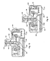
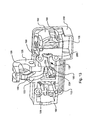
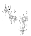
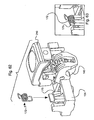
- the latch 100 includes a latch housing or frame 104, a pawl 140, a locking member 138, means for selectively moving the locking member between locked and unlocked positions and means for selectively disengaging the locking member from the pawl while the locking member is in the unlocked position.
- a handle 102 having an actuation arm 170 is provided for selectively disengaging the locking member 138 from the pawl 140 when the locking member 138 is in the unlocked position.
- the latch 100 can be used for securing a first member in a closed position relative to a second member.
- a keeper is usually provided in a stationary position relative to the second member and the keeper is engaged by the latch 100 to secure the first member in the closed position.
- the first member may, for example, be the door of the glove box of an automobile and the second member may, for example, be the structure defining the glove box opening.
- the latch 100 is usually mounted such that the front of the latch including the front of the handle faces the exterior of the glove box door, and the rear of the latch 100 faces the interior of the glove box.
- the frame 104 has a portion that closes off the open end of the pawl slot 156 when the pawl 140 is in the latched position. This can be accomplished by providing for a portion of the frame 104 to obstruct the opening of the slot 156 when the pawl 140 is in the latched position.
- the frame is preferably adapted to allow an unobstructed path to the opening of the pawl slot 156 when the pawl 140 is in the unlatched position.
- the latch 100 of the present invention is substantially identical in operation to that disclosed in U.S. Patent Number 5,927,772 .
- the rotary pawl latch 100 has an actuating member, such as, for example, the handle or paddle 102 that is pivotally mounted to the latch frame 104.
- the handle 102 is provided with flanges 106 and 108 which have holes 110 and 112, respectively.
- the frame 104 is provided with suitable means for the attachment of the handle 102 such as flanges 114 and 116 having projections 118 and 120, respectively.
- the projections 118 and 120 are received in holes 110 and 112, respectively, to pivotally attach the handle 102 to the frame 104.
- There are sloping surfaces ahead of the holes 110 and 112 so as to form ramps 122 and 124 which lead to the holes 110 and 112.
- the projections 118 and 120 are provided with beveled surfaces that align with the ramps 122 and 124 during assembly and by their interaction with the ramps 122 and 124 facilitate assembly.
- the flanges 114 and 116 and the flanges 106 and 108 have sufficient resilience such that the handle 102 can be snap-fitted to the frame 104. With the handle 102 positioned relative to the frame 104 such that the projections 118 and 120 register with the ramps 122 and 124, respectively, the handle 102 can be pressed toward the frame 104 until the projections 118 and 120 snap into the holes 110 and 112, respectively. Thus the handle 102 is pivotally attached to the frame 104.
- the handle 102 is also provided with shoulders 105 and 107 above the holes 110 and 112.
- the shoulders 105 and 107 are formed by surfaces that are sloping relative to the rear face 103 of the handle 102. Also, the shoulders 105 and 107 are sloping relative to the flanges 114 and 116 when the handle 102 is in the closed position. When the handle 102 reaches the open position the shoulders 105 and 107 contact the flanges 114 and 116 of the frame 104 and prevent further rotation of the handle 102 past the open position.
- the handle 102 also has a projection 109 that projects outward from the rear face 103 of the handle 102.
- the projection 109 contacts the front of the frame 104 and prevents further rotation of the handle 102 past the closed position.
- the shoulders 105, 107 and the projection 109 constitute means for limiting the rotation of the handle 102 and define the limits of the range of the rotational movement of the handle 102.
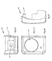
- the frame 104 is provided with a body portion 126 having a hook-like member 128 projecting therefrom.
- Hook-like refers to any member that has a crook, curve, or bend to thereby catch on another member.
- the hook-like member or flange 128 has a tip 130 that points toward a keeper (not shown) as the first member to which the latch 100 is attached is moved to the closed position.
- a first slot 132 is provided within the portion of the frame body 126 and extends through the hook-like member 128.
- the locking member 138 includes a base 136 and an elongated locking arm 180. The elongated locking arm 180 is resiliently attached to the base 136.
- the frame 104 has a cavity 134 for receiving and supporting the base 136 such that the base 136 and the elongated locking arm 180, i.e. the locking member 138, can move back and forth rectilinearly parallel to the axis of rotation of the pawl 140 within a predetermined range of motion.
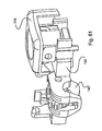
- the latch assembly 100 also includes a pawl 140 shown rotationally connected to the latch frame 104 with suitable attachment means such as the pawl pivot members 142 which are provided at opposite sides of the pawl 140 and extend outward from the opposite sides of the pawl 140. Only one of the pivot members 142 is shown in the accompanying illustrations, the other being a mirror image of the illustrated pivot member 142.
- the pivot members 142 can also be provided as a single pivot member extending through the pawl 140.
- the pawl 140 is installed in the frame 104 by snap-fit placement of the pawl pivot members 142 into the pawl pivot holes 144, 146 disposed in opposite sides of the slot 132. Flared-out guide ramps 148, 150 are provided on either side of the slot 132.
- the Flared-out guide ramps 148, 150 lead to the holes 144, 146, respectively.
- the guide ramps 148,150 guide the pawl pivot members 142 in the direction of the pawl pivot holes 144, 146 during the snap-fitting installation of the pawl 140 to the frame 104.
- the pawl 140 has a body portion 152 with the pair of pawl pivot members 142 extending in opposite directions from either side of the body portion 152.
- the pawl 140 has a locking engagement portion or projection 154 that is involved in selectively retaining the pawl 140 in the latched position.
- the pawl 140 also has a pawl claw 155 and a pawl arm 158 extending from the pawl body 152.
- the pawl claw 155 and the pawl arm 158 cooperatively define the pawl slot 156, which is located between the two.
- the pawl claw 155 moves behind the keeper that is in stationary relationship with the second member as the pawl 140 rotates to the latched position in order to hold the first member in the closed position.
- the impact of the keeper on the pawl arm 158 causes the rotation of the pawl 140 to the latched position as the first member is moved to the closed position.
- the pawl slot 156 provides the necessary clearance for the pawl 140 to complete its rotation to the latched position while allowing the keeper to be positioned between the pawl arm 158 and the pawl claw 155 without any part of the pawl coming into conflict with the keeper in a way that would prevent the pawl from completing its rotation to the latched position.
- the keeper member (not shown) may be attached to a stationary doorframe or a compartment opening at a position such that when a door to which the latch assembly 100 is attached is pivotally moved to the closed position, the keeper member will be positioned inside the crook or bend of the hook-like member 128. Furthermore, the keeper will impact and cause the rotation of the pawl 140 to the latched position wherein the keeper will become captured in the pawl slot 156.
- the latch assembly 100 also includes a pawl torsion spring 160 having two coiled portions 162.
- the pawl torsion spring 160 is installed on the pawl 140 with each the coiled portions 162 surrounding a respective one of the pawl pivot members 142.
- the torsion spring 160 includes a wire loop 164 that engages the notch 166 in the arm portion 158.
- the wire loop 164 is joined to a respective coiled portion 162 at each end. Lateral arms of the wire loop 164 extend from the respective coiled portions 162 to the notch 166 with the pawl arm 158 being positioned at least in part intermediate the lateral arms of the wire loop 164.
- the torsion spring 160 also has two tail portions 168.
- the pawl 140 is installed with the notch 166 positioned behind the pawl slot 156 as seen by an observer when the tip 130 faces toward the observer.
- each of the two tail portions 168 of the torsion spring 160 rests on a respective step 184 formed in either side of the slot 132.
- the wire loop 164 engaging the notch 166 exerts a force on the arm portion 158 of the pawl 140 that biases the pawl 140 toward the open or unlatched position.
- the handle 102 has an actuation arm 170 that extends toward the frame 104.
- a torsion spring 172 is provided between the handle 102 and the frame 104 that biases the handle 102 toward the closed position.
- the handle torsion spring 172 has a coiled portion 171 and two arms 173.
- the arms 173 have hooked ends.
- One of the arms 173 is received in a pocket 175 that that is provided as part of the frame 104.
- the arm 173 is positioned horizontally once it is received in the pocket 175.
- the pocket 175 extends horizontally from the front of the frame 104 to the rear of the frame 104 and is open at least at the front of the frame 104 so as to receive one of the arms 173 of the handle torsion spring 172.
- the other arm 173 of the handle torsion spring 172 presses against the rear face 103 of the handle 102 above the pivot axis of the handle 102, i.e. on the side of the pivot axis of the handle that is opposite the grasping portion 101 of the handle 102.
- the handle torsion spring 172 With the handle torsion spring 172 in this position, moving the handle 102 toward the open position forces the arms 173 of the handle torsion spring 172 closer to each other.
- the arms 173 of the handle torsion spring tend to move apart thus forcing the handle 102 back to the closed position.
- the actuation arm 170 of the handle 102 is provided to engage the actuator engaging end 174 of the elongated locking arm 180 of the locking member 138.
- the elongated locking arm 180 is provided to extend in front of the slot 176 in the frame body 104 when the locking member 138 is in the unlocked position.
- the elongated locking arm 180 is resiliently attached in cantilever fashion to the base 136 which is supported in the cavity 134.
- the actuating arm 170 extends through the slot 176 such that a portion of the actuating arm 170 is positioned over the actuator engaging end 174 of the locking member 138 when the locking member is in the unlocked position.
- the locking member 138 is also provided with a pawl engaging portion 178, positioned along the elongated locking arm 180, which engages the projection 154 of the pawl 140.
- the latch assembly 100 is actuated by lifting the grasping portion 101 of the handle 102 away from the frame 104 with the locking member in the unlocked position.
- the end 182 of the actuating arm 170 engages the actuator engaging end 174 of the locking member 138 and the actuator engaging end 174 is deflected away from the axis of rotation of the pawl 140.
- the elongated locking arm 180 of the locking member 138 is deflected sufficiently far from the axis of rotation of the pawl 140 such that the pawl engaging portion 178 of the locking member 138 is moved out of engagement with the projection 154 thereby freeing up the pawl 140 for rotation to the open position.
- the bias provided by the pawl torsion spring 160 moves the pawl 140 from its latched position, where the keeper would be captured by the pawl claw 155, and forces the pawl 140 to rotate to the open or unlatched position.
- the rotation of the pawl 140 to the unlatched position moves the pawl claw 155 such that the pawl claw no longer obstructs the keeper and the first member from being pulled away from one another.
- the keeper that was once captured in the pawl slot 156 may now be disengaged from the pawl 140.
- the first member that was being secured in the closed position by the latch 100 can then be opened.
- the keeper may be a U-shaped rod attached, for example, to the frame surrounding the opening of the compartment secured by the closure member to which the latch 100 is attached.
- any like suitable member such as a bar, claw, or other suitable attachment member may serve as a keeper.
- the locking member 138 With the elongated locking arm 180 of the locking member 138 deflected sufficiently far from the axis of rotation of the pawl 140 such that the pawl engaging portion 178 of the locking member 138 is moved out of engagement with the pawl 140, the locking member 138 is said to be in the deflected configuration.
- the elongated locking arm 180 of the locking member 138 is in the same position as when it is retaining the pawl 140 in the latched position, the locking member 138 is said to be in the undeflected configuration.
- Suitable mounting means are provided to retain the latch assembly 100 on a panel or closure member.
- installation of the latch assembly 100 to a panel may be accomplished with screws, rivets or pins which engage the holes 188 for fastening of the latch assembly to a closure member, such as for example, the door of the glove box of an automobile.
- the operation of the latch 100 during closing of the first member will now be described with the locking member in the unlocked position.
- the opening of the pawl slot 156 faces toward the keeper and is unobstructed by the hook-like member 128.
- the keeper passes between the tip 130 of the hook-like member 128 and the pawl claw 155 and impacts the pawl arm 158 causing the rotation of the pawl 140 to the latched position illustrated in the drawings.
- the cam surface 186 cams the elongated locking arm 180 of the locking member 138 out of the way of the projection 154 so that the pawl 140 can rotate to the latched position under the force imparted to the pawl 140 by the keeper.
- the locking member 138 will return to its undeflected configuration due to its own internal spring forces.
- the elongated locking arm 180 of the locking member 138 catches the flat side 190 of the projection 154 to keep the pawl 140 in the latched position illustrated in Figs. 1-12 , thus capturing the keeper in the pawl slot 156 and securing the first member to which the latch 100 is mounted in the closed position.
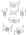
- the latch 100 is provided with means to lock the latch so as to prevent unauthorized access to the compartment secured by the latch 100. This is accomplished by providing a lock plug receptacle 192 as part of the frame 104.
- the receptacle 192 is adapted to receive a lock plug 194.
- the lock plug 194 is adapted for being selectively rotated between locked and unlocked positions by a user using a key.
- the lock plug is of a type having a series of wafers 196 that are normally biased to project from the lock plug 194 and engage a shoulder or step 198 in the receptacle 192 so as to prevent rotation of the lock plug 194 relative to the receptacle 192 between the locked position illustrated in Figs.
- the lock plug has a keyhole end 202, a locking member engaging end 204, and a longitudinal axis about which the lock plug 194 is rotated to move the lock plug between locked and unlocked positions.
- a cylindrical projection 206 projects from the locking member engaging end 204 of the lock plug 194 and extends into a slot 208 formed in the base 136 of the locking member 138.
- the projection 206 is offset, i.e. is eccentric, relative to the longitudinal axis of the lock plug such that it moves along a circular arc as the lock plug is rotated.
- the projection 206 extends in a direction parallel to the longitudinal axis of the lock plug 194.
- the locking member 138 As the projection 206 moves along its arc-shaped path resulting from the rotation of the lock plug 194 between locked and unlocked positions, the locking member 138 is moved rectilinearly between its locked and unlocked positions, respectively.
- the actuator engaging end 174 of the locking member 138 is moved out from under the actuating arm 170.
- the handle 102 can be moved from the closed to the open position without the actuating arm 170 of the handle engaging the actuator engaging end 174 of the locking member 138.
- actuating arm 170 cannot deflect the elongated locking arm 180 of the locking member 138 out of engagement with the pawl 140 and the pawl 140 will remain in the latched position even when the handle 102 is moved from the closed to the open position. Therefore, the latch 100 cannot be opened with the locking member in the locked position even if the handle 102 is moved to the open position.
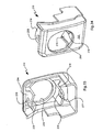
- the latch 100 is also provided with a lock plug receptacle cover 210 attached to the lock plug receptacle 192.
- the lock plug receptacle cover 210 is separate from the handle 102 and does not move relative to the frame 104 during operation of the latch 100.
- the lock plug receptacle cover 210 acts to increase resistance of the latch 100 to tampering by preventing or deterring the insertion of tools or instruments into the latch mechanism or the area of the lock plug when the handle is lifted to the open position.
- the lock plug receptacle cover 210 has a front face 212, a pair of partial sleeves 214 projecting from the backside of the front face 212, and a lock plug access opening 216.
- the partial sleeves 214 are positioned on opposite sides of the access opening 216. Each of the partial sleeves 214 is provided with a hole 218.
- the lock plug receptacle 192 is provided with projections 220 on the outside surface thereof. The projections 220 are received in holes 218 to attach the lock plug receptacle cover 210 to the lock plug receptacle 192. There are sloping surfaces ahead of the holes 218 so as to form ramps 222 that lead to the holes 218. Also the projections 220 are provided with beveled surfaces that align with the ramps 222 during assembly and by their interaction with the ramps 222 facilitate assembly.
- the partial sleeves 214 are resilient such that the lock plug receptacle cover 210 can be snap-fitted to the lock plug receptacle 192.
- the lock plug receptacle cover 210 With the lock plug receptacle cover 210 positioned relative to the lock plug receptacle 192 such that the projections 220 register with the ramps 222, the lock plug receptacle cover 210 can be pressed toward the frame 104 until the projections 220 snap into the holes 218.
- the lock plug receptacle cover 210 is attached to the lock plug receptacle 192 and consequently the frame 104.
- the frame 104 also has a projecting fin 224 positioned under the elongated locking arm 180 of the locking member 138.
- the locking member 138 has an open-ended slot 226 that registers with the fin 224 when the locking member 138 is in the unlocked position.
- the slot 226 provides clearance for the fin 224 such that the elongated locking arm 180 can be deflected out of engagement with the pawl to release the pawl from the latched position without interference from the fin 224.
- the fin 224 interferes with the movement of the elongated locking arm 180 such that the elongated locking arm 180 cannot be deflected out of engagement with the pawl to release the pawl from the latched position.
- This feature has the advantage that it prevents the elongated locking arm 180 from being deflected out of engagement with the pawl by insertion of some tool or instrument through the slot 176 to release the pawl from the latched position without the proper key and, therefore, enhances the tamper resistance of the latch 100.
- the locking member 138 includes a projection 228 that extends upward from the pawl engaging portion 178.
- the projection 228 is positioned intermediate the actuator engaging end 174 and the pawl 140 when the locking member 138 is in the unlocked position.
- Both the projection 228 and the portion of the pawl engaging portion 178 adjacent the projection 228 in the direction of the base 136 can engage the flat side 190 of the projection 154 to retain the pawl 140 in the latched position.
- the projection 228 can still clear the pawl body 152 in the direction of the lock plug receptacle 192, such that the locking member 138 can be moved to the locked position with the pawl 140 in the latched position.
- the pawl body 152 interferes with the projection 228.
- the projection 228 prevents the locking member 138 from being moved to the locked position.
- the elongated locking arm 180 of the locking member 138 cannot be deflected enough to allow movement of the pawl into or out of the latched position when the locking member 138 is in the locked position. Accordingly, if the locking member 138 could be moved to the locked position with the pawl 140 in the unlatched position, the latch 100 would not work properly and would not latch when the closure member to which the latch is attached is slammed shut.
- the slot 226 is positioned under the projection 228 such that the elongated locking arm 180 of the locking member 138 will not be weakened by the presence of the slot 226.
Claims (12)
- Ensemble de verrou (100) pour fixer de manière amovible un premier élément dans une position fermée par rapport à un second élément, le second élément ayant une gâche dans une relation positionnelle fixe avec ce dernier, l'ensemble de verrou (100) comprenant :un bâti (104) adapté pour se fixer sur le premier élément, ledit bâti (104) étant prévu avec une poche (175) ;un cliquet (140) supporté en rotation par ledit bâti (104), ledit cliquet (140) étant mobile en rotation entre des positions verrouillée et déverrouillée ;un élément de verrouillage (138) supporté par ledit bâti (104), ledit élément de verrouillage (138) étant mobile de manière rectiligne entre des positions de verrouillage et de déverrouillage, ledit élément de verrouillage (138) étant également capable de prendre une configuration déviée au moins lorsque ledit élément de verrouillage (138) est dans ladite position de déverrouillage, ledit élément de verrouillage (138) étant également capable de prendre une configuration non déviée, ledit élément de verrouillage (138) mettant en prise et retenant ledit cliquet (140) dans ladite position verrouillée lorsque ledit cliquet (140) est dans ladite position verrouillée, et ledit élément de verrouillage (138) est dans ladite configuration non déviée, ledit élément de verrouillage (138) libérant ledit cliquet (140) de ladite position verrouillée lorsque ledit élément de verrouillage (138) prend ladite configuration déviée alors que ledit élément de verrouillage (138) est dans ladite position de déverrouillage ;une poignée (102) fixée de manière pivotante sur ledit bâti (104) et étant mobile entre une position fermée et une position ouverte, ladite poignée (102) amenant ledit élément de verrouillage (138) à prendre ladite configuration déviée lorsque ledit élément de verrouillage (138) est dans ladite position de déverrouillage et ladite poignée (102) est déplacée vers la position ouverte, ledit élément de verrouillage (138) étant positionné dans ladite position de déverrouillage de sorte que ledit élément de verrouillage (138) ne peut pas être mis en prise par ladite poignée (102), ladite poignée (102) ayant une partie de préhension (101) et une face arrière (103) et se déplaçant de manière pivotante autour d'un axe de pivot ;un barillet de serrure (194) supporté par ledit bâti (104), ledit barillet de serrure (194) étant adapté pour être sélectivement entrainé en rotation entre des positions de verrouillage et de déverrouillage par un utilisateur à l'aide d'une clé, ledit barillet de serrure (194) mettant en prise ledit élément de verrouillage (138) de sorte que la rotation dudit barillet de serrure (194) entre les positions de verrouillage et de déverrouillage déplace ledit élément de verrouillage (138) entre les positions de verrouillage et de déverrouillage, respectivement ; dans lequel l'ensemble de verrou (100) est caractérisé par :un ressort de torsion de poignée (172) supporté par ledit bâti (104), ledit ressort de torsion de poignée (172) ayant une partie enroulée (171) et deux bras (173), l'un des bras (173) dudit ressort de torsion de poignée (172) étant reçu dans ladite poche (175) et l'autre desdits bras (173) dudit ressort de torsion de poignée (172) appuyant contre ladite face arrière (103) de ladite poignée (102) du côté dudit axe de pivot de ladite poignée (102) qui est opposé à ladite partie de préhension (101) de ladite poignée (102), de sorte que ledit ressort de torsion de poignée (172) sollicite ladite poignée (102) vers ladite position fermée.
- Ensemble de verrou (100) selon la revendication 1, dans lequel ledit bâti (104) a un réceptacle de barillet de serrure (192), l'ensemble de verrou (100) comprenant en outre :un barillet de serrure (194) supporté par ledit bâti (104), ledit barillet de serrure (194) étant adapté pour être sélectivement entraîné en rotation entre des positions de verrouillage et de déverrouillage par un utilisateur à l'aide d'une clé, ledit barillet de serrure (194) mettant en prise ledit élément de verrouillage (138) de sorte que la rotation dudit barillet de serrure (194) entre les positions de verrouillage et de déverrouillage déplace ledit élément de verrouillage (138) entre les positions de verrouillage et de déverrouillage, respectivement ; etun couvercle de réceptacle de barillet de serrure (210) fixé sur ledit réceptacle de barillet de serrure (192), ledit couvercle de réceptacle de barillet de serrure (210) étant séparé de ladite poignée (102) et servant à augmenter la résistance dudit ensemble de verrou (100) à l'effraction.
- Ensemble de verrou (100) selon la revendication 2, dans lequel ledit couvercle de réceptacle de barillet de serrure (210) a une paire de manchons partiels (214) faisant saillie à partir de l'un de ses côtés, ladite paire de manchons partiels (214) étant adaptée pour se fixer par encliquetage sur ledit bâti (104).
- Ensemble de verrou (100) selon la revendication 3, dans lequel ledit bâti (104) comprend un réceptacle de barillet de serrure (192) et dans lequel ladite paire de manchons partiels (214) est positionnée autour dudit réceptacle de barillet de serrure (192).
- Ensemble de verrou (100) selon la revendication 4, dans lequel ledit réceptacle de barillet de serrure (192) est prévu avec une paire de saillies (109, 118, 154, 206, 220) et chacun des manchons partiels de ladite paire de manchons partiels (214) est prévu avec un trou (218), et dans lequel chacune des saillies de ladite paire de saillies (220) est reçue dans ledit trou (218) d'un manchon partiel respectif de ladite paire de manchons partiels (214) afin de fixer ledit couvercle de réceptacle de barillet de serrure (210) sur ledit bâti (104).
- Ensemble de verrou (100) selon la revendication 5, dans lequel chacun des manchons partiels de ladite paire de manchons partiels (214) est prévu avec une rampe (222) qui mène audit trou (218) de chacun des manchons partiels de ladite paire de manchons partiels (214) qui facilite la fixation dudit couvercle de réceptacle de barillet de serrure (210) sur ledit bâti (104) par le biais d'une fixation par encliquetage.
- Ensemble de verrou (100) selon la revendication 1,
dans lequel ledit bâti (104) comprend une ailette (224), dans lequel ledit élément de verrouillage (138) a une fente à extrémité ouverte (226) qui s'aligne avec ladite ailette (224) lorsque ledit élément de verrouillage (138) est dans ladite position de déverrouillage de sorte que ladite fente (226) fournit un jeu pour ladite ailette (224) pour permettre ainsi audit élément de verrouillage (138) d'être dévié hors de la mise en prise d'avec ledit cliquet (140) afin de libérer ledit cliquet (140) de ladite position verrouillée sans interférence de la part de ladite ailette (224), et dans lequel lorsque ledit élément de verrouillage (138) est dans ladite position de verrouillage, ladite ailette (224) interfère avec ledit mouvement dudit élément de verrouillage (138), de sorte que ledit élément de verrouillage (138) ne peut pas être dévié hors de mise de prise d'avec ledit cliquet (140) pour libérer ledit cliquet (140) de ladite position verrouillée. - Ensemble de verrou (100) selon la revendication 7, dans lequel ledit bâti (104) a un réceptacle de barillet de serrure (192), l'ensemble de verrou (100) comprenant en outre :un couvercle de réceptacle de barillet de serrure (210) fixé sur ledit réceptacle de barillet de serrure (192), ledit couvercle de réceptacle de barillet de serrure (210) étant séparé de ladite poignée (102) et servant à augmenter la résistance dudit ensemble de verrou (100) à l'effraction.
- Ensemble de verrou (100) selon la revendication 8, dans lequel ledit couvercle de réceptacle de barillet de serrure (210) a une paire de manchons partiels (214) faisant saillie à partir de l'un de ses côtés, ladite paire de manchons partiels (214) étant adaptée pour se fixer par encliquetage sur ledit bâti (104).
- Ensemble de verrou (100) selon la revendication 9, dans lequel ledit bâti (104) comprend un réceptacle de barillet de serrure (192) et dans lequel ladite paire de manchons partiels (214) est positionnée autour dudit réceptacle de barillet de serrure (192).
- Ensemble de verrou (100) selon la revendication 10, dans lequel ledit réceptacle de barillet de serrure (192) est prévu avec une paire de saillies (220) et chacun des manchons partiels de ladite paire de manchons partiels (214) est prévu avec un trou (218), et dans lequel chacune des saillies de ladite paire de saillies (220) est reçue dans ledit trou (218) d'un manchon partiel respectif de ladite paire manchons partiels (214) afin de fixer ledit couvercle de réceptacle de barillet de serrure (210) sur ledit bâti (104).
- Ensemble de verrou (100) selon la revendication 11, dans lequel chacun des manchons partiels de ladite paire de manchons partiels (214) est prévu avec une rampe (222) qui mène audit trou (218) de chacun des manchons partiels de ladite paire de manchons partiels (214) qui facilite la fixation dudit couvercle de réceptacle de barillet de serrure (210) sur ledit bâti (104) par le biais d'une fixation par encliquetage.
Applications Claiming Priority (2)
| Application Number | Priority Date | Filing Date | Title |
|---|---|---|---|
| US61140904P | 2004-09-19 | 2004-09-19 | |
| PCT/US2005/033211 WO2006034057A1 (fr) | 2004-09-19 | 2005-09-16 | Verrou a cliquet rotatif |
Publications (3)
| Publication Number | Publication Date |
|---|---|
| EP1797259A1 EP1797259A1 (fr) | 2007-06-20 |
| EP1797259A4 EP1797259A4 (fr) | 2014-06-25 |
| EP1797259B1 true EP1797259B1 (fr) | 2015-07-08 |
Family
ID=36090342
Family Applications (1)
| Application Number | Title | Priority Date | Filing Date |
|---|---|---|---|
| EP05797572.4A Active EP1797259B1 (fr) | 2004-09-19 | 2005-09-16 | Verrou a cliquet rotatif |
Country Status (4)
| Country | Link |
|---|---|
| US (1) | US7748245B2 (fr) |
| EP (1) | EP1797259B1 (fr) |
| CN (1) | CN101057050B (fr) |
| WO (1) | WO2006034057A1 (fr) |
Families Citing this family (10)
| Publication number | Priority date | Publication date | Assignee | Title |
|---|---|---|---|---|
| WO2006034057A1 (fr) | 2004-09-19 | 2006-03-30 | Southco, Inc. | Verrou a cliquet rotatif |
| KR20070101376A (ko) | 2005-02-12 | 2007-10-16 | 사우스코 인코포레이티드 | 자기 래치 기구 |
| US9004550B2 (en) | 2005-05-08 | 2015-04-14 | Southco, Inc. | Magnetic latch mechanism |
| JP4695522B2 (ja) * | 2006-02-14 | 2011-06-08 | 株式会社パイオラックス | リッドのロック装置 |
| DE102007012616A1 (de) * | 2006-03-16 | 2007-10-31 | Southco, Inc. | Drehklinkenverriegelung für ein Handschuhfach |
| WO2008022293A2 (fr) | 2006-08-16 | 2008-02-21 | Southco, Inc. | Verrou à cliquet rotatif |
| DE112008000129T5 (de) | 2007-01-06 | 2010-01-14 | Southco, Inc. | Magnetschlossmechanismus |
| EP2245245B1 (fr) * | 2008-01-31 | 2017-08-16 | Hartwell Corporation | Loquet de canal actionné par un outil |
| US20100108622A1 (en) * | 2008-11-06 | 2010-05-06 | Gabriel George S | Locking assembly |
| US9169675B2 (en) * | 2012-09-25 | 2015-10-27 | Ford Global Technologies, Llc | Closure device for a compartment |
Family Cites Families (31)
| Publication number | Priority date | Publication date | Assignee | Title |
|---|---|---|---|---|
| JPS6019879Y2 (ja) * | 1977-09-27 | 1985-06-14 | 株式会社糸井製作所 | 引き出し付収納庫 |
| US4192536A (en) * | 1978-07-13 | 1980-03-11 | Bel Air Aluminum Manufacturing, Inc. | Push-pull door latch |
| AU5579380A (en) * | 1979-03-01 | 1980-09-04 | Itw Ltd. | Adjustable handle mounting |
| US4510779A (en) * | 1982-07-16 | 1985-04-16 | Adams Rite Products, Inc. | Aircraft door lock actuating mechanism |
| US5046340A (en) * | 1984-04-18 | 1991-09-10 | The Eastern Company | Latch and lock assemblies with spring-biased pivot bolts |
| US4679836A (en) | 1986-03-21 | 1987-07-14 | General Motors Corporation | Closure latch |
| US4813722A (en) * | 1987-10-20 | 1989-03-21 | Chrysler Motors Corporation | Locking device for vehicle fold-down seat backrest |
| DE4321586C2 (de) * | 1992-06-29 | 1995-06-08 | Ohi Seisakusho Co Ltd | Motorbetriebene Schließvorrichtung |
| US5263750A (en) * | 1992-10-01 | 1993-11-23 | General Motors Corporation | Snap-together door handle and housing assembly for a vehicle |
| US5299844A (en) * | 1992-10-30 | 1994-04-05 | Tri/Mark Corporation | Sealed latch assembly |
| US5413391A (en) * | 1993-07-12 | 1995-05-09 | Hartwell Corporation | Self-closing latch |
| US5794994A (en) * | 1995-08-09 | 1998-08-18 | Ohi Seisakusho Co., Ltd. | Inside door handle unit for automotive vehicle |
| US5941104A (en) * | 1997-09-03 | 1999-08-24 | Randall C. Hansen | Paddle lock |
| US5927772A (en) * | 1997-09-12 | 1999-07-27 | Southco, Inc. | Ratcheting pawl latch |
| US6048006A (en) * | 1997-09-12 | 2000-04-11 | Southco, Inc. | Ratcheting pawl latch |
| US5984383A (en) * | 1997-10-17 | 1999-11-16 | Cleveland Hardware And Forging Company | Lockable slammable cam latch with handle key hole cover |
| US6139073A (en) * | 1998-08-31 | 2000-10-31 | Westinghouse Air Brake Company | Lock assembly |
| WO2001038671A2 (fr) | 1999-11-29 | 2001-05-31 | Southco, Inc. | Verrou a encliquetage |
| WO2001046543A2 (fr) * | 1999-12-20 | 2001-06-28 | Southco, Inc. | Loquet a cliquet |
| WO2001066890A2 (fr) * | 2000-03-07 | 2001-09-13 | Southco, Inc. | Verrou sensible a la gravite |
| US6460902B1 (en) * | 2000-10-27 | 2002-10-08 | Pompanette, Inc. | Slam latch and hatch assembly including a slam latch |
| WO2002036907A2 (fr) * | 2000-11-01 | 2002-05-10 | Southco, Inc. | Dispositif de verrouillage |
| US6471260B1 (en) * | 2001-08-06 | 2002-10-29 | The Eastern Company | Rotary latches with enhanced service longevity |
| EP1497156B1 (fr) * | 2002-04-07 | 2011-08-24 | Southco, Inc. | Dispositif de verrouillage de boite a gants |
| EP1540118A2 (fr) * | 2002-07-01 | 2005-06-15 | Southco, Inc. | Systeme de verrouillage a deux points |
| US6942259B2 (en) * | 2002-12-11 | 2005-09-13 | Tri/Mark Corporation | Latch assembly |
| EP2669454B1 (fr) * | 2003-07-10 | 2019-11-20 | Southco, Inc. | Verrou à cliquet rotatif |
| EP1663738B1 (fr) * | 2003-08-22 | 2017-03-01 | Southco, Inc. | Verrou a cliquet rotatif muni d'un palette de verrouillage |
| USD506120S1 (en) * | 2004-02-22 | 2005-06-14 | Southco, Inc. | Multi-directional rotary-pawl latch |
| WO2006034057A1 (fr) | 2004-09-19 | 2006-03-30 | Southco, Inc. | Verrou a cliquet rotatif |
| DE102007012616A1 (de) * | 2006-03-16 | 2007-10-31 | Southco, Inc. | Drehklinkenverriegelung für ein Handschuhfach |
-
2005
- 2005-09-16 WO PCT/US2005/033211 patent/WO2006034057A1/fr active Application Filing
- 2005-09-16 EP EP05797572.4A patent/EP1797259B1/fr active Active
- 2005-09-16 US US11/575,468 patent/US7748245B2/en active Active
- 2005-09-16 CN CN2005800388980A patent/CN101057050B/zh active Active
Also Published As
| Publication number | Publication date |
|---|---|
| CN101057050A (zh) | 2007-10-17 |
| EP1797259A1 (fr) | 2007-06-20 |
| US7748245B2 (en) | 2010-07-06 |
| CN101057050B (zh) | 2011-12-14 |
| US20090179438A1 (en) | 2009-07-16 |
| WO2006034057A1 (fr) | 2006-03-30 |
| EP1797259A4 (fr) | 2014-06-25 |
Similar Documents
| Publication | Publication Date | Title |
|---|---|---|
| EP1797259B1 (fr) | Verrou a cliquet rotatif | |
| US7065992B2 (en) | Rotary pawl latch with lock down paddle | |
| EP1330584B1 (fr) | Dispositif de verrouillage | |
| US7726707B2 (en) | Rotary pawl latch | |
| US5630630A (en) | Glove compartment latch mechanism | |
| US5820174A (en) | Lockable slammable paddle latch | |
| US5044182A (en) | Automatic deadbolt | |
| US20050183478A1 (en) | Latch | |
| US7269984B2 (en) | Ratcheting pawl latch | |
| US7096538B2 (en) | Vehicle door hinge system | |
| GB2325270A (en) | Automotive door latch | |
| EP1179108B1 (fr) | Verrou | |
| US7654589B2 (en) | Rotary action draw latch | |
| US5474340A (en) | Theft-resistant motor-vehicle door latch | |
| US20050183477A1 (en) | Latch | |
| JPH0510113Y2 (fr) | ||
| WO2001046543A2 (fr) | Loquet a cliquet | |
| EP0968347B1 (fr) | Serrure | |
| JPH04130683U (ja) | ガードアーム装置付錠前 | |
| KR19980046724U (ko) | 자동차의 후면도어 잠금장치 | |
| JPS631434B2 (fr) | ||
| KR101024986B1 (ko) | 자동차용 트렁크리드의 래치장치 | |
| JPH0561370U (ja) | 開閉ドアのロック装置 | |
| WO2001021912A1 (fr) | Loquet a cliquet | |
| GB2177449A (en) | Improved fastening apparatus |
Legal Events
| Date | Code | Title | Description |
|---|---|---|---|
| PUAI | Public reference made under article 153(3) epc to a published international application that has entered the european phase |
Free format text: ORIGINAL CODE: 0009012 |
|
| 17P | Request for examination filed |
Effective date: 20070327 |
|
| AK | Designated contracting states |
Kind code of ref document: A1 Designated state(s): DE |
|
| DAX | Request for extension of the european patent (deleted) | ||
| RBV | Designated contracting states (corrected) |
Designated state(s): DE |
|
| A4 | Supplementary search report drawn up and despatched |
Effective date: 20140526 |
|
| RIC1 | Information provided on ipc code assigned before grant |
Ipc: E05C 3/16 20060101ALI20140520BHEP Ipc: E05B 13/00 20060101ALI20140520BHEP Ipc: E05B 85/18 20140101ALI20140520BHEP Ipc: E05B 83/30 20140101AFI20140520BHEP |
|
| REG | Reference to a national code |
Ref country code: DE Ref legal event code: R079 Ref document number: 602005046925 Country of ref document: DE Free format text: PREVIOUS MAIN CLASS: E05B0003000000 Ipc: E05B0083300000 |
|
| GRAP | Despatch of communication of intention to grant a patent |
Free format text: ORIGINAL CODE: EPIDOSNIGR1 |
|
| RIC1 | Information provided on ipc code assigned before grant |
Ipc: E05B 13/00 20060101ALI20150106BHEP Ipc: E05B 83/30 20140101AFI20150106BHEP Ipc: E05B 85/18 20140101ALI20150106BHEP Ipc: E05C 3/16 20060101ALI20150106BHEP |
|
| INTG | Intention to grant announced |
Effective date: 20150204 |
|
| GRAS | Grant fee paid |
Free format text: ORIGINAL CODE: EPIDOSNIGR3 |
|
| GRAA | (expected) grant |
Free format text: ORIGINAL CODE: 0009210 |
|
| AK | Designated contracting states |
Kind code of ref document: B1 Designated state(s): DE |
|
| REG | Reference to a national code |
Ref country code: DE Ref legal event code: R096 Ref document number: 602005046925 Country of ref document: DE |
|
| REG | Reference to a national code |
Ref country code: DE Ref legal event code: R097 Ref document number: 602005046925 Country of ref document: DE |
|
| PLBE | No opposition filed within time limit |
Free format text: ORIGINAL CODE: 0009261 |
|
| STAA | Information on the status of an ep patent application or granted ep patent |
Free format text: STATUS: NO OPPOSITION FILED WITHIN TIME LIMIT |
|
| 26N | No opposition filed |
Effective date: 20160411 |
|
| PGFP | Annual fee paid to national office [announced via postgrant information from national office to epo] |
Ref country code: DE Payment date: 20230726 Year of fee payment: 19 |