EP1795686B1 - Rahmen für eine verdeckt liegende Schiebetür mit einer Nivelliervorrichtung - Google Patents
Rahmen für eine verdeckt liegende Schiebetür mit einer Nivelliervorrichtung Download PDFInfo
- Publication number
- EP1795686B1 EP1795686B1 EP06024174A EP06024174A EP1795686B1 EP 1795686 B1 EP1795686 B1 EP 1795686B1 EP 06024174 A EP06024174 A EP 06024174A EP 06024174 A EP06024174 A EP 06024174A EP 1795686 B1 EP1795686 B1 EP 1795686B1
- Authority
- EP
- European Patent Office
- Prior art keywords
- counterframe
- sliding door
- shaped
- concealed sliding
- bracket
- Prior art date
- Legal status (The legal status is an assumption and is not a legal conclusion. Google has not performed a legal analysis and makes no representation as to the accuracy of the status listed.)
- Active
Links
Images

Classifications
-
- E—FIXED CONSTRUCTIONS
- E06—DOORS, WINDOWS, SHUTTERS, OR ROLLER BLINDS IN GENERAL; LADDERS
- E06B—FIXED OR MOVABLE CLOSURES FOR OPENINGS IN BUILDINGS, VEHICLES, FENCES OR LIKE ENCLOSURES IN GENERAL, e.g. DOORS, WINDOWS, BLINDS, GATES
- E06B3/00—Window sashes, door leaves, or like elements for closing wall or like openings; Layout of fixed or moving closures, e.g. windows in wall or like openings; Features of rigidly-mounted outer frames relating to the mounting of wing frames
- E06B3/32—Arrangements of wings characterised by the manner of movement; Arrangements of movable wings in openings; Features of wings or frames relating solely to the manner of movement of the wing
- E06B3/34—Arrangements of wings characterised by the manner of movement; Arrangements of movable wings in openings; Features of wings or frames relating solely to the manner of movement of the wing with only one kind of movement
- E06B3/42—Sliding wings; Details of frames with respect to guiding
- E06B3/46—Horizontally-sliding wings
- E06B3/4654—Horizontally-sliding wings disappearing in pockets in the wall; Pockets therefor
-
- E—FIXED CONSTRUCTIONS
- E05—LOCKS; KEYS; WINDOW OR DOOR FITTINGS; SAFES
- E05D—HINGES OR SUSPENSION DEVICES FOR DOORS, WINDOWS OR WINGS
- E05D15/00—Suspension arrangements for wings
- E05D15/06—Suspension arrangements for wings for wings sliding horizontally more or less in their own plane
- E05D15/0621—Details, e.g. suspension or supporting guides
-
- E—FIXED CONSTRUCTIONS
- E05—LOCKS; KEYS; WINDOW OR DOOR FITTINGS; SAFES
- E05Y—INDEXING SCHEME ASSOCIATED WITH SUBCLASSES E05D AND E05F, RELATING TO CONSTRUCTION ELEMENTS, ELECTRIC CONTROL, POWER SUPPLY, POWER SIGNAL OR TRANSMISSION, USER INTERFACES, MOUNTING OR COUPLING, DETAILS, ACCESSORIES, AUXILIARY OPERATIONS NOT OTHERWISE PROVIDED FOR, APPLICATION THEREOF
- E05Y2900/00—Application of doors, windows, wings or fittings thereof
- E05Y2900/10—Application of doors, windows, wings or fittings thereof for buildings or parts thereof
- E05Y2900/13—Type of wing
- E05Y2900/132—Doors
- E05Y2900/14—Doors disappearing in pockets of a wall, e.g. so-called pocket doors
Definitions
- This invention relates to a counterframe for a concealed sliding door with a levelling device.
- the proposal finds particular although not exclusive application in the sector of the industry for the manufacturing of components for closures, particularly for closures that are made up of doors of the concealed sliding type.
- the sliding doors of the concealed type are structured in such a way as to comprise a series of fixed elements that are intended to be integrated into the wall structure and also to constitute the coating, a wall and a series of movable parts, which are intended to be used during the door installation stage in order to be removed subsequently.
- a counterframe in order to be integrated into the wall structure, for example, there is a counterframe.
- the fixed elements mentioned are associated with the wall structure and comprise at least one casing to constitute the structure within which the door panel will be contained once said panel is made to slide until reaching the opening position, in addition to a door post intended to be fixed to the wall in correspondence with the vertical profile of the door frame, opposite to the positioning profile of the casing mentioned, in such a way as to allow, once closed, the door itself to rest under it. Furthermore, a longitudinal guide is engaged above the casing, by being screwed to said load-bearing structure.
- a sliding track is conventionally provided in order to allow the effective opening and closing movement of the sliding door.
- the door is suspended to the mentioned sliding track by conventional means, usually of the trolley type.
- the sliding track which is placed in correspondence with the upper part of the door frame structure, is provided with sliding means.
- the aim of this invention is also to overcome the aforementioned limitations or drawbacks.
- a counterframe for concealed sliding doors with a levelling device including at least one first support device and at least one second support device, each including an L-shaped bracket provided with horizontal openings, in the first support device said bracket is joined to an adjustable square provided with guide openings that engages a shaped support body, while the second support device is joined to an adjustable support element which is provided with guide openings as well as an end provided with a clamping fork, wherein at least one first support device partially engages the horizontal elements of the base of the casing of the counterframe, while the lower end of the door post of the counterframe engages the second support device.
- a first aim consists in producing a counterframe for a concealed sliding door with a levelling device, by means of which it is possible to obtain the optimal levelling of said counterframe through of the use of devices which may be quickly and easily prepared and that are of the adjustable type.
- a second advantageous aim consists in producing a counterframe for a concealed sliding door with a levelling device through which it is possible to obtain greater stability and the optimal levelling of the counterframe already in the installation stage, without needing to resort to successive adjustment interventions.
- a third advantageous aim consists in producing a counterframe for a concealed sliding door with a levelling device, through the use of which it is possible to obtain a considerable reduction in installation times with the consequent limiting of related costs.
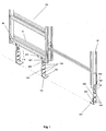
- this invention is made up of a counterframe for a concealed sliding door with a levelling device, particularly adapted to counterframe structures for concealed sliding doors of the type to be integrated into walls, such as for example partition walls in plasterboard or in stone with plaster covering, wherein said counterframe structure is of the conventional type and includes a series of fixed elements intended to be integrated into the wall structure as well as a series of movable parts, intended to be used during the installation stage.
- the fixed elements mentioned provided are associated with the wall structure and include at least one casing 100 intended to constitute the structure within which the door will be contained once it has been made to slide until reaching the opening position, in addition to a door post intended to be fixed to the wall in correspondence with the vertical profile of the door frame, opposite positioning profile of the casing mentioned.
- the base of the casing 110 coinciding with the lower side of the casing 100 provided, in the example, provides connecting transversal elements 70, 80.
- the counterframe is provided to comprise at least one first support device 1 engaged to the base of the casing 110, and in more detail, in the example, is engaged to the connecting transversal elements 70, 80 of the counterframe, and a second support device 2 engaged to the door post 90 of the counterframe, wherein both the first support device 1 as well as the second support device 2 are structured in such a way as to be adjustable.
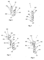
- both the first support device 1 as well as the second support device 2 include a bracket 10, 20, that is L-shaped and provided, in correspondence with the centre of the horizontal portion 101, 201 , with a through hole 1 02, 202 for the engagement of the bracket 10, 20, usually by means of a nail or a fastening screw, to the concrete slabs of the floor.
- the bracket 10, 20 is provided with horizontal openings 104, 204, that are equidistant and parallel to each other.
- at least one horizontal opening 104 constitutes a seat for engagement, usually through the bolting of an adjustable square 30, that is superimposed and slideable in relation to the bracket 10,20, said adjustable square 30 consisting of a vertical wall 301 that is orthogonal to a horizontal wall 303, wherein the adjustable square 30 in correspondence to the vertical wall 301 is provided with guide openings 302, which are arranged vertically, as well as equidistant and parallel in relation to each other.
- the provision of the horizontal openings 104 of the bracket 10 and of guide openings 302 with which the adjustable square 30 is provided allows the execution of the adjustment of the adjustable square 30 in relation to the bracket 10 both in the vertical as well as horizontal direction thus allowing the adjustment and fixing in position judged to most convenient for levelling.
- the horizontal wall 303 of the square 30, is provided to be hooked to a shaped support body 40,50.
- the horizontal wall 303 of the adjustable square 30 is to be held by a holding track 401, 501 that is provided on the lower part of the base wall 402, 502 of the shaped support body 40, 50.
- the holding track 401, 501 is produced by means of the suitable cutting and folding of the portion cut in such a way as to produce the holding track 401, 501 so that is made up of two guide elements 411, 412, 511, 512, symmetric and specular to each other, which are shaped in such a way as to form two L-shaped projecting flanges.
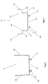
- the shaped support body 40, 50 is provided with two side walls 403, 404, 503, 504, orthogonal to the base wall 402, 502.
- the side walls 403, 404, of the shaped support body 40 are to be flat, each being symmetrical and parallel in relation to the other, wherein each of the two side walls 403, 404, is further to form an angle with the base wall 402 equal to 92°.
- the internal measurement of the base wall 402 is equal to 58 mm, while the measurement of each of the two side walls 403, 404 is internally equal to 43 mm and externally equal to 44.16 mm.
- the side walls 503, 504, of the shaped support body 50 to be shaped like a step so that in correspondence with the two opposite lateral ends of the base wall 502, for each of the two shaped walls 503, 504 a first vertical portion 531, 541 is produced, orthogonal to the base wall 502, and orthogonally to the first vertical portion 531, 541 is a horizontal portion 532, 542 which continues with a second vertical portion 533, 543 orthogonal in relation to the horizontal portion 532, 542.
- each first vertical portion 531, 541 of each of the two shaped walls 503, 504 is to have a height equal to 16.8 mm
- the measurement of the width of the horizontal portion 532, 542 is 9.8 mm
- the measurement of the height of the second vertical portion 533, 543 is to be 12 mm, so that that the intervening distance between the second vertical portion 533, 543 of the two shaped walls 503, 504 is 75 mm.
- the second support device 2 provides, bolted to the bracket 20, an adjustable support element 60, that is superimposed and slideable in relation to the bracket 20, consisting of a metallic plate, provided with guide openings 601 that are vertical, parallel and reciprocally equidistant for the height adjustment of said plate.
- the adjustable support element 60 is further equipped with a clamping fork 602 obtained by means of the external folding of a cut portion.
Landscapes
- Engineering & Computer Science (AREA)
- Civil Engineering (AREA)
- Structural Engineering (AREA)
- Wing Frames And Configurations (AREA)
- Elevator Door Apparatuses (AREA)
- Specific Sealing Or Ventilating Devices For Doors And Windows (AREA)
- Power-Operated Mechanisms For Wings (AREA)
Claims (10)
- Gegenrahmen für einfahrbare Schiebetür mit mindestens einem Kasten und einem Türanschlagpfosten, gekennzeichnet dadurch, dass der Kastenboden 110 mindestens in eine erste Stützvorrichtung 1 eingreift, die einen Bügel 10, 20 umfasst, der mit mindestens einem horizontalen Schlitz 104 versehen ist, der in den Bügel 10, 20 eingreift, sowie einen verstellbaren Winkelbeschlag 30 umfasst, der mit mindestens einem Führungsschlitz 302 versehen ist, wobei der verstellbare Winkelbeschlag 30 in einen Formstützkörper 40, 50 eingreift, während das untere Ende des Türanschlagpfostens 90 des Gegenrahmens in mindestens eine zweite Stützvorrichtung 2 eingreift, die einen Bügel 10, 20 umfasst, der mit mindestens einem horizontalen Schlitz 204 versehen ist, in welchen ein verstellbares Stützelement 60 eingreift und verstellbar ist, das mit mindestens einem senkrechten Schlitz 601 und einer Einrastgabel 602 versehen ist.
- Gegenrahmen für eine einfahrbare Schiebetür nach Anspruch 1, gekennzeichnet dadurch, dass der Bügel 10, 20 L-förmig ist und auf der Mitte des waagrechten Teils 101, 201 mit einer Durchgangsbohrung 102, 202 versehen ist, wobei die waagerechten Schlitze 104, 204, mit welchen der senkrechte Teil 103, 203 des Bügels 10, 20 versehen ist, abstandsgleich und parallel zueinander sind.
- Gegenrahmen für eine einfahrbare Schiebetür nach Anspruch 1 und 2 gekennzeichnet dadurch, dass der verstellbare Winkelbeschlag 30 und das verstellbare Trägerelement 60 übereinander liegen und zum Bügel 10, 20 hin gleitbar sind.
- Gegenrahmen für die einfahrbare Schiebetür nach den vorherigen Ansprüchen, gekennzeichnet dadurch, dass die Führungsschlitze 302, mit welchen der verstellbare Winkelbeschlag 30 versehen ist, entlang der senkrechten Wand 301 gezogen und senkrecht angeordnet sind sowie jeder abstandsgleich und parallel zum anderen ist.
- Gegenrahmen für die einfahrbare Schiebetür nach den vorherigen Ansprüchen, gekennzeichnet dadurch, dass der Formstützkörper 40, 50 zum Unterteil der Basiswand 402, 502 hin mit einer Halteschiene 401, 501 versehen ist und des weiteren zwei rechtwinklige Seitenwände 403, 404, 503, 504 zur Basiswand 402, 502 aufweist.
- Gegenrahmen für eine einfahrbare Schiebetür nach den vorherigen Ansprüchen, gekennzeichnet dadurch, dass die Halteschiene 401, 501 aus zwei Führungselementen 411, 412, 511, 512 besteht, die spiegelsymmetrisch zueinander liegen und so geformt sind, dass sie zwei L-förmige vorstehende Flansche bilden.
- Gegenrahmen für eine einfahrbare Schiebetür nach den vorherigen Ansprüchen, gekennzeichnet dadurch, dass die senkrechten Schlitze 601 des verstellbaren Trägerelements 60 abstandsgleich und parallel zueinander sind.
- Gegenrahmen für die einfahrbare Schiebetür nach den vorherigen Ansprüchen, gekennzeichnet dadurch, dass die beiden Seitenwände 403, 404 des Formstützkörpers 40 flach sind und jede symmetrisch und parallel zur anderen ist.
- Gegenrahmen für die einfahrbare Schiebetür nach den vorherigen Ansprüchen, gekennzeichnet dadurch, dass jede der zwei Seitenwände 403, 404, des Formstützkörpers 40 einen gleichmäßigen Winkel von 92° mit der Basiswand 402 bilden.
- Gegenrahmen für die einfahrbare Schiebetür nach Anspruch 1 bis 7 gekennzeichnet dadurch, dass die Seitenwände 503, 504 des Formstützkörpers 50 stufenförmig ausgebildet sind, so dass an den beiden gegenüberliegenden seitlichen Enden der Basiswand 502 für jede der zwei geformten Wände 503, 504 ein erster senkrechter Abschnitt 531, 541 rechtwinklig zur Basiswand 502 entsteht, und rechtwinklig zum ersten senkrechten Abschnitt 531, 541 ist ein waagrechter Abschnitt 532, 542 der sich mit einem zweiten senkrechten Abschnitt 533, 543 rechtwinklig zum waagrechten Abschnitt 532, 542 fortsetzt.
Priority Applications (1)
| Application Number | Priority Date | Filing Date | Title |
|---|---|---|---|
| PL06024174T PL1795686T3 (pl) | 2005-12-07 | 2006-11-22 | Obudowa z urządzeniem poziomującym dla chowanych drzwi przesuwnych |
Applications Claiming Priority (1)
| Application Number | Priority Date | Filing Date | Title |
|---|---|---|---|
| IT000190A ITTV20050190A1 (it) | 2005-12-07 | 2005-12-07 | Controtelaio per porta scorrevole a scomparsa con dispositivo di livellamento |
Publications (2)
| Publication Number | Publication Date |
|---|---|
| EP1795686A1 EP1795686A1 (de) | 2007-06-13 |
| EP1795686B1 true EP1795686B1 (de) | 2008-09-10 |
Family
ID=37829108
Family Applications (1)
| Application Number | Title | Priority Date | Filing Date |
|---|---|---|---|
| EP06024174A Active EP1795686B1 (de) | 2005-12-07 | 2006-11-22 | Rahmen für eine verdeckt liegende Schiebetür mit einer Nivelliervorrichtung |
Country Status (6)
| Country | Link |
|---|---|
| EP (1) | EP1795686B1 (de) |
| AT (1) | ATE408050T1 (de) |
| DE (1) | DE602006002708D1 (de) |
| ES (1) | ES2314813T3 (de) |
| IT (1) | ITTV20050190A1 (de) |
| PL (1) | PL1795686T3 (de) |
Families Citing this family (2)
| Publication number | Priority date | Publication date | Assignee | Title |
|---|---|---|---|---|
| ITTV20130056U1 (it) * | 2013-12-23 | 2015-06-24 | Eclisse Srl | Struttura di montante posteriore per controtelai di porte scorrevoli a scomparsa. |
| CN113700425B (zh) * | 2021-08-24 | 2025-02-28 | 苏州金螳螂建筑装饰股份有限公司 | 一种大曲面异形管井门的隐藏式安装设计结构 |
Family Cites Families (4)
| Publication number | Priority date | Publication date | Assignee | Title |
|---|---|---|---|---|
| FR1045962A (fr) * | 1951-11-28 | 1953-12-02 | Profil Sa Ind Financ Le | Huisserie métallique perfectionnée |
| IT1247365B (it) * | 1991-02-22 | 1994-12-12 | Faveri Srl | Controtelaio perfezionato per porta scorrevole particolarmente del tipo a scomparsa |
| US20020053174A1 (en) * | 2000-06-05 | 2002-05-09 | Jack Barmak | Pocket door for modular partition system |
| US20040003556A1 (en) * | 2002-06-06 | 2004-01-08 | Zerbst Norman F. | Workspace panel system privacy door |
-
2005
- 2005-12-07 IT IT000190A patent/ITTV20050190A1/it unknown
-
2006
- 2006-11-22 ES ES06024174T patent/ES2314813T3/es active Active
- 2006-11-22 PL PL06024174T patent/PL1795686T3/pl unknown
- 2006-11-22 EP EP06024174A patent/EP1795686B1/de active Active
- 2006-11-22 AT AT06024174T patent/ATE408050T1/de active
- 2006-11-22 DE DE602006002708T patent/DE602006002708D1/de active Active
Also Published As
| Publication number | Publication date |
|---|---|
| DE602006002708D1 (de) | 2008-10-23 |
| ATE408050T1 (de) | 2008-09-15 |
| ITTV20050190A1 (it) | 2007-06-08 |
| EP1795686A1 (de) | 2007-06-13 |
| ES2314813T3 (es) | 2009-03-16 |
| PL1795686T3 (pl) | 2009-02-27 |
Similar Documents
| Publication | Publication Date | Title |
|---|---|---|
| US5167073A (en) | Door frame installation and method of using | |
| EP1526227A1 (de) | Vorrichtung zur Mauerarbeit | |
| US8915038B1 (en) | Dynamic concrete form | |
| US7082725B2 (en) | Threshold tray and clip system | |
| CN112593652A (zh) | 一种滑轨式石材装配安装构造及其施工方法 | |
| EP1795686B1 (de) | Rahmen für eine verdeckt liegende Schiebetür mit einer Nivelliervorrichtung | |
| US4681290A (en) | Apparatus and method of shoring masonry, stone, concrete and other materials over openings in buildings | |
| KR101966138B1 (ko) | 빔과 슬라브패널을 지지 및 하강시키는 서포터헤드구조 | |
| US8079155B2 (en) | Plumb post apparatus having bipod legs and method of use thereof | |
| GB2453138A (en) | A bricklaying aid | |
| KR20170042968A (ko) | 창호 시공 방법과 이에 사용되는 창호 고정 브래킷 및 그 제조방법 | |
| JPH0913800A (ja) | 間仕切り用の開口枠の構造 | |
| KR102691830B1 (ko) | 해체및 설치가 용이한 테이블폼 시스템 | |
| KR200440837Y1 (ko) | 도어 프레임 설치용 치공구 | |
| US20030079437A1 (en) | Quoin template | |
| JPH0136467Y2 (de) | ||
| KR20040104947A (ko) | 몰탈미장용 흙칼 | |
| GB2385083A (en) | Tie component for installing architectural components | |
| KR100637861B1 (ko) | 발코니 슬래브 거푸집 수평 받침대와 이를 이용한 발코니슬래브 거푸집 구조 | |
| KR200208378Y1 (ko) | 콘크리트 건축구조물에 적용되는 슬라브 및 내력벽용 시공장치 | |
| KR100459011B1 (ko) | 다층콘크리트 건축물의 연결부재 및 그 설치방법 | |
| KR200232396Y1 (ko) | 콘크리트 슬래브용 상부철근 받침대 | |
| KR100687493B1 (ko) | 건축물 조립식 문틀 폭 조정구조 | |
| EP1726728A1 (de) | Verfahren zur Montage einer im Betonboden integrierten Trennwand | |
| KR200233652Y1 (ko) | 건축물 축조용 외부 거푸집 설치구조 |
Legal Events
| Date | Code | Title | Description |
|---|---|---|---|
| PUAI | Public reference made under article 153(3) epc to a published international application that has entered the european phase |
Free format text: ORIGINAL CODE: 0009012 |
|
| AK | Designated contracting states |
Kind code of ref document: A1 Designated state(s): AT BE BG CH CY CZ DE DK EE ES FI FR GB GR HU IE IS IT LI LT LU LV MC NL PL PT RO SE SI SK TR |
|
| AX | Request for extension of the european patent |
Extension state: AL BA HR MK YU |
|
| 17P | Request for examination filed |
Effective date: 20071001 |
|
| GRAP | Despatch of communication of intention to grant a patent |
Free format text: ORIGINAL CODE: EPIDOSNIGR1 |
|
| AKX | Designation fees paid |
Designated state(s): AT BE BG CH CY CZ DE DK EE ES FI FR GB GR HU IE IS IT LI LT LU LV MC NL PL PT RO SE SI SK TR |
|
| GRAS | Grant fee paid |
Free format text: ORIGINAL CODE: EPIDOSNIGR3 |
|
| GRAA | (expected) grant |
Free format text: ORIGINAL CODE: 0009210 |
|
| AK | Designated contracting states |
Kind code of ref document: B1 Designated state(s): AT BE BG CH CY CZ DE DK EE ES FI FR GB GR HU IE IS IT LI LT LU LV MC NL PL PT RO SE SI SK TR |
|
| REG | Reference to a national code |
Ref country code: GB Ref legal event code: FG4D |
|
| REG | Reference to a national code |
Ref country code: CH Ref legal event code: EP |
|
| REG | Reference to a national code |
Ref country code: IE Ref legal event code: FG4D |
|
| REF | Corresponds to: |
Ref document number: 602006002708 Country of ref document: DE Date of ref document: 20081023 Kind code of ref document: P |
|
| PG25 | Lapsed in a contracting state [announced via postgrant information from national office to epo] |
Ref country code: LT Free format text: LAPSE BECAUSE OF FAILURE TO SUBMIT A TRANSLATION OF THE DESCRIPTION OR TO PAY THE FEE WITHIN THE PRESCRIBED TIME-LIMIT Effective date: 20080910 |
|
| PG25 | Lapsed in a contracting state [announced via postgrant information from national office to epo] |
Ref country code: FI Free format text: LAPSE BECAUSE OF FAILURE TO SUBMIT A TRANSLATION OF THE DESCRIPTION OR TO PAY THE FEE WITHIN THE PRESCRIBED TIME-LIMIT Effective date: 20080910 Ref country code: SI Free format text: LAPSE BECAUSE OF FAILURE TO SUBMIT A TRANSLATION OF THE DESCRIPTION OR TO PAY THE FEE WITHIN THE PRESCRIBED TIME-LIMIT Effective date: 20080910 Ref country code: LV Free format text: LAPSE BECAUSE OF FAILURE TO SUBMIT A TRANSLATION OF THE DESCRIPTION OR TO PAY THE FEE WITHIN THE PRESCRIBED TIME-LIMIT Effective date: 20080910 |
|
| REG | Reference to a national code |
Ref country code: PL Ref legal event code: T3 |
|
| NLV1 | Nl: lapsed or annulled due to failure to fulfill the requirements of art. 29p and 29m of the patents act | ||
| REG | Reference to a national code |
Ref country code: ES Ref legal event code: FG2A Ref document number: 2314813 Country of ref document: ES Kind code of ref document: T3 |
|
| PG25 | Lapsed in a contracting state [announced via postgrant information from national office to epo] |
Ref country code: BE Free format text: LAPSE BECAUSE OF FAILURE TO SUBMIT A TRANSLATION OF THE DESCRIPTION OR TO PAY THE FEE WITHIN THE PRESCRIBED TIME-LIMIT Effective date: 20080910 |
|
| PG25 | Lapsed in a contracting state [announced via postgrant information from national office to epo] |
Ref country code: BG Free format text: LAPSE BECAUSE OF FAILURE TO SUBMIT A TRANSLATION OF THE DESCRIPTION OR TO PAY THE FEE WITHIN THE PRESCRIBED TIME-LIMIT Effective date: 20081210 |
|
| PG25 | Lapsed in a contracting state [announced via postgrant information from national office to epo] |
Ref country code: NL Free format text: LAPSE BECAUSE OF FAILURE TO SUBMIT A TRANSLATION OF THE DESCRIPTION OR TO PAY THE FEE WITHIN THE PRESCRIBED TIME-LIMIT Effective date: 20080910 Ref country code: SK Free format text: LAPSE BECAUSE OF FAILURE TO SUBMIT A TRANSLATION OF THE DESCRIPTION OR TO PAY THE FEE WITHIN THE PRESCRIBED TIME-LIMIT Effective date: 20080910 Ref country code: CZ Free format text: LAPSE BECAUSE OF FAILURE TO SUBMIT A TRANSLATION OF THE DESCRIPTION OR TO PAY THE FEE WITHIN THE PRESCRIBED TIME-LIMIT Effective date: 20080910 Ref country code: PT Free format text: LAPSE BECAUSE OF FAILURE TO SUBMIT A TRANSLATION OF THE DESCRIPTION OR TO PAY THE FEE WITHIN THE PRESCRIBED TIME-LIMIT Effective date: 20090210 Ref country code: RO Free format text: LAPSE BECAUSE OF FAILURE TO SUBMIT A TRANSLATION OF THE DESCRIPTION OR TO PAY THE FEE WITHIN THE PRESCRIBED TIME-LIMIT Effective date: 20080910 Ref country code: IS Free format text: LAPSE BECAUSE OF FAILURE TO SUBMIT A TRANSLATION OF THE DESCRIPTION OR TO PAY THE FEE WITHIN THE PRESCRIBED TIME-LIMIT Effective date: 20090110 |
|
| PG25 | Lapsed in a contracting state [announced via postgrant information from national office to epo] |
Ref country code: MC Free format text: LAPSE BECAUSE OF NON-PAYMENT OF DUE FEES Effective date: 20081130 |
|
| PLBE | No opposition filed within time limit |
Free format text: ORIGINAL CODE: 0009261 |
|
| STAA | Information on the status of an ep patent application or granted ep patent |
Free format text: STATUS: NO OPPOSITION FILED WITHIN TIME LIMIT |
|
| PG25 | Lapsed in a contracting state [announced via postgrant information from national office to epo] |
Ref country code: DK Free format text: LAPSE BECAUSE OF FAILURE TO SUBMIT A TRANSLATION OF THE DESCRIPTION OR TO PAY THE FEE WITHIN THE PRESCRIBED TIME-LIMIT Effective date: 20080910 Ref country code: EE Free format text: LAPSE BECAUSE OF FAILURE TO SUBMIT A TRANSLATION OF THE DESCRIPTION OR TO PAY THE FEE WITHIN THE PRESCRIBED TIME-LIMIT Effective date: 20080910 |
|
| 26N | No opposition filed |
Effective date: 20090611 |
|
| REG | Reference to a national code |
Ref country code: IE Ref legal event code: MM4A |
|
| PG25 | Lapsed in a contracting state [announced via postgrant information from national office to epo] |
Ref country code: IT Free format text: LAPSE BECAUSE OF FAILURE TO SUBMIT A TRANSLATION OF THE DESCRIPTION OR TO PAY THE FEE WITHIN THE PRESCRIBED TIME-LIMIT Effective date: 20080910 |
|
| PG25 | Lapsed in a contracting state [announced via postgrant information from national office to epo] |
Ref country code: IE Free format text: LAPSE BECAUSE OF NON-PAYMENT OF DUE FEES Effective date: 20081122 |
|
| PG25 | Lapsed in a contracting state [announced via postgrant information from national office to epo] |
Ref country code: SE Free format text: LAPSE BECAUSE OF FAILURE TO SUBMIT A TRANSLATION OF THE DESCRIPTION OR TO PAY THE FEE WITHIN THE PRESCRIBED TIME-LIMIT Effective date: 20081210 |
|
| PG25 | Lapsed in a contracting state [announced via postgrant information from national office to epo] |
Ref country code: LU Free format text: LAPSE BECAUSE OF NON-PAYMENT OF DUE FEES Effective date: 20081122 Ref country code: HU Free format text: LAPSE BECAUSE OF FAILURE TO SUBMIT A TRANSLATION OF THE DESCRIPTION OR TO PAY THE FEE WITHIN THE PRESCRIBED TIME-LIMIT Effective date: 20090311 Ref country code: CY Free format text: LAPSE BECAUSE OF FAILURE TO SUBMIT A TRANSLATION OF THE DESCRIPTION OR TO PAY THE FEE WITHIN THE PRESCRIBED TIME-LIMIT Effective date: 20080910 |
|
| PG25 | Lapsed in a contracting state [announced via postgrant information from national office to epo] |
Ref country code: TR Free format text: LAPSE BECAUSE OF FAILURE TO SUBMIT A TRANSLATION OF THE DESCRIPTION OR TO PAY THE FEE WITHIN THE PRESCRIBED TIME-LIMIT Effective date: 20080910 |
|
| PG25 | Lapsed in a contracting state [announced via postgrant information from national office to epo] |
Ref country code: GR Free format text: LAPSE BECAUSE OF FAILURE TO SUBMIT A TRANSLATION OF THE DESCRIPTION OR TO PAY THE FEE WITHIN THE PRESCRIBED TIME-LIMIT Effective date: 20081211 |
|
| REG | Reference to a national code |
Ref country code: CH Ref legal event code: PL |
|
| GBPC | Gb: european patent ceased through non-payment of renewal fee |
Effective date: 20101122 |
|
| PG25 | Lapsed in a contracting state [announced via postgrant information from national office to epo] |
Ref country code: LI Free format text: LAPSE BECAUSE OF NON-PAYMENT OF DUE FEES Effective date: 20101130 Ref country code: CH Free format text: LAPSE BECAUSE OF NON-PAYMENT OF DUE FEES Effective date: 20101130 |
|
| PG25 | Lapsed in a contracting state [announced via postgrant information from national office to epo] |
Ref country code: GB Free format text: LAPSE BECAUSE OF NON-PAYMENT OF DUE FEES Effective date: 20101122 |
|
| REG | Reference to a national code |
Ref country code: FR Ref legal event code: PLFP Year of fee payment: 10 |
|
| REG | Reference to a national code |
Ref country code: FR Ref legal event code: PLFP Year of fee payment: 11 |
|
| REG | Reference to a national code |
Ref country code: FR Ref legal event code: PLFP Year of fee payment: 12 |
|
| REG | Reference to a national code |
Ref country code: DE Ref legal event code: R082 Ref document number: 602006002708 Country of ref document: DE Representative=s name: SCHIEBER - FARAGO PATENTANWAELTE, DE Ref country code: DE Ref legal event code: R082 Ref document number: 602006002708 Country of ref document: DE Representative=s name: FARAGO PATENTANWALTSGESELLSCHAFT MBH, DE |
|
| REG | Reference to a national code |
Ref country code: DE Ref legal event code: R082 Ref document number: 602006002708 Country of ref document: DE Representative=s name: SCHIEBER - FARAGO PATENTANWAELTE, DE |
|
| P01 | Opt-out of the competence of the unified patent court (upc) registered |
Effective date: 20230529 |
|
| PGFP | Annual fee paid to national office [announced via postgrant information from national office to epo] |
Ref country code: PL Payment date: 20241113 Year of fee payment: 19 |
|
| PGFP | Annual fee paid to national office [announced via postgrant information from national office to epo] |
Ref country code: DE Payment date: 20251118 Year of fee payment: 20 |
|
| PGFP | Annual fee paid to national office [announced via postgrant information from national office to epo] |
Ref country code: AT Payment date: 20251118 Year of fee payment: 20 |
|
| PGFP | Annual fee paid to national office [announced via postgrant information from national office to epo] |
Ref country code: FR Payment date: 20251117 Year of fee payment: 20 |
|
| PGFP | Annual fee paid to national office [announced via postgrant information from national office to epo] |
Ref country code: ES Payment date: 20251212 Year of fee payment: 20 |