EP1795647A2 - Entwässerungs- und Eindickungsband und Verfahren zu seiner Herstellung - Google Patents
Entwässerungs- und Eindickungsband und Verfahren zu seiner Herstellung Download PDFInfo
- Publication number
- EP1795647A2 EP1795647A2 EP20060256233 EP06256233A EP1795647A2 EP 1795647 A2 EP1795647 A2 EP 1795647A2 EP 20060256233 EP20060256233 EP 20060256233 EP 06256233 A EP06256233 A EP 06256233A EP 1795647 A2 EP1795647 A2 EP 1795647A2
- Authority
- EP
- European Patent Office
- Prior art keywords
- fabric
- warp
- bending
- surface side
- resistant element
- Prior art date
- Legal status (The legal status is an assumption and is not a legal conclusion. Google has not performed a legal analysis and makes no representation as to the accuracy of the status listed.)
- Withdrawn
Links
- 230000008719 thickening Effects 0.000 title claims abstract description 42
- 238000004519 manufacturing process Methods 0.000 title claims description 4
- 239000004744 fabric Substances 0.000 claims abstract description 186
- 238000005452 bending Methods 0.000 claims abstract description 65
- 229920003002 synthetic resin Polymers 0.000 claims abstract description 6
- 239000000057 synthetic resin Substances 0.000 claims abstract description 6
- 229920002803 thermoplastic polyurethane Polymers 0.000 claims abstract description 3
- 229920005749 polyurethane resin Polymers 0.000 claims description 22
- 229920005989 resin Polymers 0.000 claims description 14
- 239000011347 resin Substances 0.000 claims description 14
- 150000002148 esters Chemical class 0.000 claims description 6
- JOYRKODLDBILNP-UHFFFAOYSA-N urethane group Chemical group NC(=O)OCC JOYRKODLDBILNP-UHFFFAOYSA-N 0.000 claims description 4
- 239000010410 layer Substances 0.000 abstract description 59
- 238000009941 weaving Methods 0.000 abstract description 9
- 239000002344 surface layer Substances 0.000 abstract 1
- 239000000463 material Substances 0.000 description 21
- 239000007864 aqueous solution Substances 0.000 description 12
- 230000004927 fusion Effects 0.000 description 10
- 239000000835 fiber Substances 0.000 description 9
- 239000010893 paper waste Substances 0.000 description 8
- XLYOFNOQVPJJNP-UHFFFAOYSA-N water Substances O XLYOFNOQVPJJNP-UHFFFAOYSA-N 0.000 description 7
- 239000002245 particle Substances 0.000 description 6
- 239000002994 raw material Substances 0.000 description 6
- 238000000926 separation method Methods 0.000 description 6
- 238000005299 abrasion Methods 0.000 description 5
- 230000000694 effects Effects 0.000 description 5
- 238000004380 ashing Methods 0.000 description 4
- 238000005406 washing Methods 0.000 description 4
- 239000004952 Polyamide Substances 0.000 description 2
- 230000015572 biosynthetic process Effects 0.000 description 2
- 230000007423 decrease Effects 0.000 description 2
- 238000005516 engineering process Methods 0.000 description 2
- 230000007246 mechanism Effects 0.000 description 2
- 238000002844 melting Methods 0.000 description 2
- 230000008018 melting Effects 0.000 description 2
- 238000000034 method Methods 0.000 description 2
- 238000012986 modification Methods 0.000 description 2
- 230000004048 modification Effects 0.000 description 2
- 238000000465 moulding Methods 0.000 description 2
- 229920002647 polyamide Polymers 0.000 description 2
- 229920000728 polyester Polymers 0.000 description 2
- 239000007787 solid Substances 0.000 description 2
- 239000000126 substance Substances 0.000 description 2
- 235000019892 Stellar Nutrition 0.000 description 1
- 230000002411 adverse Effects 0.000 description 1
- 239000012141 concentrate Substances 0.000 description 1
- 239000000470 constituent Substances 0.000 description 1
- 229920001577 copolymer Polymers 0.000 description 1
- 238000002788 crimping Methods 0.000 description 1
- 238000005520 cutting process Methods 0.000 description 1
- 230000006872 improvement Effects 0.000 description 1
- 230000014759 maintenance of location Effects 0.000 description 1
- 238000002156 mixing Methods 0.000 description 1
- 229920006149 polyester-amide block copolymer Polymers 0.000 description 1
- 238000003825 pressing Methods 0.000 description 1
- 230000002265 prevention Effects 0.000 description 1
- 238000009958 sewing Methods 0.000 description 1
- 239000002356 single layer Substances 0.000 description 1
- 238000003892 spreading Methods 0.000 description 1
- 230000007480 spreading Effects 0.000 description 1
- 239000012209 synthetic fiber Substances 0.000 description 1
- 229920002994 synthetic fiber Polymers 0.000 description 1
- 229920001187 thermosetting polymer Polymers 0.000 description 1
Images

Classifications
-
- D—TEXTILES; PAPER
- D21—PAPER-MAKING; PRODUCTION OF CELLULOSE
- D21F—PAPER-MAKING MACHINES; METHODS OF PRODUCING PAPER THEREON
- D21F1/00—Wet end of machines for making continuous webs of paper
- D21F1/0027—Screen-cloths
- D21F1/0036—Multi-layer screen-cloths
-
- D—TEXTILES; PAPER
- D21—PAPER-MAKING; PRODUCTION OF CELLULOSE
- D21C—PRODUCTION OF CELLULOSE BY REMOVING NON-CELLULOSE SUBSTANCES FROM CELLULOSE-CONTAINING MATERIALS; REGENERATION OF PULPING LIQUORS; APPARATUS THEREFOR
- D21C9/00—After-treatment of cellulose pulp, e.g. of wood pulp, or cotton linters ; Treatment of dilute or dewatered pulp or process improvement taking place after obtaining the raw cellulosic material and not provided for elsewhere
- D21C9/18—De-watering; Elimination of cooking or pulp-treating liquors from the pulp
-
- D—TEXTILES; PAPER
- D21—PAPER-MAKING; PRODUCTION OF CELLULOSE
- D21F—PAPER-MAKING MACHINES; METHODS OF PRODUCING PAPER THEREON
- D21F1/00—Wet end of machines for making continuous webs of paper
- D21F1/66—Pulp catching, de-watering, or recovering; Re-use of pulp-water
- D21F1/80—Pulp catching, de-watering, or recovering; Re-use of pulp-water using endless screening belts
-
- Y—GENERAL TAGGING OF NEW TECHNOLOGICAL DEVELOPMENTS; GENERAL TAGGING OF CROSS-SECTIONAL TECHNOLOGIES SPANNING OVER SEVERAL SECTIONS OF THE IPC; TECHNICAL SUBJECTS COVERED BY FORMER USPC CROSS-REFERENCE ART COLLECTIONS [XRACs] AND DIGESTS
- Y10—TECHNICAL SUBJECTS COVERED BY FORMER USPC
- Y10T—TECHNICAL SUBJECTS COVERED BY FORMER US CLASSIFICATION
- Y10T428/00—Stock material or miscellaneous articles
- Y10T428/24—Structurally defined web or sheet [e.g., overall dimension, etc.]
- Y10T428/24777—Edge feature
- Y10T428/24785—Edge feature including layer embodying mechanically interengaged strands, strand portions or strand-like strips [e.g., weave, knit, etc.]
-
- Y—GENERAL TAGGING OF NEW TECHNOLOGICAL DEVELOPMENTS; GENERAL TAGGING OF CROSS-SECTIONAL TECHNOLOGIES SPANNING OVER SEVERAL SECTIONS OF THE IPC; TECHNICAL SUBJECTS COVERED BY FORMER USPC CROSS-REFERENCE ART COLLECTIONS [XRACs] AND DIGESTS
- Y10—TECHNICAL SUBJECTS COVERED BY FORMER USPC
- Y10T—TECHNICAL SUBJECTS COVERED BY FORMER US CLASSIFICATION
- Y10T428/00—Stock material or miscellaneous articles
- Y10T428/24—Structurally defined web or sheet [e.g., overall dimension, etc.]
- Y10T428/24777—Edge feature
- Y10T428/24793—Comprising discontinuous or differential impregnation or bond
-
- Y—GENERAL TAGGING OF NEW TECHNOLOGICAL DEVELOPMENTS; GENERAL TAGGING OF CROSS-SECTIONAL TECHNOLOGIES SPANNING OVER SEVERAL SECTIONS OF THE IPC; TECHNICAL SUBJECTS COVERED BY FORMER USPC CROSS-REFERENCE ART COLLECTIONS [XRACs] AND DIGESTS
- Y10—TECHNICAL SUBJECTS COVERED BY FORMER USPC
- Y10T—TECHNICAL SUBJECTS COVERED BY FORMER US CLASSIFICATION
- Y10T442/00—Fabric [woven, knitted, or nonwoven textile or cloth, etc.]
- Y10T442/20—Coated or impregnated woven, knit, or nonwoven fabric which is not [a] associated with another preformed layer or fiber layer or, [b] with respect to woven and knit, characterized, respectively, by a particular or differential weave or knit, wherein the coating or impregnation is neither a foamed material nor a free metal or alloy layer
- Y10T442/2369—Coating or impregnation improves elasticity, bendability, resiliency, flexibility, or shape retention of the fabric
-
- Y—GENERAL TAGGING OF NEW TECHNOLOGICAL DEVELOPMENTS; GENERAL TAGGING OF CROSS-SECTIONAL TECHNOLOGIES SPANNING OVER SEVERAL SECTIONS OF THE IPC; TECHNICAL SUBJECTS COVERED BY FORMER USPC CROSS-REFERENCE ART COLLECTIONS [XRACs] AND DIGESTS
- Y10—TECHNICAL SUBJECTS COVERED BY FORMER USPC
- Y10T—TECHNICAL SUBJECTS COVERED BY FORMER US CLASSIFICATION
- Y10T442/00—Fabric [woven, knitted, or nonwoven textile or cloth, etc.]
- Y10T442/30—Woven fabric [i.e., woven strand or strip material]
- Y10T442/3179—Woven fabric is characterized by a particular or differential weave other than fabric in which the strand denier or warp/weft pick count is specified
- Y10T442/3195—Three-dimensional weave [e.g., x-y-z planes, multi-planar warps and/or wefts, etc.]
Definitions
- the present invention relates to dewatering and thickening belts and manufacturing methods for such belts.
- a thickening machine is employed in a washing step for removing ink particles and ash content from an aqueous solution of paper materials regenerated by de-inking or de-ashing of wastepaper such as newspaper and magazine or in a step of dewatering and thickening pulp raw materials.
- thickening machines There are some kinds of thickening machines but any of them has a mechanism of reducing the water content of paper materials or pulp raw materials.
- One of them is a thickening machine equipped with two rolls and an endless belt which is made of a fabric and suspended on these rolls. In this machine, pulp materials are supplied between these rolls and belt and by the nip pressure between the inner roll and belt and centrifugal force caused by high speed rotation, ink particles, ash content, fibers too minute to form paper, and excess water are removed continuously from an aqueous solution of paper materials.
- a fabric having a guide sawn thereon is disclosed in Japanese Patent Laid-Open No. H02-14090 (1990 ).
- this structure some looseness between the guide and fabric, which has appeared as a result of fixing by sawing, can lessen the breaking at the end portion of the fabric, but on the contrary, low guiding performance allows meandering of the belt, dropping of the guide protrusion from the fabric or tear of the belt at the boundary surface between the bending-resistant element and fabric.
- Japanese Patent Laid-Open No. H4-361682 (1992 ) disclosed is a fabric having a guide fusion-bonded thereto.
- FIG. 1 A cross-sectional view taken along the warp of the fabric is illustrated in FIG. 1 of Japanese Patent Laid-Open No. H8-144185 (1996 ).
- the technology employed in this fabric is considered as a countermeasure against the separation, into upper and lower layers, of the conventional two-layer fabric using a weft binding yarn, which occurs by the internal wear of the weft binding yarn. Since the wefts are woven with a warp-direction yarn on which a tension is applied, a warp serving as a binding yarn is rarely broken by the rubbing inside of the fabric. When the warp is broken partially by the abrasion wear on both sides of the fabric, however, an endless fabric traveling under tension may sometimes be broken at that part.
- thickening belts so far developed do not satisfy necessary performances such as guiding performance, fixing strength of a guide protrusion to a fabric, resistance against breaking of the fabric, and resistance against breaking at the boundary surface.
- Embodiments of the present invention can overcome or at least alleviate various problems which cannot be solved by the conventional thickening belts, for example, separation of a fabric into upper and lower layers, breaking of an endless fabric owing to the breaking of a warp, dropping-off of a guide protrusion, insufficient guide performance and cutting of the fabric at the boundary between the guide-attached portion and the fabric.
- Embodiments of the present invention relate to a dewatering and thickening belt that comprises an endless fabric made of a fabric woven by a synthetic resin filament, a bending-resistant element disposed at least one selvage in a width direction of the endless fabric, and a guide protrusion.
- the endless fabric is a two-layer fabric obtained by binding an upper side layer made of upper surface side warps and upper surface side wefts and a lower surface side layer made of lower surface side warps and lower surface side wefts with warp binding yarns for weaving the upper and lower layers, while the warp binding yarns pass over the upper surface side wefts and below the lower surface side wefts.
- the bending-resistant element is made of an ether- or ester-based polyurethane resin, has a width of from 30 to 60 mm, and is attached to the fabric by filling a urethane resin in at least 85% of the space of the fabric at the selvage of the fabric.
- the guide protrusion is made of an ether- or ester-based polyurethane resin and is attached by fusion-bonding to a bending-resistant portion to which the bending-resistant element has been attached.
- the two-layer fabric may be composed of warp pairs, in which each pair has an upper surface side warp and a lower surface side warp arranged vertically; upper warp binding yarn pairs, each pair having an upper warp binding yarn which has been substituted for the upper surface side warp of the warp pair, and a lower surface side warp; and/or lower warp binding yarn pairs, each pair having a lower warp binding yarn which has been substituted for the lower surface side warp of the warp pair, and an upper surface side warp.
- the two-layer fabric may be composed of warp pairs each having an upper surface side warp and a lower surface side warp arranged vertically; and upper/lower warp binding yarn pairs each having an upper warp binding yarn and a lower warp binding yarn which have been substituted for the upper surface side warp and the lower surface side warp of the warp pair, respectively.
- the bending-resistant element may be attached to the fabric so that the outer end portion of the element is located at the end portion of the fabric or outside thereof.
- the bending-resistant element of a dewatering and thickening belt is preferably a urethane sheet having a width of from 30 to 60 mm and thickness of from 1 to 3 mm and by the thermocompression bonding of the urethane sheet, the sheet is filled inside of the fabric and thereby attached thereto.
- the bending-resistant element may be non-linear at the inner end portion thereof.
- the bending-resistance element may be corrugated at the inner end portion thereof.
- a resin may be applied to the boundary between the inner end portion of the bending-resistant element and the fabric body.
- the dehydrating or thickening belt as described above may be made by fusion-bonding the bending-resistant element and guide protrusion to at least one selvage of an endless fabric made of a fabric woven by a synthetic resin filament.
- Embodiments of the present invention can make it possible to provide a dewatering and thickening belt excellent in various performances which the thickening belt should have, for example, guide performance, breaking strength, bonding strength of a guide protrusion, layer-separation resistance of a fabric, breaking strength of a belt, that is, strength against the breaking of warps of the fabric.
- Embodiments of the invention can provide a belt to be used particularly in a washing step for removing ink particles and ash content from an aqueous solution of paper materials regenerated as a result of de-inking or de-ashing of wastepaper such as newspaper or in a step of dehydrating the aqueous solution or thickening pulp raw materials; and a manufacturing method of the belt.
- Embodiments of the present invention relate to a thickening belt to be used in washing treatment for removing ink particles and ash content from an aqueous solution of paper materials regenerated as a result of de-inking or de-ashing of wastepaper such as newspaper and magazine or in a thickening machine for dehydrating and thickening the pulp raw materials.
- the belt has a bending-resistant element and a guide protrusion fixed to at least one selvage, in a width direction, of an endless fabric obtained by making a fabric woven by a synthetic resin filament endless in a known manner.
- travelling direction means a direction of a belt or fabric and "width direction” means a direction perpendicular to the traveling direction.
- the traveling direction corresponds to the circumferential direction of the endless fabric.
- all the terms “end portion in the width direction”, “end portion of the fabric”, “selvage portion”, and “selvage” refer to the same portion.
- inner end portion” and “outer end portion” mean a portion of the bending-resistant element near an area to be dehydrated and thickened and a portion of the element near the selvage of the fabric, respectively.
- the end portions of the guide protrusion are expressed similarly as “outer end portion” and "inner end portion”.
- the inside of the endless fabric is called “roll contact surface”.
- the upper and lower portions of the fabric are called “upper side layer” and “lower side layer”, respectively, but either may be used as the roll contact surface.
- the fabric is a two-layer fabric obtained by binding an upper side layer made of upper surface side warps and upper surface side wefts and a lower side layer made of lower surface side warps and lower surface side wefts with warp binding yarns which weave the upper and lower layers, passing over the upper surface side wefts and below the lower surface side wefts.
- an upper side layer made of upper surface side warps and upper surface side wefts
- a lower side layer made of lower surface side warps and lower surface side wefts with warp binding yarns which weave the upper and lower layers, passing over the upper surface side wefts and below the lower surface side wefts.
- a structure in which two layers, that is, upper and lower layers are woven by a binding yarn is preferred because these layers are independent each other to permit selection of fabric designs respectively.
- Such freedom of the design cannot be attained by belts made of the conventional fabrics such as fabrics with three weft layers and one warp layer, fabrics with two weft layers and one warp layer and single layer fabrics.
- all the warps are binding yarns for weaving upper and lower wefts so that when one warp or two, three or more warps near the warp are worn out by abrasion with a roll or scraper or by friction inside of the fabric, nearby warps which cannot put up with the weight of the materials or tension are broken one by one and the fabric gets holes or finally the fabric itself is broken.
- upper surface side warps and lower surface side warps are respectively independent as in the present embodiments, on the other hand, even if one warp binding yarn is broken, other warps different in design or function take charge of the tension in the warp direction, which prevents spreading of further breaking of yarns in the warp direction.
- Use of a wide and highly-rigid yarn as lower surface side warps improves the breaking prevention effects further.
- Warps constituting the two-layer fabric is composed of warp pairs having an upper surface side warp and/or a lower surface side warp arranged vertically and a binding yarn.
- Preferred examples include fabrics having warp pairs, at least one of which is an upper warp binding yarn pair composed of an upper warp binding yarn and a lower surface side warp and obtained by substituting the upper warp binding yarn for the upper surface side warp of the warp pair; fabrics having warp pairs, at least one of which is a lower warp binding yarn pair composed of a lower warp binding yarn and an upper surface side warp and obtained by substituting the lower warp binding yarn for the lower surface side warp of the warp pair; and the fabrics having warp pairs, at least one of which is an upper/lower warp binding yarn pair composed of an upper warp binding yarn and a lower warp binding yarn and obtained by substituting the upper warp binding yarn and lower warp binding yarn for the upper surface side warp and lower surface side war
- the upper warp binding yarn is not a particular yarn but is substituted, as a binding yarn, for an upper surface side warp which should be disposed originally.
- the upper warp binding yarn has a design in which it passes over at least one upper surface side weft and below at least one lower surface side weft.
- the lower warp binding yarn is not a particular yarn but is substituted, as a binding yarn, for a lower surface side warp which should be disposed originally.
- the lower warp binding yarn has a design in which it passes over at least one upper surface side weft and below at least one lower surface side weft. They are described in order to elucidate which yarn is substituted by a warp binding yarn to bind upper and lower layers or which yarn is a partner of the warp binding yarn.
- binding yarns it is preferred to allow two warps constituting a binding yarn pair function as a part of an upper surface side warp and a lower surface side warp, respectively.
- an upper warp binding yarn is woven with an upper surface side weft to form a portion of an upper side layer, below which a lower warp binding yarn is woven with a lower surface side weft to form a portion of a lower side layer.
- a lower warp binding yarn is woven with a upper surface side weft to form a portion of the upper side layer, below which an upper warp binding yarn is woven with an lower surface side weft to form a portion of the lower side layer.
- binding yarns When binding yarns are arranged as described above, they form portions of the upper side layer and the lower side layer similar to other upper surface side warps and lower surface side warps so that the resulting fabric has a uniform surface without partial wear, partial sticking of fibers or uneven dewatering.
- These binding yarns are not always woven with wefts.
- a lower warp binding yarn of the pair may partially have a design in which it passes between upper surface side wefts and lower surface side wefts.
- use of warp binding yarns equal in diameter and design to upper surface side warps is preferred because they form a uniform dewatering surface without local wear.
- An object of the present embodiments resides not in formation of a pulp sheet having a uniform surface but in formation of a dewatering and thickening belt so that severe evenness as is necessary for paper making fabrics is not required and therefore, no particular limitation is imposed on the diameter and design of the yarn.
- Yarns to be used in the present embodiments may be selected depending on the using purpose. Examples of them include, in addition to monofilaments, multifilaments, spun yarns, finished yarns subjected to crimping or bulking such as so-called textured yarn, bulky yarn and stretch yarn, and yarns obtained by intertwining them.
- As the cross-section of the yarn not only circular form but also square form, short form such as stellar form, or elliptical or hollow form can be used.
- the material of the yarn can be selected freely and not only ordinarily employed yarns such as polyester and polyamide, but also chemical fibers, synthetic fibers and natural fibers can be used. Of course, yarns obtained using copolymers or mixing the above-described material with a substance selected depending on the intended purpose may be used.
- Polyester monofilaments having rigidity and excellent size stability are preferred as warps of the thickening belt.
- Wefts may be obtained by combined weaving, for example, by alternately arranging polyester monofilaments and polyamide monofilaments.
- upper surface side warps and lower surface side warps are arranged vertically at the same ratio.
- the arrangement ratio of upper surface side warps may be made greater than that of lower surface side warps and vice versa.
- warp binding yarns arrangement of at least one warp binding yarn in the complete design of the fabric is necessary.
- the fabric thus woven is made endless in a known manner.
- a bending-resistant element is attached to at least one selvage of the fabric thus obtained.
- the bending-resistant element is attached in order to prevent the breaking of the fabric which will otherwise occur at the boundary between the fabric and a guide protrusion attached thereto or at the contact portion with the end of a roll at which the breaking occur most frequently.
- the guide protrusion is disposed in order to stabilize the traveling of the belt so that it should have enough rigidity.
- the guide protrusion attached to the selvage portion of the fabric has higher rigidity than the fabric so that a stress concentrates on the boundary between the guide protrusion and the portion of the fabric to which it has been attached or a portion of the fabric brought into contact with the end portion of the roll and the fabric is sometimes broken at this portion.
- the bending-resistant element is attached to prevent this.
- the bending-resistant element is made of a polyurethane resin. Especially, ether- or ester-based polyurethane resins are preferred as its material, because they have high strength, have good wear resistance, can be bound well with the fabric, and have flexibility high enough to be smoothly folded back at the inner roll.
- the bending-resistant element may be seamless along the traveling direction of the fabric, though depending on the rigidity, amount or hardness of the resin.
- a bending-resistant element cut into pieces of a proper length may be arranged discontinuously in the traveling direction to facilitate smooth folding of the belt.
- the bending-resistant element is fixed to the fabric by melting the polyurethane resin and filling it in at least 85% of the space of the fabric. When the space filled with it is less than 85%, the element produces only small bending resistant effects and fixing strength is insufficient.
- a sheet or a thermosetting resin may be used as the bending-resistant element.
- the sheet itself may be fusion-bonded or a resin for fusion bonding the sheet may be filled in the fabric and sheet may be fixed via the resin.
- the sheet having a thickness of from about 1 mm to 3 mm can be used. After the sheet is overlapped with the end portion of the fabric, thermocompression bonding is performed to allow the resin to penetrate into the fabric, moreover, to penetrate even to the vicinity of the surface on the reverse side of the fabric.
- the bending-resistant element After the bending-resistant element is attached, application of a resin to the boundary between the inner end portion of the bending-resistant element and the fabric itself is preferred because by it, the bending-resistant element can be fixed to the fabric firmly and peeling can be avoided. No limitation is imposed on the kind and application amount of the resin and it may be applied between the boundary surface and the slightly inside thereof. Alternatively, the selvage of the fabric may be sandwiched between the overlapped and folded halves of the sheet, followed by fusion bonding.
- the bending-resistant element has a width of from 30 to 60 mm. When it has a width less than 30 mm, a load is imposed on the inner end portion of the bending-resistant element and the fabric is broken from this portion similar to a fabric equipped with only a guide.
- the element having a width exceeding 60 mm is not preferred from the standpoint of efficient operation, because the bending-resistant element is attached after water drainage holes for dewatering are filled so that an effective surface area decreases when the element is too wide.
- the bending-resistant element may be attached to a position in the vicinity of the selvage portion of the fabric. It may be attached to both of the end portions of the fabric or one of them. With regard to the outer end portion of the bending-resistant element, the element is attached preferably to the position a little outside of the end portion of the fabric. The end portion of the fabric is not exposed from the outside, which eliminates the fear of fraying of yarns. It is needless to say that the outer end portion of the bending-resistant element precisely overlaps with the end portion of the fabric.
- the bending-resistant element is attached so that its inner end portion overlaps slightly with the roll. When the inner end portion of the bending-resistant element is outside of the end portion of the roll, stress concentration occurs at this portion and the fabric is broken at the boundary.
- the inner end portion may be linear, but it is preferably corrugated or serrated to disperse the stress and avoid breaking of the fabric.
- the element may be attached while adjusting the position, width and form.
- the bending-resistant element may be attached to either side of the fabric.
- the element When the element is attached to the roll contact surface, it can protect the fabric from breaking which will otherwise occur owing to the wear caused by the abrasion with the end portion of the roll. Even if it is attached to the reverse side, filling of a polyurethane resin excellent in rigidity and wear resistance in at least 85% of the inner space of the fabric disturbs bending and prevents wear sufficiently.
- the guide protrusion is also made of an ether- or ester-based polyurethane resin. It is fixed by fusion bonding to a bending resistant portion to which the bending-resistant element has been attached. Such a polyurethane resin is employed because it has high strength, has good wear resistance, can be bound well with the fabric, and has high flexibility to facilitate folding-back at the inner roll.
- the bending-resistant element is fixed by filling a polyurethane resin inside of the fabric, but the guide protrusion may be fixed by fusion bonding with the polyurethane resin thus filled.
- the guide protrusion and the resin can be integrated by overlapping a sheet made of a polyurethane resin, which will be a bending-resistant element, with the end portion of the fabric, thermocompression bonding them to allow the resin to penetrate into the fabric sufficiently even into the vicinity of the reverse side of the fabric, thermocompression bonding the guide protrusion made of another polyurethane resin to the fabric from the surface opposite to the sheet-fixed surface of the fabric, and fusion bonding these polyurethane resins into one inside of the fabric.
- Use of the same polyurethane resin for the guide protrusion and for filling in the fabric is preferred because it increases fixing strength.
- the guide protrusion it is also possible to attach, not via the resin, the guide protrusion by fusion bonding to the side on which the bending-resistant element is disposed.
- the position of the guide protrusion is not limited insofar as the inner end portion of the guide protrusion is disposed outside of the inner end portion of the bending-resistant element.
- the outer end portion of the guide protrusion may be aligned with the outer end portion of the bending-resistant element or may be disposed inside thereof.
- the shape of the guide protrusion is not limited insofar as it can serve as a guide for preventing the meandering of the belt. It may have a rectangular, circular or triangle cross-section, but a protrusion having a trapezoidal cross-section is suited because a large area can be provided for fusion bonding.
- the guide protrusion may be in the form of one rod or in the form of some rods, but the protrusion in the form of some separated rods enables smooth folding-back at the inner roll.
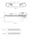
- FIG. 1 is a side view of a thickening machine using the dewatering and thickening belt 1 of the present embodiments.
- the dewatering belt 1 is suspended over two rolls 11 under tension.
- An aqueous solution 12 of paper materials is supplied between the rolls 11 and belt 1 from a material supply port 13.
- a nip pressure between the inner rolls and belt and centrifugal force caused by high speed rotation ink particles, ash content, fibers too minute to form paper, and excess water are removed from the aqueous solution of paper materials continuously.
- materials are supplied uniformly onto a belt in small portions.
- thickening of paper materials such as waste paper, on the other hand, a solid content in the unevenly dispersed form is released on the belt. Uneven imposition of load on the fabric and oblique traveling of the endless belt which is rotating may sometimes lead to deformation and tear of the belt.
- a guide protrusion 4 is disposed in the vicinity of the end portion of a dewatering area of a fabric 2 and, in order to prevent breaking of the fabric at the boundary surface between the guide protrusion 4 and fabric 1, a bending-resistant element 3 is disposed (refer to FIG. 2).
- the bending-resistant element 3 and guide protrusion 4 are fusion bonded to both selvages of the fabric.
- a polyurethane resin sheet which will be the bending-resistant element is overlapped with the fabric on the rough side thereof and melted by thermocompression to allow the resin to penetrate into the fabric, even to the vicinity of the opposite surface of the fabric.
- a guide protrusion 4 obtained by molding of a polyurethane resin is subjected to thermocompression bonding from a side of the fabric opposite to the side to which the sheet is bonded, and these polyurethane resins are fusion bonded into one inside of the fabric.
- the belt of the present embodiments is used for dewatering of an aqueous solution of paper materials so that the fabric used for the belt preferably has an upper layer and lower layer as illustrated in FIG. 2. It is preferred that one of the layers has a dense structure made of yarns having a small diameter so as to enable retention of the fibers thereon, while the other layer has a rough structure made of yarns having a large diameter so as to improve water drainage property and keep the rigidity of the fabric.
- the belt is made of a two-layer fabric using a warp binding yarn for preventing separation between two layers which will otherwise occur by the internal wear of a binding yarn.
- FIGS. 3A and 3B are cross-sectional views illustrating a warp binding yarn pair 5, 6 and a warp pair 7, 8 constituting the fabric of the present embodiments.
- the warp pair 7, 8 is illustrated in FIG. 3B.
- An upper surface side warp 7 and a lower surface side warp 8 illustrated in FIG. 3B are arranged vertically.
- a warp binding yarn pair 5, 6 for weaving upper and lower layers is illustrated in FIG. 3A.
- an upper warp binding yarn 5 for weaving both upper surface side wefts 10 and lower surface side wefts 9 is arranged.
- a lower warp binding yarn 6 for weaving both upper surface side wefts 10 and lower surface side wefts 9 is arranged.
- these two yarns cooperatively function as an upper surface side warp on the upper side surface and function as a lower surface side warp on the lower side surface.
- at least one warp binding yarn pair is disposed in the complete design of a repeating unit of the fabric.
- FIGS. 7, 8 and 9 illustrate cross-sectional views of examples of other fabrics in which embodiments of this invention are employed.
- FIG. 7 is a cross-sectional view illustrating a pair of an upper surface side warp binding yarn 5 and lower surface side warp 8. All of the pairs of warps may use the structure as shown in FIG. 7. Alternatively, the warp pairs illustrated both in FIGS. 7 and 3B may be combined and arranged in a two-layer fabric.
- FIG. 8 is a cross-sectional view illustrating a pair of a lower surface side warp binding yarn 6 and upper surface side warp 7. All of the pairs of warps may use the structure as shown in FIG. 8. Alternatively, the warp pairs illustrated both in FIGS. 8 and 3A/3B may be combined and arranged in a two-layer fabric.
- FIG. 9 is a cross-sectional view illustrating a pair of an upper surface side warp 7 and a lower surface side warp 8, whereto a warp binding yarn 15 is included. All of the pairs of warps may use the structure as shown in FIG. 9.
- the binding yarn 15 simply combines the upper and lower fabrics and does not constitute the surface structure of the fabric. There is no drawback in connection with surface uniformity and other properties using this embodiment of the fabric, as far as this embodiment is used for dehydrating the aqueous solution or concentrating pulp raw material.
- an upper surface side warp or lower surface side warp different in design or function undertakes the tension in the warp direction and stops further breaking of yarns in the warp direction.
- use of a yarn, which is wider and more rigid than an upper surface side warp, as a lower surface side warp contributes to improvement in the anti-breaking effects.
- the bending-resistant element 3 and guide protrusion 4 are fusion-bonded to the both selvages of the fabric.
- a polyurethane resin sheet is fixed to the fabric by melting the sheet and then filling the melted sheet in at least 85% of the space of the fabric. When the percentage is less than 85%, flex-resistant effects are small and the fixing strength is insufficient.
- the sheet is overlapped with the end portion of the fabric. By thermocompression bonding, the resin is penetrated into the fabric sufficiently, even into the vicinity of the surface on the reverse side of the fabric.
- a protrusion obtained by molding a polyurethane resin is attached by thermocompression bonding from the side opposite to the sheet attached side and these polyurethane resins are integrated by fusion bonding inside of the fabric.
- the bending-resistant element is attached so that the outer end portion 3a thereof is located a little outside of the end portion 4a of the fabric in order to prevent fray of yarns and the inner end portion 3b of the bending-resistant element is located so as to slightly overlap with the roll 11.
- the inner end portion 3b of the bending-resistant element is located outside of the roll end portion 11a, stress concentration occurs on the boundary between them, leading to breaking of the fabric thereat.
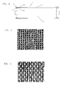
- FIG. 5 is a photograph of the inner surface of the upper side layer of the conventional belt
- FIG. 6 is a photograph of the surface of the inner surface of the upper side layer of the belt of the embodiments.
- Embodiments of the present invention provide a belt for removing ink particles and ash content from an aqueous solution of paper materials regenerated as a result of de-inking or de-ashing of waste paper such as newspaper, dehydrating the aqueous solution or concentrating pulp raw materials. Since it does not cause separation of the fabric, breaking of the fabric, and dropping-off of the guide protrusion, it can be suitably used particularly in a washing machine or thickening machine for dehydrating or thickening of waste paper.
Landscapes
- Life Sciences & Earth Sciences (AREA)
- Engineering & Computer Science (AREA)
- Wood Science & Technology (AREA)
- Woven Fabrics (AREA)
- Paper (AREA)
- Belt Conveyors (AREA)
Applications Claiming Priority (1)
| Application Number | Priority Date | Filing Date | Title |
|---|---|---|---|
| JP2005353401 | 2005-12-07 |
Publications (2)
| Publication Number | Publication Date |
|---|---|
| EP1795647A2 true EP1795647A2 (de) | 2007-06-13 |
| EP1795647A3 EP1795647A3 (de) | 2009-08-26 |
Family
ID=37781997
Family Applications (1)
| Application Number | Title | Priority Date | Filing Date |
|---|---|---|---|
| EP20060256233 Withdrawn EP1795647A3 (de) | 2005-12-07 | 2006-12-07 | Entwässerungs- und Eindickungsband und Verfahren zu seiner Herstellung |
Country Status (5)
| Country | Link |
|---|---|
| US (1) | US20070128414A1 (de) |
| EP (1) | EP1795647A3 (de) |
| CA (1) | CA2570289A1 (de) |
| MX (1) | MXPA06014258A (de) |
| NO (1) | NO20065646L (de) |
Families Citing this family (4)
| Publication number | Priority date | Publication date | Assignee | Title |
|---|---|---|---|---|
| JP4828330B2 (ja) * | 2006-07-07 | 2011-11-30 | 日本フイルコン株式会社 | パルプマシン用プレスファブリック |
| JP6280325B2 (ja) * | 2013-07-12 | 2018-02-14 | 日本フイルコン株式会社 | 工業用二層織物 |
| US11680342B2 (en) | 2016-09-06 | 2023-06-20 | Nippon Filcon Co., Ltd. | Industrial two-layered fabric |
| FI130870B1 (en) * | 2020-06-04 | 2024-04-30 | Valmet Technologies Oy | An industrial textile for manufacturing a fibrous web |
Citations (4)
| Publication number | Priority date | Publication date | Assignee | Title |
|---|---|---|---|---|
| EP0712957A2 (de) | 1994-11-18 | 1996-05-22 | Nippon Filcon Co., Ltd. | Endloses mehrlagiges Gewebe zum Verdichten von Papiermaterialien und Herstellungsverfahren hierfür |
| WO2003071027A1 (en) | 2002-02-15 | 2003-08-28 | Albany International Corp. | A fabric for use in papermaking |
| EP1365066A1 (de) | 2002-05-24 | 2003-11-26 | Nippon Filcon Co., Ltd. | Zweilagiges technisches Gewebe |
| US20040079434A1 (en) | 2002-10-24 | 2004-04-29 | Martin Chad A. | Paired warp triple layer forming fabrics with optimum sheet building characteristics |
Family Cites Families (5)
| Publication number | Priority date | Publication date | Assignee | Title |
|---|---|---|---|---|
| US5039412A (en) * | 1988-05-12 | 1991-08-13 | The Black Clawson Company | Wire with guide belts for a pulp thickener |
| JP3590704B2 (ja) * | 1995-12-13 | 2004-11-17 | 日本フイルコン株式会社 | 紙資料の濃縮用無端状織物およびその製造方法 |
| EP1002892B1 (de) * | 1998-11-18 | 2001-12-19 | Thomas Josef Heimbach Gesellschaft mit beschränkter Haftung & Co. | Textiles Flächengebilde |
| JP3793408B2 (ja) * | 2000-09-26 | 2006-07-05 | 日本フイルコン株式会社 | パルプマシン用プレスファブリック |
| JP4481765B2 (ja) * | 2004-08-23 | 2010-06-16 | 日本フイルコン株式会社 | 工業用二層織物 |
-
2006
- 2006-12-07 US US11/634,940 patent/US20070128414A1/en not_active Abandoned
- 2006-12-07 MX MXPA06014258A patent/MXPA06014258A/es not_active Application Discontinuation
- 2006-12-07 NO NO20065646A patent/NO20065646L/no not_active Application Discontinuation
- 2006-12-07 CA CA 2570289 patent/CA2570289A1/en not_active Abandoned
- 2006-12-07 EP EP20060256233 patent/EP1795647A3/de not_active Withdrawn
Patent Citations (5)
| Publication number | Priority date | Publication date | Assignee | Title |
|---|---|---|---|---|
| EP0712957A2 (de) | 1994-11-18 | 1996-05-22 | Nippon Filcon Co., Ltd. | Endloses mehrlagiges Gewebe zum Verdichten von Papiermaterialien und Herstellungsverfahren hierfür |
| JPH08144185A (ja) | 1994-11-18 | 1996-06-04 | Nippon Filcon Co Ltd | 紙資料の濃縮用無端状多層織物およびその製造方法 |
| WO2003071027A1 (en) | 2002-02-15 | 2003-08-28 | Albany International Corp. | A fabric for use in papermaking |
| EP1365066A1 (de) | 2002-05-24 | 2003-11-26 | Nippon Filcon Co., Ltd. | Zweilagiges technisches Gewebe |
| US20040079434A1 (en) | 2002-10-24 | 2004-04-29 | Martin Chad A. | Paired warp triple layer forming fabrics with optimum sheet building characteristics |
Also Published As
| Publication number | Publication date |
|---|---|
| MXPA06014258A (es) | 2008-10-24 |
| NO20065646L (no) | 2007-01-15 |
| CA2570289A1 (en) | 2007-06-07 |
| US20070128414A1 (en) | 2007-06-07 |
| EP1795647A3 (de) | 2009-08-26 |
Similar Documents
| Publication | Publication Date | Title |
|---|---|---|
| JP2004068168A (ja) | 工業用二層織物 | |
| JP3474039B2 (ja) | 製紙用二層織物 | |
| JP4883629B2 (ja) | 湿紙搬送用ベルト | |
| US8815055B2 (en) | Press felt for papermaking | |
| JP4726487B2 (ja) | 再湿潤しないプレス布 | |
| JP2004036052A (ja) | 工業用二層織物 | |
| JP3397480B2 (ja) | 紙資料の濃縮用無端状多層織物およびその製造方法 | |
| JP2000509772A (ja) | 多軸ピンシームで継ぎ合わされた抄紙機用プレスフェルト | |
| JP3590704B2 (ja) | 紙資料の濃縮用無端状織物およびその製造方法 | |
| EP1795647A2 (de) | Entwässerungs- und Eindickungsband und Verfahren zu seiner Herstellung | |
| JP7377777B2 (ja) | 工業用織物 | |
| CA1262329A (en) | Forming fabric | |
| JP2007182663A (ja) | 脱水、濃縮用ベルトおよびその製造方法 | |
| US7651588B2 (en) | Dewatering and thickening belt having improved guide performance and manufacturing method thereof | |
| JP2004036053A (ja) | 工業用二層織物 | |
| JP3765908B2 (ja) | 故紙等の紙資料の濃縮用無端状織物 | |
| JP4768423B2 (ja) | 脱水、濃縮用ベルトおよびその製造方法 | |
| JP4450488B2 (ja) | 製紙用2層織物 | |
| JP2000170083A (ja) | 製紙面側織物に補助緯糸を配置した製紙用2層織物 | |
| JP2000160493A (ja) | 経糸2重緯糸2重構造の製紙用織物 | |
| JP2000160492A (ja) | 製紙面側織物に補助緯糸を配置した製紙用2層織物 |
Legal Events
| Date | Code | Title | Description |
|---|---|---|---|
| PUAI | Public reference made under article 153(3) epc to a published international application that has entered the european phase |
Free format text: ORIGINAL CODE: 0009012 |
|
| AK | Designated contracting states |
Kind code of ref document: A2 Designated state(s): AT BE BG CH CY CZ DE DK EE ES FI FR GB GR HU IE IS IT LI LT LU LV MC NL PL PT RO SE SI SK TR |
|
| AX | Request for extension of the european patent |
Extension state: AL BA HR MK YU |
|
| PUAL | Search report despatched |
Free format text: ORIGINAL CODE: 0009013 |
|
| AK | Designated contracting states |
Kind code of ref document: A3 Designated state(s): AT BE BG CH CY CZ DE DK EE ES FI FR GB GR HU IE IS IT LI LT LU LV MC NL PL PT RO SE SI SK TR |
|
| AX | Request for extension of the european patent |
Extension state: AL BA HR MK RS |
|
| 17P | Request for examination filed |
Effective date: 20100216 |
|
| 17Q | First examination report despatched |
Effective date: 20100310 |
|
| AKX | Designation fees paid |
Designated state(s): AT BE BG CH CY CZ DE DK EE ES FI FR GB GR HU IE IS IT LI LT LU LV MC NL PL PT RO SE SI SK TR |
|
| GRAP | Despatch of communication of intention to grant a patent |
Free format text: ORIGINAL CODE: EPIDOSNIGR1 |
|
| STAA | Information on the status of an ep patent application or granted ep patent |
Free format text: STATUS: THE APPLICATION IS DEEMED TO BE WITHDRAWN |
|
| 18D | Application deemed to be withdrawn |
Effective date: 20111011 |