EP1795504A1 - Bubblerstein - Google Patents
Bubblerstein Download PDFInfo
- Publication number
- EP1795504A1 EP1795504A1 EP06007145A EP06007145A EP1795504A1 EP 1795504 A1 EP1795504 A1 EP 1795504A1 EP 06007145 A EP06007145 A EP 06007145A EP 06007145 A EP06007145 A EP 06007145A EP 1795504 A1 EP1795504 A1 EP 1795504A1
- Authority
- EP
- European Patent Office
- Prior art keywords
- bubbler
- glass
- gas
- stone
- melt
- Prior art date
- Legal status (The legal status is an assumption and is not a legal conclusion. Google has not performed a legal analysis and makes no representation as to the accuracy of the status listed.)
- Withdrawn
Links
- 239000000919 ceramic Substances 0.000 claims abstract description 3
- 239000007789 gas Substances 0.000 claims description 24
- 239000004575 stone Substances 0.000 claims description 11
- 239000006060 molten glass Substances 0.000 claims description 7
- 239000011449 brick Substances 0.000 abstract 1
- 239000011521 glass Substances 0.000 description 9
- 239000000155 melt Substances 0.000 description 6
- 238000007670 refining Methods 0.000 description 5
- QVGXLLKOCUKJST-UHFFFAOYSA-N atomic oxygen Chemical compound [O] QVGXLLKOCUKJST-UHFFFAOYSA-N 0.000 description 3
- 230000005587 bubbling Effects 0.000 description 3
- 239000000156 glass melt Substances 0.000 description 3
- 230000008018 melting Effects 0.000 description 3
- 238000002844 melting Methods 0.000 description 3
- 238000000034 method Methods 0.000 description 3
- 239000001301 oxygen Substances 0.000 description 3
- 229910052760 oxygen Inorganic materials 0.000 description 3
- XLYOFNOQVPJJNP-UHFFFAOYSA-N water Chemical compound O XLYOFNOQVPJJNP-UHFFFAOYSA-N 0.000 description 3
- UFHFLCQGNIYNRP-UHFFFAOYSA-N Hydrogen Chemical compound [H][H] UFHFLCQGNIYNRP-UHFFFAOYSA-N 0.000 description 2
- 230000001154 acute effect Effects 0.000 description 2
- 239000001257 hydrogen Substances 0.000 description 2
- 229910052739 hydrogen Inorganic materials 0.000 description 2
- MYMOFIZGZYHOMD-UHFFFAOYSA-N Dioxygen Chemical compound O=O MYMOFIZGZYHOMD-UHFFFAOYSA-N 0.000 description 1
- 230000002411 adverse Effects 0.000 description 1
- 230000001174 ascending effect Effects 0.000 description 1
- 238000007664 blowing Methods 0.000 description 1
- 239000000470 constituent Substances 0.000 description 1
- 238000009792 diffusion process Methods 0.000 description 1
- 238000005553 drilling Methods 0.000 description 1
- 239000012467 final product Substances 0.000 description 1
- 150000002484 inorganic compounds Chemical class 0.000 description 1
- 229910010272 inorganic material Inorganic materials 0.000 description 1
- 238000004519 manufacturing process Methods 0.000 description 1
- 230000000630 rising effect Effects 0.000 description 1
- 239000000126 substance Substances 0.000 description 1
Images
Classifications
-
- F—MECHANICAL ENGINEERING; LIGHTING; HEATING; WEAPONS; BLASTING
- F27—FURNACES; KILNS; OVENS; RETORTS
- F27D—DETAILS OR ACCESSORIES OF FURNACES, KILNS, OVENS OR RETORTS, IN SO FAR AS THEY ARE OF KINDS OCCURRING IN MORE THAN ONE KIND OF FURNACE
- F27D3/00—Charging; Discharging; Manipulation of charge
- F27D3/16—Introducing a fluid jet or current into the charge
-
- C—CHEMISTRY; METALLURGY
- C03—GLASS; MINERAL OR SLAG WOOL
- C03B—MANUFACTURE, SHAPING, OR SUPPLEMENTARY PROCESSES
- C03B5/00—Melting in furnaces; Furnaces so far as specially adapted for glass manufacture
- C03B5/16—Special features of the melting process; Auxiliary means specially adapted for glass-melting furnaces
- C03B5/18—Stirring devices; Homogenisation
- C03B5/193—Stirring devices; Homogenisation using gas, e.g. bubblers
-
- C—CHEMISTRY; METALLURGY
- C03—GLASS; MINERAL OR SLAG WOOL
- C03B—MANUFACTURE, SHAPING, OR SUPPLEMENTARY PROCESSES
- C03B5/00—Melting in furnaces; Furnaces so far as specially adapted for glass manufacture
- C03B5/16—Special features of the melting process; Auxiliary means specially adapted for glass-melting furnaces
- C03B5/235—Heating the glass
- C03B5/2356—Submerged heating, e.g. by using heat pipes, hot gas or submerged combustion burners
-
- C—CHEMISTRY; METALLURGY
- C03—GLASS; MINERAL OR SLAG WOOL
- C03B—MANUFACTURE, SHAPING, OR SUPPLEMENTARY PROCESSES
- C03B5/00—Melting in furnaces; Furnaces so far as specially adapted for glass manufacture
- C03B5/16—Special features of the melting process; Auxiliary means specially adapted for glass-melting furnaces
- C03B5/42—Details of construction of furnace walls, e.g. to prevent corrosion; Use of materials for furnace walls
-
- F—MECHANICAL ENGINEERING; LIGHTING; HEATING; WEAPONS; BLASTING
- F23—COMBUSTION APPARATUS; COMBUSTION PROCESSES
- F23M—CASINGS, LININGS, WALLS OR DOORS SPECIALLY ADAPTED FOR COMBUSTION CHAMBERS, e.g. FIREBRIDGES; DEVICES FOR DEFLECTING AIR, FLAMES OR COMBUSTION PRODUCTS IN COMBUSTION CHAMBERS; SAFETY ARRANGEMENTS SPECIALLY ADAPTED FOR COMBUSTION APPARATUS; DETAILS OF COMBUSTION CHAMBERS, NOT OTHERWISE PROVIDED FOR
- F23M5/00—Casings; Linings; Walls
- F23M5/02—Casings; Linings; Walls characterised by the shape of the bricks or blocks used
- F23M5/025—Casings; Linings; Walls characterised by the shape of the bricks or blocks used specially adapted for burner openings
-
- F—MECHANICAL ENGINEERING; LIGHTING; HEATING; WEAPONS; BLASTING
- F27—FURNACES; KILNS; OVENS; RETORTS
- F27D—DETAILS OR ACCESSORIES OF FURNACES, KILNS, OVENS OR RETORTS, IN SO FAR AS THEY ARE OF KINDS OCCURRING IN MORE THAN ONE KIND OF FURNACE
- F27D27/00—Stirring devices for molten material
-
- F—MECHANICAL ENGINEERING; LIGHTING; HEATING; WEAPONS; BLASTING
- F27—FURNACES; KILNS; OVENS; RETORTS
- F27D—DETAILS OR ACCESSORIES OF FURNACES, KILNS, OVENS OR RETORTS, IN SO FAR AS THEY ARE OF KINDS OCCURRING IN MORE THAN ONE KIND OF FURNACE
- F27D3/00—Charging; Discharging; Manipulation of charge
- F27D3/16—Introducing a fluid jet or current into the charge
- F27D2003/162—Introducing a fluid jet or current into the charge the fluid being an oxidant or a fuel
- F27D2003/163—Introducing a fluid jet or current into the charge the fluid being an oxidant or a fuel the fluid being an oxidant
- F27D2003/164—Oxygen
Definitions
- the invention relates to a bubbler for introducing two different gases into a molten glass according to the preamble of claim 1.
- This bubbler is mainly used in the refining of inorganic compounds in molten form, in particular of glass melts.
- the task of lautering is to free the molten glass from physically and chemically bound gases. The gases must be removed so as not to affect the quality of the final product.
- a corresponding bubbler stone is from the DE 100 46 709 A1 known.
- the stone called there bubble dispenser consists of a porous body, which is located at the bottom of the glass pan, and passes so-called mini-gas bubbles in the melt.
- Bubbling with air has been known for many years and is used to specifically influence the glass flow and thus ultimately the glass quality.
- the ascending bubbles transport the surrounding "cold" glass to the surface.
- a device for refining glass in which a bubbler stone is used with two holes through which two different gases are introduced from below into the molten glass.
- the two holes are arranged parallel to each other.
- One bore carries a combustible gas, the other carries oxygen.
- the gas bubbles unite above the bubbler within the gas melt, where the gas components react with each other.
- hydrogen is introduced as a combustible gas, the oxyhydrogen gas reaction takes place, which introduces a relatively large amount of energy.
- the bubbles continue to rise as water vapor.
- the location of the reaction is relatively random and hardly influenced.
- the object of the invention is therefore to propose a technical possibility with which two different gases can be fed into the bottom of a gas melting tank in such a way that the reaction zone can be geometrically defined or varied.
- the bubbler invention is characterized in that the two holes form an acute angle against each other. This can be achieved in that one bore extends straight and the other at an angle, or that both holes are inclined to each other and inclined with respect to the vertical. This ensures that the gases meet at a defined point at which then takes place, for example when using hydrogen and oxygen, the detonating gas reaction.
- the angle between the two holes is larger as 0 °, is preferably between 5 and 40 ° and more preferably between 10 and 20 °.
- one or two displaceable nozzle tubes are provided within the holes, which preferably consist of heat-resistant ceramic. These tube (s) can be pushed in and out, whereby the reaction point can be moved in its height. The reaction can thus be optimally adapted to the requirements of the molten glass.
- the so-called bubbler stone therefore contains at least two bores which are inclined relative to one another at an acute angle, so that their escape directions meet within the glass melt when the bubbler stone is embedded in the bottom of the glass melting tank.
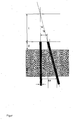
- the figure shows the bubbler stone 2 with the two holes 4 and 6, wherein the bore 4 is executed vertically here and the bore 6 at an angle ⁇ , however, is performed inclined.
- the nozzle tubes 8 and 10 which are longer than the thickness s of the bubbler 2 and which can be moved up and down, whereby their tips can be moved to a certain height g within the glass melt. In this way, the distance of the gas exits t x can be adapted to the gas melting conditions.
- a preferred distance between the nozzles is between 30 and 60 mm. However, distances between 20 and 100 mm are also possible.
- the diameter of the holes 4 or 6 is preferably 15 mm. Some preferred dimensions are given in the following table: Minimum nozzle spacing tx mm 30 Maximum distance to the stone surface G mm 150 Distance of the exits to the stone surface gx mm 63 stone thickness s mm 350 hole spacing sx mm 140 drilling angle ⁇ ° 12.4
- the distance tx thus defines the reaction zone of the exiting and rising gases in the molten glass.
Landscapes
- Engineering & Computer Science (AREA)
- Chemical & Material Sciences (AREA)
- Mechanical Engineering (AREA)
- General Engineering & Computer Science (AREA)
- Materials Engineering (AREA)
- Organic Chemistry (AREA)
- Combustion & Propulsion (AREA)
- Glass Melting And Manufacturing (AREA)
- Glass Compositions (AREA)
- Feeding, Discharge, Calcimining, Fusing, And Gas-Generation Devices (AREA)
Abstract
Die Erfindung betrifft einen Bubblerstein (2) zum Einbringen von zwei unterschiedlichen Gasen in eine Glasschmelze mit mindestens zwei Bohrungen (4, 6). Zur Erhöhung der Variabilität schließen diese einen Winkel α > 0 miteinander ein.
Description
- Die Erfindung betrifft einen Bubblerstein zum Einbringen von zwei unterschiedlichen Gasen in eine Glasschmelze nach dem Oberbegriff des Anspruchs 1.
- Dieser Bubblerstein wird vor allem beim Läutern von anorganischen Verbindungen in geschmolzener Form, insbesondere von Glasschmelzen, eingesetzt. Bei der Herstellung von Glas ist es erforderlich, dem Schmelzprozess einen Läuterprozess nachzuschalten. Dabei hat das Läutern die Aufgabe, das erschmolzene Glas von physikalisch und chemisch gebundenen Gasen zu befreien. Die Gase müssen entfernt werden, um die Qualität des Endproduktes nicht zu beeinträchtigen.
- Neben chemischen Läuterverfahren ist es möglich, Gasbestandteile dadurch aus der Schmelze auszutreiben, dass Gasblasen durch Einblasen eines externen Gases gezielt in die Schmelze eingebracht werden (Düsenblasverfahren, Bubbling) und einen Stoffaustausch bewirken. Aufgrund der Größe der Blasen wird in erster Linie eine Konvektion in der Schmelze erzwungen. Als treibende Kraft für den Stofftransport aus der Schmelze in die Blase wirkt der Konzentrationsunterschied zwischen der in der Schmelze gelösten Gase und der Konzentration des Gases in der Blase. Das Eindiffundieren von gasförmigen Bestandteilen ist mit einem Wachstum der Blase verbunden, das zur Erhöhung der Aufstiegsgeschwindigkeit führt. Ein sehr effektiver Stoffaustausch zwischen Schmelze und Blase wird durch eine große spezifische Oberfläche (sehr viele kleine Blasen) erreicht.
- Ein entsprechender Bubblerstein ist aus der
DE 100 46 709 A1 bekannt. Der dort Blasenspender genannte Stein besteht aus einem Porenkörper, der am Boden der Glaswanne angeordnet ist, und leitet sog. Mini-Gasblasen in die Schmelze. - Bubbling mit Luft ist seit vielen Jahren bekannt und wird zur gezielten Beeinflussung der Glasströmung und damit letztlich der Glasqualität verwendet. Durch die aufsteigenden Bläschen wird das umgebende "kalte" Glas an die Oberfläche transportiert.
- In manchen Fällen kann auch mit reinem Sauerstoff anstelle von Luft gebubbelt werden, wobei man hier, zusätzlich zu der soeben beschriebenen Beeinflussung der Glasströmung, den Einfluss von weiteren Luftbestandteilen neben dem Sauerstoff ausschließen kann.
- Es hat in der Vergangenheit Versuche mit dem Bubbling von Wasserdampf gegeben, die aber nicht erfolgreich waren, da dieser Wasserdampf der Glasschmelze Energie entzieht und sich damit nachteilig auf die Glasqualität auswirkt.
- Aus der
WO 2005/110933 A1 ist eine Vorrichtung zum Läutern von Glas bekannt, bei der ein Bubblerstein mit zwei Bohrungen verwendet wird, über die zwei unterschiedliche Gase von unten in die Glasschmelze eingeführt werden. Die beiden Bohrungen sind parallel zueinander angeordnet. Eine Bohrung führt ein brennbares Gas, die andere führt Sauerstoff. Die Gasblasen vereinigen sich oberhalb des Bubblersteins innerhalb der Gasschmelze, wo die Gasbestandteile miteinander reagieren. Beim Einführen von Wasserstoff als brennbarem Gas erfolgt die Knallgasreaktion, die relativ viel Energie einbringt. Die Blasen steigen als Wasserdampf weiter nach oben. Bei dieser Vorrichtung ist der Ort der Reaktion relativ zufällig und kaum beeinflussbar. - Aufgabe der Erfindung ist es daher, eine technische Möglichkeit vorzuschlagen, mit der zwei verschiedene Gase derart in den Boden einer Gasschmelzwanne zugeführt werden können, dass die Reaktionszone geometrisch definiert oder variiert werden kann.
- Diese Aufgabe wird gelöst mit einem Bubblerstein mit den Merkmalen des Anspruchs 1. Ausgestaltungen der Erfindung sind Gegenstände von Unteransprüchen.
- Der erfindungsgemäße Bubblerstein zeichnet sich dadurch aus, dass die beiden Bohrungen einen spitzen Winkel gegeneinander einschließen. Dies kann dadurch erreicht sein, dass eine Bohrung gerade verläuft und die andere in einem Winkel, oder dass beide Bohrungen zueinander geneigt und geneigt gegenüber der Senkrechten verlaufen. Dadurch wird erreicht, dass die Gase an einem definierten Punkt zusammentreffen, an dem dann, z.B. bei Verwendung von Wasserstoff und Sauerstoff, die Knallgasreaktion stattfindet. Der Winkel zwischen den beiden Bohrungen ist größer als 0 °, liegt bevorzugt zwischen 5 und 40 ° und besonders bevorzugt zwischen 10 und 20°.
- In einer Ausführung der Erfindung sind innerhalb der Bohrungen ein oder zwei verschiebbare Düsenrohre vorgesehen, die bevorzugt aus hitzebeständiger Keramik bestehen. Diese(s) Rohr(e) kann/können ein- und ausgeschoben werden, wodurch der Reaktionspunkt in seiner Höhe verschoben werden kann. Die Reaktion kann damit den Erfordernissen der Glasschmelze bestens angepasst werden. Der sog. Bubblerstein enthält also mindestens zwei Bohrungen, die in einem spitzen Winkel gegeneinander geneigt sind, so dass ihre Fluchtrichtungen sich innerhalb der Glasschmelze treffen, wenn der Bubblerstein in dem Boden der Glasschmelzwanne eingelassen ist.
- Eine Ausführung der Erfindung wird anhand der einzigen Figur gezeigt.
- Die Figur zeigt den Bubblerstein 2 mit den beiden Bohrungen 4 und 6, wobei die Bohrung 4 hier senkrecht ausgeführt ist und die Bohrung 6 in einem Winkel α dagegen geneigt durchgeführt ist. Innerhalb der Bohrungen 4 und 6 befinden sich die Düsenrohre 8 und 10, die länger sind als die Dicke s des Bubblersteins 2 und die nach oben und unten verschoben werden können, wodurch ihre Spitzen auf eine bestimmte Höhe g innerhalb der Glasschmelze verschoben werden können. Auf diese Weise kann der Abstand der Gasaustritte tx den Gasschmelzbedingungen angepasst werden.
- Für die Größen t, gx und α gelten folgende Gleichungen:


- Ein bevorzugter Abstand zwischen den Düsen liegt zwischen 30 und 60 mm. Möglich sind jedoch auch Abstände zwischen 20 und 100 mm. Der Durchmesser der Bohrungen 4 oder 6 liegt bevorzugt bei 15 mm. Einige bevorzugte Maßangaben sind in der folgenden Tabelle enthalten:
Minimaler Düsenabstand tx mm 30 Maximaler Abstand zur Steinoberfläche g mm 150 Abstand der Austritte an der Steinoberfläche gx mm 63 Steindicke s mm 350 Bohrungsabstand sx mm 140 Bohrwinkel α ° 12,4 - Dies führt dazu, dass sich bei unterschiedlichen Düsenabständen tx- unterschiedliche Abstände g der Austrittsstellen zur Steinoberfläche ergeben. Nach folgender Tabelle:
tx' mm 60 50 40 30 g mm 13,6 59,1 105 150 - Der Abstand tx definiert also die Reaktionszone der austretenden und nach oben steigenden Gase in der Glasschmelze.
Claims (3)
- Bubblerstein (2) zum Einbringen von zwei unterschiedlichen Gasen in eine Glasschmelze mit mindestens zwei Bohrungen (4, 6), dadurch gekennzeichnet, dass diese eine Winkel α > 0 miteinander einschließen.
- Bubblerstein (2) nach Anspruch 1, dadurch gekennzeichnet, dass der Winkel α zwischen 5 und 40 °, bevorzugt zwischen 10 und 20 ° liegt.
- Bubblerstein (2) nach einem der vorhergehenden Ansprüche, gekennzeichnet durch eine oder zwei in den Bohrungen (4, 6) verschiebbare Düsenrohre (8, 10) die bevorzugt aus Keramik bestehen.
Priority Applications (5)
| Application Number | Priority Date | Filing Date | Title |
|---|---|---|---|
| US12/093,224 US20090044569A1 (en) | 2005-12-07 | 2006-11-28 | Bubbling brick |
| EP06829167A EP1957417A1 (de) | 2005-12-07 | 2006-11-28 | Bubblerstein |
| BRPI0619505-9A BRPI0619505A2 (pt) | 2005-12-07 | 2006-11-28 | pedra porosa |
| RU2008127266/03A RU2008127266A (ru) | 2005-12-07 | 2006-11-28 | Барботажная вставка |
| PCT/EP2006/011422 WO2007065587A1 (de) | 2005-12-07 | 2006-11-28 | Bubblerstein |
Applications Claiming Priority (1)
| Application Number | Priority Date | Filing Date | Title |
|---|---|---|---|
| DE102005058452A DE102005058452A1 (de) | 2005-12-07 | 2005-12-07 | Bubblerstein |
Publications (1)
| Publication Number | Publication Date |
|---|---|
| EP1795504A1 true EP1795504A1 (de) | 2007-06-13 |
Family
ID=36593719
Family Applications (2)
| Application Number | Title | Priority Date | Filing Date |
|---|---|---|---|
| EP06007145A Withdrawn EP1795504A1 (de) | 2005-12-07 | 2006-04-04 | Bubblerstein |
| EP06829167A Withdrawn EP1957417A1 (de) | 2005-12-07 | 2006-11-28 | Bubblerstein |
Family Applications After (1)
| Application Number | Title | Priority Date | Filing Date |
|---|---|---|---|
| EP06829167A Withdrawn EP1957417A1 (de) | 2005-12-07 | 2006-11-28 | Bubblerstein |
Country Status (7)
| Country | Link |
|---|---|
| US (1) | US20090044569A1 (de) |
| EP (2) | EP1795504A1 (de) |
| BR (1) | BRPI0619505A2 (de) |
| DE (1) | DE102005058452A1 (de) |
| RU (1) | RU2008127266A (de) |
| WO (1) | WO2007065587A1 (de) |
| ZA (1) | ZA200804845B (de) |
Families Citing this family (2)
| Publication number | Priority date | Publication date | Assignee | Title |
|---|---|---|---|---|
| US20110011134A1 (en) * | 2009-07-15 | 2011-01-20 | Richardson Andrew P | Injector for hydrogen and oxygen bubbling in glass baths |
| CN106477852A (zh) * | 2016-09-21 | 2017-03-08 | 巨石集团有限公司 | 一种窑炉鼓泡排布结构 |
Citations (3)
| Publication number | Priority date | Publication date | Assignee | Title |
|---|---|---|---|---|
| US3330645A (en) * | 1962-08-07 | 1967-07-11 | Air Liquide | Method and article for the injection of fluids into hot molten metal |
| US5858059A (en) * | 1997-03-24 | 1999-01-12 | Molten Metal Technology, Inc. | Method for injecting feed streams into a molten bath |
| WO2005110933A1 (de) * | 2004-05-10 | 2005-11-24 | Linde Aktiengesellschaft | Verfahren zum läutern von glas |
Family Cites Families (4)
| Publication number | Priority date | Publication date | Assignee | Title |
|---|---|---|---|---|
| BE756175A (fr) * | 1969-09-16 | 1971-03-15 | Ppg Industries Inc | Appareil de conditionnement du verre dans un bassin |
| US4600425A (en) * | 1985-03-29 | 1986-07-15 | Ppg Industries, Inc. | Bubbler with protective sleeve or fluid coolant jacket |
| ES2159656T3 (es) * | 1995-04-19 | 2001-10-16 | Corning Inc | Procedimiento y dispositivo para fabricar una barra de un material que tiene un gradiente de variacion de composicion en seccion transversal. |
| ATE327208T1 (de) * | 2000-09-01 | 2006-06-15 | Schott Ag | Vorrichtung zum läutern einer glasschmelze |
-
2005
- 2005-12-07 DE DE102005058452A patent/DE102005058452A1/de not_active Withdrawn
-
2006
- 2006-04-04 EP EP06007145A patent/EP1795504A1/de not_active Withdrawn
- 2006-11-28 RU RU2008127266/03A patent/RU2008127266A/ru not_active Application Discontinuation
- 2006-11-28 WO PCT/EP2006/011422 patent/WO2007065587A1/de not_active Ceased
- 2006-11-28 EP EP06829167A patent/EP1957417A1/de not_active Withdrawn
- 2006-11-28 BR BRPI0619505-9A patent/BRPI0619505A2/pt not_active IP Right Cessation
- 2006-11-28 US US12/093,224 patent/US20090044569A1/en not_active Abandoned
-
2008
- 2008-06-04 ZA ZA200804845A patent/ZA200804845B/xx unknown
Patent Citations (3)
| Publication number | Priority date | Publication date | Assignee | Title |
|---|---|---|---|---|
| US3330645A (en) * | 1962-08-07 | 1967-07-11 | Air Liquide | Method and article for the injection of fluids into hot molten metal |
| US5858059A (en) * | 1997-03-24 | 1999-01-12 | Molten Metal Technology, Inc. | Method for injecting feed streams into a molten bath |
| WO2005110933A1 (de) * | 2004-05-10 | 2005-11-24 | Linde Aktiengesellschaft | Verfahren zum läutern von glas |
Also Published As
| Publication number | Publication date |
|---|---|
| WO2007065587A1 (de) | 2007-06-14 |
| DE102005058452A1 (de) | 2007-06-21 |
| US20090044569A1 (en) | 2009-02-19 |
| ZA200804845B (en) | 2009-05-27 |
| EP1957417A1 (de) | 2008-08-20 |
| RU2008127266A (ru) | 2010-01-20 |
| BRPI0619505A2 (pt) | 2011-10-04 |
Similar Documents
| Publication | Publication Date | Title |
|---|---|---|
| DE69924189T2 (de) | Verfahren und vorrichtung zum schmelzen und läutern von glasartigem material | |
| DE4018996C2 (de) | Verfahren und Vorrichtung zur pyrolytischen Bildung einer Oxidbeschichtung auf einer heißen Glasunterlage | |
| EP1127851B1 (de) | Verfahren und Vorrichtung zur Sauerstoffläuterung von Glasschmelzen | |
| DE202020005892U1 (de) | Glasartikel | |
| EP1084996B1 (de) | Verfahren und Vorrichtung zur Herstellung innenvergüteter Glasrohre | |
| DE102004037491B4 (de) | Vorrichtung und Verfahren zum Vorspannen von länglichen, hohlen Gegenständen aus Glas und Verwendung der Vorrichtung | |
| EP2367767B1 (de) | Mehrdüsiger rohrförmiger plasma-abscheidebrenner zur herstellung von vorformen als halbzeuge für optische fasern | |
| DE102016117608A1 (de) | Verfahren und Vorrichtung zur Herstellung von Mikrohohlglaskugeln | |
| EP3686163A1 (de) | Schmelzwanne für die herstellung einer glasschmelze | |
| DE102014101756B4 (de) | Verfahren zur Herstellung von Glasrohren mit einer verbesserten chemischen Beständigkeit sowie Verwendung hiervon | |
| DE1796172A1 (de) | Vorrichtung und Verfahren zur Herstellung von Glasfasern | |
| DE1234948B (de) | Verfahren und Vorrichtungen zur Behandlung von Artikeln aus Glas waehrend ihrer Fabrikation | |
| DE102004020185B4 (de) | Verfahren und Vorrichtung für die Innenbeschichtung von Hohlkörpern sowie Verwendung der Vorrichtung | |
| DE3876519T2 (de) | Verfahren und vorrichtung zum entgasen geschmolzener metalle nach der rh-methode. | |
| DE10200234C1 (de) | Vorrichtung zum Läutern einer Glasschmelze mit einer Unterdruck-Läuterkammer | |
| DE10055969C1 (de) | Verfahren und Vorrichtung zur Läuterung einer Glasschmelze | |
| EP1957417A1 (de) | Bubblerstein | |
| DE10200233C1 (de) | Vorrichtung zum Läutern einer Glasschmelze mit einer Unterdruck-Läuterkammer | |
| EP2253916B1 (de) | Metallurgisches Schmelz- und Behandlungsaggregat | |
| DE60000338T2 (de) | Verfahren zum Herstellen einer Vorform für optische Fasern durch Aussenabscheidung von gegebenfalls dotiertem Siliciumoxid | |
| DE10200232C1 (de) | Vorrichtung zum Läutern einer Glasschmelze in einer Unterdruck-Läuterkammer | |
| DE69402742T2 (de) | Vorrichtung zur Verteilung von pulverförmigen Feststoffen auf ein Substrat zum Zweck seiner Beschichtung | |
| EP1744992B1 (de) | Verfahren zum läutern von glas | |
| DE10138108A1 (de) | Verfahren und Vorrichtung zum Herstellen von Gläsern | |
| EP2106454A1 (de) | Vorrichtung und verfahren zum behandeln von werkblei |
Legal Events
| Date | Code | Title | Description |
|---|---|---|---|
| PUAI | Public reference made under article 153(3) epc to a published international application that has entered the european phase |
Free format text: ORIGINAL CODE: 0009012 |
|
| AK | Designated contracting states |
Kind code of ref document: A1 Designated state(s): AT BE BG CH CY CZ DE DK EE ES FI FR GB GR HU IE IS IT LI LT LU LV MC NL PL PT RO SE SI SK TR |
|
| AX | Request for extension of the european patent |
Extension state: AL BA HR MK YU |
|
| AKX | Designation fees paid | ||
| REG | Reference to a national code |
Ref country code: DE Ref legal event code: 8566 |
|
| STAA | Information on the status of an ep patent application or granted ep patent |
Free format text: STATUS: THE APPLICATION IS DEEMED TO BE WITHDRAWN |
|
| 18D | Application deemed to be withdrawn |
Effective date: 20060405 |