EP1084996B1 - Verfahren und Vorrichtung zur Herstellung innenvergüteter Glasrohre - Google Patents
Verfahren und Vorrichtung zur Herstellung innenvergüteter Glasrohre Download PDFInfo
- Publication number
- EP1084996B1 EP1084996B1 EP00120002A EP00120002A EP1084996B1 EP 1084996 B1 EP1084996 B1 EP 1084996B1 EP 00120002 A EP00120002 A EP 00120002A EP 00120002 A EP00120002 A EP 00120002A EP 1084996 B1 EP1084996 B1 EP 1084996B1
- Authority
- EP
- European Patent Office
- Prior art keywords
- coating
- tube
- glass
- coated
- needle
- Prior art date
- Legal status (The legal status is an assumption and is not a legal conclusion. Google has not performed a legal analysis and makes no representation as to the accuracy of the status listed.)
- Expired - Lifetime
Links
- 239000011521 glass Substances 0.000 title claims description 85
- 238000000034 method Methods 0.000 title claims description 78
- 230000008569 process Effects 0.000 title claims description 56
- 238000000576 coating method Methods 0.000 title claims description 52
- 238000004519 manufacturing process Methods 0.000 title claims description 11
- 239000011248 coating agent Substances 0.000 claims description 50
- 239000000463 material Substances 0.000 claims description 37
- VYPSYNLAJGMNEJ-UHFFFAOYSA-N Silicium dioxide Chemical compound O=[Si]=O VYPSYNLAJGMNEJ-UHFFFAOYSA-N 0.000 claims description 15
- 238000009792 diffusion process Methods 0.000 claims description 13
- 238000007664 blowing Methods 0.000 claims description 6
- 239000011148 porous material Substances 0.000 claims description 6
- 238000003280 down draw process Methods 0.000 claims description 2
- MCMNRKCIXSYSNV-UHFFFAOYSA-N Zirconium dioxide Chemical compound O=[Zr]=O MCMNRKCIXSYSNV-UHFFFAOYSA-N 0.000 claims 16
- PNEYBMLMFCGWSK-UHFFFAOYSA-N aluminium oxide Inorganic materials [O-2].[O-2].[O-2].[Al+3].[Al+3] PNEYBMLMFCGWSK-UHFFFAOYSA-N 0.000 claims 5
- 229910052681 coesite Inorganic materials 0.000 claims 5
- 229910052593 corundum Inorganic materials 0.000 claims 5
- 229910052906 cristobalite Inorganic materials 0.000 claims 5
- 239000000377 silicon dioxide Substances 0.000 claims 5
- 229910052682 stishovite Inorganic materials 0.000 claims 5
- 229910052905 tridymite Inorganic materials 0.000 claims 5
- 229910001845 yogo sapphire Inorganic materials 0.000 claims 5
- 238000009434 installation Methods 0.000 claims 3
- 239000000126 substance Substances 0.000 description 15
- 239000007789 gas Substances 0.000 description 9
- 238000000465 moulding Methods 0.000 description 9
- 239000011265 semifinished product Substances 0.000 description 8
- 229910004298 SiO 2 Inorganic materials 0.000 description 7
- 239000003513 alkali Substances 0.000 description 7
- 238000002844 melting Methods 0.000 description 6
- KKCBUQHMOMHUOY-UHFFFAOYSA-N Na2O Inorganic materials [O-2].[Na+].[Na+] KKCBUQHMOMHUOY-UHFFFAOYSA-N 0.000 description 5
- 239000002253 acid Substances 0.000 description 5
- 229910018072 Al 2 O 3 Inorganic materials 0.000 description 4
- XKRFYHLGVUSROY-UHFFFAOYSA-N Argon Chemical compound [Ar] XKRFYHLGVUSROY-UHFFFAOYSA-N 0.000 description 4
- 238000002386 leaching Methods 0.000 description 4
- 230000008018 melting Effects 0.000 description 4
- 239000000203 mixture Substances 0.000 description 4
- 239000000047 product Substances 0.000 description 4
- 239000000243 solution Substances 0.000 description 4
- 239000005341 toughened glass Substances 0.000 description 4
- 239000005407 aluminoborosilicate glass Substances 0.000 description 3
- 238000010276 construction Methods 0.000 description 3
- 238000001035 drying Methods 0.000 description 3
- 239000000156 glass melt Substances 0.000 description 3
- 230000003301 hydrolyzing effect Effects 0.000 description 3
- 238000007493 shaping process Methods 0.000 description 3
- 239000007921 spray Substances 0.000 description 3
- 238000012360 testing method Methods 0.000 description 3
- 230000004580 weight loss Effects 0.000 description 3
- 241000196324 Embryophyta Species 0.000 description 2
- 229910052782 aluminium Inorganic materials 0.000 description 2
- 229910052786 argon Inorganic materials 0.000 description 2
- 230000015572 biosynthetic process Effects 0.000 description 2
- 239000007795 chemical reaction product Substances 0.000 description 2
- 230000000694 effects Effects 0.000 description 2
- 238000005755 formation reaction Methods 0.000 description 2
- 229910052736 halogen Inorganic materials 0.000 description 2
- 150000002367 halogens Chemical class 0.000 description 2
- 230000006872 improvement Effects 0.000 description 2
- 229910052748 manganese Inorganic materials 0.000 description 2
- 239000006060 molten glass Substances 0.000 description 2
- 238000004806 packaging method and process Methods 0.000 description 2
- 239000002245 particle Substances 0.000 description 2
- 238000000623 plasma-assisted chemical vapour deposition Methods 0.000 description 2
- 229910052710 silicon Inorganic materials 0.000 description 2
- 229910052596 spinel Inorganic materials 0.000 description 2
- 239000011029 spinel Substances 0.000 description 2
- 238000010998 test method Methods 0.000 description 2
- 238000004448 titration Methods 0.000 description 2
- 238000005406 washing Methods 0.000 description 2
- 239000004563 wettable powder Substances 0.000 description 2
- 229910000505 Al2TiO5 Inorganic materials 0.000 description 1
- 241000234282 Allium Species 0.000 description 1
- 235000002732 Allium cepa var. cepa Nutrition 0.000 description 1
- RYGMFSIKBFXOCR-UHFFFAOYSA-N Copper Chemical compound [Cu] RYGMFSIKBFXOCR-UHFFFAOYSA-N 0.000 description 1
- YCKRFDGAMUMZLT-UHFFFAOYSA-N Fluorine atom Chemical compound [F] YCKRFDGAMUMZLT-UHFFFAOYSA-N 0.000 description 1
- UFHFLCQGNIYNRP-UHFFFAOYSA-N Hydrogen Chemical compound [H][H] UFHFLCQGNIYNRP-UHFFFAOYSA-N 0.000 description 1
- 229910020068 MgAl Inorganic materials 0.000 description 1
- 238000004847 absorption spectroscopy Methods 0.000 description 1
- 239000005354 aluminosilicate glass Substances 0.000 description 1
- 239000002585 base Substances 0.000 description 1
- 239000006121 base glass Substances 0.000 description 1
- 230000008901 benefit Effects 0.000 description 1
- 239000005388 borosilicate glass Substances 0.000 description 1
- 229910010293 ceramic material Inorganic materials 0.000 description 1
- -1 chamotte Inorganic materials 0.000 description 1
- 230000008859 change Effects 0.000 description 1
- 238000005234 chemical deposition Methods 0.000 description 1
- 238000006243 chemical reaction Methods 0.000 description 1
- 238000005229 chemical vapour deposition Methods 0.000 description 1
- 230000001427 coherent effect Effects 0.000 description 1
- 150000001875 compounds Chemical class 0.000 description 1
- 229910052802 copper Inorganic materials 0.000 description 1
- 239000010949 copper Substances 0.000 description 1
- 229910052878 cordierite Inorganic materials 0.000 description 1
- 230000003247 decreasing effect Effects 0.000 description 1
- JSKIRARMQDRGJZ-UHFFFAOYSA-N dimagnesium dioxido-bis[(1-oxido-3-oxo-2,4,6,8,9-pentaoxa-1,3-disila-5,7-dialuminabicyclo[3.3.1]nonan-7-yl)oxy]silane Chemical compound [Mg++].[Mg++].[O-][Si]([O-])(O[Al]1O[Al]2O[Si](=O)O[Si]([O-])(O1)O2)O[Al]1O[Al]2O[Si](=O)O[Si]([O-])(O1)O2 JSKIRARMQDRGJZ-UHFFFAOYSA-N 0.000 description 1
- KZHJGOXRZJKJNY-UHFFFAOYSA-N dioxosilane;oxo(oxoalumanyloxy)alumane Chemical compound O=[Si]=O.O=[Si]=O.O=[Al]O[Al]=O.O=[Al]O[Al]=O.O=[Al]O[Al]=O KZHJGOXRZJKJNY-UHFFFAOYSA-N 0.000 description 1
- 238000004090 dissolution Methods 0.000 description 1
- 238000009826 distribution Methods 0.000 description 1
- 239000003814 drug Substances 0.000 description 1
- 229940079593 drug Drugs 0.000 description 1
- 238000005516 engineering process Methods 0.000 description 1
- 230000007613 environmental effect Effects 0.000 description 1
- 238000002474 experimental method Methods 0.000 description 1
- 238000011049 filling Methods 0.000 description 1
- 229910052731 fluorine Inorganic materials 0.000 description 1
- 239000011737 fluorine Substances 0.000 description 1
- 230000036541 health Effects 0.000 description 1
- 239000001307 helium Substances 0.000 description 1
- 229910052734 helium Inorganic materials 0.000 description 1
- SWQJXJOGLNCZEY-UHFFFAOYSA-N helium atom Chemical compound [He] SWQJXJOGLNCZEY-UHFFFAOYSA-N 0.000 description 1
- 239000001257 hydrogen Substances 0.000 description 1
- 229910052739 hydrogen Inorganic materials 0.000 description 1
- 229910010272 inorganic material Inorganic materials 0.000 description 1
- 239000011147 inorganic material Substances 0.000 description 1
- 238000011068 loading method Methods 0.000 description 1
- CPLXHLVBOLITMK-UHFFFAOYSA-N magnesium oxide Inorganic materials [Mg]=O CPLXHLVBOLITMK-UHFFFAOYSA-N 0.000 description 1
- 238000005259 measurement Methods 0.000 description 1
- 239000000155 melt Substances 0.000 description 1
- 238000010327 methods by industry Methods 0.000 description 1
- 229910052863 mullite Inorganic materials 0.000 description 1
- 150000004767 nitrides Chemical class 0.000 description 1
- 230000003287 optical effect Effects 0.000 description 1
- RVTZCBVAJQQJTK-UHFFFAOYSA-N oxygen(2-);zirconium(4+) Chemical compound [O-2].[O-2].[Zr+4] RVTZCBVAJQQJTK-UHFFFAOYSA-N 0.000 description 1
- 238000005268 plasma chemical vapour deposition Methods 0.000 description 1
- 239000000843 powder Substances 0.000 description 1
- 239000010970 precious metal Substances 0.000 description 1
- 238000012545 processing Methods 0.000 description 1
- AABBHSMFGKYLKE-SNAWJCMRSA-N propan-2-yl (e)-but-2-enoate Chemical compound C\C=C\C(=O)OC(C)C AABBHSMFGKYLKE-SNAWJCMRSA-N 0.000 description 1
- 239000002994 raw material Substances 0.000 description 1
- 230000009467 reduction Effects 0.000 description 1
- 238000000926 separation method Methods 0.000 description 1
- 229910052814 silicon oxide Inorganic materials 0.000 description 1
- 229910052851 sillimanite Inorganic materials 0.000 description 1
- 238000005245 sintering Methods 0.000 description 1
- 239000005361 soda-lime glass Substances 0.000 description 1
- 238000006557 surface reaction Methods 0.000 description 1
- 239000002341 toxic gas Substances 0.000 description 1
- 238000012549 training Methods 0.000 description 1
- 230000009466 transformation Effects 0.000 description 1
- WFKWXMTUELFFGS-UHFFFAOYSA-N tungsten Chemical compound [W] WFKWXMTUELFFGS-UHFFFAOYSA-N 0.000 description 1
- 229910052721 tungsten Inorganic materials 0.000 description 1
- 239000010937 tungsten Substances 0.000 description 1
- XLYOFNOQVPJJNP-UHFFFAOYSA-N water Substances O XLYOFNOQVPJJNP-UHFFFAOYSA-N 0.000 description 1
- 229910001928 zirconium oxide Inorganic materials 0.000 description 1
- GFQYVLUOOAAOGM-UHFFFAOYSA-N zirconium(iv) silicate Chemical compound [Zr+4].[O-][Si]([O-])([O-])[O-] GFQYVLUOOAAOGM-UHFFFAOYSA-N 0.000 description 1
Images
Classifications
-
- C—CHEMISTRY; METALLURGY
- C03—GLASS; MINERAL OR SLAG WOOL
- C03B—MANUFACTURE, SHAPING, OR SUPPLEMENTARY PROCESSES
- C03B17/00—Forming molten glass by flowing-out, pushing-out, extruding or drawing downwardly or laterally from forming slits or by overflowing over lips
- C03B17/04—Forming tubes or rods by drawing from stationary or rotating tools or from forming nozzles
-
- C—CHEMISTRY; METALLURGY
- C03—GLASS; MINERAL OR SLAG WOOL
- C03C—CHEMICAL COMPOSITION OF GLASSES, GLAZES OR VITREOUS ENAMELS; SURFACE TREATMENT OF GLASS; SURFACE TREATMENT OF FIBRES OR FILAMENTS MADE FROM GLASS, MINERALS OR SLAGS; JOINING GLASS TO GLASS OR OTHER MATERIALS
- C03C17/00—Surface treatment of glass, not in the form of fibres or filaments, by coating
- C03C17/001—General methods for coating; Devices therefor
- C03C17/003—General methods for coating; Devices therefor for hollow ware, e.g. containers
- C03C17/004—Coating the inside
-
- Y—GENERAL TAGGING OF NEW TECHNOLOGICAL DEVELOPMENTS; GENERAL TAGGING OF CROSS-SECTIONAL TECHNOLOGIES SPANNING OVER SEVERAL SECTIONS OF THE IPC; TECHNICAL SUBJECTS COVERED BY FORMER USPC CROSS-REFERENCE ART COLLECTIONS [XRACs] AND DIGESTS
- Y10—TECHNICAL SUBJECTS COVERED BY FORMER USPC
- Y10S—TECHNICAL SUBJECTS COVERED BY FORMER USPC CROSS-REFERENCE ART COLLECTIONS [XRACs] AND DIGESTS
- Y10S65/00—Glass manufacturing
- Y10S65/09—Tube
Definitions
- the invention relates to methods for producing internally tempered glass tubes and Devices for performing the method.
- Semi-finished glass tubes made of silica glass can therefore not be used with sufficient Manufacture quality and economy for mass applications.
- melting glasses used e.g. B. borosilicate glasses or soda-lime glasses.
- soda-lime glasses As a tube, these can advantageously be produced and formed economically.
- a corresponding aggressive gas typically SO 2 or HCl gas
- SO 2 or HCl gas is introduced into the still hot glass tube, which leads to surface reactions and a reduction in the alkali content in the surface.
- Such entalkalizing processes are e.g. B. described in H.A. Schaeffer et. al .; Glastechn. Ber. 54 (1981) No. 8, pp. 247-256.
- the disadvantages of these methods are that predominantly toxic gases are used, the Glass surface after chemical treatment still traces of this aggressive May contain reaction gases and that the glass surface structure is damaged becomes what leads to an increased surface area and to active centers of the Surfaces. Furthermore, the use of such aggressive gases is over Environmental and health and safety conditions are unfavorable. When reshaping Such leached glass tubes can detach particles come out of the porous, damaged surface. It is also before use the leached glass tubes a washing process to remove the Reaction products necessary. This washing process does a subsequent one Drying and disposal of the reaction products necessary, d. H. increases the Cost of manufacturing the semi-finished glass tubes.
- tubular glass containers made of low-melting glass which serve in particular as packaging for pharmaceutical materials, on their inner surface with a silicon oxide (SiO 2 ) layer, which in their Inertness is equivalent to a quartz glass surface
- SiO 2 silicon oxide
- PECVD Plasma enhanced chemical vapor deposition
- PICVD plasma pulse-chemical-vapor Deposition
- the invention is based on the object, glass tubes, the semi-finished products represent for the various hollow glass moldings, in a simple manner to temper on their inner surface.
- a coated drawing tool is used, for example when Danner process a coated Danner pipe or in the Vello process a coated Vello needle, the coating of which comes into contact with the inner one Surface of the resulting pipe coating material on the glass surface emits.
- This "doping" creates the inner surface of the pipe hardened and tempered. It is passivated and has an increased chemical resistance on.
- the release of coating material should be such that at least 1.5 ⁇ g / (m 2 ⁇ s) of the coating area are released from the coating. This is guaranteed by the material used and its surface quality.
- Suitable coating materials are inorganic materials, e.g. B. nitrides or preferably oxides which are themselves sufficiently inert against water, acid or alkali attack and at which at the temperatures and viscosities in this process step (about 700 ° C - 1400 ° C and about 10 3.3 dPas - 10 7.3 dPas) sufficient diffusion and dissolution processes occur at the coating / glass interface. Glasses with a transformation temperature T g ⁇ 500 ° C result in only very small amounts of diffusion and solution due to the low process temperatures and there is no significant enrichment of the coating material on the inner tube surface.
- Preferred materials have diffusion coefficients of at least 1 ⁇ 10 -13 m 2 / s at the application temperature.
- the diffusion coefficients specified for the materials relate to a temperature interval of 800 ° C to 1200 ° C, which is in the range of the application temperatures (see above: temperatures during the process step): z. B.
- ZrO 2 ⁇ 3.8 ⁇ 10 -11 ; with concentrations of 0.1-5% by weight of RN, R 3 N 4 , RO 2 , RO, R 2 O 3 (where R is for Y, Ca, Mg, K, Si, Al, B, Ti, Mn , Co and similar elements)) doped SiO 2 : ⁇ 7.7 ⁇ 10 -11 ; Al 2 O 3 : ⁇ 1 ⁇ 10 -13 : ZrO 2 , Al 2 O 3 , SiO 2 , MgO and mixtures thereof, mullite, mixtures of the oxides mentioned with 0.1-20% by weight RO 2 are particularly suitable, RO, R 2 O 3 , RN, R 3 N 4 (where R is Y, Ca, Mg, K, Si, Al, B, Ti, Mn, Co and similar elements), e.g. B. with Y 2 O 3 or spinel (MgAl 2 O 4 ). Coatings made of ZrO 2 or with proportions of ZrO 2, in particular with proportions
- the coating can be applied to the drawing tool using customary methods, i. a. made of ceramic materials such as chamotte, sillimanite, zirconium oxide, zirconium silicate, Spinel, cordierite, aluminum titanate, or metallic Layers or metallic base bodies with a permanent temperature resistance of at least 1250 ° C are applied.
- customary methods i. a. made of ceramic materials such as chamotte, sillimanite, zirconium oxide, zirconium silicate, Spinel, cordierite, aluminum titanate, or metallic Layers or metallic base bodies with a permanent temperature resistance of at least 1250 ° C are applied.
- customary methods i. a. made of ceramic materials such as chamotte, sillimanite, zirconium oxide, zirconium silicate, Spinel, cordierite, aluminum titanate, or metallic Layers or metallic base bodies with a permanent temperature resistance of at least 1250 ° C are applied.
- LPPS Low pressure plasma sprayed
- the main element of every plasma coating system is the plasma spray gun.
- Part of the plasma spray gun are tungsten electrodes and concentric with them arranged copper nozzles.
- To generate the plasma between An arc ignited the cathode and anode (nozzle). It will Gas supplied concentrically to the cathode (often a mixture of argon and helium or hydrogen) ionized and extremely strongly heated (average gas temperature approx. 10,000 K). The highly heated gas is accelerated and forms outside the plasma spray gun the plasma flame.
- a conveying gas (often argon). It will Speeds of several 100 m / s reached. When hitting the Drawing tools solidify the wettable powder particles and form coherent ones Layers.
- the open one Pore space of the coating zone should be more than 10%, preferably at least 15%.
- I. a. will produce layer thicknesses between 10 ⁇ m and 2000 ⁇ m. Layer thicknesses of 10 ⁇ m are already sufficient.
- the large surface area that is essential for achieving a sufficient effect can also be described by the specific surface area [m 2 / kg of coating agent] instead of by the porosity. It should be at least 50 m 2 / kg, preferably 75 m 2 / kg.
- the method according to the invention can be applied to all tube drawing methods which use a drawing tool which serves to form the tube cavity or supports it. These are known and proven tube drawing processes, of which the most common are briefly outlined:
- the glass melt already flows out of the pipe Feeder as it exits through a cylindrical nozzle.
- the melt overflows a dome, the Vello needle, the corresponding drawing tool for this process.
- the glass is formed into a tube.
- the tube first flows vertically downwards, then is in the Redirected horizontally and, like in the Danner process, via a roller conveyor peeled, chilled and cut.
- the glass melt also flows in the A-draw process (down-draw process) already in tube form from the feeder because of its cylindrical shape exit. It flows over the drawing tool, a dome, here the A-pulling needle, where the glass is formed into a tube. This procedure can work with air become.
- the pipe flows vertically downwards and is without deflection cut to length at temperatures of approx. 300 ° C.
- needle body is used in both the Vello and A-Zug processes but also the up to 2 m long holding shaft coated. Both needle bodies as well as holding shaft are here under the term needle or general Drawing tool used together.
- the Danner method is particularly good for the method according to the invention suitable.
- the dwell times for the Vello and A-Zug processes are only 30 to 50% of it.
- the device according to the invention is characterized in that one known device for pulling glass tubes with known Device parts has a coated drawing tool, the coating in contact with the inner surface of the resulting glass tube Releases coating material to the glass surface.
- a special device according to the invention with a pipe drawing system according to Danner is characterized in that an inclined, rotatable, rotationally symmetrical, coated pipe is arranged in it. So that sufficient material is released from the coating on the inner glass surface when the glass tube is pulled, the coating material, which preferably contains ZrO 2 and / or SiO 2 and / or Al 2 O 3 and / or MgO, preferably has a diffusion coefficient of at least 1 ⁇ 10 -13 m 2 / s.
- the preferred materials and their surface properties and layer thicknesses are mentioned in the process description.
- Such a device for pipe drawing according to Danner also has one Nozzle from which the glass runs from the feeder channel onto the pipe. Further it has a furnace, for example a gas-heated muffle furnace, for adjustment a temperature gradient between the outlet from the nozzle and the end of the pipe as well as a blowing device for loading the interior of the glass tube to be removed with an overpressure or underpressure the ambient pressure.
- a furnace for example a gas-heated muffle furnace, for adjustment a temperature gradient between the outlet from the nozzle and the end of the pipe as well as a blowing device for loading the interior of the glass tube to be removed with an overpressure or underpressure the ambient pressure.
- the temperature difference between the outlet from the nozzle and the pipe end, depending on the type of glass and the pipe to be manufactured, is around 400 K.
- the viscosity range between the outlet of the nozzle and the pipe end is 10 3.3 regardless of the type of glass up to 10 5.9 dPas depending on the pipe to be manufactured.
- a special device according to the invention with a pipe drawing system according to Vello or an A-train pipe drawing system is characterized in that a coated pipe drawing needle is arranged vertically in it.
- the same materials and layer thicknesses as described above are preferred as the coating.
- Its diffusion coefficient is preferably at least 1 ⁇ 10 -13 m 2 / s.
- It also has a preferably electrically heated muffle for controlling the deformation temperature and a blowing device for applying an overpressure or underpressure to the interior of the glass tube to be removed.
- the system according to Vello has a deflection device with which the glass tube is deflected into the horizontal in the plastic state.
- the properties and preferred designs with regard to material, material release and diffusion coefficient correspond to those of the porous coating of a drawing tool in the case of a porous drawing tool.
- a drawing tool made of ZrO 2 or Sillimanit is preferably used.
- the drawing tool should have a porosity, ie an open pore space of at least 10%.
- porous bodies can be produced, for example, by sintering.
- the Danner process using a porous pipe for example made of ZrO 2 or Sillimanit, is particularly suitable for this process with a porous drawing tool.
- the representation on the device is that of the shaping serves, limited; the usual not shown close each Components drawing channel with drawing track and drawing machine with separating device.
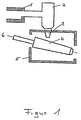
- FIG. 1 shows the distributor 1 and crucible 2 containing the glass melt in the tube drawing system according to Danner.
- the molten glass emerges from the latter through the nozzle 3 as a continuous strand and meets the drawing tool, the inclined coated rotating pipe 4.
- the pipe and the outlet The nozzle is located in an oven 5, which ensures a temperature gradient between the outlet from the nozzle and the end of the pipe.
- a blowing device 6 serves to pressurize the interior of the glass tube to be drawn off with overpressure relative to the ambient pressure. The glass is pulled off the pipe and (not shown) redirected into the horizontal.
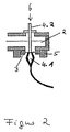
- the glass emerges from the crucible 2 through the cylindrical nozzle 3 onto the vertical Vello needle 4 with the needle body 4.1 and the needle shaft 4.2.
- the nozzle is in the muffle 5.
- the tube flowing vertically from the needle is deflected into the horizontal and pulled off.
- the glass emerges from a crucible 2 through a like in FIG cylindrical nozzle 3 on a vertical A-pull needle 4. It is located in a muffle 5. Blown air is also fed in at position 6 through the needle 4. In contrast to the Vello process, the needle remains vertical drain pipe in vertical direction.
- the tubes drawn in this way have a ZrO 2 content of 3.5% by weight on their inner surface, which drops to a depth of 0.1 mm in the interior of the glass to 0.3% by weight.
- concentration doses measured by SIMS represent the respective relative difference to the base glass.
- the aluminoborosilicate glass processed under 1) in tubes (75% by weight SiO 2 , 11 B 2 O 3 ; 5 Al 2 O 3 ; 7 Na 2 O; 0.5 BaO, 1.5 CaO) also exhibits without the treatment according to the invention already very good chemical resistance, namely a hydrolytic resistance according to DIN 52339 - ISO 4802 of hydrolytic class 1, an acid resistance according to ISO 11776 of acid class 1 and an alkali resistance according to ISO 695 of alkali class 2.
- a further improvement of the already very good chemical resistance has among other things, the advantage that the glass when processing into products such. B. ampoules can be exposed to higher temperatures without exceeding leaching limits.
- a semi-finished product (or semi-finished product) is known to be a semi-finished product, one Goods between raw materials and finished product, the different manufacturing stages behind, but has to go through more.
- Such forming processes are e.g. B. Processes in which tapering, melting, Formations are attached, for. B. to put them together, to close them, to connect etc.
- Hollow glass moldings with a rather low degree of shaping are e.g. B. cylindrical body made from the semi-finished product by hot or cold forming are, and ultimately only "processed" on their end faces Need to become.
- Such glass moldings are, for example, syringe cylinders.
- Hollow glass moldings with a higher degree of formation are such.
Landscapes
- Chemical & Material Sciences (AREA)
- Engineering & Computer Science (AREA)
- Materials Engineering (AREA)
- Organic Chemistry (AREA)
- Life Sciences & Earth Sciences (AREA)
- Chemical Kinetics & Catalysis (AREA)
- General Chemical & Material Sciences (AREA)
- Geochemistry & Mineralogy (AREA)
- Glass Compositions (AREA)
Description
- für den chemischen Anlagenbau
- die für Durchflußmesser für chemische aggressive Medien verwendet werden
- für analytische Zwecke (z. B. Bürettenröhren, Titrationszylinder, etc.)
- für Reagenzgläser für spezielle Zwecke
- für Ummantelungen von Meßelektroden in aggressiven Medien
- für Beleuchtungszwecke, z. B. Halogenlampen
- für Entladungslampen
- die als Komponenten für biotechnologische Reaktoren eingesetzt werden, und
- die als Behälter für medizinische Zwecke (z. B. Ampullen, Fläschchen, Spritzenkörper, Zylinderampullen, etc.) verwendet werden
- die spezifischen Pfeifenbelastung in kg/m2 × h
- die Energieeinbringung im gasbeheizten Muffelofen
- die Größe des Muffelofens
- die Wärmeleitfähigkeit des Materials der Dannerpfeife
- das Material des Muffelofens
- die Gesamtkonstruktion der Pfeife
Beispiel: Eine mit 93 Gew.-% ZrO2 und 7 Gew.-% Y2O3 beschichtete Ziehnadel mit einer Beschichtungsdicke von 400 µm wurde 28 Tage bei Temperaturen von 1240 °C bei einem Aluminosilikatglas mit einem Glasdurchsatz von ca. 5000 kg/Tag gefahren. Nach dieser Zeit lag eine Abnahme der Beschichtungsdicke von ca. 20 µm (entspricht ca. 5 %) vor. Daraus läßt sich eine Standzeit von ca. 500 Tagen hochrechnen. Die Standzeit von Edelmetallbauteilen liegt im Mittel bei ca. 1 Jahr.
- Figur 1
- zeigt schematisch den Aufbau einer Vorrichtung mit einer Rohrziehanlage nach Danner.
- Figur 2
- zeigt schematisch den Aufbau einer Vorrichtung mit einer Rohrziehanlage nach Vello.
Das Glas wird von der Pfeife abgezogen und (nicht mehr eingezeichnet) in die Horizontale umgelenkt.
Das von der Nadel senkrecht abfließende Rohr wird in die Horizontale umgelenkt und abgezogen.
| A | V | |
| Na-Auslaugung | 2.22 ppm Na2O | 2.37 ppm Na2O |
| Klasse | 1 | 1 |
| A | V | |
| Na - Auslaugung | 0,066 mg Na2O/dm2 | 0,075 mg Na2O/dm2 |
| A | V | |
| Gewichtsverlust | 43 mg/dm2 | 50 mg/dm2 |
Mit dem Verfahren gemäß der Erfindung gelingt es also, Glasrohre zur Verfügung zu stellen, deren innere Oberfläche vergütet ist, so daß sie als Halbzeug für hohle Glasformkörper geeignet sind, an die hohe Anforderungen bezüglich der chemischen Beständigkeit ihrer inneren Oberfläche gestellt werden.
- Behälter für medizinische Zwecke wie Ampullen, Fläschchen, Spritzenkörpem, Zylinderampullen.
- Lampenkolben, insbesondere Lampenkolben für Halogenlampen
- Reagenzgläsern, Büretten, Pipetten, Titrationszylindern
- röhrenförmigen Teilen für den chemischen Anlagenbau, Komponenten für biotechnologische Reaktoren
Claims (26)
- Verfahren zur Herstellung innenvergüteter Glasrohre,
dadurch gekennzeichnet, daß bei einem an sich bekannten Rohrziehverfahren zur Herstellung von Glasrohren ein beschichtetes Ziehwerkzeug verwendet wird, dessen Beschichtung bei Kontakt mit der Innenoberfläche des entstehenden Rohres Beschichtungsmaterial abgibt und an der inneren Glasoberfläche anreichert. - Verfahren nach Anspruch 1,
dadurch gekennzeichnet, daß ein Ziehwerkzeug verwendet wird, dessen Beschichtung wenigstens 1,5 µg/(m2 × s) an Beschichtungsmaterial abgibt. - Verfahren nach Anspruch 1 oder 2,
dadurch gekennzeichnet, daß ein Ziehwerkzeug verwendet wird, dessen Beschichtung eine spezifische Oberfläche von wenigstens 50 m2/kg aufweist. - Verfahren nach Anspruch 1 oder 2,
dadurch gekennzeichnet, daß ein Ziehwerkzeug verwendet wird, dessen Beschichtung einen offenen Porenraum von mehr als 10 % aufweist. - Verfahren nach wenigstens einem der Ansprüche 1 bis 4,
dadurch gekennzeichnet, daß es sich bei dem Rohrziehverfahren um ein Verfahren nach Danner handelt, bei dem eine beschichtete Pfeife verwendet wird. - Verfahren nach wenigstens einem der.Ansprüche 1 bis 4,
dadurch gekennzeichnet, daß es sich bei dem Rohrziehverfahren um ein Verfahren nach Vello handelt, bei dem eine beschichtete Nadel verwendet wird. - Verfahren nach wenigstens einem der Ansprüche 1 bis 4,
dadurch gekennzeichnet, daß es sich bei dem Rohrziehverfahren um ein A-Zug-Verfahren handelt, bei dem eine beschichtete Nadel verwendet wird. - Verfahren nach wenigstens einem der Ansprüche 1 bis 7,
dadurch gekennzeichnet, daß ein beschichtetes Ziehwerkzeug verwendet wird, dessen Beschichtungsmaterial bei den Anwendungstemperaturen einen Diffusionskoeffizienten von wenigstens 1 × 10-13 m2/s besitzt. - Verfahren nach wenigstens einem der Ansprüche 1 bis 8,
dadurch gekennzeichnet, daß ein Ziehwerkzeug verwendet wird, dessen Beschichtung ZrO2 und /oder Al2O3 und/oder SiO2 und/oder MgO enthält. - Verfahren nach Anspruch 9,
dadurch gekennzeichnet, daß ein beschichtetes Ziehwerkzeug verwendet wird, dessen Beschichtung ZrO2 enthält. - Vorrichtung zur Herstellung innenvergüteter Glasrohre nach dem Verfahren gemäß Anspruch 5
miteiner Rohrziehanlage nach Danner, in der eine geneigte, drehbare, rotationssymmetrische, beschichtete Pfeife angeordnet ist, deren Beschichtungsmaterial, enthaltend ZrO2 und/oder SiO2 und/oder Al2O3 und/oder MgO, bei den Anwendungstemperaturen einen Diffusionskoeffizienten von wenigstens 1 × 10-13 m2/s besitzteinem Ofen zur Einstellung eines Temperaturgradienten zwischen dem Auslauf aus der Düse und dem Pfeifenende,einer Blasvorrichtung zur Beaufschlagung des Innenraumes des abzuziehenden Glasrohres mit einem Überdruck oder Unterdruck gegenüber dem Umgebungsdruck - Vorrichtung nach Anspruch 11,
dadurch gekennzeichnet, daß die Beschichtung der Pfeife eine spezifische Oberfläche von wenigstens 50 m2/kg aufweist. - Vorrichtung nach Anspruch 11,
dadurch gekennzeichnet, daß die Beschichtung der Pfeife einen offenen Porenraum von mehr als 10 % aufweist. - Vorrichtung nach wenigstens einem der Ansprüche 11 bis 13,
dadurch gekennzeichnet, daß die Beschichtung der Pfeife eine Dicke von wenigstens 10 µm aufweist. - Vorrichtung nach wenigstens einem der Ansprüche 11 bis 14,
dadurch gekennzeichnet, daß die Beschichtung der Pfeife ZrO2 enthält. - Vorrichtung zur Herstellung innenvergüteter Glasrohre nach dem Verfahren gemäß Anspruch 6
miteiner Rohrziehanlage nach Vello, in der eine beschichtete Nadel senkrecht angeordnet ist, deren Beschichtungsmaterial, enthaltend ZrO2 und/oder Al2O3 und/oder SiO2 und/oder MgO, einen Diffusionskoeffizienten von wenigstens 1 × 10-13 m2/seiner Vellomuffeleiner Blasvorrichtung zur Beaufschlagung des Innenraums des abzuziehenden Glasrohres mit einem Über- oder Unterdruck gegenüber dem Umgebungsdruck - Vorrichtung zur Herstellung innenvergüteter Glasrohre nach dem Verfahren gemäß Anspruch.7
miteiner A-Zug-Rohrziehanlage, in der eine beschichtete Nadel senkrecht angeordnet ist, deren Beschichtungsmaterial, enthaltend ZrO2 und/oder Al2O3 und/oder SiO2 und/oder MgO, bei den Anwendungstemperaturen einen Diffusionskoeffizienten von wenigstens 1 × 10-13 m2/s besitzt,einer Muffeleiner Blasvorrichtung zur Beaufschlagung des Innenraumes des abzuziehenden Glasrohres mit einem Über- oder Unterdruck gegenüber dem Umgebungsdruck - Vorrichtung nach Anspruch 16 oder 17,
dadurch gekennzeichnet, daß die Beschichtung der Nadel eine spezifische Oberfläche von wenigstens 50 m2/kg aufweist. - Vorrichtung nach Anspruch 16 oder 17,
dadurch gekennzeichnet, daß die Beschichtung der Nadel einen offenen Porenraum von mehr als 10 % aufweist. - Vorrichtung nach wenigstens einem der Ansprüche 16 bis 19,
dadurch gekennzeichnet, daß die Beschichtung der Nadel eine Dicke von wenigstens 10 µm aufweist. - Vorrichtung nach wenigstens einem der Ansprüche 16 bis 20,
dadurch gekennzeichnet, daß die Beschichtung der Nadel ZrO2 enthält. - Verfahren zur Herstellung innenvergüteter Glasrohre,
dadurch gekennzeichnet, daß bei einem an sich bekannten Rohrziehverfahren zur Herstellung von Glasrohren ein poröses Ziehwerkzeug verwendet wird, das bei Kontakt mit der Innenoberfläche des entstehenden Rohres Material abgibt und an der inneren Glasoberfläche anreichert. - Verfahren nach Anspruch 22,
dadurch gekennzeichnet, daß ein Ziehwerkzeug verwendet wird, das wenigstens 1,5 µg/(m2 × s) Material abgibt. - Verfahren nach Anspruch 22 oder 23,
dadurch gekennzeichnet, daß ein Ziehwerkzeug verwendet wird, das einen offenen Porenraum von mehr als 10 % aufweist. - Verfahren nach wenigstens einem der Ansprüche 22 bis 24,
dadurch gekennzeichnet, daß es sich bei dem Rohrziehverfahren um ein Verfahren nach Danner handelt, bei dem eine poröse Pfeife verwendet wird. - Verfahren nach wenigstens einem der Ansprüche 22 bis 25,
dadurch gekennzeichnet, daß ein Ziehwerkzeug verwendet wird, das aus einem Material besteht, das ZrO2 und/oder Al2O3 und/oder SiO2 enthält und das bei den Anwendungstemperaturen einen Diffusionskoeffizienten von wenigstens 1 × 10-13 m2/s besitzt.
Applications Claiming Priority (2)
| Application Number | Priority Date | Filing Date | Title |
|---|---|---|---|
| DE19944268 | 1999-09-15 | ||
| DE19944268 | 1999-09-15 |
Publications (2)
| Publication Number | Publication Date |
|---|---|
| EP1084996A1 EP1084996A1 (de) | 2001-03-21 |
| EP1084996B1 true EP1084996B1 (de) | 2004-06-02 |
Family
ID=7922155
Family Applications (1)
| Application Number | Title | Priority Date | Filing Date |
|---|---|---|---|
| EP00120002A Expired - Lifetime EP1084996B1 (de) | 1999-09-15 | 2000-09-14 | Verfahren und Vorrichtung zur Herstellung innenvergüteter Glasrohre |
Country Status (3)
| Country | Link |
|---|---|
| US (1) | US6595029B1 (de) |
| EP (1) | EP1084996B1 (de) |
| DE (2) | DE10045923C2 (de) |
Families Citing this family (15)
| Publication number | Priority date | Publication date | Assignee | Title |
|---|---|---|---|---|
| DE10319708A1 (de) * | 2003-05-02 | 2004-11-25 | Tu Bergakademie Freiberg | Alkalihaltige Gläser mit modifizierten Glasoberflächen und Verfahren zu ihrer Herstellung |
| US8336336B2 (en) * | 2003-10-30 | 2012-12-25 | Umicore Ag & Co. Kg | Danner pipe |
| DE102004018148B4 (de) * | 2004-04-08 | 2007-06-14 | Schott Ag | Verfahren und Vorrichtung zur kontinuierlichen Herstellung von kalibrierten runden oder profilierten Glasrohren |
| DE102004061632B4 (de) | 2004-12-17 | 2009-06-18 | Auer Lighting Gmbh | Innenbeschichtung von Entladungsgefäßen, Entladungsgefäße aus Quarzglas und deren Verwendung |
| DE102005023582B4 (de) * | 2005-05-18 | 2009-04-16 | Schott Ag | Verfahren zur Herstellung von innenvergüteten Glasrohren |
| DE102008051614B4 (de) * | 2008-10-09 | 2012-09-20 | Schott Ag | Verfahren zur Herstellung von Packmitteln aus Glas für Pharmaprodukte |
| DE102011053635B4 (de) * | 2011-09-15 | 2016-01-14 | Schott Ag | Verfahren und Vorrichtung zur Herstellung von innenvergüteten Glasrohren sowie Verwendung hiervon |
| WO2016109697A1 (en) | 2014-12-31 | 2016-07-07 | Corning Incorporated | Methods for thermally treating glass articles |
| MX2017008716A (es) * | 2014-12-31 | 2017-10-31 | Corning Inc | Metodos para el tratamiento de articulos de vidrio. |
| JP6610228B2 (ja) * | 2015-12-10 | 2019-11-27 | 日本電気硝子株式会社 | ガラス管成形用スリーブ |
| DE102016107577A1 (de) * | 2016-04-25 | 2017-10-26 | Schott Ag | Vorrichtung und Verfahren zur Herstellung von Glasprodukten aus einer Glasschmelze unter Vermeidung von Blasenbildung |
| DE102016123865A1 (de) * | 2016-12-08 | 2018-06-14 | Schott Ag | Verfahren zum Weiterverarbeiten eines Glasrohr-Halbzeugs einschließlich einer thermischen Umformung |
| DE102016124833A1 (de) | 2016-12-19 | 2018-06-21 | Schott Ag | Verfahren zum Herstellen eines Hohlglasprodukts aus einem Glasrohr-Halbzeug mit Markierungen, sowie Verwendungen hiervon |
| DE102016125129A1 (de) | 2016-12-21 | 2018-06-21 | Schott Ag | Verfahren zum Herstellen eines Glasrohr-Halbzeugs oder eines daraus hergestellten Hohlglasprodukts mit Markierungen, sowie Verwendungen hiervon |
| DE102017210682B4 (de) | 2017-06-26 | 2024-11-28 | Schott Ag | Formgebungswerkzeug und Verfahren zur Herstellung von Glasrohren oder Glasstäben |
Family Cites Families (13)
| Publication number | Priority date | Publication date | Assignee | Title |
|---|---|---|---|---|
| US1439410A (en) * | 1921-06-14 | 1922-12-19 | James H Gray | Refractory material and furnace wall built thereof |
| GB1119784A (en) | 1965-10-26 | 1968-07-10 | Brockway Glass Co Inc | Process for treating glass surfaces |
| US3410675A (en) * | 1965-04-15 | 1968-11-12 | Corning Glass Works | Glass rod and tube forming with controlled dimensional uniformity |
| US3298808A (en) * | 1965-05-11 | 1967-01-17 | Macks Elmer Fred | Concentric foraminous shaping means for tubes or bars |
| BR7902379A (pt) * | 1978-08-07 | 1980-10-07 | J Crowley | Processo para fazer uma pelicula de oxido metalico em tubos de vidro |
| DD233837A1 (de) * | 1984-04-23 | 1986-03-12 | Werk F Tech Glas Ilmenau Veb | Verbindungsmasse fuer mechanisch-, thermischbelastbare feuerfest-keramik-stahlverbindung |
| DD259099A3 (de) * | 1986-04-23 | 1988-08-17 | Molybdäneinschmelzglas für die Herstellung von Halogenkreislauflampen | |
| US4717607A (en) * | 1987-03-11 | 1988-01-05 | Gte Products Corporation | Method of making a fluorescent lamp |
| DE3720526C2 (de) * | 1987-06-20 | 1994-07-07 | Schott Rohrglas Gmbh | Verfahren und Vorrichtung zur Herstellung von profiliertem Glasrohr sowie dessen Verwendung |
| NL9100335A (nl) * | 1991-02-26 | 1992-09-16 | Philips Nv | Werkwijze voor de vervaardiging van buisglas. |
| JPH0948062A (ja) * | 1995-04-10 | 1997-02-18 | Matsushita Electric Ind Co Ltd | 成形方法と成形装置と成形品 |
| DE29609958U1 (de) * | 1996-06-05 | 1996-08-22 | Schott Glaswerke, 55122 Mainz | Glasbehälter insbesondere zur Aufbewahrung pharmazeutischer oder diagnostischer Lösungen |
| DE19801861C2 (de) * | 1998-01-20 | 2001-10-18 | Schott Glas | Verfahren zum Herstellen eines hohlen, innenbeschichteten Glasformkörpers |
-
2000
- 2000-09-14 EP EP00120002A patent/EP1084996B1/de not_active Expired - Lifetime
- 2000-09-14 DE DE10045923A patent/DE10045923C2/de not_active Expired - Fee Related
- 2000-09-14 DE DE50006669T patent/DE50006669D1/de not_active Expired - Lifetime
- 2000-09-15 US US09/662,924 patent/US6595029B1/en not_active Expired - Lifetime
Also Published As
| Publication number | Publication date |
|---|---|
| US6595029B1 (en) | 2003-07-22 |
| DE10045923C2 (de) | 2002-08-14 |
| DE50006669D1 (de) | 2004-07-08 |
| EP1084996A1 (de) | 2001-03-21 |
| DE10045923A1 (de) | 2001-05-23 |
Similar Documents
| Publication | Publication Date | Title |
|---|---|---|
| EP1138639B1 (de) | Heissformgebungsverfahren zur Herstellung eines Glaskörpers sowie dessen Verwendung | |
| EP1724243B1 (de) | Verfahren und Vorrichtung zur Herstellung von innenvergüteten Glasrohren | |
| EP1084996B1 (de) | Verfahren und Vorrichtung zur Herstellung innenvergüteter Glasrohre | |
| DE102008051614B4 (de) | Verfahren zur Herstellung von Packmitteln aus Glas für Pharmaprodukte | |
| DE19801861C2 (de) | Verfahren zum Herstellen eines hohlen, innenbeschichteten Glasformkörpers | |
| DE10332176B4 (de) | Verfahren zur Verminderung der Kontamination mit Alkaliverbindungen der Innenoberfläche von aus Glasrohr hergestellte Hohlkörpern aus Glas und Behälter, sowie dessen Verwendung für medizinische Zwecke | |
| DE102008062881B4 (de) | Verfahren zur Herstellung eines hohlen Glasformkörpers | |
| EP1789370B1 (de) | Beschichtetes bauteil aus quarzglas sowie verfahren zur herstellung des bauteils | |
| DE102004011009A1 (de) | Glaskörper aus einem Mehrkomponentenglas mit modifizierter Oberfläche, Verfahren und Vorrichtung zu seiner Herstellung und Verwendung des Glaskörpers | |
| DE2922794B2 (de) | Verfahren zur Herstellung von optischen Wellenleitern durch Dotieren einer rohrförmigen, offenporigen Vorform mit Gasen | |
| DE202020005892U1 (de) | Glasartikel | |
| DE202020005891U1 (de) | Glasartikel und Behälter | |
| DE102019113635A1 (de) | Verfahren und Vorrichtung zur Verarbeitung von Glaselementen | |
| DE202020005894U1 (de) | Verwendung von Sulfat beim Läutern von durch Tauchverbrennung geschmolzenem Glas | |
| DE202021004199U1 (de) | Flintglas hergestellt durch Schmelzen mit Tauchverbrennung | |
| DE2332441A1 (de) | Glaskeramischer gegenstand und verfahren zu seiner herstellung | |
| DE102014101756B4 (de) | Verfahren zur Herstellung von Glasrohren mit einer verbesserten chemischen Beständigkeit sowie Verwendung hiervon | |
| DE102019121146A1 (de) | Heißgeformter chemisch vorspannbarer Glasartikel mit geringem Kristallanteil, insbesondere scheibenförmiger chemisch vorspannbarer Glasartikel, sowie Verfahren und Vorrichtung zu seiner Herstellung | |
| DE102011013623B4 (de) | Verfahren zur Herstellung einer für die Fertigung von Ampullen und Fläschchen geeigneten Glasröhre und Vorrichtung zur Herstellung | |
| DE102011053635B4 (de) | Verfahren und Vorrichtung zur Herstellung von innenvergüteten Glasrohren sowie Verwendung hiervon | |
| DE1771238A1 (de) | Verfahren und Vorrichtung zur Formung eines mindestens teilweise verglasten Materials sowie des dabei erhaltenen Produktes | |
| WO2002028788A1 (de) | Vorrichtung zur herstellung eines glasstranges | |
| DE102005031657B4 (de) | Verfahren zur Herstellung von Al-Silikat-Glasrohren zur Verwendung als Halbzeug zur Herstellung von Glaskeramik-Rohren | |
| EP3689831A1 (de) | Vorrichtung und verfahren zum herstellen eines glasprodukts sowie glasprodukt | |
| DE10225850B4 (de) | Schmelztiegel zum Erzeugen eines Glasstranges |
Legal Events
| Date | Code | Title | Description |
|---|---|---|---|
| PUAI | Public reference made under article 153(3) epc to a published international application that has entered the european phase |
Free format text: ORIGINAL CODE: 0009012 |
|
| 17P | Request for examination filed |
Effective date: 20000914 |
|
| AK | Designated contracting states |
Kind code of ref document: A1 Designated state(s): DE ES FR IT |
|
| AX | Request for extension of the european patent |
Free format text: AL;LT;LV;MK;RO;SI |
|
| AKX | Designation fees paid |
Free format text: DE ES FR IT |
|
| 17Q | First examination report despatched |
Effective date: 20020819 |
|
| GRAP | Despatch of communication of intention to grant a patent |
Free format text: ORIGINAL CODE: EPIDOSNIGR1 |
|
| RTI1 | Title (correction) |
Free format text: PROCESS AND APPARATUS FOR THE FABRICATION OF GLASS TUBES WITH INNER COATINGS |
|
| GRAS | Grant fee paid |
Free format text: ORIGINAL CODE: EPIDOSNIGR3 |
|
| GRAA | (expected) grant |
Free format text: ORIGINAL CODE: 0009210 |
|
| AK | Designated contracting states |
Kind code of ref document: B1 Designated state(s): DE ES FR IT |
|
| PG25 | Lapsed in a contracting state [announced via postgrant information from national office to epo] |
Ref country code: IT Free format text: LAPSE BECAUSE OF FAILURE TO SUBMIT A TRANSLATION OF THE DESCRIPTION OR TO PAY THE FEE WITHIN THE PRESCRIBED TIME-LIMIT;WARNING: LAPSES OF ITALIAN PATENTS WITH EFFECTIVE DATE BEFORE 2007 MAY HAVE OCCURRED AT ANY TIME BEFORE 2007. THE CORRECT EFFECTIVE DATE MAY BE DIFFERENT FROM THE ONE RECORDED. Effective date: 20040602 Ref country code: FR Free format text: LAPSE BECAUSE OF FAILURE TO SUBMIT A TRANSLATION OF THE DESCRIPTION OR TO PAY THE FEE WITHIN THE PRESCRIBED TIME-LIMIT Effective date: 20040602 |
|
| REF | Corresponds to: |
Ref document number: 50006669 Country of ref document: DE Date of ref document: 20040708 Kind code of ref document: P |
|
| PG25 | Lapsed in a contracting state [announced via postgrant information from national office to epo] |
Ref country code: ES Free format text: LAPSE BECAUSE OF FAILURE TO SUBMIT A TRANSLATION OF THE DESCRIPTION OR TO PAY THE FEE WITHIN THE PRESCRIBED TIME-LIMIT Effective date: 20040913 |
|
| PLBE | No opposition filed within time limit |
Free format text: ORIGINAL CODE: 0009261 |
|
| STAA | Information on the status of an ep patent application or granted ep patent |
Free format text: STATUS: NO OPPOSITION FILED WITHIN TIME LIMIT |
|
| 26N | No opposition filed |
Effective date: 20050303 |
|
| EN | Fr: translation not filed | ||
| REG | Reference to a national code |
Ref country code: DE Ref legal event code: R081 Ref document number: 50006669 Country of ref document: DE Owner name: SCHOTT AG, DE Free format text: FORMER OWNER: SCHOTT-ROHRGLAS GMBH, 95448 BAYREUTH, DE Effective date: 20120523 |
|
| PGFP | Annual fee paid to national office [announced via postgrant information from national office to epo] |
Ref country code: DE Payment date: 20160921 Year of fee payment: 17 |
|
| REG | Reference to a national code |
Ref country code: DE Ref legal event code: R119 Ref document number: 50006669 Country of ref document: DE |
|
| PG25 | Lapsed in a contracting state [announced via postgrant information from national office to epo] |
Ref country code: DE Free format text: LAPSE BECAUSE OF NON-PAYMENT OF DUE FEES Effective date: 20180404 |