EP1795387A2 - Flexibles Heizungs-, Lüftungs- und Klimatisierungsmodul mit zusätzlicher Mehrzonenbaugruppe - Google Patents
Flexibles Heizungs-, Lüftungs- und Klimatisierungsmodul mit zusätzlicher Mehrzonenbaugruppe Download PDFInfo
- Publication number
- EP1795387A2 EP1795387A2 EP06077135A EP06077135A EP1795387A2 EP 1795387 A2 EP1795387 A2 EP 1795387A2 EP 06077135 A EP06077135 A EP 06077135A EP 06077135 A EP06077135 A EP 06077135A EP 1795387 A2 EP1795387 A2 EP 1795387A2
- Authority
- EP
- European Patent Office
- Prior art keywords
- zone
- assembly
- bias
- inlet
- air
- Prior art date
- Legal status (The legal status is an assumption and is not a legal conclusion. Google has not performed a legal analysis and makes no representation as to the accuracy of the status listed.)
- Granted
Links
Images



Classifications
-
- B—PERFORMING OPERATIONS; TRANSPORTING
- B60—VEHICLES IN GENERAL
- B60H—ARRANGEMENTS OF HEATING, COOLING, VENTILATING OR OTHER AIR-TREATING DEVICES SPECIALLY ADAPTED FOR PASSENGER OR GOODS SPACES OF VEHICLES
- B60H1/00—Heating, cooling or ventilating devices
- B60H1/00007—Combined heating, ventilating, or cooling devices
- B60H1/00021—Air flow details of HVAC devices
- B60H1/00064—Air flow details of HVAC devices for sending air streams of different temperatures into the passenger compartment
-
- B—PERFORMING OPERATIONS; TRANSPORTING
- B60—VEHICLES IN GENERAL
- B60H—ARRANGEMENTS OF HEATING, COOLING, VENTILATING OR OTHER AIR-TREATING DEVICES SPECIALLY ADAPTED FOR PASSENGER OR GOODS SPACES OF VEHICLES
- B60H1/00—Heating, cooling or ventilating devices
- B60H1/00007—Combined heating, ventilating, or cooling devices
- B60H1/00021—Air flow details of HVAC devices
- B60H1/00028—Constructional lay-out of the devices in the vehicle
-
- B—PERFORMING OPERATIONS; TRANSPORTING
- B60—VEHICLES IN GENERAL
- B60H—ARRANGEMENTS OF HEATING, COOLING, VENTILATING OR OTHER AIR-TREATING DEVICES SPECIALLY ADAPTED FOR PASSENGER OR GOODS SPACES OF VEHICLES
- B60H1/00—Heating, cooling or ventilating devices
- B60H1/00507—Details, e.g. mounting arrangements, desaeration devices
- B60H1/00514—Details of air conditioning housings
- B60H1/00542—Modular assemblies
-
- B—PERFORMING OPERATIONS; TRANSPORTING
- B60—VEHICLES IN GENERAL
- B60H—ARRANGEMENTS OF HEATING, COOLING, VENTILATING OR OTHER AIR-TREATING DEVICES SPECIALLY ADAPTED FOR PASSENGER OR GOODS SPACES OF VEHICLES
- B60H1/00—Heating, cooling or ventilating devices
- B60H1/00642—Control systems or circuits; Control members or indication devices for heating, cooling or ventilating devices
- B60H1/00814—Control systems or circuits characterised by their output, for controlling particular components of the heating, cooling or ventilating installation
- B60H1/00821—Control systems or circuits characterised by their output, for controlling particular components of the heating, cooling or ventilating installation the components being ventilating, air admitting or air distributing devices
- B60H1/00835—Damper doors, e.g. position control
- B60H1/00842—Damper doors, e.g. position control the system comprising a plurality of damper doors; Air distribution between several outlets
-
- B—PERFORMING OPERATIONS; TRANSPORTING
- B60—VEHICLES IN GENERAL
- B60H—ARRANGEMENTS OF HEATING, COOLING, VENTILATING OR OTHER AIR-TREATING DEVICES SPECIALLY ADAPTED FOR PASSENGER OR GOODS SPACES OF VEHICLES
- B60H1/00—Heating, cooling or ventilating devices
- B60H1/00007—Combined heating, ventilating, or cooling devices
- B60H1/00021—Air flow details of HVAC devices
- B60H2001/0015—Temperature regulation
- B60H2001/00164—Temperature regulation with more than one by-pass
Definitions
- the present invention relates to an HVAC unit for providing temperature control to a vehicle cabin.
- HVAC heating, ventilation, and air conditioning
- Single zone systems are generally designed to optimally utilize the amount of available space in a given type of vehicle as well as to conform to the shape of that space.
- a dual zone system When a dual zone system is designed, it generally must conform to the same size and shape, thereby requiring additional function to be added without utilizing any extra space.
- a dual zone system when a dual zone system is provided for a particular vehicle line, it is often desired to offer to customers the option of a less expensive single zone system as well.
- the designing and tooling of different systems is sometimes prohibitive for some vehicle models.
- HVAC modules produced for use in vehicles typically provide temperature control either to a single zone or to dual zones, i.e., the entire HVAC module is dedicated to one or the other.
- HVAC modules that have the capability of providing temperature control for an additional zone are specifically designed, tooled and manufactured for the exact number of zones.
- the numbers or volumes for multiple zone modules are typically much lower than the numbers or volumes for single or dual zone modules. As such, it is much more expensive to design such a multiple zone module for so few vehicles. Additionally, it would be disruptive to the manufacturing cell and the manufacturing process in general to be forced to build an entirely different HVAC module to achieve an additional temperature-controlled zone.
- the HVAC units of the prior art provide for multiple, separate streams of temperature-conditioned air being fed to multiple zones.
- U.S. Patent Number 6,772,833 B2 to Auer, et al. provides for an HVAC unit including an evaporator, a heater core, a blower, a plurality of blending chambers and an insert mounted within the housing. The insert controls the flow of conditioned air from the blending chambers thus providing multiple separate streams of temperature-conditioned air to multiple zones.
- HVAC unit capable of producing multiple temperature-controlled streams of air to be fed to multiple vehicle zones
- a different HVAC unit must be designed and tooled for each discrete number of temperature-controlled streams, i.e., an entirely different HVAC unit for each number of independently temperature-controlled streams for different zones.
- the invention provides for an independent mixing valve sub-assembly for attachment to an HVAC housing that defines a cold bias outlet, a hot bias outlet, a first zone outlet and a second zone outlet for providing a plurality of distinct streams of temperature-controlled air to a vehicle cabin.
- the mixing valve sub-assembly includes a casing defining a cold bias inlet, a hot bias inlet and a second zone inlet.
- a mechanism is included for mechanically attaching the casing with the cold bias inlet in sealing engagement with the cold bias outlet and with the hot bias inlet in sealing engagement with the hot bias outlet and with the second zone inlet in sealing engagement with the second zone outlet to deliver at least one stream of mixed air having a predetermined temperature independent of the temperature of the air exiting the first zone outlet of the HVAC housing whereby the mixing valve sub-assembly may be selected from a plurality of mixing valve sub-assemblies each having a different configuration for delivering different numbers of streams of mixed air.
- the proposed invention provides a universal HVAC module that is designed, tooled and built as a single- or dual-zone module with a mixing valve sub-assembly attached to the module to provide additional, distinct temperature controlled streams. Accordingly, different mixing valve sub-assemblies may be attached to one universal HVAC module to provide varying numbers of temperature zones.
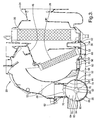
- HVAC unit 20 with a mixing valve sub-assembly 22 is shown in Figure 2.
- the HVAC unit 20 comprises a housing 24, an evaporator 26, a heater core 28, a zone valve 30 and a mixing valve sub-assembly 22.
- the housing 24 defines a primary inlet 32, a first zone outlet 34, a second zone outlet 36 for conveying air between the primary inlet 32 and the first and second zone outlets 34, 36.
- the evaporator 26 is supported by the housing 24 and is disposed downstream of the primary inlet 32.
- the evaporator 26 cools the air entering from a primary inlet 32, one of the primary inlets 32 conveying outside air and the other conveying inside air.
- a cold bias outlet 38 is defined by the housing 24 downstream of the evaporator 26 for bleeding cool air from the evaporator 26.
- the heater core 28 is supported by the housing 24 and is disposed downstream of the evaporator 26. The heater core 28 heats the cool air being delivered from the evaporator 26.
- a hot bias outlet 40 is defined by the housing 24 downstream of the heater core 28 for bleeding hot air from the heater core 28.
- the housing 24 defines a mixing chamber 42 and a cool air path 44.
- the cool air path 44 conveys the cool air from the evaporator 26 to the mixing chamber 42.
- the housing 24 defines a heated air path 46 parallel to the cool air path 44.
- the heated air path 46 conveys air from the heater core 28 to the mixing chamber 42.
- the mixing chamber 42 receives and mixes cool air from the evaporator 26 and hot air from the heater core 28.
- a temperature valve 48 is disposed between the heated air path 46 and the cool air path 44 for apportioning the flow of cool air originating in the evaporator 26 between the cool air path 44 (for airflow into the mixing chamber 42 and the heated air path 46 (for airflow through the heater core 28 then into the mixing chamber 42.
- the zone valve 30 is disposed downstream of the heater core 28 and between the first zone outlet 34 and the second zone outlet 36. The zone valve 30 apportions airflow from the mixing chamber 42 between the first zone outlet 34 and the second zone outlet 36.
- the first zone outlet 34 directs its stream of air to a first vehicle zone
- the second zone outlet 36 directs its stream of air to the mixing valve sub-assembly 22.
- the mixing valve sub-assembly 22 is independent of and mechanically attached to the HVAC housing 24.
- the mixing valve sub-assembly 22 receives and mixes air from the cold bias outlet 38, the hot bias outlet 40, and the second zone outlet 36 and produces at least one additional stream of mixed air having a predetermined temperature independent of the air exiting the first zone outlet 34.
- the mixing valve sub-assembly 22 then delivers the mixed air to the appropriate vehicle zone or zones.
- Each vehicle zone represents a separate area of the vehicle that will receive a distinct temperature-controlled stream of air.
- the first zone outlet 34 may deliver its stream of air to the front driver's area of the cabin, while the stream of air from the mixing valve sub-assembly 22 would be delivered to the front passenger's area of the cabin.
- each zone receives a separate and distinct stream of air controlled by the person occupying the respective zone.
- the mixing valve sub-assembly 22 may be selected from a plurality of mixing valve sub-assemblies 22 each having a different configuration for delivering different numbers of streams of mixed air.
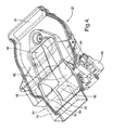
- the embodiment shown in Figure 4 is a mixing valve sub-assembly 22 that yields a single mixed stream.
- the embodiment shown in Figure 5 is a mixing valve sub-assembly 22 that yields two separate mixed streams each having independent temperatures.
- additional mixing valve sub-assemblies 22 could be utilized that would produce more than two mixed streams all having independent temperatures. In each case, the stream or streams exiting the mixing valve sub-assembly 22 will be independent of the stream exiting the first zone outlet 34.
- the mixing valve sub-assembly 22 comprises a casing 50 and a mechanism 52 for mechanical attachment to the housing 24 of the HVAC.
- the casing 50 defines a cold bias inlet 54, a hot bias inlet 56, a second zone inlet 58 and a proportioning chamber 60 having a cylindrical wall 62 and two circular end walls 64.
- the mechanism 52 is used to mechanically attach the casing 50 to the housing 24 of the HVAC with the cold bias inlet 54 in sealing engagement with the cold bias outlet 38, the hot bias inlet 56 in sealing engagement with the hot bias outlet 40 and the second zone inlet 58 in sealing engagement with the second zone outlet 36.
- the cold bias outlet 38, hot bias outlet 40 and second zone outlet 36 of the HVAC housing 24 are connected to the cold bias inlet 54, hot bias inlet 56 and second zone inlet 58 of the sub-assembly casing 50.
- the mechanism 52 for mechanical attachment may comprise various snap-together elements or fasteners.
- the mixing valve sub-assembly 22 may include ramps that snap into slots in the HVAC housing 24 and vice versa.
- the casing 50 also defines a cold bias conduit 66 for conveying air from the cold bias inlet 54 to the proportioning chamber 60, a hot bias conduit 68 for conveying air from the hot bias inlet 56 to the proportioning chamber 60 and a second zone conduit 70 for conveying air from the second zone inlet 58 to the proportioning chamber 60.
- the hot bias conduit 68 leads from the hot bias inlet 56 and terminates in a hot bias aperture 72 in the cylindrical wall 62 of the proportioning chamber 60.
- the cold bias conduit 66 is forked to extend around the hot bias conduit 68.
- the cold bias conduit 66 terminates in two cold bias apertures 74 each in one of the circular end walls 64 of the proportioning chamber 60.
- the second zone conduit 70 leads from the second zone outlet 36 and terminates in a second zone aperture 76 in the cylindrical wall 62 of the proportioning chamber 60.
- the cold bias aperture 74, hot bias aperture 72 and second zone aperture 76 allow the air being conveyed by their respective conduits 66, 68, 70 to enter the proportioning chamber 60.
- the casing 50 also defines a third zone aperture 78 in the cylindrical wall 62 for directing mixed air out of the casing 50.
- the hot bias aperture 72 is substantially diametrically opposite to the third zone aperture 78.
- the hot bias aperture 72 and third zone aperture 78 are, for the most part, diametrically across the cylindrical proportioning chamber 60 from each other.
- the second zone aperture 76 is disposed substantially at a right angle to the diametrically opposite hot bias aperture 72 and third zone aperture 78.
- the second zone aperture 76 is disposed in the top of the proportioning chamber 60 while the hot bias aperture 72 and the third zone aperture 78 are disposed on the sides of the proportioning chamber 60.
- the proportioning chamber 60 is disposed downstream of the cold bias inlet 54, the hot bias inlet 56, and the second zone inlet 58.
- the proportioning chamber 60 receives and mixes air from the cold bias inlet 54, the hot bias inlet 56, and the second zone inlet 58 and produces at a stream of mixed air having a predetermined temperature independent of the air exiting the first zone outlet 34 of the HVAC housing 24.
- the proportioning chamber 60 includes a mixing valve 80 disposed therein to facilitate mixing.
- the mixing valve 80 comprises a hub 82, a sector plate 84, a first curved plate 86 and a second curved plate 88.
- the hub 82 is rotatably and centrally supported on each of the circular end walls 64 of the proportioning chamber 60.
- the hub 82 extends along the line between the centers of the circular end walls 64 and rotates around that same line.
- the sector plate 84 is adjacent each circular end wall 64 and extends between radial edges from the hub 82 to a circular outer periphery extending between the radial edges.
- the sector plate 84 is pie-shaped. The sector plate 84 rotates between a closed position, which covers the respective cold bias apertures 74, and an open position, which fully opens the respective cold bias apertures 74.
- the first curved plate 86 is concentric with the cylindrical wall 62 and extends circumferentially from one of the radial edges of the sector plates 84 for controlling flow through the hot bias aperture 72 .
- the second curved plate 88 is also concentric with the cylindrical wall 62.
- the second curved plate 88 extends circumferentially along the outer peripheries of the sector plates 84 for controlling flow out of the third zone aperture 78.
- the mixing valve sub-assembly 22 also includes an actuator 90 connected to the hub 82.
- the actuator 90 rotates the hub 82, the sector plate 84, the first curved plate 86 and the second curved plate 88 for controlling flow of the air streams into and out of the proportioning chamber 60.
- the casing 50 of the mixing valve sub-assembly 22 can also define a second proportioning chamber 60 in addition to the first with a second mixing valve 80 therein as shown in the embodiment of Figure 5.
- the second proportioning chamber 60 would produce a second stream of mixed air having a second predetermined temperature independent of the air exiting the first proportioning chamber 60 and independent of the air exiting the first zone outlet 34 of the HVAC housing 24.
- the casing 50 of the mixing valve sub-assembly 22 can define more than two proportioning chambers 60 each producing its own stream of air having a separate predetermined temperature.
- the additional proportioning chambers 60 would be fed by a cold bias inlet 54, hot bias inlet 56 and second zone inlet 58 and the respective conduits 66, 68, 70 in a manner similar to the embodiment utilizing a single proportioning chamber 60.
- the invention also includes a method of fabricating an HVAC unit 20 having a housing 24 that defines an air path from a primary inlet 32 to a first zone outlet 34 and a second zone outlet 36, and supporting an evaporator 26 for cooling air, a heater core 28 for heating air and at least one temperature valve 48 for controlling the flow of air through the heater core 28.
- the first step is the selection the mixing valve sub-assembly 22 from a plurality of mixing valve sub-assembly 22 configurations. Each configuration is to be used for receiving and mixing air from the cold bias outlet 38 and from the hot bias outlet 40 and from the second zone outlet 36, all of the HVAC housing 24, to deliver at least one stream of mixed air having a predetermined temperature independent of the temperature of the air exiting the first zone outlet 34 of the HVAC housing 24.
- the selection step is further defined as selecting a mixing valve sub-assembly 22 having a single proportioning chamber 60 for delivering a stream of mixed air having a predetermined temperature independent of the temperature of the air exiting the first zone outlet 34 of the HVAC housing 24.
- the selection step is further defined as selecting a mixing valve sub-assembly 22 having a plurality of proportioning chambers 60 for delivering a plurality of streams of mixed air each having a predetermined temperature independent of the temperature of the air exiting the first zone outlet 34 of the HVAC housing 24 and each having a predetermined temperature independent of each other.
- a universal HVAC module may be supplemented with any one of various mixing valve sub-assemblies 22, each providing a different number of temperature-controlled streams of mixed air having independent temperatures.
- the second step is the attachment of the mixing valve sub-assembly 22 to the housing 24 of the HVAC so that the cold bias inlet 54 of the sub-assembly is in sealing engagement with the cold bias outlet 38 of the HVAC housing 24, the hot bias inlet 56 of the sub-assembly is in sealing engagement with the hot bias outlet 40 of the HVAC housing 24, and the second zone inlet 58 of the mixing valve sub-assembly 22 is in sealing engagement with the second zone outlet 36 of the HVAC housing 24.
- the cold bias outlet 38, hot bias outlet 40 and second zone outlet 36 of the HVAC housing 24 are connected to the cold bias inlet 54, hot bias inlet 56 and second zone inlet 58 of the sub-assembly casing 50.
Landscapes
- Physics & Mathematics (AREA)
- Thermal Sciences (AREA)
- Engineering & Computer Science (AREA)
- Mechanical Engineering (AREA)
- Air-Conditioning For Vehicles (AREA)
- Catching Or Destruction (AREA)
Applications Claiming Priority (2)
| Application Number | Priority Date | Filing Date | Title |
|---|---|---|---|
| US74824205P | 2005-12-07 | 2005-12-07 | |
| US11/604,671 US7832464B2 (en) | 2005-12-07 | 2006-11-27 | Flexible HVAC module with add-on multi-zone sub-assembly |
Publications (3)
| Publication Number | Publication Date |
|---|---|
| EP1795387A2 true EP1795387A2 (de) | 2007-06-13 |
| EP1795387A3 EP1795387A3 (de) | 2008-11-19 |
| EP1795387B1 EP1795387B1 (de) | 2010-10-06 |
Family
ID=37813811
Family Applications (1)
| Application Number | Title | Priority Date | Filing Date |
|---|---|---|---|
| EP06077135A Not-in-force EP1795387B1 (de) | 2005-12-07 | 2006-11-30 | Flexibles Heizungs-, Lüftungs- und Klimatisierungsmodul mit zusätzlicher Mehrzonenbaugruppe |
Country Status (5)
| Country | Link |
|---|---|
| US (1) | US7832464B2 (de) |
| EP (1) | EP1795387B1 (de) |
| KR (1) | KR100830622B1 (de) |
| AT (1) | ATE483595T1 (de) |
| DE (1) | DE602006017322D1 (de) |
Cited By (4)
| Publication number | Priority date | Publication date | Assignee | Title |
|---|---|---|---|---|
| CN103528282A (zh) * | 2013-11-06 | 2014-01-22 | 重庆龙润汽车转向器有限公司 | 用于汽车空调器的前蒸总成 |
| CN103557637A (zh) * | 2013-11-06 | 2014-02-05 | 重庆龙润汽车转向器有限公司 | 适用汽车的空调前蒸器总成 |
| CN106314079A (zh) * | 2016-09-30 | 2017-01-11 | 芜湖豫新世通汽车空调有限公司 | Hvac总成 |
| WO2020246747A1 (en) * | 2019-06-07 | 2020-12-10 | Hanon Systems | Offset tri-zone sliding temperature door strategy |
Families Citing this family (26)
| Publication number | Priority date | Publication date | Assignee | Title |
|---|---|---|---|---|
| US8382563B2 (en) * | 2007-11-08 | 2013-02-26 | Visteon Global Technologies, Inc. | Multi-zone control module for a heating, ventilation, and air conditioning system |
| US7954540B2 (en) * | 2008-12-18 | 2011-06-07 | Delphi Technologies, Inc. | HVAC assembly including temperature mixing valve |
| US9168810B2 (en) * | 2012-10-09 | 2015-10-27 | Delphi Technologies, Inc. | Heating and cooling system for occupants of the rear portion of a vehicle |
| EP2969613B1 (de) * | 2013-03-13 | 2018-08-08 | Bergstrom, Inc. | Klimaanlage mit wärmerückgewinnungslüftung für frischluftzufuhr und temperatursteuerung |
| CN105873778A (zh) | 2013-11-04 | 2016-08-17 | 博格思众公司 | 低轮廓空调系统 |
| CN103557639B (zh) * | 2013-11-06 | 2016-08-24 | 重庆龙润汽车转向器有限公司 | 防止连接风道提前报废的车用空调前蒸总成 |
| US10286748B2 (en) | 2014-05-20 | 2019-05-14 | Mahle International Gmbh | Un-partitioned HVAC module control for multi-zone and high performance operation |
| US9776471B2 (en) | 2014-05-20 | 2017-10-03 | Mahle International Gmbh | Method of controlling the discharge of temperature-conditioned air |
| US9776470B2 (en) | 2014-05-20 | 2017-10-03 | Mahle International Gmbh | Un-partitioned HVAC module control for multi-zone and high performance operation |
| US9783024B2 (en) | 2015-03-09 | 2017-10-10 | Bergstrom Inc. | System and method for remotely managing climate control systems of a fleet of vehicles |
| US9724978B2 (en) | 2015-04-14 | 2017-08-08 | Mahle International Gmbh | HVAC module having an open architecture |
| US9879870B2 (en) | 2015-04-14 | 2018-01-30 | Mahle International Gmbh | HVAC module with anti-backflow control and method of operation |
| US9874384B2 (en) | 2016-01-13 | 2018-01-23 | Bergstrom, Inc. | Refrigeration system with superheating, sub-cooling and refrigerant charge level control |
| US10589598B2 (en) | 2016-03-09 | 2020-03-17 | Bergstrom, Inc. | Integrated condenser and compressor system |
| KR101822287B1 (ko) * | 2016-07-04 | 2018-01-26 | 현대자동차주식회사 | 차량용 공조시스템 |
| US12420616B2 (en) | 2016-08-22 | 2025-09-23 | Bergstrom, Inc. | Multi-compressor oil migration mitigation climate system |
| US10081226B2 (en) | 2016-08-22 | 2018-09-25 | Bergstrom Inc. | Parallel compressors climate system |
| US10562372B2 (en) | 2016-09-02 | 2020-02-18 | Bergstrom, Inc. | Systems and methods for starting-up a vehicular air-conditioning system |
| US10675948B2 (en) | 2016-09-29 | 2020-06-09 | Bergstrom, Inc. | Systems and methods for controlling a vehicle HVAC system |
| US10369863B2 (en) | 2016-09-30 | 2019-08-06 | Bergstrom, Inc. | Refrigerant liquid-gas separator with electronics cooling |
| US10724772B2 (en) | 2016-09-30 | 2020-07-28 | Bergstrom, Inc. | Refrigerant liquid-gas separator having an integrated check valve |
| US11448441B2 (en) | 2017-07-27 | 2022-09-20 | Bergstrom, Inc. | Refrigerant system for cooling electronics |
| US11420496B2 (en) | 2018-04-02 | 2022-08-23 | Bergstrom, Inc. | Integrated vehicular system for conditioning air and heating water |
| US11505032B2 (en) | 2019-07-05 | 2022-11-22 | Hanon Systems | Modular architecture HVAC for multi-zone applications |
| USD1073892S1 (en) | 2021-01-26 | 2025-05-06 | Dometic Sweden Ab | Air conditioning housing |
| EP4281300A1 (de) | 2021-01-26 | 2023-11-29 | Dometic Sweden AB | Fahrzeugklimaanlage |
Citations (1)
| Publication number | Priority date | Publication date | Assignee | Title |
|---|---|---|---|---|
| US6772833B2 (en) | 2002-07-23 | 2004-08-10 | Visteon Global Technologies, Inc. | HVAC system with modular inserts |
Family Cites Families (19)
| Publication number | Priority date | Publication date | Assignee | Title |
|---|---|---|---|---|
| US5062352A (en) * | 1990-07-16 | 1991-11-05 | General Motors Corporation | Motor vehicle heating, ventilating and air conditioning system with combined mode/temperature door |
| US5101883A (en) | 1991-06-27 | 1992-04-07 | General Motors Corporation | Method of assembly of single and multi-zone vehicle heating and a/c systems |
| US5934361A (en) * | 1998-02-27 | 1999-08-10 | General Motors Corporation | Automotive heating and air conditioning assembly with improved air flow and temperature control |
| JP2000062441A (ja) | 1998-08-25 | 2000-02-29 | Denso Corp | 車両用空調装置 |
| EP1090784B1 (de) * | 1999-10-06 | 2005-11-23 | Calsonic Kansei Corporation | Fahrzeugklimaanlage |
| US6223772B1 (en) * | 2000-02-15 | 2001-05-01 | Delphi Technologies, Inc. | Dual function valve assembly |
| WO2001068392A1 (en) * | 2000-03-13 | 2001-09-20 | Zexel Valeo Climate Control Corporation | Air conditioner for car |
| US7096924B2 (en) * | 2000-06-30 | 2006-08-29 | Zexel Valeo Climate Control Corporation | Car air conditioner |
| DE10037384B4 (de) | 2000-08-01 | 2013-04-04 | Behr Gmbh & Co. Kg | Heizungs- und Klimaanlage für ein Kraftfahrzeug |
| US6827141B2 (en) * | 2001-02-23 | 2004-12-07 | International Truck Intellectual Property Company, Llc | Vehicle heating and air conditioning modules |
| KR100723974B1 (ko) | 2001-03-27 | 2007-06-04 | 한라공조주식회사 | 자동차용 공기조화장치 |
| US6547152B1 (en) * | 2001-11-05 | 2003-04-15 | Delphi Technologies, Inc. | Vehicle heating ventilation and air-conditioning module for improved heating and defrosting performance |
| ATE337194T1 (de) * | 2002-06-21 | 2006-09-15 | Behr Gmbh & Co | Modulare heizungs- und/oder klimaanlage für ein kraftfahrzeug |
| US20050124284A1 (en) * | 2003-12-05 | 2005-06-09 | Valeo Climate Control Corp | Airflow control in heating and air conditioning units |
| GB2411227B (en) | 2004-01-28 | 2006-01-18 | Visteon Global Tech Inc | Multiple zoned air conditioning system |
| US7407001B2 (en) * | 2004-09-30 | 2008-08-05 | Valeo Climate Control Corp. | HVAC with detached deflector |
| US7074122B2 (en) * | 2004-11-03 | 2006-07-11 | Visteon Global Technologies, Inc. | Air stream mixing conduit in an air handling module |
| US7654307B2 (en) * | 2006-01-18 | 2010-02-02 | Delphi Technologies, Inc. | Evaporative cooler assisted automotive air conditioning system |
| US7958741B2 (en) * | 2006-04-12 | 2011-06-14 | Delphi Technologies, Inc. | Integrally molded motor isolation system |
-
2006
- 2006-11-27 US US11/604,671 patent/US7832464B2/en not_active Expired - Fee Related
- 2006-11-30 DE DE602006017322T patent/DE602006017322D1/de active Active
- 2006-11-30 EP EP06077135A patent/EP1795387B1/de not_active Not-in-force
- 2006-11-30 AT AT06077135T patent/ATE483595T1/de not_active IP Right Cessation
- 2006-12-07 KR KR1020060123643A patent/KR100830622B1/ko not_active Expired - Fee Related
Patent Citations (1)
| Publication number | Priority date | Publication date | Assignee | Title |
|---|---|---|---|---|
| US6772833B2 (en) | 2002-07-23 | 2004-08-10 | Visteon Global Technologies, Inc. | HVAC system with modular inserts |
Cited By (5)
| Publication number | Priority date | Publication date | Assignee | Title |
|---|---|---|---|---|
| CN103528282A (zh) * | 2013-11-06 | 2014-01-22 | 重庆龙润汽车转向器有限公司 | 用于汽车空调器的前蒸总成 |
| CN103557637A (zh) * | 2013-11-06 | 2014-02-05 | 重庆龙润汽车转向器有限公司 | 适用汽车的空调前蒸器总成 |
| CN103528282B (zh) * | 2013-11-06 | 2015-07-22 | 重庆龙润汽车转向器有限公司 | 用于汽车空调器的前蒸总成 |
| CN106314079A (zh) * | 2016-09-30 | 2017-01-11 | 芜湖豫新世通汽车空调有限公司 | Hvac总成 |
| WO2020246747A1 (en) * | 2019-06-07 | 2020-12-10 | Hanon Systems | Offset tri-zone sliding temperature door strategy |
Also Published As
| Publication number | Publication date |
|---|---|
| US20070144728A1 (en) | 2007-06-28 |
| EP1795387B1 (de) | 2010-10-06 |
| ATE483595T1 (de) | 2010-10-15 |
| KR20070060035A (ko) | 2007-06-12 |
| KR100830622B1 (ko) | 2008-05-21 |
| DE602006017322D1 (de) | 2010-11-18 |
| EP1795387A3 (de) | 2008-11-19 |
| US7832464B2 (en) | 2010-11-16 |
Similar Documents
| Publication | Publication Date | Title |
|---|---|---|
| EP1795387B1 (de) | Flexibles Heizungs-, Lüftungs- und Klimatisierungsmodul mit zusätzlicher Mehrzonenbaugruppe | |
| US5676595A (en) | Air duct selector and automotive air conditioner | |
| US6772833B2 (en) | HVAC system with modular inserts | |
| US8382563B2 (en) | Multi-zone control module for a heating, ventilation, and air conditioning system | |
| CN108025622B (zh) | 机动车辆供暖、通风和/或空调装置和相应的附加模块以及组装方法 | |
| US5101883A (en) | Method of assembly of single and multi-zone vehicle heating and a/c systems | |
| JP2003127636A (ja) | 自動車両のキャビン用に設定温度の空気流を発生する装置、ならびにこの装置を備える暖房機器または空調機器 | |
| JP4550572B2 (ja) | 自動車用モジュラー暖房および/または空調装置 | |
| CN115782504B (zh) | 一种机动车辆的空调装置 | |
| US20060151161A1 (en) | Modular system for a 1-to-4 zone climate control system for vehicles | |
| US11872868B2 (en) | Sliding temperature door architecture for HVAC module | |
| US20080032617A1 (en) | Modular Motor Vehicle Air-Conditioning Unit | |
| US7201220B2 (en) | Air-conditioning unit without air-mix door | |
| KR20180041573A (ko) | 자동차의 온도조절 시스템을 위한 에어 다이버터 | |
| JPH05278448A (ja) | 車両用空調装置 | |
| US20080017366A1 (en) | Air-Conditioning System, Especially Automotive Air-Conditioning System | |
| EP1889738B1 (de) | Luftsteuerungsvorrichtung zur Erwärmung und/oder Klimaanlage für Fahrzeuge | |
| KR102750239B1 (ko) | 다구역 애플리케이션을 위한 모듈식 아키텍쳐 hvac | |
| CN113825658B (zh) | 控制装置和相关的供暖和/或通风和/或空调设备、机动车辆和温度管理方法 | |
| US11524549B2 (en) | Off set tri-zone sliding temperature door strategy | |
| KR102379897B1 (ko) | 차량용 모듈식 공기 조화 시스템 | |
| JP7013983B2 (ja) | 空気吹出装置 | |
| KR102079955B1 (ko) | 세미 센터 마운팅 타입 차량 공조장치 | |
| JP2006123712A (ja) | 車両用空調装置 | |
| KR20090063402A (ko) | 센터 마운팅 타입 차량 공조장치 |
Legal Events
| Date | Code | Title | Description |
|---|---|---|---|
| PUAI | Public reference made under article 153(3) epc to a published international application that has entered the european phase |
Free format text: ORIGINAL CODE: 0009012 |
|
| AK | Designated contracting states |
Kind code of ref document: A2 Designated state(s): AT BE BG CH CY CZ DE DK EE ES FI FR GB GR HU IE IS IT LI LT LU LV MC NL PL PT RO SE SI SK TR |
|
| AX | Request for extension of the european patent |
Extension state: AL BA HR MK YU |
|
| PUAL | Search report despatched |
Free format text: ORIGINAL CODE: 0009013 |
|
| AK | Designated contracting states |
Kind code of ref document: A3 Designated state(s): AT BE BG CH CY CZ DE DK EE ES FI FR GB GR HU IE IS IT LI LT LU LV MC NL PL PT RO SE SI SK TR |
|
| AX | Request for extension of the european patent |
Extension state: AL BA HR MK RS |
|
| 17P | Request for examination filed |
Effective date: 20090519 |
|
| AKX | Designation fees paid |
Designated state(s): AT BE BG CH CY CZ DE DK EE ES FI FR GB GR HU IE IS IT LI LT LU LV MC NL PL PT RO SE SI SK TR |
|
| 17Q | First examination report despatched |
Effective date: 20090626 |
|
| GRAP | Despatch of communication of intention to grant a patent |
Free format text: ORIGINAL CODE: EPIDOSNIGR1 |
|
| GRAS | Grant fee paid |
Free format text: ORIGINAL CODE: EPIDOSNIGR3 |
|
| GRAA | (expected) grant |
Free format text: ORIGINAL CODE: 0009210 |
|
| AK | Designated contracting states |
Kind code of ref document: B1 Designated state(s): AT BE BG CH CY CZ DE DK EE ES FI FR GB GR HU IE IS IT LI LT LU LV MC NL PL PT RO SE SI SK TR |
|
| REG | Reference to a national code |
Ref country code: GB Ref legal event code: FG4D |
|
| REG | Reference to a national code |
Ref country code: CH Ref legal event code: EP |
|
| REG | Reference to a national code |
Ref country code: IE Ref legal event code: FG4D |
|
| REF | Corresponds to: |
Ref document number: 602006017322 Country of ref document: DE Date of ref document: 20101118 Kind code of ref document: P |
|
| REG | Reference to a national code |
Ref country code: NL Ref legal event code: VDEP Effective date: 20101006 |
|
| PG25 | Lapsed in a contracting state [announced via postgrant information from national office to epo] |
Ref country code: SI Free format text: LAPSE BECAUSE OF FAILURE TO SUBMIT A TRANSLATION OF THE DESCRIPTION OR TO PAY THE FEE WITHIN THE PRESCRIBED TIME-LIMIT Effective date: 20101006 |
|
| LTIE | Lt: invalidation of european patent or patent extension |
Effective date: 20101006 |
|
| PG25 | Lapsed in a contracting state [announced via postgrant information from national office to epo] |
Ref country code: LT Free format text: LAPSE BECAUSE OF FAILURE TO SUBMIT A TRANSLATION OF THE DESCRIPTION OR TO PAY THE FEE WITHIN THE PRESCRIBED TIME-LIMIT Effective date: 20101006 |
|
| PG25 | Lapsed in a contracting state [announced via postgrant information from national office to epo] |
Ref country code: LV Free format text: LAPSE BECAUSE OF FAILURE TO SUBMIT A TRANSLATION OF THE DESCRIPTION OR TO PAY THE FEE WITHIN THE PRESCRIBED TIME-LIMIT Effective date: 20101006 Ref country code: IS Free format text: LAPSE BECAUSE OF FAILURE TO SUBMIT A TRANSLATION OF THE DESCRIPTION OR TO PAY THE FEE WITHIN THE PRESCRIBED TIME-LIMIT Effective date: 20110206 Ref country code: FI Free format text: LAPSE BECAUSE OF FAILURE TO SUBMIT A TRANSLATION OF THE DESCRIPTION OR TO PAY THE FEE WITHIN THE PRESCRIBED TIME-LIMIT Effective date: 20101006 Ref country code: NL Free format text: LAPSE BECAUSE OF FAILURE TO SUBMIT A TRANSLATION OF THE DESCRIPTION OR TO PAY THE FEE WITHIN THE PRESCRIBED TIME-LIMIT Effective date: 20101006 Ref country code: BG Free format text: LAPSE BECAUSE OF FAILURE TO SUBMIT A TRANSLATION OF THE DESCRIPTION OR TO PAY THE FEE WITHIN THE PRESCRIBED TIME-LIMIT Effective date: 20110106 Ref country code: SE Free format text: LAPSE BECAUSE OF FAILURE TO SUBMIT A TRANSLATION OF THE DESCRIPTION OR TO PAY THE FEE WITHIN THE PRESCRIBED TIME-LIMIT Effective date: 20101006 Ref country code: AT Free format text: LAPSE BECAUSE OF FAILURE TO SUBMIT A TRANSLATION OF THE DESCRIPTION OR TO PAY THE FEE WITHIN THE PRESCRIBED TIME-LIMIT Effective date: 20101006 Ref country code: PT Free format text: LAPSE BECAUSE OF FAILURE TO SUBMIT A TRANSLATION OF THE DESCRIPTION OR TO PAY THE FEE WITHIN THE PRESCRIBED TIME-LIMIT Effective date: 20110207 |
|
| PG25 | Lapsed in a contracting state [announced via postgrant information from national office to epo] |
Ref country code: GR Free format text: LAPSE BECAUSE OF FAILURE TO SUBMIT A TRANSLATION OF THE DESCRIPTION OR TO PAY THE FEE WITHIN THE PRESCRIBED TIME-LIMIT Effective date: 20110107 Ref country code: BE Free format text: LAPSE BECAUSE OF FAILURE TO SUBMIT A TRANSLATION OF THE DESCRIPTION OR TO PAY THE FEE WITHIN THE PRESCRIBED TIME-LIMIT Effective date: 20101006 Ref country code: MC Free format text: LAPSE BECAUSE OF NON-PAYMENT OF DUE FEES Effective date: 20101130 |
|
| REG | Reference to a national code |
Ref country code: CH Ref legal event code: PL |
|
| PG25 | Lapsed in a contracting state [announced via postgrant information from national office to epo] |
Ref country code: EE Free format text: LAPSE BECAUSE OF FAILURE TO SUBMIT A TRANSLATION OF THE DESCRIPTION OR TO PAY THE FEE WITHIN THE PRESCRIBED TIME-LIMIT Effective date: 20101006 Ref country code: CZ Free format text: LAPSE BECAUSE OF FAILURE TO SUBMIT A TRANSLATION OF THE DESCRIPTION OR TO PAY THE FEE WITHIN THE PRESCRIBED TIME-LIMIT Effective date: 20101006 Ref country code: ES Free format text: LAPSE BECAUSE OF FAILURE TO SUBMIT A TRANSLATION OF THE DESCRIPTION OR TO PAY THE FEE WITHIN THE PRESCRIBED TIME-LIMIT Effective date: 20110117 Ref country code: CH Free format text: LAPSE BECAUSE OF NON-PAYMENT OF DUE FEES Effective date: 20101130 Ref country code: LI Free format text: LAPSE BECAUSE OF NON-PAYMENT OF DUE FEES Effective date: 20101130 |
|
| PLBE | No opposition filed within time limit |
Free format text: ORIGINAL CODE: 0009261 |
|
| STAA | Information on the status of an ep patent application or granted ep patent |
Free format text: STATUS: NO OPPOSITION FILED WITHIN TIME LIMIT |
|
| PG25 | Lapsed in a contracting state [announced via postgrant information from national office to epo] |
Ref country code: PL Free format text: LAPSE BECAUSE OF FAILURE TO SUBMIT A TRANSLATION OF THE DESCRIPTION OR TO PAY THE FEE WITHIN THE PRESCRIBED TIME-LIMIT Effective date: 20101006 Ref country code: DK Free format text: LAPSE BECAUSE OF FAILURE TO SUBMIT A TRANSLATION OF THE DESCRIPTION OR TO PAY THE FEE WITHIN THE PRESCRIBED TIME-LIMIT Effective date: 20101006 Ref country code: SK Free format text: LAPSE BECAUSE OF FAILURE TO SUBMIT A TRANSLATION OF THE DESCRIPTION OR TO PAY THE FEE WITHIN THE PRESCRIBED TIME-LIMIT Effective date: 20101006 Ref country code: RO Free format text: LAPSE BECAUSE OF FAILURE TO SUBMIT A TRANSLATION OF THE DESCRIPTION OR TO PAY THE FEE WITHIN THE PRESCRIBED TIME-LIMIT Effective date: 20101006 |
|
| 26N | No opposition filed |
Effective date: 20110707 |
|
| GBPC | Gb: european patent ceased through non-payment of renewal fee |
Effective date: 20110106 |
|
| PG25 | Lapsed in a contracting state [announced via postgrant information from national office to epo] |
Ref country code: IE Free format text: LAPSE BECAUSE OF NON-PAYMENT OF DUE FEES Effective date: 20101130 |
|
| REG | Reference to a national code |
Ref country code: DE Ref legal event code: R097 Ref document number: 602006017322 Country of ref document: DE Effective date: 20110707 |
|
| PG25 | Lapsed in a contracting state [announced via postgrant information from national office to epo] |
Ref country code: GB Free format text: LAPSE BECAUSE OF NON-PAYMENT OF DUE FEES Effective date: 20110106 |
|
| PG25 | Lapsed in a contracting state [announced via postgrant information from national office to epo] |
Ref country code: CY Free format text: LAPSE BECAUSE OF FAILURE TO SUBMIT A TRANSLATION OF THE DESCRIPTION OR TO PAY THE FEE WITHIN THE PRESCRIBED TIME-LIMIT Effective date: 20101006 |
|
| PG25 | Lapsed in a contracting state [announced via postgrant information from national office to epo] |
Ref country code: LU Free format text: LAPSE BECAUSE OF NON-PAYMENT OF DUE FEES Effective date: 20101130 Ref country code: HU Free format text: LAPSE BECAUSE OF FAILURE TO SUBMIT A TRANSLATION OF THE DESCRIPTION OR TO PAY THE FEE WITHIN THE PRESCRIBED TIME-LIMIT Effective date: 20110407 |
|
| PG25 | Lapsed in a contracting state [announced via postgrant information from national office to epo] |
Ref country code: TR Free format text: LAPSE BECAUSE OF FAILURE TO SUBMIT A TRANSLATION OF THE DESCRIPTION OR TO PAY THE FEE WITHIN THE PRESCRIBED TIME-LIMIT Effective date: 20101006 |
|
| REG | Reference to a national code |
Ref country code: DE Ref legal event code: R082 Ref document number: 602006017322 Country of ref document: DE Representative=s name: BRP RENAUD UND PARTNER MBB, DE Ref country code: DE Ref legal event code: R081 Ref document number: 602006017322 Country of ref document: DE Owner name: MAHLE INTERNATIONAL GMBH, DE Free format text: FORMER OWNER: DELPHI TECHNOLOGIES, INC., TROY, MICH., US Ref country code: DE Ref legal event code: R082 Ref document number: 602006017322 Country of ref document: DE Representative=s name: BRP RENAUD UND PARTNER MBB RECHTSANWAELTE PATE, DE |
|
| REG | Reference to a national code |
Ref country code: FR Ref legal event code: PLFP Year of fee payment: 10 |
|
| REG | Reference to a national code |
Ref country code: FR Ref legal event code: PLFP Year of fee payment: 11 |
|
| REG | Reference to a national code |
Ref country code: FR Ref legal event code: PLFP Year of fee payment: 12 |
|
| REG | Reference to a national code |
Ref country code: FR Ref legal event code: TP Owner name: MAHLE INTERNATIONAL GMBH, DE Effective date: 20180103 |
|
| PGFP | Annual fee paid to national office [announced via postgrant information from national office to epo] |
Ref country code: IT Payment date: 20191122 Year of fee payment: 14 Ref country code: FR Payment date: 20191127 Year of fee payment: 14 |
|
| PGFP | Annual fee paid to national office [announced via postgrant information from national office to epo] |
Ref country code: DE Payment date: 20200130 Year of fee payment: 14 |
|
| REG | Reference to a national code |
Ref country code: DE Ref legal event code: R119 Ref document number: 602006017322 Country of ref document: DE |
|
| PG25 | Lapsed in a contracting state [announced via postgrant information from national office to epo] |
Ref country code: FR Free format text: LAPSE BECAUSE OF NON-PAYMENT OF DUE FEES Effective date: 20201130 Ref country code: IT Free format text: LAPSE BECAUSE OF NON-PAYMENT OF DUE FEES Effective date: 20201130 |
|
| PG25 | Lapsed in a contracting state [announced via postgrant information from national office to epo] |
Ref country code: DE Free format text: LAPSE BECAUSE OF NON-PAYMENT OF DUE FEES Effective date: 20210601 |