EP1795281A2 - Kokille - Google Patents
Kokille Download PDFInfo
- Publication number
- EP1795281A2 EP1795281A2 EP06023083A EP06023083A EP1795281A2 EP 1795281 A2 EP1795281 A2 EP 1795281A2 EP 06023083 A EP06023083 A EP 06023083A EP 06023083 A EP06023083 A EP 06023083A EP 1795281 A2 EP1795281 A2 EP 1795281A2
- Authority
- EP
- European Patent Office
- Prior art keywords
- water
- mold
- mold tube
- cooling
- gap
- Prior art date
- Legal status (The legal status is an assumption and is not a legal conclusion. Google has not performed a legal analysis and makes no representation as to the accuracy of the status listed.)
- Granted
Links
Images
Classifications
-
- B—PERFORMING OPERATIONS; TRANSPORTING
- B22—CASTING; POWDER METALLURGY
- B22D—CASTING OF METALS; CASTING OF OTHER SUBSTANCES BY THE SAME PROCESSES OR DEVICES
- B22D11/00—Continuous casting of metals, i.e. casting in indefinite lengths
- B22D11/04—Continuous casting of metals, i.e. casting in indefinite lengths into open-ended moulds
- B22D11/055—Cooling the moulds
Definitions
- the invention relates to a mold for the continuous casting of metal with the features of the preamble of claim 1.
- Tubular molds of copper or copper alloys for casting profiles of steel and other high melting point metals have been widely described in the art.
- the mold tubes are cooled by cooling water, which flows through a water gap between the inside of the wall of a surrounding the mold tube water box and the outside of the mold tube.
- the mold tube is oriented by way of adjusting screws in the water box so that adjusts the desired width of the water gap on the circumferential side of the mold tube. Since the mold tube is subject to extreme thermal stresses, the exact alignment of the mold tube in the water box must be done very carefully so that it does not come due to different widths of the water gap at different flow velocities and thus to a different degree of heat dissipation. This would result in a different strand shell growth and different degrees of shrinkage. This in turn can lead to material tensions and cracks in the strand shell, which increases the risk of strand penetration.
- the invention has the object to show a liquid-cooled mold for continuous casting of metal, in which the complex orientation of the mold is simplified within the water box.
- the solution is seen in a mold with the features of claim 1.
- Advantageous embodiments of the inventive concept are the subject of the dependent claims.
- the mold according to the invention it is provided that at least one water baffle is arranged in the water gap.
- the water guide plate leads to cross-sectional changes of the water gap, the cross-sectional changes resulting in a change in the flow velocity. Since the mold tube is mounted freely displaceable relative to the water tank at least in one direction, the working position of the mold tube can be adjusted by the flow conditions in the water gap itself. As a result, the mold tube is self-centering in the water box orientation. Self-centering is achieved by balancing the hydrodynamic forces in the water gap. If, for example, the width of the water gap on one side of the mold tube becomes greater, the flow velocity drops in this area. The hydrodynamic force acting on the outer wall of the mold tube also decreases in this area.
- the water guide plate is arranged in the region of the cooling grooves.
- the flow cross section in the area of the cooling grooves increases, which leads to a reduction in the flow velocity.
- the water guide plate at least partially reduces the flow cross section in the region of the cooling grooves.
- the water baffle has an end-side bypass section, which is designed such that cooling water is directed from the water gap targeted into the cooling grooves.
- the bypass section is configured in a streamlined manner, so that as far as possible no turbulence forms in the coolant gap.
- the diverting section is configured arcuate.
- the flow velocity in the inflow and outflow region of the cooling grooves is increased by the water guide plate.
- the local increases in the flow velocities also lead to an increase in the hydrodynamic forces in this area. It is favorable if the regions of increased flow velocity are arranged diametrically at the same height of the mold tube. Preferably, therefore, all Wasserleitbleche are configured identically.
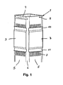
- Figure 1 shows a mold tube 1 rectangular cross-section, which is placed in a water tank, not shown.
- the mold tube 1 is liquid-cooled from the outside, wherein between the inside of the wall of the channel box and the outside 2 of the mold tube 1, a water gap is formed.
- the Wasserleitbleche 3 shown are arranged.
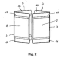
- the Wasserleitbleche 3 are clearly visible in their spatial arrangement in the perspective view of Figure 2.
- four Wasserleitbleche 3 are provided, with always two Wasserleitbleche 3 are opposite to the same height.
- the water guide plates 3 are identically configured and extend almost over the entire width of a side wall 5 of the mold tube 1, wherein the corner regions 6 are recessed.
- a partial region of the outer sides 2 of the mold tube is provided with a cooling groove 7 extending in the flow direction.
- the cooling grooves 7 do not extend over the entire length of the mold tube 1, but only in the region of the G fauxLitesolllage, since the largest heat flux densities occur and a correspondingly intensive cooling of the mold tube 1 is required.
- the cooling grooves 7 lead to an enlargement of the cooling surface, so that the heat transfer is facilitated in the cooling water.
- the water guide plates 3 are placed in the region of the cooling grooves 7, wherein the water guide plates 3 are somewhat shorter than the cooling grooves 7. That is, the cooling grooves 7 protrude below the water guide plate 3 both in their inflow and outflow regions.
- a guide groove 8 can be seen at the upper end 4 of the mold tube 1, via which the mold tube 1 is held in the vertical direction on the water tank, not shown.
- the guide groove 8 is configured so that a displacement transverse to the flow direction of the cooling water is possible.
- the Wasserleitbleche 3 are rectangularly configured and have a flat central portion 9, which at each end, ie seen in the flow direction Umleitabitese 10, 11 connect.
- the Umleitabitese 10, 11 are issued in the direction of the mold 1 and are configured arcuately.
- the diverting sections 10, 11 are identical, that is trough-shaped.
- the exact contour or the radius of the channel-shaped sections is preferably matched to the depth profile of the cooling grooves 7.
- the cooling grooves 7 preferably have a radius in the inflow and outflow region in order to avoid turbulence in the cooling water flow when entering the cooling grooves 7. This radius can also be used in the curved diverting sections.
Landscapes
- Engineering & Computer Science (AREA)
- Mechanical Engineering (AREA)
- Continuous Casting (AREA)
Abstract
Description
- Die Erfindung betrifft eine Kokille zum Stranggießen von Metall mit den Merkmalen des Oberbegriffs des Patentanspruchs 1.
- Rohrförmige Kokillen aus Kupfer oder Kupferlegierungen zum Gießen von Profilen aus Stahl und anderen Metallen mit hohem Schmelzpunkt sind vielfach im Stand der Technik beschrieben worden. Die Kokillenrohre werden dabei durch Kühlwasser gekühlt, das einen Wasserspalt zwischen der Innenseite der Wandung eines das Kokillenrohr umgebenden Wasserkastens und der Außenseite des Kokillenrohrs durchströmt. Üblicherweise wird das Kokillenrohr über Einstellschrauben derart in dem Wasserkasten lageorientiert, dass sich umfangsseitig des Kokillenrohrs die gewünschte Breite des Wasserspalts einstellt. Da das Kokillenrohr extremen thermischen Belastungen unterliegt, muss die exakte Ausrichtung des Kokillenrohrs im Wasserkasten sehr sorgfältig erfolgen, damit es nicht aufgrund unterschiedlicher Breiten des Wasserspalts zu unterschiedlichen Strömungsgeschwindigkeiten und damit zu einem unterschiedlich starken Wärmeabfluss kommt. Dies hätte ein unterschiedliches Strangschalenwachstum und unterschiedlich starke Schrumpfungen zur Folge. Dies kann wiederum zu Materialspannungen und Rissen in der Strangschale führen, wodurch sich das Risiko eines Strangdurchbruches erhöht.
- Hiervon ausgehend liegt der Erfindung die Aufgabe zugrunde, eine flüssigkeitsgekühlte Kokille zum Stranggießen von Metall aufzuzeigen, bei welcher die aufwendige Ausrichtung der Kokille innerhalb des Wasserkastens vereinfacht wird. Die Lösung wird in einer Kokille mit den Merkmalen des Patentanspruchs 1 gesehen. Vorteilhafte Ausgestaltungen des Erfindungsgedankens sind Gegenstand der Unteransprüche.
- Bei der erfindungsgemäßen Kokille ist vorgesehen, dass in dem Wasserspalt wenigstens ein Wasserleitblech angeordnet ist. Das Wasserleitblech führt zu Querschnittsveränderungen des Wasserspalts, wobei die Querschnittsveränderungen in einer Veränderung der Strömungsgeschwindigkeit resultieren. Da das Kokillenrohr zumindest in eine Richtung frei verschiebbar gegenüber dem Wasserkasten gelagert ist, kann sich die Arbeitslage des Kokillenrohrs durch die Strömungsverhältnisse im Wasserspalt selbst einstellen. Dadurch wird das Kokillenrohr selbstzentrierend in dem Wasserkasten lageorientiert. Die Selbstzentrierung wird dadurch erreicht, dass sich die hydrodynamischen Kräfte im Wasserspalt gegenseitig ausgleichen. Wird die Breite des Wasserspalts auf einer Seite des Kokillenrohrs beispielsweise größer, sinkt in diesem Bereich die Strömungsgeschwindigkeit. Die hydrodynamische Kraft, die auf die Außenwand des Kokillenrohrs wirkt, sinkt in diesem Bereich ebenfalls. Im gleichen Maß führt die Reduzierung der Breite des Wasserspalts auf der gegenüberliegenden Seite des Kokillenrohrs zu einer Erhöhung der Strömungsgeschwindigkeit, wodurch sich in diesem Bereich höhere hydrodynamische Kräfte einstellen, die sich aufgrund des seitlich frei verschiebbaren Kokillenrohrs dahingehend auswirken, dass das Kokillenrohr geringfügig verschoben wird, bis sich wieder ein Kräftegleichgewicht ergibt. Die Wasserleitbleche sind daher in sich jeweils gegenüber liegenden Bereichen des Kokillenrohrs bzw. des Wasserspalts angeordnet.
- Insbesondere wird es als zweckmäßig angesehen, wenn zumindest ein Teilbereich der Außenfläche des Kokillenrohrs mit Kühlnuten versehen ist, wobei das Wasserleitblech im Bereich der Kühlnuten angeordnet ist. Bei einem Wasserspalt konstanten Querschnitts vergrößert sich der Strömungsquerschnitt im Bereich der Kühlnuten, was zu einer Reduzierung der Strömungsgeschwindigkeit führt. Um Kühlwasser mit hoher Geschwindigkeit durch die Kühlnuten zu führen, ist vorgesehen, dass das Wasserleitblech den Strömungsquerschnitt im Bereich der Kühlnuten zumindest bereichsweise verkleinert. Hierfür besitzt das Wasserleitblech einen endseitigen Umleitabschnitt, welcher derart ausgebildet ist, dass Kühlwasser aus dem Wasserspalt gezielt in die Kühlnuten geleitet wird. Der Umleitabschnitt ist strömungsgünstig konfiguriert, so dass sich möglichst keine Verwirbelungen im Kühlmittelspalt bilden. Zweckmäßigerweise ist der Umleitabschnitt bogenförmig konfiguriert.
- Gemäß der Ausführungsform des Patentanspruchs 6 wird die Strömungsgeschwindigkeit im Einström- und Ausströmbereich der Kühlnuten durch das Wasserleitblech erhöht. Die lokalen Erhöhungen der Strömungsgeschwindigkeiten führen auch zu einem Anstieg der hydrodynamischen Kräfte in diesem Bereich. Es ist günstig, wenn die Bereiche erhöhter Strömungsgeschwindigkeit diametral auf gleicher Höhe des Kokillenrohrs angeordnet sind. Vorzugsweise sind daher sämtliche Wasserleitbleche identisch konfiguriert.
- Die Erfindung wird nachfolgend anhand des in den Figuren 1 und 2 schematisch dargestellten Ausführungsbeispiels näher erläutert. Figur 1 zeigt ein Kokillenrohr 1 rechteckigen Querschnitts, das in einem nicht näher dargestellten Wasserkasten platziert wird. Das Kokillenrohr 1 wird von außen flüssigkeitsgekühlt, wobei zwischen der Innenseite der Wandung des Wasserkastens und der Außenseite 2 des Kokillenrohrs 1 ein Wasserspalt ausgebildet wird. In diesem Wasserspalt werden die dargestellten Wasserleitbleche 3 angeordnet.
- Die Wasserleitbleche 3 sind in ihrer räumlichen Anordnung in der perspektivischen Darstellung der Figur 2 gut zu erkennen. Bei diesem Ausführungsbeispiel sind vier Wasserleitbleche 3 vorgesehen, wobei sich immer zwei Wasserleitbleche 3 auf gleicher Höhe gegenüber liegen. Die Wasserleitbleche 3 sind identisch konfiguriert und erstrecken sich nahezu über die gesamte Breite einer Seitenwand 5 des Kokillenrohrs 1, wobei die Eckbereiche 6 ausgespart werden.
- In Figur 1 ist zu erkennen, dass ein Teilbereich der Außenseiten 2 des Kokillenrohrs mit einer sich in Strömungsrichtung erstreckenden Kühlnut 7 versehen ist. Die Kühlnuten 7 erstrecken sich nicht über die gesamte Länge des Kokillenrohrs 1, sondern ausschließlich im Bereich der Gießspiegelsolllage, da hier die größten Wärmestromdichten auftreten und eine entsprechend intensive Kühlung des Kokillenrohrs 1 erforderlich ist. Die Kühlnuten 7 führen zu einer Vergrößerung der Kühlfläche, so dass der Wärmeübergang in das Kühlwasser erleichtert wird. Im Bereich der Kühlnuten 7 sind die Wasserleitbleche 3 platziert, wobei die Wasserleitbleche 3 etwas kürzer sind als die Kühlnuten 7. Das heißt, die Kühlnuten 7 ragen sowohl in ihrem Einström- als auch in ihrem Ausströmbereich unter dem Wasserleitblech 3 hervor. Des weiteren ist in Figur 1 eine Führungsnut 8 am oberen Ende 4 des Kokillenrohrs 1 zu erkennen, über welche das Kokillenrohr 1 in Hochrichtung an dem nicht näher dargestellten Wasserkasten gehalten ist. Die Führungsnut 8 ist so konfiguriert, dass eine Verlagerung quer zur Strömungsrichtung des Kühlwassers möglich ist.
- Die Wasserleitbleche 3 sind rechteckig konfiguriert und besitzen einen ebenen Mittelabschnitt 9, an welchen sich jeweils endseitig, das heißt in Strömungsrichtung gesehen Umleitabschnitte 10, 11 anschließen. Die Umleitabschnitte 10, 11 sind in Richtung zur Kokille 1 ausgestellt und sind dabei bogenförmig konfiguriert. In diesem Ausführungsbeispiel sind die Umleitabschnitte 10, 11 identisch, das heißt rinnenförmig ausgebildet. Die genaue Kontur bzw. der Radius der rinnenförmigen Abschnitte ist bevorzugt auf den Tiefenverlauf der Kühlnuten 7 abgestimmt. Die Kühlnuten 7 besitzen im Ein- und Ausströmbereich vorzugsweise einen Radius, um Verwirbelungen im Kühlwasserstrom beim Eintritt in die Kühlnuten 7 zu vermeiden. Dieser Radius kann auch bei den bogenförmigen Umleitabschnitten verwendet werden.
-
- 1 -
- Kokillenrohr
- 2 -
- Außenseite v. 1
- 3 -
- Wasserleitblech
- 4 -
- oberes Ende v. 1
- 5 -
- Seitenwand
- 6 -
- Eckbereich
- 7 -
- Kühlnut
- 8 -
- Führungsnut
- 9 -
- Mittelabschnitt
- 10 -
- Umleitabschnitt
- 11 -
- Umleitabschnitt
Claims (7)
- Kokille zum Stranggießen von Metall mit einem in einem Wasserkasten platzierten Kokillenrohr (1), wobei zwischen der Inneseite der Wandung des Wasserkastens und der Außenseite (2) des Kokillenrohrs (1) ein Wasserspalt ausgebildet ist, dadurch gekennzeichnet, dass in dem Wasserspalt wenigstens ein Wasserleitblech (3) angeordnet ist, wobei das Kokillenrohr (1) zumindest in eine Richtung seitlich frei verschiebbar gegenüber dem Wasserkasten gelagert ist und wobei sich die Arbeitslage des Kokillenrohrs (1) durch die Strömungsverhältnisse im Wasserspalt einstellt.
- Kokille nach Aspruch 1, dadurch gekennzeichnet, dass das Kokillenrohr (1) selbstzentrierend in dem Wasserkasten lageorientiert ist.
- Kokille nach Anspruch 1 oder 2, dadurch gekennzeichnet, dass zumindest ein Teilbereich der Außenfläche (2) des Kokillenrohrs (1) mit Kühlnuten (7) versehen ist, wobei das Wasserleitblech (3) im Bereich der Kühlnuten (7) angeordnet ist.
- Kokille nach einem der Ansprüche 1 bis 3, dadurch gekennzeichnet, dass das Wasserleitblech (3) einen endseitigen Umleitabsschnitt (10, 11) aufweist, welcher derart ausgebildet ist, dass Kühlwasser aus dem Wasserspalt gezielt in die Kühlnuten (7) geleitet wird.
- Kokille nach Anspruch 4, dadurch gekennzeichnet, dass der Umleitabschnitt (10, 11) bogenförmig konfiguriert ist.
- Kokille nach einem der Ansprüche 3 bis 5, dadurch gekennzeichnet, dass die Strömungsgeschwindigkeit im Einström- und Ausströmbereich der Kühlnuten (7) durch das Wasserleitblech (10, 11) erhöht ist.
- Kokille nach einem der Ansprüche 1 bis 6, dadurch gekennzeichnet, dass Wasserleitbleche (3) in sich gegenüber liegenden Bereichen des Kokillenrohrs (7) angeordnet sind.
Applications Claiming Priority (1)
| Application Number | Priority Date | Filing Date | Title |
|---|---|---|---|
| DE102005059712A DE102005059712A1 (de) | 2005-12-12 | 2005-12-12 | Kokille |
Publications (3)
| Publication Number | Publication Date |
|---|---|
| EP1795281A2 true EP1795281A2 (de) | 2007-06-13 |
| EP1795281A3 EP1795281A3 (de) | 2008-07-09 |
| EP1795281B1 EP1795281B1 (de) | 2012-01-25 |
Family
ID=37909422
Family Applications (1)
| Application Number | Title | Priority Date | Filing Date |
|---|---|---|---|
| EP06023083A Not-in-force EP1795281B1 (de) | 2005-12-12 | 2006-11-07 | Stranggiesskokille |
Country Status (11)
| Country | Link |
|---|---|
| US (1) | US7658221B2 (de) |
| EP (1) | EP1795281B1 (de) |
| JP (1) | JP4722821B2 (de) |
| KR (1) | KR101225806B1 (de) |
| CN (1) | CN101007339B (de) |
| AT (1) | ATE542620T1 (de) |
| BR (1) | BRPI0605210A (de) |
| CA (1) | CA2570957C (de) |
| DE (1) | DE102005059712A1 (de) |
| ES (1) | ES2381388T3 (de) |
| RU (1) | RU2404014C2 (de) |
Cited By (2)
| Publication number | Priority date | Publication date | Assignee | Title |
|---|---|---|---|---|
| ITUD20110211A1 (it) * | 2011-12-23 | 2013-06-24 | Danieli Off Mecc | Cristallizzatore per colata continua |
| ITUD20130090A1 (it) * | 2013-06-28 | 2014-12-29 | Danieli Off Mecc | Cristallizzatore per colata continua e procedimento per la sua realizzazione |
Families Citing this family (3)
| Publication number | Priority date | Publication date | Assignee | Title |
|---|---|---|---|---|
| CA2854210C (en) * | 2011-11-04 | 2015-02-10 | Hatch Ltd. | Cooling of chill molds using baffles |
| AT512433B1 (de) * | 2012-01-30 | 2017-08-15 | Primetals Technologies Austria GmbH | Durchlaufkokille zum stranggiessen eines strangs mit knüppel- oder vorblockprofil |
| DE102023115151B3 (de) | 2023-04-28 | 2024-08-01 | Cunova Gmbh | Kokillenkörper |
Citations (2)
| Publication number | Priority date | Publication date | Assignee | Title |
|---|---|---|---|---|
| DE19716450A1 (de) | 1996-05-13 | 1998-05-28 | Km Europa Metal Ag | Flüssigkeitsgekühlte Kokille |
| EP1398099A1 (de) | 2002-08-16 | 2004-03-17 | KM Europa Metal Aktiengesellschaft | Flüssigkeitsgekühlte Kokille zum Stranggiessen von Metallen |
Family Cites Families (13)
| Publication number | Priority date | Publication date | Assignee | Title |
|---|---|---|---|---|
| FR2119874B1 (de) * | 1970-12-30 | 1973-08-10 | Etudes De Centrifugation | |
| US3749152A (en) * | 1971-08-13 | 1973-07-31 | Olin Corp | Direct chill casting mold manifold apparatus |
| DE3411359A1 (de) * | 1984-03-28 | 1985-10-31 | Mannesmann AG, 4000 Düsseldorf | Stranggiesskokille fuer rund- bzw. knueppelquerschnitte, insbesondere fuer das vergiessen von fluessigem stahl |
| US5409053A (en) * | 1991-02-06 | 1995-04-25 | Concast Standard Ag | Continuous casting mold |
| CH685432A5 (de) * | 1992-06-11 | 1995-07-14 | Concast Standard Ag | Kokille zum Stranggiessen von Metall, insbesondere von Stahl in Knüppel- und Vorblockquerschnitte. |
| JPH0631403A (ja) * | 1992-07-15 | 1994-02-08 | Kobe Steel Ltd | 連続鋳造用鋳型 |
| RU2152287C1 (ru) * | 1999-04-13 | 2000-07-10 | Уральский государственный технический университет | Кристаллизатор для непрерывного литья слитков |
| KR100518314B1 (ko) * | 2000-08-24 | 2005-10-04 | 주식회사 포스코 | 전자기 연속주조용 빌렛몰드의 냉각장치 |
| BRPI0209893B1 (pt) * | 2001-05-22 | 2015-08-25 | Vesuvius Crucible Co | Amortecedor de impacto de distribuidor para uso em lingotamento contínuo |
| JP3930761B2 (ja) * | 2002-04-17 | 2007-06-13 | 株式会社神戸製鋼所 | チューブ方式連続鋳造用鋳型 |
| DE10253735A1 (de) * | 2002-04-27 | 2003-11-13 | Sms Demag Ag | Intensivierung des Wärmeüberganges bei Stranggießkokillen |
| DE10237473A1 (de) * | 2002-08-16 | 2004-02-26 | Km Europa Metal Ag | Flüssigkeitsgekühlte Kokille zum Stranggießen von Metallen |
| DE10337205A1 (de) * | 2003-08-13 | 2005-03-10 | Km Europa Metal Ag | Flüssigkeitsgekühlte Kokille |
-
2005
- 2005-12-12 DE DE102005059712A patent/DE102005059712A1/de not_active Withdrawn
-
2006
- 2006-11-07 ES ES06023083T patent/ES2381388T3/es active Active
- 2006-11-07 EP EP06023083A patent/EP1795281B1/de not_active Not-in-force
- 2006-11-07 AT AT06023083T patent/ATE542620T1/de active
- 2006-11-30 KR KR1020060119489A patent/KR101225806B1/ko not_active Expired - Fee Related
- 2006-12-05 JP JP2006327920A patent/JP4722821B2/ja not_active Expired - Fee Related
- 2006-12-11 BR BRPI0605210-0A patent/BRPI0605210A/pt not_active IP Right Cessation
- 2006-12-11 CN CN2006101659223A patent/CN101007339B/zh not_active Expired - Fee Related
- 2006-12-11 RU RU2006143780/02A patent/RU2404014C2/ru not_active IP Right Cessation
- 2006-12-11 US US11/637,460 patent/US7658221B2/en not_active Expired - Fee Related
- 2006-12-12 CA CA2570957A patent/CA2570957C/en not_active Expired - Fee Related
Patent Citations (2)
| Publication number | Priority date | Publication date | Assignee | Title |
|---|---|---|---|---|
| DE19716450A1 (de) | 1996-05-13 | 1998-05-28 | Km Europa Metal Ag | Flüssigkeitsgekühlte Kokille |
| EP1398099A1 (de) | 2002-08-16 | 2004-03-17 | KM Europa Metal Aktiengesellschaft | Flüssigkeitsgekühlte Kokille zum Stranggiessen von Metallen |
Cited By (5)
| Publication number | Priority date | Publication date | Assignee | Title |
|---|---|---|---|---|
| ITUD20110211A1 (it) * | 2011-12-23 | 2013-06-24 | Danieli Off Mecc | Cristallizzatore per colata continua |
| WO2013093605A2 (en) | 2011-12-23 | 2013-06-27 | Danieli & C. Officine Meccaniche Spa | Crystallizer for continuous casting |
| US9522423B2 (en) | 2011-12-23 | 2016-12-20 | Danieli & C. Officine Meccaniche Spa | Crystallizer for continuous casting |
| ITUD20130090A1 (it) * | 2013-06-28 | 2014-12-29 | Danieli Off Mecc | Cristallizzatore per colata continua e procedimento per la sua realizzazione |
| WO2014207729A3 (en) * | 2013-06-28 | 2015-04-16 | Danieli & C. Officine Meccaniche S.P.A. | Crystallizer for continuous casting and method for its production |
Also Published As
| Publication number | Publication date |
|---|---|
| RU2404014C2 (ru) | 2010-11-20 |
| CN101007339B (zh) | 2011-01-26 |
| EP1795281B1 (de) | 2012-01-25 |
| KR101225806B1 (ko) | 2013-01-23 |
| KR20070062411A (ko) | 2007-06-15 |
| US7658221B2 (en) | 2010-02-09 |
| DE102005059712A1 (de) | 2007-06-21 |
| CN101007339A (zh) | 2007-08-01 |
| CA2570957C (en) | 2011-08-23 |
| US20070131380A1 (en) | 2007-06-14 |
| ATE542620T1 (de) | 2012-02-15 |
| JP4722821B2 (ja) | 2011-07-13 |
| RU2006143780A (ru) | 2008-06-20 |
| ES2381388T3 (es) | 2012-05-25 |
| EP1795281A3 (de) | 2008-07-09 |
| CA2570957A1 (en) | 2007-06-12 |
| JP2007160402A (ja) | 2007-06-28 |
| BRPI0605210A (pt) | 2007-10-09 |
Similar Documents
| Publication | Publication Date | Title |
|---|---|---|
| CH623759A5 (de) | ||
| EP1317978B1 (de) | Kokillenrohr zum Stranggiessen von Metallen | |
| DE69803196T2 (de) | Stranggiesskokille für stahlbrammen | |
| EP1792676B1 (de) | Kokille zum Stranggiessen von Metall | |
| DE4127333C2 (de) | Stahlstranggießkokille | |
| EP2321075B1 (de) | Stranggiesskokille für flüssiges metall, insbesondere für flüssigen stahl | |
| EP1795281B1 (de) | Stranggiesskokille | |
| EP1313578A1 (de) | Gekühlte stranggiesskokille zum giessen von metall | |
| EP1736257B1 (de) | Flüssigkeitsgekühlte Kokille zum Stranggiessen von Metallen | |
| AT400311B (de) | Stranggiesskokille | |
| DE20219419U1 (de) | Kokillenrohr | |
| DE68922285T2 (de) | Stranggiesskokille mit direkter Kühlung mit verstellbarem Kühlmitteltreffpunkt. | |
| EP1007246B1 (de) | Stranggiesskokille | |
| EP1066459B1 (de) | Brennkraftmaschine mit fluidkühlsystem | |
| DE4309592C1 (de) | Breitenverstellbare Stranggießkokille | |
| EP1206986B1 (de) | Stranggiesskokille, insbesondere zum Giessen von Knüppel- oder Vorblocksträngen | |
| DE10138988C2 (de) | Gekühlte Stranggießkokille zum Gießen von Metall | |
| DE102023115151B3 (de) | Kokillenkörper | |
| EP3461570B1 (de) | Stranggiesskokille | |
| AT405253B (de) | Stranggiesskokille | |
| AT407351B (de) | Stranggiesskokille | |
| WO2024223004A1 (de) | Kokillenkörper | |
| EP1393837B1 (de) | Kokillenrohr | |
| DE69809104T2 (de) | Strangiesskokille für Metalle | |
| DE102024116310A1 (de) | Stator mit Kühlfluidöffnungen und variablen Verlauf und Elektromaschine |
Legal Events
| Date | Code | Title | Description |
|---|---|---|---|
| PUAI | Public reference made under article 153(3) epc to a published international application that has entered the european phase |
Free format text: ORIGINAL CODE: 0009012 |
|
| AK | Designated contracting states |
Kind code of ref document: A2 Designated state(s): AT BE BG CH CY CZ DE DK EE ES FI FR GB GR HU IE IS IT LI LT LU LV MC NL PL PT RO SE SI SK TR |
|
| AX | Request for extension of the european patent |
Extension state: AL BA HR MK YU |
|
| RAP1 | Party data changed (applicant data changed or rights of an application transferred) |
Owner name: KME GERMANY AG |
|
| PUAL | Search report despatched |
Free format text: ORIGINAL CODE: 0009013 |
|
| AK | Designated contracting states |
Kind code of ref document: A3 Designated state(s): AT BE BG CH CY CZ DE DK EE ES FI FR GB GR HU IE IS IT LI LT LU LV MC NL PL PT RO SE SI SK TR |
|
| AX | Request for extension of the european patent |
Extension state: AL BA HR MK RS |
|
| RAP1 | Party data changed (applicant data changed or rights of an application transferred) |
Owner name: KME GERMANY AG & CO. KG |
|
| 17P | Request for examination filed |
Effective date: 20081117 |
|
| 17Q | First examination report despatched |
Effective date: 20090127 |
|
| AKX | Designation fees paid |
Designated state(s): AT BE BG CH CY CZ DE DK EE ES FI FR GB GR HU IE IS IT LI LT LU LV MC NL PL PT RO SE SI SK TR |
|
| GRAP | Despatch of communication of intention to grant a patent |
Free format text: ORIGINAL CODE: EPIDOSNIGR1 |
|
| GRAS | Grant fee paid |
Free format text: ORIGINAL CODE: EPIDOSNIGR3 |
|
| GRAA | (expected) grant |
Free format text: ORIGINAL CODE: 0009210 |
|
| AK | Designated contracting states |
Kind code of ref document: B1 Designated state(s): AT BE BG CH CY CZ DE DK EE ES FI FR GB GR HU IE IS IT LI LT LU LV MC NL PL PT RO SE SI SK TR |
|
| REG | Reference to a national code |
Ref country code: GB Ref legal event code: FG4D Free format text: NOT ENGLISH |
|
| REG | Reference to a national code |
Ref country code: CH Ref legal event code: EP |
|
| REG | Reference to a national code |
Ref country code: CH Ref legal event code: NV Representative=s name: ALDO ROEMPLER PATENTANWALT Ref country code: AT Ref legal event code: REF Ref document number: 542620 Country of ref document: AT Kind code of ref document: T Effective date: 20120215 |
|
| REG | Reference to a national code |
Ref country code: IE Ref legal event code: FG4D |
|
| REG | Reference to a national code |
Ref country code: DE Ref legal event code: R096 Ref document number: 502006010911 Country of ref document: DE Effective date: 20120322 |
|
| REG | Reference to a national code |
Ref country code: NL Ref legal event code: VDEP Effective date: 20120125 |
|
| REG | Reference to a national code |
Ref country code: ES Ref legal event code: FG2A Ref document number: 2381388 Country of ref document: ES Kind code of ref document: T3 Effective date: 20120525 |
|
| LTIE | Lt: invalidation of european patent or patent extension |
Effective date: 20120125 |
|
| PG25 | Lapsed in a contracting state [announced via postgrant information from national office to epo] |
Ref country code: LT Free format text: LAPSE BECAUSE OF FAILURE TO SUBMIT A TRANSLATION OF THE DESCRIPTION OR TO PAY THE FEE WITHIN THE PRESCRIBED TIME-LIMIT Effective date: 20120125 Ref country code: NL Free format text: LAPSE BECAUSE OF FAILURE TO SUBMIT A TRANSLATION OF THE DESCRIPTION OR TO PAY THE FEE WITHIN THE PRESCRIBED TIME-LIMIT Effective date: 20120125 Ref country code: BG Free format text: LAPSE BECAUSE OF FAILURE TO SUBMIT A TRANSLATION OF THE DESCRIPTION OR TO PAY THE FEE WITHIN THE PRESCRIBED TIME-LIMIT Effective date: 20120425 Ref country code: IS Free format text: LAPSE BECAUSE OF FAILURE TO SUBMIT A TRANSLATION OF THE DESCRIPTION OR TO PAY THE FEE WITHIN THE PRESCRIBED TIME-LIMIT Effective date: 20120525 |
|
| REG | Reference to a national code |
Ref country code: IE Ref legal event code: FD4D |
|
| PG25 | Lapsed in a contracting state [announced via postgrant information from national office to epo] |
Ref country code: GR Free format text: LAPSE BECAUSE OF FAILURE TO SUBMIT A TRANSLATION OF THE DESCRIPTION OR TO PAY THE FEE WITHIN THE PRESCRIBED TIME-LIMIT Effective date: 20120426 Ref country code: PT Free format text: LAPSE BECAUSE OF FAILURE TO SUBMIT A TRANSLATION OF THE DESCRIPTION OR TO PAY THE FEE WITHIN THE PRESCRIBED TIME-LIMIT Effective date: 20120525 Ref country code: PL Free format text: LAPSE BECAUSE OF FAILURE TO SUBMIT A TRANSLATION OF THE DESCRIPTION OR TO PAY THE FEE WITHIN THE PRESCRIBED TIME-LIMIT Effective date: 20120125 Ref country code: FI Free format text: LAPSE BECAUSE OF FAILURE TO SUBMIT A TRANSLATION OF THE DESCRIPTION OR TO PAY THE FEE WITHIN THE PRESCRIBED TIME-LIMIT Effective date: 20120125 Ref country code: LV Free format text: LAPSE BECAUSE OF FAILURE TO SUBMIT A TRANSLATION OF THE DESCRIPTION OR TO PAY THE FEE WITHIN THE PRESCRIBED TIME-LIMIT Effective date: 20120125 |
|
| PG25 | Lapsed in a contracting state [announced via postgrant information from national office to epo] |
Ref country code: CY Free format text: LAPSE BECAUSE OF FAILURE TO SUBMIT A TRANSLATION OF THE DESCRIPTION OR TO PAY THE FEE WITHIN THE PRESCRIBED TIME-LIMIT Effective date: 20120125 |
|
| PG25 | Lapsed in a contracting state [announced via postgrant information from national office to epo] |
Ref country code: SE Free format text: LAPSE BECAUSE OF FAILURE TO SUBMIT A TRANSLATION OF THE DESCRIPTION OR TO PAY THE FEE WITHIN THE PRESCRIBED TIME-LIMIT Effective date: 20120125 Ref country code: IE Free format text: LAPSE BECAUSE OF FAILURE TO SUBMIT A TRANSLATION OF THE DESCRIPTION OR TO PAY THE FEE WITHIN THE PRESCRIBED TIME-LIMIT Effective date: 20120125 Ref country code: EE Free format text: LAPSE BECAUSE OF FAILURE TO SUBMIT A TRANSLATION OF THE DESCRIPTION OR TO PAY THE FEE WITHIN THE PRESCRIBED TIME-LIMIT Effective date: 20120125 Ref country code: RO Free format text: LAPSE BECAUSE OF FAILURE TO SUBMIT A TRANSLATION OF THE DESCRIPTION OR TO PAY THE FEE WITHIN THE PRESCRIBED TIME-LIMIT Effective date: 20120125 Ref country code: SI Free format text: LAPSE BECAUSE OF FAILURE TO SUBMIT A TRANSLATION OF THE DESCRIPTION OR TO PAY THE FEE WITHIN THE PRESCRIBED TIME-LIMIT Effective date: 20120125 Ref country code: DK Free format text: LAPSE BECAUSE OF FAILURE TO SUBMIT A TRANSLATION OF THE DESCRIPTION OR TO PAY THE FEE WITHIN THE PRESCRIBED TIME-LIMIT Effective date: 20120125 Ref country code: CZ Free format text: LAPSE BECAUSE OF FAILURE TO SUBMIT A TRANSLATION OF THE DESCRIPTION OR TO PAY THE FEE WITHIN THE PRESCRIBED TIME-LIMIT Effective date: 20120125 |
|
| PG25 | Lapsed in a contracting state [announced via postgrant information from national office to epo] |
Ref country code: SK Free format text: LAPSE BECAUSE OF FAILURE TO SUBMIT A TRANSLATION OF THE DESCRIPTION OR TO PAY THE FEE WITHIN THE PRESCRIBED TIME-LIMIT Effective date: 20120125 |
|
| PLBE | No opposition filed within time limit |
Free format text: ORIGINAL CODE: 0009261 |
|
| STAA | Information on the status of an ep patent application or granted ep patent |
Free format text: STATUS: NO OPPOSITION FILED WITHIN TIME LIMIT |
|
| 26N | No opposition filed |
Effective date: 20121026 |
|
| REG | Reference to a national code |
Ref country code: DE Ref legal event code: R097 Ref document number: 502006010911 Country of ref document: DE Effective date: 20121026 |
|
| REG | Reference to a national code |
Ref country code: DE Ref legal event code: R081 Ref document number: 502006010911 Country of ref document: DE Owner name: KME GERMANY GMBH & CO. KG, DE Free format text: FORMER OWNER: KM EUROPA METAL AG, 49074 OSNABRUECK, DE Effective date: 20120201 Ref country code: DE Ref legal event code: R081 Ref document number: 502006010911 Country of ref document: DE Owner name: KME GERMANY GMBH & CO. KG, DE Free format text: FORMER OWNER: KME GERMANY AG & CO. KG, 49074 OSNABRUECK, DE Effective date: 20130122 |
|
| REG | Reference to a national code |
Ref country code: CH Ref legal event code: PUE Owner name: KME GERMANY GMBH AND CO. KG, DE Free format text: FORMER OWNER: KME GERMANY AG AND CO. KG, DE |
|
| REG | Reference to a national code |
Ref country code: ES Ref legal event code: PC2A Owner name: KME GERMANY GMBH & CO. KG Effective date: 20131004 |
|
| REG | Reference to a national code |
Ref country code: FR Ref legal event code: CD Owner name: KME GERMANY GMBH & CO. KG, DE Effective date: 20131029 Ref country code: FR Ref legal event code: TP Owner name: KME GERMANY GMBH & CO. KG, DE Effective date: 20131029 |
|
| REG | Reference to a national code |
Ref country code: AT Ref legal event code: PC Ref document number: 542620 Country of ref document: AT Kind code of ref document: T Owner name: KME GERMANY GMBH & CO. KG, DE Effective date: 20140219 |
|
| PG25 | Lapsed in a contracting state [announced via postgrant information from national office to epo] |
Ref country code: MC Free format text: LAPSE BECAUSE OF NON-PAYMENT OF DUE FEES Effective date: 20121130 |
|
| PG25 | Lapsed in a contracting state [announced via postgrant information from national office to epo] |
Ref country code: HU Free format text: LAPSE BECAUSE OF FAILURE TO SUBMIT A TRANSLATION OF THE DESCRIPTION OR TO PAY THE FEE WITHIN THE PRESCRIBED TIME-LIMIT Effective date: 20061107 |
|
| REG | Reference to a national code |
Ref country code: FR Ref legal event code: PLFP Year of fee payment: 10 |
|
| PGFP | Annual fee paid to national office [announced via postgrant information from national office to epo] |
Ref country code: LU Payment date: 20151125 Year of fee payment: 10 Ref country code: IT Payment date: 20151124 Year of fee payment: 10 Ref country code: CH Payment date: 20151125 Year of fee payment: 10 Ref country code: GB Payment date: 20151130 Year of fee payment: 10 Ref country code: TR Payment date: 20151026 Year of fee payment: 10 |
|
| PGFP | Annual fee paid to national office [announced via postgrant information from national office to epo] |
Ref country code: AT Payment date: 20151125 Year of fee payment: 10 Ref country code: ES Payment date: 20151221 Year of fee payment: 10 Ref country code: BE Payment date: 20151127 Year of fee payment: 10 Ref country code: FR Payment date: 20151130 Year of fee payment: 10 |
|
| PGFP | Annual fee paid to national office [announced via postgrant information from national office to epo] |
Ref country code: DE Payment date: 20160129 Year of fee payment: 10 |
|
| PG25 | Lapsed in a contracting state [announced via postgrant information from national office to epo] |
Ref country code: BE Free format text: LAPSE BECAUSE OF NON-PAYMENT OF DUE FEES Effective date: 20161130 |
|
| REG | Reference to a national code |
Ref country code: DE Ref legal event code: R119 Ref document number: 502006010911 Country of ref document: DE |
|
| REG | Reference to a national code |
Ref country code: CH Ref legal event code: PL |
|
| REG | Reference to a national code |
Ref country code: AT Ref legal event code: MM01 Ref document number: 542620 Country of ref document: AT Kind code of ref document: T Effective date: 20161107 |
|
| GBPC | Gb: european patent ceased through non-payment of renewal fee |
Effective date: 20161107 |
|
| PG25 | Lapsed in a contracting state [announced via postgrant information from national office to epo] |
Ref country code: LI Free format text: LAPSE BECAUSE OF NON-PAYMENT OF DUE FEES Effective date: 20161130 Ref country code: CH Free format text: LAPSE BECAUSE OF NON-PAYMENT OF DUE FEES Effective date: 20161130 |
|
| REG | Reference to a national code |
Ref country code: FR Ref legal event code: ST Effective date: 20170731 |
|
| PG25 | Lapsed in a contracting state [announced via postgrant information from national office to epo] |
Ref country code: AT Free format text: LAPSE BECAUSE OF NON-PAYMENT OF DUE FEES Effective date: 20161107 |
|
| PG25 | Lapsed in a contracting state [announced via postgrant information from national office to epo] |
Ref country code: LU Free format text: LAPSE BECAUSE OF NON-PAYMENT OF DUE FEES Effective date: 20161130 |
|
| PG25 | Lapsed in a contracting state [announced via postgrant information from national office to epo] |
Ref country code: FR Free format text: LAPSE BECAUSE OF NON-PAYMENT OF DUE FEES Effective date: 20161130 Ref country code: IT Free format text: LAPSE BECAUSE OF NON-PAYMENT OF DUE FEES Effective date: 20161107 |
|
| PG25 | Lapsed in a contracting state [announced via postgrant information from national office to epo] |
Ref country code: DE Free format text: LAPSE BECAUSE OF NON-PAYMENT OF DUE FEES Effective date: 20170601 Ref country code: GB Free format text: LAPSE BECAUSE OF NON-PAYMENT OF DUE FEES Effective date: 20161107 |
|
| REG | Reference to a national code |
Ref country code: BE Ref legal event code: MM Effective date: 20161130 |
|
| PG25 | Lapsed in a contracting state [announced via postgrant information from national office to epo] |
Ref country code: ES Free format text: LAPSE BECAUSE OF NON-PAYMENT OF DUE FEES Effective date: 20161108 |
|
| REG | Reference to a national code |
Ref country code: ES Ref legal event code: FD2A Effective date: 20180626 |
|
| PG25 | Lapsed in a contracting state [announced via postgrant information from national office to epo] |
Ref country code: TR Free format text: LAPSE BECAUSE OF NON-PAYMENT OF DUE FEES Effective date: 20161107 |