EP1793741B1 - Intravascular ultrasound techniques - Google Patents
Intravascular ultrasound techniques Download PDFInfo
- Publication number
- EP1793741B1 EP1793741B1 EP05770290A EP05770290A EP1793741B1 EP 1793741 B1 EP1793741 B1 EP 1793741B1 EP 05770290 A EP05770290 A EP 05770290A EP 05770290 A EP05770290 A EP 05770290A EP 1793741 B1 EP1793741 B1 EP 1793741B1
- Authority
- EP
- European Patent Office
- Prior art keywords
- transducer
- imaging
- catheter
- mhz
- frequency
- Prior art date
- Legal status (The legal status is an assumption and is not a legal conclusion. Google has not performed a legal analysis and makes no representation as to the accuracy of the status listed.)
- Active
Links
- 238000002608 intravascular ultrasound Methods 0.000 title abstract description 46
- 238000000034 method Methods 0.000 title abstract description 33
- 239000002872 contrast media Substances 0.000 claims abstract description 81
- 238000002604 ultrasonography Methods 0.000 claims abstract description 40
- 230000005284 excitation Effects 0.000 claims abstract description 32
- 238000004458 analytical method Methods 0.000 claims abstract description 7
- 238000012285 ultrasound imaging Methods 0.000 claims abstract description 6
- 238000001208 nuclear magnetic resonance pulse sequence Methods 0.000 claims description 11
- 230000006378 damage Effects 0.000 claims description 10
- 238000006073 displacement reaction Methods 0.000 claims description 2
- 230000004936 stimulating effect Effects 0.000 claims 1
- 238000003384 imaging method Methods 0.000 abstract description 109
- 230000003993 interaction Effects 0.000 abstract description 5
- 239000003795 chemical substances by application Substances 0.000 description 30
- 238000001514 detection method Methods 0.000 description 21
- 210000001604 vasa vasorum Anatomy 0.000 description 17
- 230000010355 oscillation Effects 0.000 description 12
- 230000000694 effects Effects 0.000 description 11
- 239000008280 blood Substances 0.000 description 10
- 210000004369 blood Anatomy 0.000 description 10
- 238000002347 injection Methods 0.000 description 10
- 239000007924 injection Substances 0.000 description 10
- 210000004088 microvessel Anatomy 0.000 description 10
- XLYOFNOQVPJJNP-UHFFFAOYSA-N water Chemical compound O XLYOFNOQVPJJNP-UHFFFAOYSA-N 0.000 description 10
- 238000013459 approach Methods 0.000 description 9
- 239000003814 drug Substances 0.000 description 9
- 229940079593 drug Drugs 0.000 description 9
- 102000004169 proteins and genes Human genes 0.000 description 9
- 108090000623 proteins and genes Proteins 0.000 description 9
- 230000004044 response Effects 0.000 description 9
- 230000001066 destructive effect Effects 0.000 description 8
- 238000002474 experimental method Methods 0.000 description 7
- 238000001914 filtration Methods 0.000 description 6
- 239000000203 mixture Substances 0.000 description 6
- 230000017531 blood circulation Effects 0.000 description 5
- 238000001727 in vivo Methods 0.000 description 5
- 238000012545 processing Methods 0.000 description 5
- 208000037260 Atherosclerotic Plaque Diseases 0.000 description 4
- 238000012935 Averaging Methods 0.000 description 4
- 241000283973 Oryctolagus cuniculus Species 0.000 description 4
- FAPWRFPIFSIZLT-UHFFFAOYSA-M Sodium chloride Chemical compound [Na+].[Cl-] FAPWRFPIFSIZLT-UHFFFAOYSA-M 0.000 description 4
- 210000004351 coronary vessel Anatomy 0.000 description 4
- 238000012377 drug delivery Methods 0.000 description 4
- 230000007246 mechanism Effects 0.000 description 4
- 239000011780 sodium chloride Substances 0.000 description 4
- 230000003143 atherosclerotic effect Effects 0.000 description 3
- 239000002961 echo contrast media Substances 0.000 description 3
- 238000000338 in vitro Methods 0.000 description 3
- 230000001965 increasing effect Effects 0.000 description 3
- 239000002502 liposome Substances 0.000 description 3
- 239000000463 material Substances 0.000 description 3
- 239000002245 particle Substances 0.000 description 3
- 230000035945 sensitivity Effects 0.000 description 3
- 230000000638 stimulation Effects 0.000 description 3
- 230000001052 transient effect Effects 0.000 description 3
- 241001465754 Metazoa Species 0.000 description 2
- 238000009825 accumulation Methods 0.000 description 2
- 230000003321 amplification Effects 0.000 description 2
- 210000000709 aorta Anatomy 0.000 description 2
- 230000008901 benefit Effects 0.000 description 2
- 230000005540 biological transmission Effects 0.000 description 2
- 230000015572 biosynthetic process Effects 0.000 description 2
- 238000003745 diagnosis Methods 0.000 description 2
- 238000002059 diagnostic imaging Methods 0.000 description 2
- 238000010586 diagram Methods 0.000 description 2
- 230000009977 dual effect Effects 0.000 description 2
- 238000005516 engineering process Methods 0.000 description 2
- 230000006872 improvement Effects 0.000 description 2
- 238000001802 infusion Methods 0.000 description 2
- 238000002955 isolation Methods 0.000 description 2
- 239000007788 liquid Substances 0.000 description 2
- 238000003199 nucleic acid amplification method Methods 0.000 description 2
- 230000010412 perfusion Effects 0.000 description 2
- 150000003904 phospholipids Chemical class 0.000 description 2
- 238000002360 preparation method Methods 0.000 description 2
- 230000008569 process Effects 0.000 description 2
- 239000004094 surface-active agent Substances 0.000 description 2
- 239000000725 suspension Substances 0.000 description 2
- 230000009885 systemic effect Effects 0.000 description 2
- 230000008685 targeting Effects 0.000 description 2
- 238000012800 visualization Methods 0.000 description 2
- 206010061218 Inflammation Diseases 0.000 description 1
- 206010028980 Neoplasm Diseases 0.000 description 1
- 206010029113 Neovascularisation Diseases 0.000 description 1
- 208000007536 Thrombosis Diseases 0.000 description 1
- 230000009471 action Effects 0.000 description 1
- 230000001154 acute effect Effects 0.000 description 1
- 230000033115 angiogenesis Effects 0.000 description 1
- 238000010171 animal model Methods 0.000 description 1
- 230000003466 anti-cipated effect Effects 0.000 description 1
- 239000008365 aqueous carrier Substances 0.000 description 1
- 239000012736 aqueous medium Substances 0.000 description 1
- 239000007900 aqueous suspension Substances 0.000 description 1
- 210000004204 blood vessel Anatomy 0.000 description 1
- 230000000747 cardiac effect Effects 0.000 description 1
- 230000007211 cardiovascular event Effects 0.000 description 1
- 238000012512 characterization method Methods 0.000 description 1
- 238000006243 chemical reaction Methods 0.000 description 1
- 230000006835 compression Effects 0.000 description 1
- 238000007906 compression Methods 0.000 description 1
- 230000001143 conditioned effect Effects 0.000 description 1
- 230000008878 coupling Effects 0.000 description 1
- 238000010168 coupling process Methods 0.000 description 1
- 238000005859 coupling reaction Methods 0.000 description 1
- 238000013016 damping Methods 0.000 description 1
- 238000010908 decantation Methods 0.000 description 1
- 238000000354 decomposition reaction Methods 0.000 description 1
- 230000003247 decreasing effect Effects 0.000 description 1
- 238000011161 development Methods 0.000 description 1
- 230000004069 differentiation Effects 0.000 description 1
- 238000009792 diffusion process Methods 0.000 description 1
- 201000010099 disease Diseases 0.000 description 1
- 208000037265 diseases, disorders, signs and symptoms Diseases 0.000 description 1
- 239000012153 distilled water Substances 0.000 description 1
- 230000002526 effect on cardiovascular system Effects 0.000 description 1
- 239000003995 emulsifying agent Substances 0.000 description 1
- 230000002708 enhancing effect Effects 0.000 description 1
- 239000012530 fluid Substances 0.000 description 1
- 238000011010 flushing procedure Methods 0.000 description 1
- 230000007274 generation of a signal involved in cell-cell signaling Effects 0.000 description 1
- 238000011065 in-situ storage Methods 0.000 description 1
- 238000010348 incorporation Methods 0.000 description 1
- 230000006698 induction Effects 0.000 description 1
- 230000004054 inflammatory process Effects 0.000 description 1
- 238000003780 insertion Methods 0.000 description 1
- 230000037431 insertion Effects 0.000 description 1
- 238000001990 intravenous administration Methods 0.000 description 1
- 230000003902 lesion Effects 0.000 description 1
- 150000002632 lipids Chemical class 0.000 description 1
- 238000002595 magnetic resonance imaging Methods 0.000 description 1
- 238000013507 mapping Methods 0.000 description 1
- 239000003550 marker Substances 0.000 description 1
- 239000002609 medium Substances 0.000 description 1
- 239000003094 microcapsule Substances 0.000 description 1
- 230000004089 microcirculation Effects 0.000 description 1
- 238000012986 modification Methods 0.000 description 1
- 230000004048 modification Effects 0.000 description 1
- 208000010125 myocardial infarction Diseases 0.000 description 1
- 229920005615 natural polymer Polymers 0.000 description 1
- 235000015097 nutrients Nutrition 0.000 description 1
- 239000003921 oil Substances 0.000 description 1
- 230000007505 plaque formation Effects 0.000 description 1
- 229920000642 polymer Polymers 0.000 description 1
- 229920006254 polymer film Polymers 0.000 description 1
- 238000002600 positron emission tomography Methods 0.000 description 1
- 239000002243 precursor Substances 0.000 description 1
- 230000005855 radiation Effects 0.000 description 1
- 230000009467 reduction Effects 0.000 description 1
- 230000010410 reperfusion Effects 0.000 description 1
- 239000000523 sample Substances 0.000 description 1
- 238000000926 separation method Methods 0.000 description 1
- 239000011343 solid material Substances 0.000 description 1
- 239000000243 solution Substances 0.000 description 1
- 238000011895 specific detection Methods 0.000 description 1
- 230000003595 spectral effect Effects 0.000 description 1
- 238000010183 spectrum analysis Methods 0.000 description 1
- 235000000346 sugar Nutrition 0.000 description 1
- 150000008163 sugars Chemical class 0.000 description 1
- 230000001629 suppression Effects 0.000 description 1
- 230000001360 synchronised effect Effects 0.000 description 1
- 229920001059 synthetic polymer Polymers 0.000 description 1
- 230000001225 therapeutic effect Effects 0.000 description 1
- 238000002560 therapeutic procedure Methods 0.000 description 1
- 239000002562 thickening agent Substances 0.000 description 1
- 238000013519 translation Methods 0.000 description 1
- 238000011144 upstream manufacturing Methods 0.000 description 1
- 230000002792 vascular Effects 0.000 description 1
- 208000019553 vascular disease Diseases 0.000 description 1
- 210000005166 vasculature Anatomy 0.000 description 1
- 239000002699 waste material Substances 0.000 description 1
Images


Classifications
-
- A—HUMAN NECESSITIES
- A61—MEDICAL OR VETERINARY SCIENCE; HYGIENE
- A61B—DIAGNOSIS; SURGERY; IDENTIFICATION
- A61B8/00—Diagnosis using ultrasonic, sonic or infrasonic waves
- A61B8/12—Diagnosis using ultrasonic, sonic or infrasonic waves in body cavities or body tracts, e.g. by using catheters
-
- A—HUMAN NECESSITIES
- A61—MEDICAL OR VETERINARY SCIENCE; HYGIENE
- A61B—DIAGNOSIS; SURGERY; IDENTIFICATION
- A61B8/00—Diagnosis using ultrasonic, sonic or infrasonic waves
- A61B8/48—Diagnostic techniques
- A61B8/481—Diagnostic techniques involving the use of contrast agent, e.g. microbubbles introduced into the bloodstream
-
- A—HUMAN NECESSITIES
- A61—MEDICAL OR VETERINARY SCIENCE; HYGIENE
- A61B—DIAGNOSIS; SURGERY; IDENTIFICATION
- A61B8/00—Diagnosis using ultrasonic, sonic or infrasonic waves
- A61B8/06—Measuring blood flow
Definitions
- the present invention relates to an apparatus for ultrasound detection and imaging in intravascular applications.
- the decision to revascularize a symptomatic cardiac patient is based on the severity of a coronary luminal obstruction caused by atherosclerotic plaque formation.
- the arterial wall may also contain atherosclerotic lesions, which have not resulted in arterial lumen narrowing.
- Plaque vulnerability is known to be related to its composition, stress distribution, and inflammation.
- two other factors are linked to plaque progression: a) the microvascular status of the plaques ( vasa vasorum ); and b) the expression of specific molecules within the plaques.
- Vasa vasorum are the microvessels that supply blood to cells within the walls of larger blood vessels that lie beyond the diffusion limit for nutrient and waste exchange with the vessel lumen. While their precise role is not entirely understood, evidence is mounting that the growth of neovascular vasa vasorum through the process of angiogenesis is a crucial step in the development of atherosclerotic plaques. This realization has led to an emerging interest in the vasa vasorum as a therapeutic target. Further, these new plaque-associated microvessels appear to have a different density and spatial distribution than in normal coronary arteries, which suggests the possibility that they may be an independent marker for plaque staging. Due to the small vessel sizes, slow blood flow, and large tissue motion, this presents a very challenging problem for imaging. Currently there is no clinically available technique capable of imaging vasa vasorum in the coronary arteries.
- Molecular imaging is a rapidly evolving area of medical imaging that is anticipated to have a substantial impact on the diagnosis and treatment of a range of disease processes.
- the general imaging approach is to introduce particles (e.g. bubbles or droplets) into the body, which can be detected with a medical imaging modality (e.g. magnetic resonance imaging, positron emission tomography or ultrasound), and which have been treated in such a way as to adhere to specific molecules that are only present in regions of diseased tissue or cells.
- a medical imaging modality e.g. magnetic resonance imaging, positron emission tomography or ultrasound
- the majority of ultrasound systems operate at frequencies in the 1 to 10 MHz range and form images using a hand-held transducer that is external to the body. Such systems are capable of providing real-time information about tissue structure, and blood flow in the heart and larger vessels. Unfortunately, microvessel detection and mapping is not possible at these frequencies due to low signal strengths from blood, tissue motion effects, and limited spatial resolution.
- Microvessel detection with ultrasound can be improved by increasing the operating frequency, due in large part to increases in ultrasound scattering from blood at higher frequencies.
- increased signal attenuation at higher frequencies requires that the transducer is located close to the region of interest, i.e. closer than approximately 5 or 10 mm at 50 MHz.
- Experimental microvessel flow imaging systems operating in the 20 to 50 MHz range have hitherto therefore only examined superficial tissues such as the eye, skin and superficial tumours. Regardless of frequency, tissue motion effects inhibit the detection of microvessels.
- Intravascular ultrasound is an established tool for gaining insight into the size, structure, and composition of atherosclerotic plaques.
- Intravascular ultrasound is a method by which a catheter-based high frequency (20 to 50 MHz) transducer is used to create high-resolution images of the lumen and vascular wall of larger vessels. It is an established interventional cardiology tool for gaining insight into the size, structure, and composition of atherosclerotic plaques. Techniques have also been developed to assess flow within the lumen of larger vessels (>2 mm diameter) using IVUS. However, no existing IVUS system or technique has been capable of imaging blood flow in the vasa vasorum.
- gas bubbles of micrometer size have been employed in 1 to 10 MHz ultrasound systems to improve the quality of cardiovascular images and thereby improve the quality of medical diagnosis.
- Gas bubbles are typically stabilized using emulsifiers, oils, thickeners or sugars, or by entraining or encapsulating the gas or a precursor thereof into a variety of systems.
- Stabilized gas bubbles are generally referred to as "gas-filled microvesicles" or microbubbles.
- microbubbles include gas bubbles dispersed in an aqueous medium and stabilized at the gas/liquid interface by a very thin envelope involving a surfactant (i.e., an amphiphilic material).
- microvesicles are prepared by contacting powdered amphiphilic materials, e.g. freeze-dried preformed liposomes or freeze-dried or spray-dried phospholipid solutions, with air or other gas and then with an aqueous carrier, and agitating to generate a microbubble suspension which is then administered shortly after its preparation.
- powdered amphiphilic materials e.g. freeze-dried preformed liposomes or freeze-dried or spray-dried phospholipid solutions
- gas-filled microvesicles are suspensions in which the gas bubbles are surrounded by a solid material envelope of natural or synthetic polymers, lipids, proteins or mixtures thereof.
- microvesicles are in general referred to in the art as “microcapsules” or “microballoons”, while the term “microbubbles” refers more commonly to surfactant-stabilized microvesicles.
- bubble the terms “bubble”. "microbubble”, and gas-filled microvesicle, where not expressly mentioned, are used interchangeably.
- aqueous suspensions of gas-filled microvesicles and of the preparation thereof are disclosed, for instance, in US 5,271,928 , US 5,445,813 , US 5,413,774 , US 5,556,610 , 5,597,549 , US 5,827,504 , US 5,711,933 , US 6,333,021 , WO 97/29783 and WO 2004/069284 .
- contrast agents are small enough to pass safely through the capillaries, and are introduced into the body through injection.
- the bubbles are stimulated to produce acoustic emissions that are distinct from those of tissue, which are then exploited with specific imaging strategies to form images of the vasculature.
- Most current imaging strategies rely upon nonlinear bubble behaviour, which occurs when bubbles are stimulated with sufficient amplitude with ultrasound frequencies related to the bubble resonant frequency.
- the resonant frequency is related to bubble size, and most contrast agents are comprised primarily of bubbles in the 1 to 10 micron range in order to exhibit resonant behaviour in the conventional ultrasound frequency range.
- nonlinear bubble imaging exploit second harmonic emissions (centred at or near twice the transmit frequency) emissions, though the efficacy of this approach for separating blood and tissue signals can be confounded by the presence of tissue propagation harmonics.
- a variety of other approaches have also been examined, including subharmonic imaging, which in the case of contrast agents has been centred about half the transmit frequency (the order half subharmonic) [1].
- Nonlinear energy may also be distributed in other frequency regions, through a variety of mechanisms such as, for example, spectral broadening, transient responses and bubble disruption.
- Initial implementations of nonlinear bubble imaging relied upon separation of linear and nonlinear signals largely through frequency domain filtering. Subsequently multipulse techniques were developed, such as phase and amplitude modulation schemes.
- Bubbles may also be destroyed, which has enabled the implementation of ultrasound destruction-reperfusion techniques for assessing tissue perfusion. Detection of bubbles during destruction also can be used.
- the application of microbubble contrast agents in combination with specific detection techniques has enabled the detection of blood located in microvessels in many clinically relevant situations.
- Second harmonic imaging mode did not show improvements in contrast agent detection due to the presence of high levels of tissue second harmonic signals.
- These results for nonlinear imaging at high frequencies were achieved with a type of transducer (spherically focused polymer film transducer) that can only be used external to the body due to its size (typically 6 to 12 mm in diameter).
- Such transducers are well suited to nonlinear imaging since they are broad bandwidth (>100%) and can achieve high pressures through focusing. This technology is appropriate for use with small animal imaging, dermatology and ophthalmology.
- Nonlinear tissue imaging techniques have also been developed. In this case nonlinear propagation of ultrasound, (increasing with transmit pressure) gives rise to harmonics (centred at positive integer multiples of the transmit frequency).
- IVUS transducer elements (not catheter based) have been shown to be capable of producing second harmonic images, with nonlinear signals isolated with analog filtering and signals being averaged at a series of discrete transducer beam locations [13], [14].
- US 6,645,147 discloses a system for contrast agent imaging with a catheter transducer. Contrast agents are injected into the patient. Using the catheter transducer, ultrasonic acoustic energy is transmitted and reflected energy is received. The reflected energy is responsive to the contrast agents.
- the catheter transducer comprises any one of various transducers such as single element transducers, radial array transducers or linear array transducers.
- An image processor generates an image of the tissue and contrast agents, and the image provides an indication of perfusion.
- the present invention provides an ultrasound imaging device for detecting internal properties of a target body, comprising: an ultrasound transducer positioned at a distal end portion of a catheter for intravascular introduction into the target body, the ultrasound transducer having a transmit frequency; a waveform generator, coupled to the transducer, for producing excitation pulses at said transmit frequency; a receiver for receiving echo signals from the transducer; and a signal processor for analysing echo signals at harmonics and/or subharmonics of the transmit frequency.
- the present invention provides an ultrasound imaging device for intravascular ultrasound imaging of a patient's body comprising: a catheter-based ultrasound transducer for insertion into the body at a site of interest; means for transmitting a series of ultrasound excitation signals from the transducer sufficient to induce a non-linear response in tissue at the site of interest; means for receiving ultrasound echo signals in response to the excitation signals; and means for generating an image of the site of interest using non-linear components of the received ultrasound echo signals.
- the present invention provides an ultrasound transducer head for use with an intravascular ultrasound imaging system for imaging internal parts of a target body, comprising: an ultrasound transducer positioned at a distal end portion of a catheter for intravascular introduction into the target body; and a contrast agent delivery conduit extending along the catheter, the delivery conduit having an exit orifice proximal to the ultrasound transducer.
- Intravascular ultrasound is necessarily a catheter-based technique and as such very small aperture transducers are used.
- Current IVUS systems employ either a mechanically rotated single element transducer, or an electronically steered array transducer. Mechanical rotation systems employ unfocussed transducers of ⁇ 1 mm radiating surface, and images are formed from single pulses along a series of beam directions. These transducers have limited bandwidths. Due to the transducer location at the tip of a catheter approximately 1.5 m long, there can be electrical tuning effects which narrow the effective bandwidth on transmit and reception still further. IVUS array transducers are even more narrowband than single element transducers, and obtain lower pressures. These constraints limit the ability of IVUS to initiate and detect nonlinear signals. The transmit pulse and receive pulse must both be within the pass band of the transducer, which limits the pressure that can be achieved on transmit, limits the signal bandwidth, and results in loss of received acoustic energy.
- a contrast agent comprising bubbles below 1 micron in diameter can be used to effectively produce detectible nonlinear emissions at least up to 40 MHz, and under conditions (e.g. sufficiently low pressures) that are feasible to achieve with IVUS techniques.
- the inventors have also determined that nonlinear detection, at high frequencies, of microbubble contrast agents bound to a surface is also possible, despite the different physical conditions experienced by bound and free bubbles.
- tissue harmonic signals can be isolated, and second harmonic images thereby formed, by means of multiple pulse methods, like pulse-inversion methods during the rotation of a mechanically steered IVUS catheter.
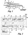
- intravascular ultrasound imaging in a patient's body 10 provides for detection of encapsulated gaseous acoustic contrast agent 11 with intravascular ultrasound.
- contrast agent particle may be used as the contrast agent 11.
- Specific acoustic signals are induced and detected from the encapsulated gas bubbles 11 using an intravascular ultrasound transducer 12.
- the induction and detection of nonlinear bubble oscillations is used to distinguish ultrasound echo signals arising from tissue (including blood) from echo signals arising from contrast agent particles.
- the ultrasound excitation signal transmitter and echo signal receiver comprises a transducer 12 mounted on a catheter 13 or guidewire introduced through a vessel 14 such as the coronary artery.
- the length of the catheter is in the range 60 to 200 cm (only partial length is shown in the figure) and the outer diameter is in the range 0.7 to 3 mm.
- a bend 5 may be formed in the distal end region of the catheter, approximately 15 to 30 mm from its tip, to provide lateral displacement of the transducer 12 to a position off the main axis of the catheter 13 and thereby closer to the walls of the vessel 14.
- the transducer 12 communicates with transmit and receive electronics via wiring 8 passing through the catheter 13.
- the transducer 12 may be used to excite and detect free contrast agent that is located in the main vessel lumen (in which the IVUS is situated), in side-branches of the main lumen, in vasa vasorum, and in other vessels or microvessels within the surrounding tissue.
- the transducer 12 may be used to excite and detect free contrast agent 11 that has selectively located to a region 15a of specific character, e.g. the vasa vasorum.
- the transducer 12 may be used to excite and detect targeted contrast agent 11 that has selectively located to target plaque-associated molecules 15b (including molecules expressed by vasa vasorum ) or to markers related to neovascularisation.
- the transducer 12 may be used to excite and detect targeted contrast agent 11 that has selectively located to target molecules 15b associated with other vascular diseases.
- the contrast agent 11 (which expression includes free bubbles) preferably comprises encapsulated bubbles that are of a composition and a size distribution capable of oscillating in a nonlinear manner at intravascular ultrasound transmit centre frequencies of at least 10 MHz, preferably in the range 10 to 80 MHz, and more preferably in the range 15 to 60 MHz, and more preferably with centre frequency above 15 MHz or above 30 MHz.
- the contrast agent bubbles 11 have compliant shells encapsulating a gaseous medium.
- the contrast agent bubbles 11 are gas-filled microvesicles stabilised by a surfactant, and in particular a phospholipid.
- the contrast agent includes a substantial proportion of bubbles having diameters less than 1.5 microns, more preferably less than 1.0 microns, and still more preferably of diameters in the range of 0.2 to 1.5 microns.
- bubbles with diameters in the specified ranges e.g.
- the bubbles form greater than 50% of the volume fraction, and more preferably greater than 70% of the volume fraction.
- contrast agent bubbles 11 can be specifically manufactured to achieve such a size distribution.
- a suitable method for preparing bubbles with the desired high volume fractions in the specified ranges is disclosed in WO 2004/069284 .
- existing commercially available contrast agent designed for use at lower frequencies but having a significant number of smaller bubbles can have its population distribution modified to some extent by decantation or mechanical filtration [13].
- the contrast agent bubbles 11 are preferably introduced into the blood stream either through a systemic steady infusion or in the form of a bolus.
- the steady state infusion may be administered through a systemic intravenous drip, as can be done for conventional frequency contrast agent use.
- the contrast agent may be introduced in combination with localised drug delivery.
- the expression "introducing contrast agent into the vicinity of the transducer" is intended to encompass both (i) 'local' introduction of the contrast agent at or very close to the transducer location, and (ii) 'remote' introduction of the contrast agent elsewhere in the body, relying on transport of the agent to the vicinity of the transducer using inherent action of the body, such as blood flow.
- the IVUS catheter 13 carrying the transducer 12 at an imaging tip 16 may be introduced into the vessel of interest 14 within a sheath or delivery catheter 17.
- the imaging tip 16 extends past the end 17a of the sheath 17 by a distance d which is preferably variable or pre-selectable.
- the distance d is in the range 10 to 300 mm.
- Contrast agent 11 may be injected locally though the sheath 17, which defines a delivery conduit 17b, to an exit orifice 17c at or proximal to the end 17a. This facilitates the delivery of a high local concentration of contrast agent 11 at the site of interest.
- the exit orifice 17c will be formed as openings in the periphery of the delivery catheter 17 so as to permit the exit of contrast agent in a manner that encourages an even agent distribution towards the vessel wall 14.
- the exit orifice 17c openings may preferably be provided within about 10 cm of the end of the sheath 17.
- a suitable remotely controllable closure mechanism may be provided to open and close the exit orifice 17c, e.g. using a control wire so that the timing of contrast agent delivery can be carefully controlled.
- the IVUS catheter 13 and its transducer 12 is integrated with the delivery conduit 17b by incorporation within the delivery sheath, it will be understood that the roles may be reversed with the delivery conduit 17b being formed within the IVUS catheter.
- the IVUS catheter 13 and delivery sheath 17 may be integrated by coupling them together side-by-side.
- the catheter-based transducer 12 may of any suitable type, e.g. comprising one or more layers of active or passive components and acoustic matching and backing layers.
- the frequency response of the transducer may have a single frequency region of efficiency or a combination or multiple peaks of efficiency.
- the transducer may have elevated efficiency around the transmitted frequency and at an integer number times this transmitted frequency and in another configuration at the transmitted frequency and at half of this frequency.
- the transducer 12 may comprise an array of transducer elements which are capable of producing an electronically steerable ultrasound excitation beam.
- the transducer 12 may comprise a mechanically manipulable single or multiple element transducer so that the direction of excitation beam can be steered or scanned during a sequence of excitation pulses.
- the transducer 12 is adapted to be capable of generating acoustic excitation pulses of sufficient pressure and other characteristics (e.g. length, frequency content) to initiate nonlinear scattering or response from the contrast agent.
- a transmit subsystem 21 is provided to generate sequences of excitation pulses 21a of sufficient amplitude characteristics (e.g. length, frequency content) to the transducer 12 in order to initiate the nonlinear scattering in the contrast agent.
- Part of the transmit subsystem may reside within the catheter 13.
- the excitation pulses are generated at frequencies greater than 10 MHz, more preferably at frequencies greater than 15 MHz.
- the excitation pulses have centre frequencies in the range 10 to 80 MHz and more preferably in the range 15 to 60 MHz.
- the excitation pulse centre frequency is in the range 15 to 50 MHz, and more preferably 15 MHz or higher, or above 30 MHz.
- Pulse sequences may be phase- and/or amplitude-modulated or frequency-band limited in order to sufficiently permit the isolation of bubble-specific scattering after reception of echo signals arising from interaction of the excitation signals with the tissue and with the contrast agent.
- any excitation pulse characteristic may be used to enable or enhance the ability to discriminate between echo signals respectively arising from interaction of ultrasound excitation signals with tissue and interaction with contrast agent.
- the sequence of excitation pulses may comprise pulses that are identical, that vary in amplitude, that vary in phase or that vary in length. Pulses may be derived from combinations of previously transmitted pulses, e.g. inverted copies and the like.
- Excitation pulses may be adapted to be used to destroy contrast agent, and to detect agent during the destruction thereof, or to use imaging pulses which follow destruction pulses.
- Part of the transmit subsystem 21 may reside within the catheter 13.
- Detection of nonlinear bubble behaviour may be achieved by way of detection of echo pulses of sufficient bandwidth, in the form of single or multiple frequency peaks, or through energy loss in the receive bandwidth or through the detection of transient bubble responses.
- a receive subsystem 22 conditions received echo signals 22a from the transducer (e.g. by amplification and filtering), digitizes the conditioned signal in a manner compatible with separating the tissue and blood signals (e.g. with sufficient phase coherence).
- Part of the receive subsystem 22 may reside within the catheter 13 which may have benefit with respect to overcoming electrical tuning effects and improving signal to noise ratio.
- Part of the system may be provided by a personal computer.
- the receive subsystem is adapted to receive echo signals in at least a part of the range 8 to 80 MHz.
- a signal processor 30 and an image processing subsystem 31 may be used to apply appropriate algorithms to extract bubble specific signals and thereby form images that have improved sensitivity and specificity to the contrast agent. It is to be understood that free bubbles located in vasa vasorum or targeted bubbles located anywhere may have specific acoustic signatures that may be exploited in transmission of excitation signals, in reception of echo signals and in signal processing.
- the echo signal analysis and imaging is performed on echo signals in a frequency band that is different to but potentially overlapping or non-overlapping with that of the transmit frequency band.
- the echo signal analysis and imaging is performed on echo signals in a frequency band comprising the second harmonic of a transmit frequency.
- the echo signal analysis and imaging is performed in a frequency band comprising a subharmonic of a transmit frequency.
- both harmonics and subharmonics are used in the echo signal analysis and imaging.
- subharmonic imaging from excitation signals having centre frequencies in the range 20 to 60 MHz is preferred, requiring for example acoustic pressures of at least 50 kPa.
- transducer layers are deployed to resonate at high frequencies, and small aperture dimensions of less than 1 mm to fit in suitable catheters 13.
- Nonlinear oscillations in contrast agent may be detected by signal changes primarily within the transmit frequency bandwidth.
- One approach for doing this is to employ power modulation approaches.
- the transmit amplitude of successive excitation pulses is varied, to result in differences in nonlinear signal generation (and thereby a corresponding reduction in the echo signals present in the transmit bandwidth).
- pulse groups are combined in such a way as to extract the nonlinear signal strength by analyzing differences in the transmit bandwidth.
- Other approaches are also possible, for example exploiting the transient response of contrast agent.
- Differentiation between contrast agent bubbles within the main vessel lumen 14 (e.g. the coronary vessel) and bubbles within vasa vasorum 15a situated in tissue immediately adjacent to the lumen 14 may be effected by using correlation-based techniques to differentiate between slowly moving bubbles 11 in the vasa vasorum 15a and more rapidly moving bubbles in the lumen 14. This may be done within a given image frame and/or between two or more consecutive image frames (frame rate is typically 20 to 30 frames per second).
- a local upstream bolus injection is used to introduce the contrast agent, this will result in a rapid passage of agent within the main lumen 14, followed by a time-delayed arrival of agent to the vasa vasorum.
- Analyzing the evolution of the signals in a region of interest (ROI) as a function of time after a bolus may therefore assist in discriminating between contrast agent in the main lumen and agent in the vasa vasorum.
- ROI region of interest
- Such approaches may use frame-to-frame image tracking due to tissue motion.
- Destruction-reperfusion techniques may also be used.
- a series of narrow bandwidth pulses (preferably at as low a frequency as achievable) is more appropriate to achieve destruction of the contrast agent bubbles.
- Imaging pulses may then follow.
- Two different transducers may be used within the catheter located at or near the imaging tip 16: a first transducer for destructive excitation pulses (e.g. with a frequency in the range 1 to 15 MHz, and preferably in the region of 5 MHz) and a second transducer for imaging, of the type described above. Imaging may be performed during destruction, or during reperfusion.
- Either transducer may be used to facilitate the targeting of contrast agent by means of radiation pressure.
- acoustic pulses will be sent out in such a way as to enhancement binding following the injection of agent. This will then be followed by pulse sequences that are appropriate for imaging the bound agent.
- Targeted and untargeted contrast agent bubbles may be differentiated using a number of techniques. Correlation-based techniques may be used to differentiate between bound and free bubbles. These techniques may be performed within a given frame and/or between two or more consecutive frames (frame rate is typically 20 to 30 frames per second). Such approaches may use frame-to-frame image tracking. Destruction techniques may be used, as previously described above. Imaging may be performed during destruction, or during re-accumulation at target sites. Differences between the acoustic response of bound and free bubbles located within the lumen may also be used.
- a waveform generator 23 provides a suitable pulse waveform to a power amplifier 24, to generate excitation signals from the transducer 16. Protection circuitry 25 in the form of an expander /limiter may be provided at the output of the power amplifier 24.
- a transmit-side filter 26 may be provided to pre-condition waveforms generated by the waveform generator 23. It will be understood that any or all of the elements 23 - 26 of the transmit subsystem 21 could be combined and/or incorporated into a single electronic circuit.
- an amplifier 27 receives echo signals 22a from the transducer 12, and passes these to a digitizer 29 for analogue-digital conversion.
- the digitised signals are passed to a signal processor 30 (which may be incorporated within a personal computer.
- the signal processor 30 may include, or be coupled to an appropriate image processing device 31, which also may be incorporated within a personal computer.
- An analogue filter 28 may be incorporated in the receive path, e.g. before and/or after amplification of the received echo signals. It will be understood that any or all of the elements 27 - 30 of the receive sub-system 22 could be combined and/or incorporated into a single electronic circuit.
- a flow phantom was constructed by creating a 1 mm flow channel through tissue mimicking phantom, and contrast agent was passed through this 'vessel' during the experiments.
- the contrast agent employed was an experimental phospholipid-stabilized composition prepared according to example 1i of WO 2004/069284 .
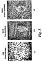
- Images were constructed by pulse-inversion techniques from a series of pulse ensembles (10 or 25% bandwidth) acquired during continuous translation. The pulse-inversion technique effects cancellation of linear signals by exploiting differences in consecutive phase-inversed pulses due to nonlinear propagation or bubble responses. If there is substantial motion between the tissue and transducer between pulses, this will result in inefficient cancellation of the fundamental frequency.
- a needle-mounted IVUS transducer was employed (having a bandwidth of 15 to 45 MHz) to image free bubbles flowing freely through the vessel.
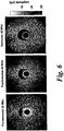
- the vessel was first imaged in 20 MHz fundamental mode (F20), which is linear imaging.
- the vessel was then imaged using the second harmonic of a 20 MHz transmit pulse (H40), and finally using the subharmonic of a 40 MHz transmit pulse, centred closer to 20 MHz (S20).
- F20 imaging shows little contrast between tissue and agent flowing in the vessel ( figure 3a ).
- H40 was found to produce improvements in contrast to tissue signal ratios (CTR).
- CTR tissue signal ratios
- the CTR degrades due to increases in nonlinear propagation giving rise to a stronger tissue harmonic signal. This indicates that lower pressure ranges will be appropriate for contrast agent imaging, and higher pressure amplitudes are appropriate for tissue harmonic imaging.
- the fundamental frequency image, F40 ( figure 4a ) offers poor visualization of the vessel.
- F40 ( figure 4a ) offers poor visualization of the vessel.
- SH20 mode results indicate tissue suppression approaching the noise floor, with up to 18 dB of contrast to noise ratio at higher transmit amplitudes.
- These results indicate the feasibility of nonlinear contrast imaging with IVUS.
- the feasibility to suppress tissue signals is critical in reliably detecting vasa vasorum with IVUS.
- figure 5a shows F20 imaging of free flowing bubbles
- figure 5b shows SH10 imaging of free flowing bubbles
- figure 5c shows SH10 imaging of bound bubbles.
- the imaging techniques using a catheter-based ultrasound probe may be used to assist in localised drug delivery by providing real-time image guidance to the drug delivery mechanism.
- the drug delivery mechanism may be incorporated with the contrast agent.
- Drugs or genetic material may be incorporated into, located within or in some manner attached to or imbedded in the contrast agent.
- the catheter-based IVUS transducer can be used to assess an appropriate location for drug or genetic material delivery and to facilitate its delivery.
- the delivery may be facilitated by the acoustic stimulation of either the imaging transducer or the second lower frequency transducer, if present.
- the acoustic stimulation may effect the disruption of contrast agent which contains drug or genetic material, or contrast agent that is in the presence of drug or genetic material.
- This may involve the stimulation of oscillations of contrast agent which contains drug or genetic material, or contrast agent that is in the presence of drug or genetic material, in a manner that facilitates the delivery of the drug or genetic material to the tissue or cells of interest.
- a two transducer approach is employed such that the lower frequency (1 to 15 MHz transducer) is used to facilitate the delivery of drug or genetic material, and the second transducer, the imaging transducer, being used to guide or monitor the treatment procedure.
- the contrast agent delivery system using conduit 17b formed by sheath 17 may also be configured with means for applying a saline (or heparinized saline) flush between contrast injections.
- the delivery system conduit may also be provided with a means (not shown) for displacing a smaller volume of agent to the catheter tip, particularly if the volume of the catheter sheath 17 may exceed the desired injection volume.
- existing syringe adaptors may be used to manually introduce the agent and saline flushes.
- An exemplary automated implementation consists of a two-plunger syringe pump (one for a saline syringe and the second for the agent).
- the agent injection volume and injection rate can be specified and the agent can then automatically be pushed slowly (to avoid pressurization of agent that would cause its disruption) towards the catheter tip. This can then be followed by the bolus injection phase (the timing of which may be electronically synchronised with the IVUS imaging and acquisition system.
- pulse centre frequencies in the range of 15 to 30 MHz, with total pulse frequency content between 5 and 60 MHz is preferred.
- Peak positive acoustic pressures within the beam lie between 5 kPa and 1 MPa for contrast imaging mode.
- Peak positive acoustic pressures within the beam lie between 100 kPa and 10 MPa when operating in tissue harmonic imaging mode.
- pulse centre frequencies in the range of 30 to 60 MHz, with total pulse frequency content between 10 and 80 MHz is preferred.
- Peak positive acoustic pressures within the beam lie between 20 kPa and 8 MPa when operating in contrast imaging mode.
- pulse centre frequencies in the range of 20 to 50 MHz, with total pulse frequency content between 10 and 80 MHz is preferred.
- Peak positive acoustic pressures within the beam lie between 5 kPa and 8 MPa when operating in contrast imaging mode.
- pulse centre frequencies in the range of 20 to 50 MHz, with total pulse frequency content between 10 and 80 MHz is preferred.
- Peak positive acoustic pressures within the beam lie between 5 kPa and 8 MPa.
- a destruction pulse mode using a single element transducer transmit centre frequencies in the range of 10 to 40 MHz, with pulse bandwidths between 0.1 % and 50 %-6 dB relative bandwidths are preferred. Peak positive acoustic pressures within the beam (as measured in a water tank) lie between 100 kPa and 15 MPa.
- pulse centre frequencies in the range of 1 to 15 MHz, with pulse bandwidths lying between 0.1 % and 50 %-6 dB relative bandwidths are preferred.
- Peak positive acoustic pressures within the beam lie between 100 kPa and 15 MPa.
- pulse centre frequencies in the range of 1 to 15 MHz, with pulse bandwidths between 0.1 % and 50 % -6 dB relative bandwidths are preferred.
- Peak positive acoustic pressures within the beam lie between 100 kPa and 5 MPa.
- pulse centre frequencies for the low frequency element in range of 1 to 15 MHz and pulse centre frequencies for high frequency element in range of 15 to 50 MHz, with pulse bandwidths between 0.1 % and 20 % -6 dB relative bandwidths are preferred.
- Peak positive acoustic pressures within the beam lie between 100 kPa and 5 MPa.
- agent detection is achieved by means of the nonlinear behaviour of bubbles.
- the nonlinear signals are isolated by means of filtering and analysis of pulse sequences. Individual transmitted pulses have characteristics that fall within the range of those described above.
- the expression 'pulse sequence' refers to a sequence of potentially different pulses that are transmitted and received as the transducer is rotating.
- Nonlinear echo signals at subharmonic or second harmonic frequencies are isolated by a combination of analog and digital filtering of the individual received echo signals.
- a single IVUS image is formed by taking the envelope of individual RF lines displayed in a linear, logarithmic or other compression scheme.
- the signals from a group of adjacent pulses are combined to form an image line, and in doing so benefit from signal averaging effects.
- the combination may take the form of direct averaging of the time domain, or power averaging or another scheme.
- Transmitted pulses may also be phase-inversed (i.e. have 180 degree phase differences) with respect to each other.
- a group of these pulses (two or more) may be combined to form an image line as a strategy for removing linear tissue signals.
- the operation to combine the pulses may take different forms, only one of which is to sum with equal weighting all the pulses.
- Transmitted pulses may also be phase shifted with respect to each other by an amount other than 180 degrees (e.g. 90 degrees).
- a group of these pulses (two or more) may be combined to form an image line as a strategy for removing linear tissue signals.
- the operation to combine the pulses may take different forms, only one of which is to sum with equal weighting all the pulses.
- Pulses may be transmitted with different amplitudes, referred to as power modulation. This will vary the amount of nonlinear bubble behaviour.
- a group of these pulses (two or more) may be combined to form an image line as a strategy for removing linear tissue signals.
- the operation to combine the pulses may take different forms. For example, if two pulses are transmitted, the first with half the amplitude of the second, then the received pulse pair is added by multiplying the first pulse by two before subtracting it from the second.
- Transmitted combinations of phase and amplitude modulation may be used to isolate nonlinear signals.
- Transmit pulse lengths may be varied.
- the received signals may then be processed to extract nonlinear transients or other pulse length dependant signals arising from bubble oscillations.
- Transmit frequency may be varied within a pulse.
- the received signals may then be processed to extract signals arising from bubble oscillations.
- Formation of images from the imaging transducer received signals when the transmit pulses are sent out by either the imaging transducer or a separate low frequency transducer to destroy agent may be effected in several ways, both for when destructive pulses are transmitted by the imaging transducer, or by a separate low frequency transducer.
- one or more entire rotations of the IVUS element can be conducted during which time high amplitude pulses are sent with the intention of destroying free or targeted agent with either transducer. Following the destructive frames, imaging is then performed using one of the methods described above. This can be used as a means of implementing destruction-reperfusion imaging or to assess re-accumulation of targeted agent.
- the changes of signals as a function of time in regions of interest may be used to differentiate agent located in vasa vasorum or targeted agent from free agent within the main lumen.
- targeted agent a different pressure, bandwidth and frequency range may be employed as a means of distinguishing targeted agent from bound agent.
- Pulse sequences may consist of non-destructive (or predominantly non-destructive) pulses sent on the low frequency transducer and nonlinear signals detected by the imaging transducer. These signals may include superharmonics, ultraharmonics or transients.
- Pulse sequences may consist of the simultaneous transmitting of different pulses on both the imaging transducer and the low frequency transducer.
- tissue imaging mode By being able to operate in either mode it is possible to superimpose contrast specific signals onto tissue structural images.
- Tissue signals may be isolated from the incoming received signals (which may also contain contrast-specific signals) through processing.
- tissue signals may be extracted from modifications of the pulse sequences (i.e. both transmit pulse characteristics and amplitudes) that would allow for tissue imaging pulses to be interleaved with contrast imaging pulses.
- Tissue imaging can be performed in linear or nonlinear imaging modes. Multiple pulse techniques such as pulse-inversion imaging or amplitude modulation can also be applied to nonlinear tissue imaging (both in the presence of contrast agent or not).
- the multiple pulse techniques will be optimised so that the level of harmonics generated are maximized, or are maximized after a certain distance, or to maximize the contrast in between tissue components.
- tissue harmonic imaging was illustrated on a continuously rotating single element transducer in a tissue mimicking phantom and in an atherosclerotic rabbit aorta.
- Gaussian enveloped pulses at centre frequencies of either 20 MHz or 40 MHz were generated. The fractional bandwidth of the pulses was 25 %.
- F20 fundamental 20 MHz mode
- F40 fundamental 40 MHz mode
- H40 harmonic 40 MHz mode
- SNR signal-to-noise ratio
- tissue harmonic imaging using pulse inversion has shown to be feasible in a tissue mimicking phantom and to improve image quality.
- tissue harmonic imaging using pulse inversion has shown to be feasible in vivo and to improve image quality.
Applications Claiming Priority (2)
| Application Number | Priority Date | Filing Date | Title |
|---|---|---|---|
| GB0418118A GB2417080B (en) | 2004-08-13 | 2004-08-13 | Intravascular ultrasound techniques |
| PCT/EP2005/008797 WO2006015877A1 (en) | 2004-08-13 | 2005-08-11 | Intravascular ultrasound techniques |
Publications (2)
| Publication Number | Publication Date |
|---|---|
| EP1793741A1 EP1793741A1 (en) | 2007-06-13 |
| EP1793741B1 true EP1793741B1 (en) | 2012-04-11 |
Family
ID=33017489
Family Applications (1)
| Application Number | Title | Priority Date | Filing Date |
|---|---|---|---|
| EP05770290A Active EP1793741B1 (en) | 2004-08-13 | 2005-08-11 | Intravascular ultrasound techniques |
Country Status (6)
| Country | Link |
|---|---|
| US (1) | US8454520B2 (ja) |
| EP (1) | EP1793741B1 (ja) |
| JP (1) | JP5103180B2 (ja) |
| AT (1) | ATE552782T1 (ja) |
| GB (2) | GB2417080B (ja) |
| WO (2) | WO2006015877A1 (ja) |
Families Citing this family (57)
| Publication number | Priority date | Publication date | Assignee | Title |
|---|---|---|---|---|
| US7510536B2 (en) * | 1999-09-17 | 2009-03-31 | University Of Washington | Ultrasound guided high intensity focused ultrasound treatment of nerves |
| US7520856B2 (en) * | 1999-09-17 | 2009-04-21 | University Of Washington | Image guided high intensity focused ultrasound device for therapy in obstetrics and gynecology |
| JP2003513691A (ja) | 1999-10-25 | 2003-04-15 | シーラス、コーポレイション | 血管を封止するための集束超音波の使用 |
| US6626855B1 (en) | 1999-11-26 | 2003-09-30 | Therus Corpoation | Controlled high efficiency lesion formation using high intensity ultrasound |
| WO2005037060A2 (en) * | 2003-10-03 | 2005-04-28 | University Of Washington | Transcutaneous localization of arterial bleeding by ultrasonic imaging |
| US20110040171A1 (en) * | 2003-12-16 | 2011-02-17 | University Of Washington | Image guided high intensity focused ultrasound treatment of nerves |
| US8708909B2 (en) | 2004-01-20 | 2014-04-29 | Fujifilm Visualsonics, Inc. | High frequency ultrasound imaging using contrast agents |
| WO2007001352A2 (en) * | 2004-08-31 | 2007-01-04 | University Of Washington | Ultrasonic technique for assessing wall vibrations in stenosed blood vessels |
| US9066679B2 (en) * | 2004-08-31 | 2015-06-30 | University Of Washington | Ultrasonic technique for assessing wall vibrations in stenosed blood vessels |
| CA2575687A1 (en) * | 2004-09-16 | 2006-03-23 | University Of Washington | Acoustic coupler using an independent water pillow with circulation for cooling a transducer |
| DE102005019371B4 (de) * | 2005-04-26 | 2009-04-09 | Siemens Ag | Bildaufnahmeeinrichtung zur Aufnahme von Ultraschallbildern |
| WO2007021958A2 (en) * | 2005-08-12 | 2007-02-22 | University Of Washington | Method and apparatus for preparing organs and tissues for laparoscopic surgery |
| WO2007035529A2 (en) * | 2005-09-16 | 2007-03-29 | University Of Washington | Thin-profile therapeutic ultrasound applicators |
| US7998076B2 (en) * | 2005-09-27 | 2011-08-16 | Siemens Medical Solutions Usa, Inc. | Advanced characterization of contrast agents with ultrasound |
| US8016757B2 (en) * | 2005-09-30 | 2011-09-13 | University Of Washington | Non-invasive temperature estimation technique for HIFU therapy monitoring using backscattered ultrasound |
| US20070233185A1 (en) | 2005-10-20 | 2007-10-04 | Thomas Anderson | Systems and methods for sealing a vascular opening |
| WO2008016992A1 (en) | 2006-08-01 | 2008-02-07 | Scimed Life Systems, Inc. | Pulse inversion sequences for nonlinear imaging |
| US20090234231A1 (en) * | 2008-03-13 | 2009-09-17 | Knight Jon M | Imaging Catheter With Integrated Contrast Agent Injector |
| US8197413B2 (en) * | 2008-06-06 | 2012-06-12 | Boston Scientific Scimed, Inc. | Transducers, devices and systems containing the transducers, and methods of manufacture |
| CN102458257A (zh) * | 2009-04-17 | 2012-05-16 | 视声公司 | 在高频率下用于超声造影剂非线性成像的方法 |
| CN101897597B (zh) * | 2009-05-25 | 2013-09-04 | 深圳迈瑞生物医疗电子股份有限公司 | 超声成像的方法和装置 |
| US20160059044A1 (en) | 2009-10-12 | 2016-03-03 | Kona Medical, Inc. | Energy delivery to intraparenchymal regions of the kidney to treat hypertension |
| US20110118600A1 (en) | 2009-11-16 | 2011-05-19 | Michael Gertner | External Autonomic Modulation |
| US9808222B2 (en) | 2009-10-12 | 2017-11-07 | Acist Medical Systems, Inc. | Intravascular ultrasound system for co-registered imaging |
| US8295912B2 (en) | 2009-10-12 | 2012-10-23 | Kona Medical, Inc. | Method and system to inhibit a function of a nerve traveling with an artery |
| US8517962B2 (en) | 2009-10-12 | 2013-08-27 | Kona Medical, Inc. | Energetic modulation of nerves |
| US9119951B2 (en) | 2009-10-12 | 2015-09-01 | Kona Medical, Inc. | Energetic modulation of nerves |
| US8986231B2 (en) | 2009-10-12 | 2015-03-24 | Kona Medical, Inc. | Energetic modulation of nerves |
| US20110092880A1 (en) | 2009-10-12 | 2011-04-21 | Michael Gertner | Energetic modulation of nerves |
| US9174065B2 (en) | 2009-10-12 | 2015-11-03 | Kona Medical, Inc. | Energetic modulation of nerves |
| US8469904B2 (en) | 2009-10-12 | 2013-06-25 | Kona Medical, Inc. | Energetic modulation of nerves |
| US8986211B2 (en) | 2009-10-12 | 2015-03-24 | Kona Medical, Inc. | Energetic modulation of nerves |
| JP4734448B2 (ja) * | 2009-12-04 | 2011-07-27 | 株式会社日立製作所 | 超音波治療装置 |
| WO2011135275A1 (en) * | 2010-04-29 | 2011-11-03 | Imperial Innovations Limited | Method and microbubbles for detecting atherosclerotic plaque |
| JP2013541392A (ja) * | 2010-11-08 | 2013-11-14 | コリブリ テクノロジーズ インコーポレーテッド | 低侵襲処置の間の改善された視覚化のためのシステム及び方法 |
| US9216008B2 (en) | 2012-01-30 | 2015-12-22 | Technion Research & Development Foundation Limited | Quantitative assessment of neovascularization |
| WO2014100217A1 (en) * | 2012-12-21 | 2014-06-26 | Volcano Corporation | Method for multi-frequency imaging using high-bandwidth transducer outputs |
| US9693754B2 (en) | 2013-05-15 | 2017-07-04 | Acist Medical Systems, Inc. | Imaging processing systems and methods |
| JP6353038B2 (ja) | 2013-10-07 | 2018-07-04 | アシスト・メディカル・システムズ,インコーポレイテッド | 血管内撮像の信号処理 |
| US20150196271A1 (en) * | 2014-01-10 | 2015-07-16 | Volcano Corporation | Detecting endoleaks associated with aneurysm repair |
| CN105899141A (zh) * | 2014-01-10 | 2016-08-24 | 火山公司 | 检测与动脉瘤修复相关联的内漏 |
| RU2690445C2 (ru) | 2014-01-23 | 2019-06-03 | Конинклейке Филипс Н.В. | Оценка каротидной бляшки с применением ультразвуковой визуализации с контрастированием |
| US11076830B2 (en) * | 2014-09-02 | 2021-08-03 | Samsung Electronics Co., Ltd. | Ultrasound imaging apparatus and method of controlling the same |
| KR102493397B1 (ko) * | 2014-09-02 | 2023-01-31 | 삼성전자주식회사 | 초음파 영상 장치 및 그 제어 방법 |
| US10925579B2 (en) | 2014-11-05 | 2021-02-23 | Otsuka Medical Devices Co., Ltd. | Systems and methods for real-time tracking of a target tissue using imaging before and during therapy delivery |
| US10653393B2 (en) | 2015-10-08 | 2020-05-19 | Acist Medical Systems, Inc. | Intravascular ultrasound imaging with frequency selective imaging methods and systems |
| US10909661B2 (en) | 2015-10-08 | 2021-02-02 | Acist Medical Systems, Inc. | Systems and methods to reduce near-field artifacts |
| US11369337B2 (en) | 2015-12-11 | 2022-06-28 | Acist Medical Systems, Inc. | Detection of disturbed blood flow |
| JP7104632B2 (ja) | 2015-12-31 | 2022-07-21 | アシスト・メディカル・システムズ,インコーポレイテッド | 半自動化画像セグメント化システム及び方法 |
| JP7152955B2 (ja) | 2016-05-16 | 2022-10-13 | アシスト・メディカル・システムズ,インコーポレイテッド | 動作ベースの画像セグメント化のシステムおよび方法 |
| US10492760B2 (en) | 2017-06-26 | 2019-12-03 | Andreas Hadjicostis | Image guided intravascular therapy catheter utilizing a thin chip multiplexor |
| US10188368B2 (en) * | 2017-06-26 | 2019-01-29 | Andreas Hadjicostis | Image guided intravascular therapy catheter utilizing a thin chip multiplexor |
| US11109909B1 (en) | 2017-06-26 | 2021-09-07 | Andreas Hadjicostis | Image guided intravascular therapy catheter utilizing a thin ablation electrode |
| WO2019119400A1 (zh) * | 2017-12-22 | 2019-06-27 | 深圳先进技术研究院 | 一种双频率血管内超声成像探头 |
| US20220218312A1 (en) * | 2019-06-11 | 2022-07-14 | Koninklijke Philips N.V. | Temporally balanced multi-mode master imaging sequence for ultrasonic contrast imaging |
| US11024034B2 (en) | 2019-07-02 | 2021-06-01 | Acist Medical Systems, Inc. | Image segmentation confidence determination |
| CN114145713A (zh) * | 2021-11-30 | 2022-03-08 | 深圳先进技术研究院 | 一种双频内窥导管及成像装置 |
Citations (1)
| Publication number | Priority date | Publication date | Assignee | Title |
|---|---|---|---|---|
| US20020188200A1 (en) * | 2001-06-08 | 2002-12-12 | Pascal Mauchamp | Multi-purpose ultrasonic slotted array transducer |
Family Cites Families (47)
| Publication number | Priority date | Publication date | Assignee | Title |
|---|---|---|---|---|
| US5203992A (en) | 1989-06-23 | 1993-04-20 | Hewlett-Packard Company | Apparatus for optimizing the liquid chromatographic separation of a sample |
| US5476100A (en) * | 1994-07-07 | 1995-12-19 | Guided Medical Systems, Inc. | Catheter steerable by directional jets with remotely controlled closures |
| US5115814A (en) * | 1989-08-18 | 1992-05-26 | Intertherapy, Inc. | Intravascular ultrasonic imaging probe and methods of using same |
| US5556610A (en) | 1992-01-24 | 1996-09-17 | Bracco Research S.A. | Gas mixtures useful as ultrasound contrast media, contrast agents containing the media and method |
| US5445813A (en) | 1992-11-02 | 1995-08-29 | Bracco International B.V. | Stable microbubble suspensions as enhancement agents for ultrasound echography |
| IN172208B (ja) | 1990-04-02 | 1993-05-01 | Sint Sa | |
| AU636481B2 (en) | 1990-05-18 | 1993-04-29 | Bracco International B.V. | Polymeric gas or air filled microballoons usable as suspensions in liquid carriers for ultrasonic echography |
| JP3367666B2 (ja) * | 1990-12-17 | 2003-01-14 | カーディオヴァスキュラー イメイジング システムズ インコーポレイテッド | 低輪郭の遠位端部を有する血管カテーテル |
| US5203337A (en) * | 1991-05-08 | 1993-04-20 | Brigham And Women's Hospital, Inc. | Coronary artery imaging system |
| IL104084A (en) | 1992-01-24 | 1996-09-12 | Bracco Int Bv | Sustainable aqueous suspensions of pressure-resistant and gas-filled blisters, their preparation, and contrast agents containing them |
| US5713848A (en) * | 1993-05-19 | 1998-02-03 | Dubrul; Will R. | Vibrating catheter |
| US5840031A (en) * | 1993-07-01 | 1998-11-24 | Boston Scientific Corporation | Catheters for imaging, sensing electrical potentials and ablating tissue |
| US5531679A (en) * | 1994-03-14 | 1996-07-02 | Schulman; Joseph H. | Fluidic infusion system for catheter or probe |
| US5549111A (en) * | 1994-08-05 | 1996-08-27 | Acuson Corporation | Method and apparatus for adjustable frequency scanning in ultrasound imaging |
| US6333021B1 (en) | 1994-11-22 | 2001-12-25 | Bracco Research S.A. | Microcapsules, method of making and their use |
| IL116328A (en) | 1994-12-16 | 1999-09-22 | Bracco Research Sa | Frozen suspension of gas microbubbles in frozen aqueous carrier for use as contrast agent in ultrasonic imaging |
| US6321109B2 (en) * | 1996-02-15 | 2001-11-20 | Biosense, Inc. | Catheter based surgery |
| US5749364A (en) * | 1996-06-21 | 1998-05-12 | Acuson Corporation | Method and apparatus for mapping pressure and tissue properties |
| JP3502727B2 (ja) * | 1996-09-19 | 2004-03-02 | ジーイー横河メディカルシステム株式会社 | 超音波撮像装置 |
| US5848969A (en) * | 1996-10-28 | 1998-12-15 | Ep Technologies, Inc. | Systems and methods for visualizing interior tissue regions using expandable imaging structures |
| US5752518A (en) * | 1996-10-28 | 1998-05-19 | Ep Technologies, Inc. | Systems and methods for visualizing interior regions of the body |
| US5797858A (en) * | 1997-03-14 | 1998-08-25 | Hewlett-Packard Company | Spooling pullback for catheter imaging and therapy cores |
| US5833615A (en) * | 1997-05-09 | 1998-11-10 | Thomas Jefferson University | Excitation enhanced ultrasound system |
| US5944666A (en) * | 1997-08-21 | 1999-08-31 | Acuson Corporation | Ultrasonic method for imaging blood flow including disruption or activation of contrast agent |
| JPH11178826A (ja) * | 1997-12-22 | 1999-07-06 | Aloka Co Ltd | 超音波探触子 |
| JP3984698B2 (ja) | 1998-03-12 | 2007-10-03 | ジーイー横河メディカルシステム株式会社 | 超音波撮像装置 |
| US6066096A (en) * | 1998-05-08 | 2000-05-23 | Duke University | Imaging probes and catheters for volumetric intraluminal ultrasound imaging and related systems |
| US6001062A (en) * | 1998-08-03 | 1999-12-14 | Scimed Life Systems, Inc. | Slewing bandpass filter for selective passage of time varying acoustic signals |
| US6645147B1 (en) * | 1998-11-25 | 2003-11-11 | Acuson Corporation | Diagnostic medical ultrasound image and system for contrast agent imaging |
| US6171246B1 (en) * | 1999-04-29 | 2001-01-09 | Michalakis Averkiou | Realtime ultrasonic imaging of perfusion using ultrasonic contrast agents |
| US6423002B1 (en) * | 1999-06-24 | 2002-07-23 | Acuson Corporation | Intra-operative diagnostic ultrasound multiple-array transducer probe and optional surgical tool |
| US6443894B1 (en) * | 1999-09-29 | 2002-09-03 | Acuson Corporation | Medical diagnostic ultrasound system and method for mapping surface data for three dimensional imaging |
| JP3300313B2 (ja) * | 1999-11-01 | 2002-07-08 | 松下電器産業株式会社 | 超音波診断装置 |
| US6494841B1 (en) * | 2000-02-29 | 2002-12-17 | Acuson Corporation | Medical diagnostic ultrasound system using contrast pulse sequence imaging |
| US6612992B1 (en) * | 2000-03-02 | 2003-09-02 | Acuson Corp | Medical diagnostic ultrasound catheter and method for position determination |
| JP4567842B2 (ja) * | 2000-04-10 | 2010-10-20 | 株式会社東芝 | 超音波診断装置 |
| CA2312142A1 (en) * | 2000-06-22 | 2001-12-22 | An-Go-Gen Inc. | Injection system for gene delivery |
| JP2002102229A (ja) * | 2000-09-29 | 2002-04-09 | Fuji Photo Optical Co Ltd | 超音波プローブ |
| JP2002306472A (ja) * | 2001-04-11 | 2002-10-22 | Hitachi Medical Corp | 超音波診断装置 |
| JP3533406B2 (ja) * | 2001-07-02 | 2004-05-31 | コーリンメディカルテクノロジー株式会社 | 動脈硬化評価装置 |
| DE60213457T2 (de) * | 2001-12-03 | 2007-10-18 | Ekos Corp., Bothell | Ultraschallkatheter für kleine gefässe |
| US6746401B2 (en) * | 2002-05-06 | 2004-06-08 | Scimed Life Systems, Inc. | Tissue ablation visualization |
| JP3785128B2 (ja) * | 2002-09-19 | 2006-06-14 | 株式会社東芝 | 画像診断装置、画像処理方法、画像処理装置及び記憶媒体 |
| US7250041B2 (en) * | 2003-03-12 | 2007-07-31 | Abbott Cardiovascular Systems Inc. | Retrograde pressure regulated infusion |
| WO2005042079A1 (en) * | 2003-10-31 | 2005-05-12 | Trudell Medical International | System and method for manipulating a catheter for delivering a substance to a body cavity |
| US20050124895A1 (en) * | 2003-12-05 | 2005-06-09 | Koninklijke Philips Electronics N.V. | Ultrasonic speckle reduction using nonlinear echo combinations |
| US7025726B2 (en) * | 2004-01-22 | 2006-04-11 | The Regents Of The University Of Nebraska | Detection of endothelial dysfunction by ultrasonic imaging |
-
2004
- 2004-08-13 GB GB0418118A patent/GB2417080B/en not_active Expired - Fee Related
- 2004-08-13 GB GB0806499A patent/GB2445322B/en not_active Expired - Fee Related
-
2005
- 2005-08-11 EP EP05770290A patent/EP1793741B1/en active Active
- 2005-08-11 US US11/660,301 patent/US8454520B2/en active Active
- 2005-08-11 WO PCT/EP2005/008797 patent/WO2006015877A1/en active Application Filing
- 2005-08-11 WO PCT/EP2005/008796 patent/WO2006015876A2/en active Application Filing
- 2005-08-11 AT AT05770290T patent/ATE552782T1/de active
- 2005-08-11 JP JP2007525266A patent/JP5103180B2/ja active Active
Patent Citations (1)
| Publication number | Priority date | Publication date | Assignee | Title |
|---|---|---|---|---|
| US20020188200A1 (en) * | 2001-06-08 | 2002-12-12 | Pascal Mauchamp | Multi-purpose ultrasonic slotted array transducer |
Non-Patent Citations (1)
| Title |
|---|
| FORSBERG F ET AL: "Contrast enhanced vascular three-dimensional ultrasound imaging", ULTRASONICS, IPC SCIENCE AND TECHNOLOGY PRESS LTD. GUILDFORD, GB, vol. 40, no. 1-8, 1 May 2002 (2002-05-01), pages 117 - 122, XP004357180, ISSN: 0041-624X, DOI: DOI:10.1016/S0041-624X(02)00099-9 * |
Also Published As
| Publication number | Publication date |
|---|---|
| GB2417080B (en) | 2008-05-21 |
| GB2417080A (en) | 2006-02-15 |
| US20080200815A1 (en) | 2008-08-21 |
| GB0806499D0 (en) | 2008-05-14 |
| GB0418118D0 (en) | 2004-09-15 |
| JP5103180B2 (ja) | 2012-12-19 |
| JP2008508970A (ja) | 2008-03-27 |
| WO2006015877A1 (en) | 2006-02-16 |
| GB2445322B (en) | 2008-08-06 |
| ATE552782T1 (de) | 2012-04-15 |
| GB2445322A (en) | 2008-07-02 |
| WO2006015876A2 (en) | 2006-02-16 |
| US8454520B2 (en) | 2013-06-04 |
| EP1793741A1 (en) | 2007-06-13 |
Similar Documents
| Publication | Publication Date | Title |
|---|---|---|
| EP1793741B1 (en) | Intravascular ultrasound techniques | |
| Klibanov et al. | Ultrasound in radiology: from anatomic, functional, molecular imaging to drug delivery and image-guided therapy | |
| Harvey et al. | Advances in ultrasound | |
| US5558092A (en) | Methods and apparatus for performing diagnostic and therapeutic ultrasound simultaneously | |
| US6464680B1 (en) | Ultrasonic enhancement of drug injection | |
| US9532769B2 (en) | Systems, methods, and computer readable media for high frequency contrast imaging and image-guided therapeutics | |
| US20100312117A1 (en) | Ultrasonic visualization of percutaneous needles, intravascular catheters and other invasive devices | |
| JP5925193B2 (ja) | 経皮的針、血管内カテーテル及び他の侵襲的デバイスの超音波視覚化 | |
| JP5154554B2 (ja) | 非線形イメージングのためのパルスインバージョンシーケンス | |
| Hu et al. | A sensitive TLRH targeted imaging technique for ultrasonic molecular imaging | |
| WO2013181194A1 (en) | Catheter device implementing high frequency, contrast imaging ultrasound transducer, and associated method | |
| Azhari | Ultrasound: medical imaging and beyond (an invited review) | |
| Kusunose et al. | Fast, low-frequency plane-wave imaging for ultrasound contrast imaging | |
| JP7104709B2 (ja) | 圧力測定のための非侵襲法 | |
| Hossack | Therapeutic IVUS and Contrast Imaging | |
| AU736153B2 (en) | Methods and apparatus for performing diagnostic and therapeutic ultrasound simultaneously | |
| Kilroy | Intravascular Ultrasound Transducers for Microbubble-Mediated Therapy | |
| Mannaris | Ultrasound enhanced drug delivery: pressure and temperature activation approaches | |
| Hu | The Development of Ultrasound Molecular Imaging | |
| Dayton et al. | Piezoelectric Composite Micromachined Multifrequency Transducers for High-Resolution, High-Contrast Ultrasound Imaging for Improved Prostate Cancer Assessment | |
| Daeichin | Micro-Ultrasound Molecular Imaging | |
| Frijlink | Harmonic Intravascular Ultrasound | |
| Harvey et al. | Ultrasound: Future Directions |
Legal Events
| Date | Code | Title | Description |
|---|---|---|---|
| PUAI | Public reference made under article 153(3) epc to a published international application that has entered the european phase |
Free format text: ORIGINAL CODE: 0009012 |
|
| 17P | Request for examination filed |
Effective date: 20070313 |
|
| AK | Designated contracting states |
Kind code of ref document: A1 Designated state(s): AT BE BG CH CY CZ DE DK EE ES FI FR GB GR HU IE IS IT LI LT LU LV MC NL PL PT RO SE SI SK TR |
|
| DAX | Request for extension of the european patent (deleted) | ||
| 17Q | First examination report despatched |
Effective date: 20071123 |
|
| GRAP | Despatch of communication of intention to grant a patent |
Free format text: ORIGINAL CODE: EPIDOSNIGR1 |
|
| GRAJ | Information related to disapproval of communication of intention to grant by the applicant or resumption of examination proceedings by the epo deleted |
Free format text: ORIGINAL CODE: EPIDOSDIGR1 |
|
| GRAP | Despatch of communication of intention to grant a patent |
Free format text: ORIGINAL CODE: EPIDOSNIGR1 |
|
| GRAS | Grant fee paid |
Free format text: ORIGINAL CODE: EPIDOSNIGR3 |
|
| GRAA | (expected) grant |
Free format text: ORIGINAL CODE: 0009210 |
|
| AK | Designated contracting states |
Kind code of ref document: B1 Designated state(s): AT BE BG CH CY CZ DE DK EE ES FI FR GB GR HU IE IS IT LI LT LU LV MC NL PL PT RO SE SI SK TR |
|
| REG | Reference to a national code |
Ref country code: GB Ref legal event code: FG4D |
|
| REG | Reference to a national code |
Ref country code: CH Ref legal event code: EP |
|
| REG | Reference to a national code |
Ref country code: AT Ref legal event code: REF Ref document number: 552782 Country of ref document: AT Kind code of ref document: T Effective date: 20120415 |
|
| REG | Reference to a national code |
Ref country code: IE Ref legal event code: FG4D |
|
| REG | Reference to a national code |
Ref country code: DE Ref legal event code: R096 Ref document number: 602005033637 Country of ref document: DE Effective date: 20120606 |
|
| REG | Reference to a national code |
Ref country code: NL Ref legal event code: T3 |
|
| REG | Reference to a national code |
Ref country code: AT Ref legal event code: MK05 Ref document number: 552782 Country of ref document: AT Kind code of ref document: T Effective date: 20120411 |
|
| LTIE | Lt: invalidation of european patent or patent extension |
Effective date: 20120411 |
|
| PG25 | Lapsed in a contracting state [announced via postgrant information from national office to epo] |
Ref country code: CY Free format text: LAPSE BECAUSE OF FAILURE TO SUBMIT A TRANSLATION OF THE DESCRIPTION OR TO PAY THE FEE WITHIN THE PRESCRIBED TIME-LIMIT Effective date: 20120411 Ref country code: LT Free format text: LAPSE BECAUSE OF FAILURE TO SUBMIT A TRANSLATION OF THE DESCRIPTION OR TO PAY THE FEE WITHIN THE PRESCRIBED TIME-LIMIT Effective date: 20120411 Ref country code: FI Free format text: LAPSE BECAUSE OF FAILURE TO SUBMIT A TRANSLATION OF THE DESCRIPTION OR TO PAY THE FEE WITHIN THE PRESCRIBED TIME-LIMIT Effective date: 20120411 Ref country code: PL Free format text: LAPSE BECAUSE OF FAILURE TO SUBMIT A TRANSLATION OF THE DESCRIPTION OR TO PAY THE FEE WITHIN THE PRESCRIBED TIME-LIMIT Effective date: 20120411 Ref country code: IS Free format text: LAPSE BECAUSE OF FAILURE TO SUBMIT A TRANSLATION OF THE DESCRIPTION OR TO PAY THE FEE WITHIN THE PRESCRIBED TIME-LIMIT Effective date: 20120811 Ref country code: SE Free format text: LAPSE BECAUSE OF FAILURE TO SUBMIT A TRANSLATION OF THE DESCRIPTION OR TO PAY THE FEE WITHIN THE PRESCRIBED TIME-LIMIT Effective date: 20120411 |
|
| PG25 | Lapsed in a contracting state [announced via postgrant information from national office to epo] |
Ref country code: SI Free format text: LAPSE BECAUSE OF FAILURE TO SUBMIT A TRANSLATION OF THE DESCRIPTION OR TO PAY THE FEE WITHIN THE PRESCRIBED TIME-LIMIT Effective date: 20120411 Ref country code: PT Free format text: LAPSE BECAUSE OF FAILURE TO SUBMIT A TRANSLATION OF THE DESCRIPTION OR TO PAY THE FEE WITHIN THE PRESCRIBED TIME-LIMIT Effective date: 20120813 Ref country code: GR Free format text: LAPSE BECAUSE OF FAILURE TO SUBMIT A TRANSLATION OF THE DESCRIPTION OR TO PAY THE FEE WITHIN THE PRESCRIBED TIME-LIMIT Effective date: 20120712 Ref country code: LV Free format text: LAPSE BECAUSE OF FAILURE TO SUBMIT A TRANSLATION OF THE DESCRIPTION OR TO PAY THE FEE WITHIN THE PRESCRIBED TIME-LIMIT Effective date: 20120411 |
|
| PG25 | Lapsed in a contracting state [announced via postgrant information from national office to epo] |
Ref country code: BE Free format text: LAPSE BECAUSE OF FAILURE TO SUBMIT A TRANSLATION OF THE DESCRIPTION OR TO PAY THE FEE WITHIN THE PRESCRIBED TIME-LIMIT Effective date: 20120411 |
|
| PG25 | Lapsed in a contracting state [announced via postgrant information from national office to epo] |
Ref country code: DK Free format text: LAPSE BECAUSE OF FAILURE TO SUBMIT A TRANSLATION OF THE DESCRIPTION OR TO PAY THE FEE WITHIN THE PRESCRIBED TIME-LIMIT Effective date: 20120411 Ref country code: SK Free format text: LAPSE BECAUSE OF FAILURE TO SUBMIT A TRANSLATION OF THE DESCRIPTION OR TO PAY THE FEE WITHIN THE PRESCRIBED TIME-LIMIT Effective date: 20120411 Ref country code: RO Free format text: LAPSE BECAUSE OF FAILURE TO SUBMIT A TRANSLATION OF THE DESCRIPTION OR TO PAY THE FEE WITHIN THE PRESCRIBED TIME-LIMIT Effective date: 20120411 Ref country code: EE Free format text: LAPSE BECAUSE OF FAILURE TO SUBMIT A TRANSLATION OF THE DESCRIPTION OR TO PAY THE FEE WITHIN THE PRESCRIBED TIME-LIMIT Effective date: 20120411 Ref country code: CZ Free format text: LAPSE BECAUSE OF FAILURE TO SUBMIT A TRANSLATION OF THE DESCRIPTION OR TO PAY THE FEE WITHIN THE PRESCRIBED TIME-LIMIT Effective date: 20120411 Ref country code: AT Free format text: LAPSE BECAUSE OF FAILURE TO SUBMIT A TRANSLATION OF THE DESCRIPTION OR TO PAY THE FEE WITHIN THE PRESCRIBED TIME-LIMIT Effective date: 20120411 |
|
| PLBE | No opposition filed within time limit |
Free format text: ORIGINAL CODE: 0009261 |
|
| STAA | Information on the status of an ep patent application or granted ep patent |
Free format text: STATUS: NO OPPOSITION FILED WITHIN TIME LIMIT |
|
| PG25 | Lapsed in a contracting state [announced via postgrant information from national office to epo] |
Ref country code: IT Free format text: LAPSE BECAUSE OF FAILURE TO SUBMIT A TRANSLATION OF THE DESCRIPTION OR TO PAY THE FEE WITHIN THE PRESCRIBED TIME-LIMIT Effective date: 20120411 |
|
| 26N | No opposition filed |
Effective date: 20130114 |
|
| REG | Reference to a national code |
Ref country code: CH Ref legal event code: PL |
|
| PG25 | Lapsed in a contracting state [announced via postgrant information from national office to epo] |
Ref country code: MC Free format text: LAPSE BECAUSE OF NON-PAYMENT OF DUE FEES Effective date: 20120831 |
|
| PG25 | Lapsed in a contracting state [announced via postgrant information from national office to epo] |
Ref country code: LI Free format text: LAPSE BECAUSE OF NON-PAYMENT OF DUE FEES Effective date: 20120831 Ref country code: ES Free format text: LAPSE BECAUSE OF FAILURE TO SUBMIT A TRANSLATION OF THE DESCRIPTION OR TO PAY THE FEE WITHIN THE PRESCRIBED TIME-LIMIT Effective date: 20120722 Ref country code: CH Free format text: LAPSE BECAUSE OF NON-PAYMENT OF DUE FEES Effective date: 20120831 |
|
| REG | Reference to a national code |
Ref country code: DE Ref legal event code: R097 Ref document number: 602005033637 Country of ref document: DE Effective date: 20130114 |
|
| REG | Reference to a national code |
Ref country code: IE Ref legal event code: MM4A |
|
| PG25 | Lapsed in a contracting state [announced via postgrant information from national office to epo] |
Ref country code: BG Free format text: LAPSE BECAUSE OF FAILURE TO SUBMIT A TRANSLATION OF THE DESCRIPTION OR TO PAY THE FEE WITHIN THE PRESCRIBED TIME-LIMIT Effective date: 20120711 Ref country code: IE Free format text: LAPSE BECAUSE OF NON-PAYMENT OF DUE FEES Effective date: 20120811 |
|
| PG25 | Lapsed in a contracting state [announced via postgrant information from national office to epo] |
Ref country code: TR Free format text: LAPSE BECAUSE OF FAILURE TO SUBMIT A TRANSLATION OF THE DESCRIPTION OR TO PAY THE FEE WITHIN THE PRESCRIBED TIME-LIMIT Effective date: 20120411 |
|
| PG25 | Lapsed in a contracting state [announced via postgrant information from national office to epo] |
Ref country code: LU Free format text: LAPSE BECAUSE OF NON-PAYMENT OF DUE FEES Effective date: 20120811 |
|
| PG25 | Lapsed in a contracting state [announced via postgrant information from national office to epo] |
Ref country code: HU Free format text: LAPSE BECAUSE OF FAILURE TO SUBMIT A TRANSLATION OF THE DESCRIPTION OR TO PAY THE FEE WITHIN THE PRESCRIBED TIME-LIMIT Effective date: 20050811 |
|
| REG | Reference to a national code |
Ref country code: FR Ref legal event code: PLFP Year of fee payment: 12 |
|
| REG | Reference to a national code |
Ref country code: FR Ref legal event code: PLFP Year of fee payment: 13 |
|
| REG | Reference to a national code |
Ref country code: FR Ref legal event code: PLFP Year of fee payment: 14 |
|
| REG | Reference to a national code |
Ref country code: DE Ref legal event code: R082 Ref document number: 602005033637 Country of ref document: DE Representative=s name: FLACH BAUER & PARTNER PATENTANWAELTE MBB, DE Ref country code: DE Ref legal event code: R082 Ref document number: 602005033637 Country of ref document: DE Representative=s name: FLACH BAUER STAHL PATENTANWAELTE PARTNERSCHAFT, DE |
|
| PGFP | Annual fee paid to national office [announced via postgrant information from national office to epo] |
Ref country code: FR Payment date: 20210714 Year of fee payment: 17 |
|
| PGFP | Annual fee paid to national office [announced via postgrant information from national office to epo] |
Ref country code: GB Payment date: 20210701 Year of fee payment: 17 |
|
| GBPC | Gb: european patent ceased through non-payment of renewal fee |
Effective date: 20220811 |
|
| PG25 | Lapsed in a contracting state [announced via postgrant information from national office to epo] |
Ref country code: FR Free format text: LAPSE BECAUSE OF NON-PAYMENT OF DUE FEES Effective date: 20220831 |
|
| PGFP | Annual fee paid to national office [announced via postgrant information from national office to epo] |
Ref country code: NL Payment date: 20230626 Year of fee payment: 19 |
|
| PG25 | Lapsed in a contracting state [announced via postgrant information from national office to epo] |
Ref country code: GB Free format text: LAPSE BECAUSE OF NON-PAYMENT OF DUE FEES Effective date: 20220811 |
|
| PGFP | Annual fee paid to national office [announced via postgrant information from national office to epo] |
Ref country code: DE Payment date: 20230620 Year of fee payment: 19 |