EP1793482A1 - Machine électrique tournante à ondulations de couple réduites - Google Patents
Machine électrique tournante à ondulations de couple réduites Download PDFInfo
- Publication number
- EP1793482A1 EP1793482A1 EP06301180A EP06301180A EP1793482A1 EP 1793482 A1 EP1793482 A1 EP 1793482A1 EP 06301180 A EP06301180 A EP 06301180A EP 06301180 A EP06301180 A EP 06301180A EP 1793482 A1 EP1793482 A1 EP 1793482A1
- Authority
- EP
- European Patent Office
- Prior art keywords
- machine according
- teeth
- rotor
- stator
- magnets
- Prior art date
- Legal status (The legal status is an assumption and is not a legal conclusion. Google has not performed a legal analysis and makes no representation as to the accuracy of the status listed.)
- Withdrawn
Links
- 238000000034 method Methods 0.000 claims abstract description 5
- 238000004804 winding Methods 0.000 claims description 3
- 230000007547 defect Effects 0.000 description 1
- 238000009434 installation Methods 0.000 description 1
- 230000005415 magnetization Effects 0.000 description 1
- 238000004519 manufacturing process Methods 0.000 description 1
- 230000010355 oscillation Effects 0.000 description 1
- 238000011084 recovery Methods 0.000 description 1
Images
Classifications
-
- H—ELECTRICITY
- H02—GENERATION; CONVERSION OR DISTRIBUTION OF ELECTRIC POWER
- H02K—DYNAMO-ELECTRIC MACHINES
- H02K29/00—Motors or generators having non-mechanical commutating devices, e.g. discharge tubes or semiconductor devices
- H02K29/03—Motors or generators having non-mechanical commutating devices, e.g. discharge tubes or semiconductor devices with a magnetic circuit specially adapted for avoiding torque ripples or self-starting problems
-
- H—ELECTRICITY
- H02—GENERATION; CONVERSION OR DISTRIBUTION OF ELECTRIC POWER
- H02K—DYNAMO-ELECTRIC MACHINES
- H02K1/00—Details of the magnetic circuit
- H02K1/06—Details of the magnetic circuit characterised by the shape, form or construction
- H02K1/22—Rotating parts of the magnetic circuit
- H02K1/27—Rotor cores with permanent magnets
- H02K1/2706—Inner rotors
- H02K1/272—Inner rotors the magnetisation axis of the magnets being perpendicular to the rotor axis
- H02K1/274—Inner rotors the magnetisation axis of the magnets being perpendicular to the rotor axis the rotor consisting of two or more circumferentially positioned magnets
- H02K1/2753—Inner rotors the magnetisation axis of the magnets being perpendicular to the rotor axis the rotor consisting of two or more circumferentially positioned magnets the rotor consisting of magnets or groups of magnets arranged with alternating polarity
- H02K1/278—Surface mounted magnets; Inset magnets
-
- H—ELECTRICITY
- H02—GENERATION; CONVERSION OR DISTRIBUTION OF ELECTRIC POWER
- H02K—DYNAMO-ELECTRIC MACHINES
- H02K1/00—Details of the magnetic circuit
- H02K1/06—Details of the magnetic circuit characterised by the shape, form or construction
- H02K1/22—Rotating parts of the magnetic circuit
- H02K1/27—Rotor cores with permanent magnets
- H02K1/2786—Outer rotors
- H02K1/2787—Outer rotors the magnetisation axis of the magnets being perpendicular to the rotor axis
- H02K1/2789—Outer rotors the magnetisation axis of the magnets being perpendicular to the rotor axis the rotor consisting of two or more circumferentially positioned magnets
- H02K1/2791—Surface mounted magnets; Inset magnets
-
- H—ELECTRICITY
- H02—GENERATION; CONVERSION OR DISTRIBUTION OF ELECTRIC POWER
- H02K—DYNAMO-ELECTRIC MACHINES
- H02K1/00—Details of the magnetic circuit
- H02K1/06—Details of the magnetic circuit characterised by the shape, form or construction
- H02K1/12—Stationary parts of the magnetic circuit
- H02K1/14—Stator cores with salient poles
- H02K1/146—Stator cores with salient poles consisting of a generally annular yoke with salient poles
-
- H—ELECTRICITY
- H02—GENERATION; CONVERSION OR DISTRIBUTION OF ELECTRIC POWER
- H02K—DYNAMO-ELECTRIC MACHINES
- H02K2201/00—Specific aspects not provided for in the other groups of this subclass relating to the magnetic circuits
- H02K2201/06—Magnetic cores, or permanent magnets characterised by their skew
Definitions
- the present invention relates to rotating electrical machines and more particularly but not exclusively those used for driving elevator cabs.
- This prior patent describes a rotating machine in which the end faces of the teeth are convex towards the rotor and the magnets have faces directed towards the stator which are cylindrical about the axis of rotation.
- Requirement EP 1 349 261 discloses an elevator motor having a stator whose teeth are provided with pole shoes and a rotor with permanent magnets.
- Requirement EP 1 104 077 discloses a motor whose stator teeth have polar expansions.
- One way of doing this is to use gearless motors or a relatively low reduction factor and to rotate the rotor faster.
- the invention aims to meet this need.
- the invention makes it possible to benefit from a machine in which the torque ripples are relatively low on the one hand and on the other hand relatively high torque.
- the rotor may be external, which may enable it to rotate at a relatively high speed by limiting the risk of detachment of magnets and may facilitate the drive of elevator cables.
- the rotor may be inside.
- Magnets can be monolithic or not.
- the flat faces of the magnets are advantageously oriented substantially perpendicular to the spokes passing through the axis of rotation and cutting the magnets at mid-length.
- the end faces of the teeth are for example cylinder portions, which may have a radius of curvature smaller than the distance separating the vertex of the teeth from the axis of rotation.
- the stator teeth may have first axial ends and second axial ends angularly offset relative to the first.
- the angular offset may be greater than or equal to 0.9.2 ⁇ / 3P, more preferably 2 ⁇ / 3P, where P is the number of rotor poles.
- the angular offset may be greater than or equal to 0.9. ⁇ / S, better equal to ⁇ / S, where S is the number of stator slots, in the case where ⁇ / S is greater than 2 ⁇ / 3P.
- the invention further relates, in another of its aspects, to a method of driving an elevator car, of using a machine as defined above, without reduction or with a reduction ratio of less than or equal to at 4.
- the invention further relates to an elevator comprising a machine as defined above to drive the cabin.
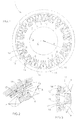
- the rotary electric machine 1 shown in FIG. 1 comprises an inner stator 2 and an outer rotor 3 rotatable about an axis of rotation X.
- the stator 2 comprises a plurality of teeth 4, for example eighteen, on which respective coils 5 are arranged, the stator 2 being for example concentrated winding.
- the teeth 4 are devoid of polar expansion.
- the coils 5 are for example made apart and engaged after their manufacture on the teeth 4.
- the stator 2 can comprise unrepresented cleats closing the notches 6 receiving the coils 5.
- the teeth 4 are connected, in this example, to an annular yoke 8.
- the teeth 4 and the yoke 8 are for example formed of a stack of varnished magnetic sheets. Each sheet has for example as many notches and teeth as the stator. Alternatively, the teeth 4 are carried by assembled sectors.
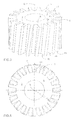
- the teeth 4 are preferably inclined, as illustrated in FIGS. 5 and 6.
- the teeth have first axial ends 4a which are angularly offset relative to opposite second axial ends 4b, relative to the axis of rotation X.
- the offset ⁇ is for example 2 ⁇ / 3P, where P denotes the number of rotor poles.
- this value can be increased up to ⁇ / S, where S denotes the number of stator slots, in the case where ⁇ / S is greater than 2 ⁇ / 3P .
- the inclination of the teeth 4 of the stator further improves the reduction of the torque oscillations in the absence of polar expansions.
- the teeth 4 have end faces 10 which are convex toward the rotor 3. These end faces have, for example, a cylindrical portion, a generatrix parallel to the X axis and of radius of curvature less than the distance d between the X axis and the vertex of the teeth 4.
- the radius of curvature is for example 0.5 to 0.7 times this distance d.
- Rotor 3 rotates on non-visible bearings.
- the rotor 3 comprises a ring-shaped armature 12 having a radially inner surface 13 on which permanent magnets 14, for example sixteen in number, are fixed.
- the armature 12 is for example formed by a stack of varnished magnetic sheets.
- the radially inner surface 13 is for example cylindrical with an X-axis revolution and the magnets 14 have an inner face 16 which is a cylinder portion, being adapted to conform substantially to the shape of the radially inner surface 13 of the armature 12.
- the magnets are for example glued by their face 16 on the frame 12.
- the cylindrical surface 16 of the magnets makes it possible to have a relatively large bonding surface and therefore a good mechanical strength.
- each magnet 14 has an outer face 17 directed towards the stator, which is flat.
- the outer faces 17 of the magnets 14 are perpendicular to the spokes which pass through the X axis and which cut the magnets 14 at mid-length.
- the magnets 14 are monolithic but it is not beyond the scope of the present invention if the magnets 14 are fragmented, for example to reduce the induced current losses.
- the magnetization direction of the magnets 14 is substantially radial, and the polarities of the magnets 14 alternate in the circumferential direction.
- the longitudinal dimension L of the magnets is for example between 1.5 and 2.5 times the width l of the teeth 4.
- the variation of the thickness of the air gap between the end faces 10 and the outer faces 17 makes it possible to benefit from a relatively high torque while reducing the torque ripples.
- the drive of one or more elevator cables can be done without gearing, at least one pulley groove being formed for example on the outer rotor or the latter being coupled to a pulley.
- the rotor may drive a pulley through a gearbox having a relatively low reduction ratio, for example from 1 to 4.
- the nominal speed of rotation is for example between 48 and 355 revolutions per minute.
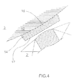
- the rotor 3 may also be an inner rotor, as illustrated in FIG. 4.
- each magnet 14 has an outer face 17 facing towards the stator which is substantially flat and perpendicular to a radius passing through the axis of the rotor and cutting the magnet halfway.
- the magnets 14 may have an inner face 16 opposite the stator which is concave, adapted to match the shape of the armature 12 of the rotor.
- the rotor may for example comprise a number of different poles, as well as for the teeth of the stator.
- the machine can be used not only in motor but also in generator, to perform energy recovery, for example.
- the machine can find applications other than elevator car driving.
Landscapes
- Engineering & Computer Science (AREA)
- Power Engineering (AREA)
- Iron Core Of Rotating Electric Machines (AREA)
- Permanent Magnet Type Synchronous Machine (AREA)
- Permanent Field Magnets Of Synchronous Machinery (AREA)
- Cage And Drive Apparatuses For Elevators (AREA)
Applications Claiming Priority (1)
| Application Number | Priority Date | Filing Date | Title |
|---|---|---|---|
| FR0553707A FR2894403A1 (fr) | 2005-12-02 | 2005-12-02 | Machine electrique tournante a ondulations de couple reduites |
Publications (1)
| Publication Number | Publication Date |
|---|---|
| EP1793482A1 true EP1793482A1 (fr) | 2007-06-06 |
Family
ID=36719211
Family Applications (1)
| Application Number | Title | Priority Date | Filing Date |
|---|---|---|---|
| EP06301180A Withdrawn EP1793482A1 (fr) | 2005-12-02 | 2006-11-24 | Machine électrique tournante à ondulations de couple réduites |
Country Status (5)
| Country | Link |
|---|---|
| US (1) | US7692354B2 (enExample) |
| EP (1) | EP1793482A1 (enExample) |
| JP (1) | JP2007159394A (enExample) |
| CN (1) | CN1976169B (enExample) |
| FR (1) | FR2894403A1 (enExample) |
Cited By (2)
| Publication number | Priority date | Publication date | Assignee | Title |
|---|---|---|---|---|
| WO2018229065A1 (fr) | 2017-06-15 | 2018-12-20 | Moteurs Leroy-Somer | Machine electrique tournante |
| EP4113796A1 (fr) | 2021-07-02 | 2023-01-04 | Moteurs Leroy-Somer | Machine electrique tournante |
Families Citing this family (10)
| Publication number | Priority date | Publication date | Assignee | Title |
|---|---|---|---|---|
| JP5221219B2 (ja) * | 2008-06-20 | 2013-06-26 | 株式会社日立産機システム | 永久磁石式同期モータ |
| GB0902390D0 (en) * | 2009-02-13 | 2009-04-01 | Isis Innovation | Electric machine - flux |
| FR2945388B1 (fr) * | 2009-05-11 | 2013-04-12 | Moving Magnet Technologies M M T | Moteur electrique triphase a faible couple de detente |
| CN102111044B (zh) * | 2009-12-28 | 2013-03-06 | 上海永大吉亿电机有限公司 | 电梯的电机结构及其定子组件 |
| IT1400343B1 (it) * | 2010-05-27 | 2013-05-24 | Idm Srl | Gruppo elettrogeno, particolarmente per caricabatterie. |
| KR101124077B1 (ko) * | 2010-07-21 | 2012-03-20 | 삼성전기주식회사 | 스테이터 코어 및 이를 포함하는 모터 장치 |
| CN104092320A (zh) * | 2014-05-21 | 2014-10-08 | 太仓东元微电机有限公司 | 一种错位黏磁的电机转子 |
| WO2016044925A1 (en) * | 2014-09-24 | 2016-03-31 | Tm4 Inc. | Reluctance assisted external rotor pmsm |
| CN212323825U (zh) * | 2020-01-07 | 2021-01-08 | 上海舞肌科技有限公司 | 永磁无刷电机及机器人关节、伺服舵机执行器、机器人 |
| CN114221468B (zh) * | 2021-12-16 | 2025-10-14 | 武汉天腾动力科技有限公司 | 定子总成、轮毂电机及电动车 |
Citations (12)
| Publication number | Priority date | Publication date | Assignee | Title |
|---|---|---|---|---|
| JPH02184253A (ja) * | 1988-09-12 | 1990-07-18 | Daikin Ind Ltd | 電動機 |
| US5138213A (en) | 1989-12-13 | 1992-08-11 | U.S. Philips Corporation | Brushless d.c. motor |
| JPH07308057A (ja) | 1994-05-11 | 1995-11-21 | Yaskawa Electric Corp | 永久磁石形同期電動機 |
| JPH08275476A (ja) | 1995-03-30 | 1996-10-18 | Hitachi Ltd | 外転型永久磁石回転電機及び外転型永久磁石回転電機を用いた電動車両 |
| JPH10164777A (ja) * | 1996-11-26 | 1998-06-19 | Matsushita Electric Ind Co Ltd | モータ |
| EP0982425A2 (de) * | 1998-08-17 | 2000-03-01 | Miele & Cie. GmbH & Co. | Wäschebehandlungsgerät |
| GB2345586A (en) | 1999-01-11 | 2000-07-12 | Elliott Ind Ltd | An electric motor, a wheel and drive apparatus for an electric vehicle |
| EP1104077A2 (en) | 1999-11-19 | 2001-05-30 | Honda Giken Kogyo Kabushiki Kaisha | Permanent magnet rotary electric motor |
| FR2802724A1 (fr) | 1999-12-15 | 2001-06-22 | Leroy Somer | Stator a dents convexes |
| WO2003052901A1 (en) | 2001-12-14 | 2003-06-26 | Kabushiki Kaisha Toshiba | Permanent magnet type motor and elevator device |
| EP1349261A2 (fr) | 2002-03-25 | 2003-10-01 | Nork 2, S.l. | Moteur compact pour ascenseur |
| US20040140725A1 (en) | 2003-01-16 | 2004-07-22 | Kabushiki Kaisha Moric | Rotary electrical apparatus |
Family Cites Families (13)
| Publication number | Priority date | Publication date | Assignee | Title |
|---|---|---|---|---|
| US2312101A (en) * | 1941-05-28 | 1943-02-23 | Gen Electric | Dynamoelectric machine |
| US4491769A (en) * | 1982-05-24 | 1985-01-01 | Heidelberg Goetz | Rotary electric machine |
| NZ221822A (en) * | 1987-09-15 | 1990-02-26 | Clark Automotive Dev | Permanent magnet motor |
| NL8801700A (nl) * | 1988-07-05 | 1990-02-01 | Philips Nv | Electrische meerpolige machine. |
| TW434972B (en) * | 1998-05-15 | 2001-05-16 | Delta Electronics Inc | Improved method of motor stator |
| JP2000232762A (ja) * | 1999-02-10 | 2000-08-22 | Toshiba Kyaria Kk | 圧縮機用ブラシレスdcモータ及びその駆動制御装置 |
| JP3599616B2 (ja) * | 1999-10-15 | 2004-12-08 | 株式会社日立製作所 | 巻上機用電動機 |
| JP2001119869A (ja) * | 1999-10-20 | 2001-04-27 | Seiko Instruments Inc | モータ用コイルヨーク、モータ、及び回転体装置 |
| JP3691345B2 (ja) * | 2000-05-25 | 2005-09-07 | 三菱電機株式会社 | 永久磁石型電動機 |
| JP3797122B2 (ja) * | 2001-03-09 | 2006-07-12 | 株式会社日立製作所 | 永久磁石式回転電機 |
| JP4942259B2 (ja) * | 2001-07-11 | 2012-05-30 | パナソニック株式会社 | 電動機 |
| JP2004015880A (ja) * | 2002-06-05 | 2004-01-15 | Hitachi Ltd | 永久磁石式同期モータ並びにそれを用いるエレベータ装置 |
| JP2004104986A (ja) * | 2002-07-16 | 2004-04-02 | Japan Servo Co Ltd | 永久磁石形回転電機 |
-
2005
- 2005-12-02 FR FR0553707A patent/FR2894403A1/fr not_active Withdrawn
-
2006
- 2006-11-08 US US11/594,057 patent/US7692354B2/en not_active Expired - Fee Related
- 2006-11-24 EP EP06301180A patent/EP1793482A1/fr not_active Withdrawn
- 2006-12-01 CN CN2006101636664A patent/CN1976169B/zh not_active Expired - Fee Related
- 2006-12-04 JP JP2006327039A patent/JP2007159394A/ja active Pending
Patent Citations (12)
| Publication number | Priority date | Publication date | Assignee | Title |
|---|---|---|---|---|
| JPH02184253A (ja) * | 1988-09-12 | 1990-07-18 | Daikin Ind Ltd | 電動機 |
| US5138213A (en) | 1989-12-13 | 1992-08-11 | U.S. Philips Corporation | Brushless d.c. motor |
| JPH07308057A (ja) | 1994-05-11 | 1995-11-21 | Yaskawa Electric Corp | 永久磁石形同期電動機 |
| JPH08275476A (ja) | 1995-03-30 | 1996-10-18 | Hitachi Ltd | 外転型永久磁石回転電機及び外転型永久磁石回転電機を用いた電動車両 |
| JPH10164777A (ja) * | 1996-11-26 | 1998-06-19 | Matsushita Electric Ind Co Ltd | モータ |
| EP0982425A2 (de) * | 1998-08-17 | 2000-03-01 | Miele & Cie. GmbH & Co. | Wäschebehandlungsgerät |
| GB2345586A (en) | 1999-01-11 | 2000-07-12 | Elliott Ind Ltd | An electric motor, a wheel and drive apparatus for an electric vehicle |
| EP1104077A2 (en) | 1999-11-19 | 2001-05-30 | Honda Giken Kogyo Kabushiki Kaisha | Permanent magnet rotary electric motor |
| FR2802724A1 (fr) | 1999-12-15 | 2001-06-22 | Leroy Somer | Stator a dents convexes |
| WO2003052901A1 (en) | 2001-12-14 | 2003-06-26 | Kabushiki Kaisha Toshiba | Permanent magnet type motor and elevator device |
| EP1349261A2 (fr) | 2002-03-25 | 2003-10-01 | Nork 2, S.l. | Moteur compact pour ascenseur |
| US20040140725A1 (en) | 2003-01-16 | 2004-07-22 | Kabushiki Kaisha Moric | Rotary electrical apparatus |
Non-Patent Citations (2)
| Title |
|---|
| PATENT ABSTRACTS OF JAPAN vol. 1996, no. 03 29 March 1996 (1996-03-29) * |
| PATENT ABSTRACTS OF JAPAN vol. 1998, no. 11 30 September 1998 (1998-09-30) * |
Cited By (4)
| Publication number | Priority date | Publication date | Assignee | Title |
|---|---|---|---|---|
| WO2018229065A1 (fr) | 2017-06-15 | 2018-12-20 | Moteurs Leroy-Somer | Machine electrique tournante |
| US11735967B2 (en) | 2017-06-15 | 2023-08-22 | Moteurs Leroy-Somer | Rotary electric machine with rotor having permanent magnets with concave faces between two flat portions |
| EP4113796A1 (fr) | 2021-07-02 | 2023-01-04 | Moteurs Leroy-Somer | Machine electrique tournante |
| FR3124902A1 (fr) | 2021-07-02 | 2023-01-06 | Moteurs Leroy-Somer | Machine électrique tournante |
Also Published As
| Publication number | Publication date |
|---|---|
| FR2894403A1 (fr) | 2007-06-08 |
| US7692354B2 (en) | 2010-04-06 |
| JP2007159394A (ja) | 2007-06-21 |
| CN1976169B (zh) | 2011-01-19 |
| US20070126308A1 (en) | 2007-06-07 |
| CN1976169A (zh) | 2007-06-06 |
Similar Documents
| Publication | Publication Date | Title |
|---|---|---|
| EP2896114B2 (fr) | Rotor de machine électrique tournante, comportant une masse rotorique dans laquelle sont ménagés des logements | |
| EP1793482A1 (fr) | Machine électrique tournante à ondulations de couple réduites | |
| WO2012164519A1 (fr) | Rotor a aimants permanents et machine tournante comportant un tel rotor | |
| FR2924282A1 (fr) | Procede de fabrication de machine electrique tournante et machine electrique tournante | |
| FR2991118A1 (fr) | Rotor de machine electrique et dispositif de maintien d'aimants permanents associe | |
| EP3639349B1 (fr) | Machine electrique tournante | |
| EP3387742B1 (fr) | Rotor d'un moteur électromagnétique à flux axial à aimant monobloc de forme ondulée | |
| EP1251023B1 (fr) | Machine électrique à rotor extérieur | |
| EP4113796A1 (fr) | Machine electrique tournante | |
| EP2023469A2 (fr) | Générateur électrique et installation comportant une tour d'éclairage alimentée par un tel générateur | |
| WO2024028133A1 (fr) | Machine electrique de traction a flux axial | |
| EP2781007A2 (fr) | Rotor a aimants permanents pour une machine electrique tournante | |
| EP3107193B1 (fr) | Rotor à tôles empilées | |
| WO2016146909A1 (fr) | Rotor de machine electrique tournante a configuration d'aimants permanents optimisee | |
| EP1796248B1 (fr) | Procédé de fabrication d'un rotor et rotor de machine tournante électrique | |
| EP1113564B1 (fr) | Machine électrique tournante dont le stator et/ou le rotor comporte des évidements périphériques | |
| WO2021099023A1 (fr) | Rotor pour machine électrique tournante | |
| WO2020043966A1 (fr) | Procede d'equilibrage d'un rotor de moteur electrique avec usinage du paquet de toles | |
| FR2915033A1 (fr) | Machine electrique tournante a fort couple et double stator | |
| EP2529471A1 (fr) | Rotor a aimants permanents | |
| WO2019206830A1 (fr) | Rotor de machine electrique tournante | |
| WO2021123528A1 (fr) | Rotor de machine electrique tournante | |
| WO2017093636A1 (fr) | Rotor a griffes de machine electrique tournante muni de griffes a chanfrein de forme courbe | |
| FR3156608A1 (fr) | Rotor de machine électrique tournante | |
| WO2021064315A1 (fr) | Rotor de machine electrique tournante |
Legal Events
| Date | Code | Title | Description |
|---|---|---|---|
| PUAI | Public reference made under article 153(3) epc to a published international application that has entered the european phase |
Free format text: ORIGINAL CODE: 0009012 |
|
| AK | Designated contracting states |
Kind code of ref document: A1 Designated state(s): AT BE BG CH CY CZ DE DK EE ES FI FR GB GR HU IE IS IT LI LT LU LV MC NL PL PT RO SE SI SK TR |
|
| AX | Request for extension of the european patent |
Extension state: AL BA HR MK YU |
|
| 17P | Request for examination filed |
Effective date: 20071109 |
|
| 17Q | First examination report despatched |
Effective date: 20071219 |
|
| AKX | Designation fees paid |
Designated state(s): AT BE BG CH CY CZ DE DK EE ES FI FR GB GR HU IE IS IT LI LT LU LV MC NL PL PT RO SE SI SK TR |
|
| RAP3 | Party data changed (applicant data changed or rights of an application transferred) |
Owner name: MOTEURS LEROY-SOMER |
|
| STAA | Information on the status of an ep patent application or granted ep patent |
Free format text: STATUS: THE APPLICATION IS DEEMED TO BE WITHDRAWN |
|
| 18D | Application deemed to be withdrawn |
Effective date: 20130603 |