EP1793480A2 - Flywheel electric generator - Google Patents
Flywheel electric generator Download PDFInfo
- Publication number
- EP1793480A2 EP1793480A2 EP06012751A EP06012751A EP1793480A2 EP 1793480 A2 EP1793480 A2 EP 1793480A2 EP 06012751 A EP06012751 A EP 06012751A EP 06012751 A EP06012751 A EP 06012751A EP 1793480 A2 EP1793480 A2 EP 1793480A2
- Authority
- EP
- European Patent Office
- Prior art keywords
- flywheel
- electric generator
- rotary shaft
- permanent magnets
- motor
- Prior art date
- Legal status (The legal status is an assumption and is not a legal conclusion. Google has not performed a legal analysis and makes no representation as to the accuracy of the status listed.)
- Withdrawn
Links
- 230000008878 coupling Effects 0.000 claims abstract description 5
- 238000010168 coupling process Methods 0.000 claims abstract description 5
- 238000005859 coupling reaction Methods 0.000 claims abstract description 5
- 230000005540 biological transmission Effects 0.000 description 6
- 230000008901 benefit Effects 0.000 description 3
- 238000006243 chemical reaction Methods 0.000 description 3
- 239000002887 superconductor Substances 0.000 description 3
- 230000005284 excitation Effects 0.000 description 2
- 238000005259 measurement Methods 0.000 description 2
- 238000000034 method Methods 0.000 description 2
- 238000010586 diagram Methods 0.000 description 1
- 238000004146 energy storage Methods 0.000 description 1
- 230000004927 fusion Effects 0.000 description 1
- 230000003455 independent Effects 0.000 description 1
- 238000007689 inspection Methods 0.000 description 1
- 238000012423 maintenance Methods 0.000 description 1
- 230000004048 modification Effects 0.000 description 1
- 238000012986 modification Methods 0.000 description 1
- 230000002093 peripheral effect Effects 0.000 description 1
- 238000010248 power generation Methods 0.000 description 1
Images


Classifications
-
- H—ELECTRICITY
- H02—GENERATION; CONVERSION OR DISTRIBUTION OF ELECTRIC POWER
- H02K—DYNAMO-ELECTRIC MACHINES
- H02K53/00—Alleged dynamo-electric perpetua mobilia
-
- H—ELECTRICITY
- H02—GENERATION; CONVERSION OR DISTRIBUTION OF ELECTRIC POWER
- H02K—DYNAMO-ELECTRIC MACHINES
- H02K7/00—Arrangements for handling mechanical energy structurally associated with dynamo-electric machines, e.g. structural association with mechanical driving motors or auxiliary dynamo-electric machines
- H02K7/02—Additional mass for increasing inertia, e.g. flywheels
- H02K7/025—Additional mass for increasing inertia, e.g. flywheels for power storage
-
- F—MECHANICAL ENGINEERING; LIGHTING; HEATING; WEAPONS; BLASTING
- F16—ENGINEERING ELEMENTS AND UNITS; GENERAL MEASURES FOR PRODUCING AND MAINTAINING EFFECTIVE FUNCTIONING OF MACHINES OR INSTALLATIONS; THERMAL INSULATION IN GENERAL
- F16H—GEARING
- F16H33/00—Gearings based on repeated accumulation and delivery of energy
- F16H33/02—Rotary transmissions with mechanical accumulators, e.g. weights, springs, intermittently-connected flywheels
-
- H—ELECTRICITY
- H02—GENERATION; CONVERSION OR DISTRIBUTION OF ELECTRIC POWER
- H02K—DYNAMO-ELECTRIC MACHINES
- H02K21/00—Synchronous motors having permanent magnets; Synchronous generators having permanent magnets
- H02K21/12—Synchronous motors having permanent magnets; Synchronous generators having permanent magnets with stationary armatures and rotating magnets
- H02K21/14—Synchronous motors having permanent magnets; Synchronous generators having permanent magnets with stationary armatures and rotating magnets with magnets rotating within the armatures
-
- Y—GENERAL TAGGING OF NEW TECHNOLOGICAL DEVELOPMENTS; GENERAL TAGGING OF CROSS-SECTIONAL TECHNOLOGIES SPANNING OVER SEVERAL SECTIONS OF THE IPC; TECHNICAL SUBJECTS COVERED BY FORMER USPC CROSS-REFERENCE ART COLLECTIONS [XRACs] AND DIGESTS
- Y02—TECHNOLOGIES OR APPLICATIONS FOR MITIGATION OR ADAPTATION AGAINST CLIMATE CHANGE
- Y02E—REDUCTION OF GREENHOUSE GAS [GHG] EMISSIONS, RELATED TO ENERGY GENERATION, TRANSMISSION OR DISTRIBUTION
- Y02E60/00—Enabling technologies; Technologies with a potential or indirect contribution to GHG emissions mitigation
- Y02E60/16—Mechanical energy storage, e.g. flywheels or pressurised fluids
Definitions
- the flywheel electric generator is an electric generator to discharge kinetic energy stored in the flywheel coupled to a rotor of the electric generator, as electric power. That is, the flywheel electric generator employs a system by which electric energy is converted into rotational energy of an object having large inertia moment to store it. In general, the flywheel electric generator is often utilized to supply electric power to a load in need of pulse-like large electric power.
- a nuclear fusion system confining plasma by means of a magnetic field supplies electric power of several hundreds of thousands kw in a short time such as several seconds sometimes, so that it is disagreeable to directly obtain such pulse-like electric power from a electric power system because the influence on the power system is too considerable. Therefore, such a field of the electric power system employs the flywheel electric generator.
- the flywheel electric generator operates in such a cycle that it increases the number of rotations of an electric generator over a time interval of several minutes to store the kinetic energy in the flywheel, and discharges the kinetic energy stored in the flywheel in supplying the electric power to a load to result in a decrease in the number of the rotations of the electric generator.
- a conventional flywheel electric generator directly couples an electric motor for driving to an electric generator.
- An output from the electric generator independents from the electric power system and the flywheel electric generator also varies the number of rotations of the electric generator with the power supply to the load, so that a frequency also varies in synchronization with the number of rotations thereof.
- FIG. 7 shows a configuration view of a control device of such conventional flywheel electric generator.
- a flywheel electric generator 51 is driven by an electric motor for driving 52 to store the kinetic energy in the flywheel electric generator 51.
- the electric motor 52 is connected to a receiving-power-end bus-bar 53 of the electric power system through a breaker 54a and controlled by a Scherbius device 55 on the basis of the number of rotations from a means 56 for detecting the number of rotations.
- the Scherbius device 55 conducts secondary exciting control of the electric motor 52 to regenerate a part of secondary electric power generated on a secondary side to the bus-bar 53 through a breaker 54b.
- the electric generator 51 To supply the electric power from the flywheel electric generator 51 to a load 57, the electric generator 51 is excited by an exciting device 58 to generate the electric power and supplies it to the load 57 to decrease the number of its own rotations.
- the electric generator 51 supplies an excitation power source to the exciting device 58 from the bus-bar 53 through a breaker 54c (refer to, for instance, Japanese Patent Application KOKAI Publication No. 2001-258294 ).
- a technique using a magnetic shaft composed of a levitating magnet and a levitating bulk made of a high-temperature superconductor positioned facing the levitating magnet in a sealed container and operating the flywheel electric generator by setting surrounding atmospheric pressure of the rotor in the sealed container to a range within 0.1 atm to 0.4 atm is disclosed (refer to, for instance, Japan Patent Application KOKAI Publication No. 6-303738 ).
- the technique in which the magnetic shaft composed of the levitating magnet and the levitating bulk made of the high-temperature superconductor positioned facing the levitating magnet is used in the sealed container, needs a large-scaled device for operating the high-temperature superconductor sufficiently.
- the system for housing the flywheel electric generator in the sealed container is not preferable because the whole of the system becomes complex and large and the system takes a great deal of time in working maintenance and inspection and in re-starting thereafter.
- a flywheel electric generator includes a start-up motor; a flywheel rotary shaft which is rotated by the start-up motor; a flywheel which rotates by coupling with the flywheel rotary shaft; a plurality of permanent magnets which are disposed at a substantially equal distance on outer circumferential sections of the flywheel; a pair of electromagnets arranged at fixed positions on both sides of the flywheel along its diameter direction so as to face the permanent magnets; and an electric generator which is rotationally driven by the flywheel rotary shaft.
- the flywheel is composed of two pieces of circular plates which are arranged separately in parallel to each other and a plurality of support plates which are disposed so as to couple the two pieces of the circular plates with one another on circumferential sections thereof, and the plurality of permanent magnets are supported on the plurality of the support plates, respectively.
- the flywheel rotary shaft is coupled with the start-up motor and the electric generator, respectively, through a first and a second clutches.
- the inclination angle is not more than 30° each.
- the inclination angle is approximately 22.5° each.
- the first and second clutches are electromagnetic clutches.
- the permanent magnets of an even number are arranged on the outer circumferential sections of the flywheel.
- a minimum gap between the facing surfaces of the electromagnets and the permanent magnets is 1 mm.
- FIG. 1 is an exemplary side elevation view showing a schematic configuration of a flywheel electric generator regarding an embodiment of the present invention
- FIG. 2 is its exemplary plan view.
- a flywheel electric generator 1 of the embodiment includes three stages of angle structures 2, 3 and 4 which are arranged at each position of an upper stage, a middle stage and a lower stage in a vertical direction, respectively.
- the upper stage angle structure 2 is formed, as shown in FIG. 2, of three arms 2a which are coupled so that they form a planar shape of a triangle.
- An upper stage bearing 5 is supported with three arms 2a through three bearing support arms 5a at the central part of the upper stage angle structure 2.
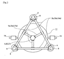
- the middle stage angle structure 3 is also has the approximately same structure as that of the upper angle structure 2. That is, the middle stage angel structure 3 is formed, as partly shown in FIG. 3, of three arms 3a which are coupled with one another so that its planar shape becomes a triangle.
- a middle stage bearing 6 is supported by the three arms 3a through three bearing support arms 6a at the central part of the middle stage angel structure 3.
- the lower stage angel structure 4 is also has the approximately same structure as that of the upper angle structure 2. That is, the lower stage angel structure 4 is also formed, as a partly shown in FIG. 3, of three arms 4a which are coupled with one another so that its planner shape becomes a triangle.
- a lower stage bearing 7 is supported by the three arms 4a through three bearing support arms 7a at the central part of the lower stage angle structure 4.
- the tops of the angle structures 2, 3 and 4 are fixed with three fixing poles 8 formed in a vertically elected state on leg bases 9, respectively, and the angle structures 2. 3 and 4 of the three stages are integrally coupled with one another.
- the flywheel 11 is fixed to a flywheel rotary shaft 11a pivoted by an upper stage bearing 5 disposed at the upper stage angle structure 2 and by a middle stage bearing 6 disposed at the middle stage angle structure 3 by use of a hub 12.
- the rotary shaft 11a is extended downward from the middle stage bearing 6 and its lower end is coupled with a first electromagnetic clutch 13.
- the first electromagnetic clutch 13 is also coupled with a first pulley rotary shaft 14a.
- the flywheel rotary shaft 11a and the first pulley rotary shaft 14a are coupled or separated in accordance with opening/closing of the first electromagnetic clutch 13, and as a result, electric power is transmitted or shut off.
- the first pulley 14 is coupled with a start-up motor 16 fixed on the lower surface of the middle stage angel structure 3 through a transmission belt 15.
- the start-up motor 16 is, for example, a two-pole motor of 2.2 kw using an inverter and its number of rotations is 3,400 rpm.
- the flywheel 11 is a basket-shaped rotor in which two metallic circular plates 11b are supported in parallel to each other with a plurality of sheets of iron-made support plates 17.
- the support plates 17 are formed, for instance, by 18 sheets thereof and arranged at substantially an equal angular space of around 20° on the peripheral edges of each circular plate 11b.
- Each plate-like permanent magnet 18 is fixed on a surface of the sheet at an approximately central section in a vertical direction of each support plate 17.
- FIG. 3 is the horizontal cross sectional view of the flywheel 11 shown in FIG. 1.
- each plate surface of the support plates 17 is not perpendicular to each radius direction of the flywheel 11 and arranged with an inclination thereto.
- Each plate surface of the plate-like permanent magnets 18 fixed on each plate surface of the support plates 17 is also arranged with an inclination to the radius direction.
- the inclination angle is around 67.5° at the cross angle between the radius direction of the flywheel 11 and the plate surface of the permanent magnet 18, and around 22.5° at the cross angle between a tangent direction of a circle forming the outer circumference of the flywheel 11 and the plate surface of the permanent magnet 18.
- a pair of electromagnets 19 is arranged at fixed positions on both sides of the flywheel 11 along its diameter direction so as to face the permanent magnet 18.
- FIG. 5 is a partly enlarged view showing a positional relationship between the permanent magnet 18 fixed to the outer circumferential section of the flywheel 11 and the electromagnet 19 disposed to face the permanent magnet 18.
- the permanent magnet 18 has a shape of which the horizontal cross sectional shape is a rectangular with a long side 18a and a short side 18b, and each corner 18c at which the sides 18a and 18b are crossed is arranged on an outer circumferential edge C of the flywheel 11.
- the rotating direction of the flywheel 11 is indicated by an arrow A.
- the long side 18a is arranged with an inclination so as to be closer to a central side rather than the outer circumferential edge C toward the rotating direction.
- the inclination angle is experimentally confirmed that the above-described angle is preferable therefor.
- the pair of electromagnets 19 is disposed at positions facing the permanent magnets 18 which are fixed on the outer circumferential sections of the flywheel 11 with prescribed gaps.
- the electromagnets 19 are respectively disposed, as shown in FIG. 3, on the opposite sides on a diameter line (not shown) crossing the flywheel 11.
- the pair of electromagnets 19 is supported with fixing poles 18 fixing the angle structures 2, 3 and 4 at the circumferences of the flywheel 11.
- each of the permanent magnet 18 and the electromagnet 19 form a magnetic circuit for a motor.
- the magnet 18 forms a rotor
- the pair of electromagnets 19 forms a stator
- the supplying a pulse signal to the pair of electromagnets 19 forms a stepping motor (pulse motor).
- the stepping motor drives the flywheel 11, for instance, at a time when the number of rotations is 400 rpm.
- a break disk 21 operating as a disk break is fixed to the first pulley rotary shaft 14a, and a second electromagnetic clutch 22 is coupled to the lower end of the rotary shaft 14a.
- the opposed end of the second electromagnetic clutch 22 is fixed to a pulley rotary shaft 23a of which the lower end is pivoted by a lower stage bearing 7.
- a second pulley 23 is fixed to the second pulley rotary shaft 23a.
- a transmission belt 25 couples the second pulley 23 with an electric generator pulley 27 fixed to a rotary shaft of an electric generator 26.
- the electric generator 26 rotating in accordance with the rotation of the electric generator pulley 27 has, for instance, a rated power of 7.5 kw, an AC frequency of 30 Hz and the number of rotations of 600 rpm.
- the electric generator 26 closes the first clutch 13 to star-up the rotation of the start-up motor 16 in a state with the second clutch 22 opened therein, then, transmits its torque to the first pulley rotary shaft 14a through the transmission belt 15 and the first pulley 14 to rotate it.
- the first clutch 13 having closed, the first pulley rotary shaft 14a and the flywheel rotary shaft 11a are coupled with each other.
- the rotation of the first pulley rotary shaft 14a is thereby transmitted to the flywheel rotary shaft 11a to rotate it and further rotate the flywheel 11 fixed to the flywheel rotary shaft 11a.
- Step 2 Flywheel rotation step
- FIG. 4 is a graph showing a result of measurement of relationships between relative positions of the permanent magnets 18 against the electromagnets 19 disposed on the flywheel 11 and the torque (knockout force).
- each plate face of the permanent magnet 18 is disposed in a state in which it is not inclined to the radius direction of the flywheel 11 but orthogonal thereto and each opposing gap between the permanent magnet 18 and the electromagnet 19 in the radius direction is kept at 1 mm.
- the lateral axis of FIG. 4 indicates the distance (mm) between the permanent magnet 18 and electromagnet 19 in the rotating direction of the flywheel 11 in a range of 0 to 20 mm, and the longitudinal axis indicates the torque (kg) at the stepping motor.
- each plate surface of the permanent magnet 18 is inclined to the radius direction of the flywheel 11, and the pulse currents are applied at the timing right after the permanent magnet 18 has passes through the position opposite to the electromagnet 19 by the rotation of the flywheel 11.
- the electric generator 26 can continuously operate the torque also to the side 18b of the permanent magnet 18 after operating the torque to the side 18a of the outer circumferential side of the permanent magnet 18. The operation results in enabling the electric generator 26 to apply a strong knockout force to the permanent magnet 18. This fact is also confirmed experimentally.
- the flywheel 11 After the rotating speed of the flywheel 11 has reached a sufficient speed, even when the electric generator 26 stops applying the pulse currents to the electromagnet 19, the flywheel 11 keeps the rotations by itself over a prescribed time interval by inertia.
- Step 3 Power generation step
- the electric generator 26 brings both first and second clutches 13 and 22 into closed states.
- the operations of two clutches 13 and 22 produce coupling among the flywheel rotary shaft 11a, the first pulley rotary shaft 14a and the second pulley rotary shaft 23a with one another.
- the coupling results in the transmission of the rotations of the flywheel 11 to the second pulley rotary shaft 23a through the flywheel rotary shaft 11a and the first pulley rotary shaft 14a to make the second pulley rotary shaft 23a rotate.
- the rotations of the second pulley rotary shaft 23a makes the second pulley 23 rotate and further makes the electric generator pulley 27 rotate through the transmission belt 25.
- the electric generator pulley 27 being fixed to the rotary shaft of the electric generator 26, the electric generator 26 generates the electric power.
- the electric generator 26 can be stopped by operating the break disk 21.
- the torque (TF) of the flywheel rotary shaft 11a becomes the sum of the torque (TA) from the start-up motor 16 and the torque (TB) from the stepping motor formed on the outer circumferential section of the flywheel 11.
- the torque (TF), (TA) and (TB) will be explained in turn.
Landscapes
- Engineering & Computer Science (AREA)
- Power Engineering (AREA)
- General Engineering & Computer Science (AREA)
- Mechanical Engineering (AREA)
- Connection Of Motors, Electrical Generators, Mechanical Devices, And The Like (AREA)
Abstract
Description
- This application is based upon and claims the benefit of priority from the prior
Japanese Patent Application No. 2005-346002, filed on November 30, 2005 - The present invention relates to a flywheel electric generator utilizing rotational kinetic energy of a flywheel.
- The flywheel electric generator is an electric generator to discharge kinetic energy stored in the flywheel coupled to a rotor of the electric generator, as electric power. That is, the flywheel electric generator employs a system by which electric energy is converted into rotational energy of an object having large inertia moment to store it. In general, the flywheel electric generator is often utilized to supply electric power to a load in need of pulse-like large electric power.
- For instance, a nuclear fusion system confining plasma by means of a magnetic field supplies electric power of several hundreds of thousands kw in a short time such as several seconds sometimes, so that it is disagreeable to directly obtain such pulse-like electric power from a electric power system because the influence on the power system is too considerable. Therefore, such a field of the electric power system employs the flywheel electric generator. The flywheel electric generator operates in such a cycle that it increases the number of rotations of an electric generator over a time interval of several minutes to store the kinetic energy in the flywheel, and discharges the kinetic energy stored in the flywheel in supplying the electric power to a load to result in a decrease in the number of the rotations of the electric generator.
- Usually, a conventional flywheel electric generator directly couples an electric motor for driving to an electric generator. An output from the electric generator independents from the electric power system and the flywheel electric generator also varies the number of rotations of the electric generator with the power supply to the load, so that a frequency also varies in synchronization with the number of rotations thereof.
- FIG. 7 shows a configuration view of a control device of such conventional flywheel electric generator. A flywheel
electric generator 51 is driven by an electric motor for driving 52 to store the kinetic energy in the flywheelelectric generator 51. Theelectric motor 52 is connected to a receiving-power-end bus-bar 53 of the electric power system through abreaker 54a and controlled by a Scherbiusdevice 55 on the basis of the number of rotations from ameans 56 for detecting the number of rotations. The Scherbiusdevice 55 conducts secondary exciting control of theelectric motor 52 to regenerate a part of secondary electric power generated on a secondary side to the bus-bar 53 through abreaker 54b. - To supply the electric power from the flywheel
electric generator 51 to aload 57, theelectric generator 51 is excited by anexciting device 58 to generate the electric power and supplies it to theload 57 to decrease the number of its own rotations. Theelectric generator 51 supplies an excitation power source to theexciting device 58 from the bus-bar 53 through abreaker 54c (refer to, for instance,Japanese Patent Application KOKAI Publication No. 2001-258294 - With respect to a structure of a fly wheel electric generator, in a conventional flywheel electric generator, other than one, in which a flywheel is attached to a usual salient pole type electric generator to operate it by using a usual bearing in the atmosphere, a technique using a magnetic shaft composed of a levitating magnet and a levitating bulk made of a high-temperature superconductor positioned facing the levitating magnet in a sealed container and operating the flywheel electric generator by setting surrounding atmospheric pressure of the rotor in the sealed container to a range within 0.1 atm to 0.4 atm is disclosed (refer to, for instance,
Japan Patent Application KOKAI Publication No. 6-303738 - In such a conventional flywheel electric generator, the heavier the weight of the flywheel becomes, the larger an energy storage quantity becomes and, on the other hand, the larger a mechanical loss at the bearing, etc., becomes. Therefore, in the case of use of a usual bearing for the flywheel electric generator, a requirement for a large output causes a large mechanical loss at the bearing and certainly causes a reduction in efficiency as the flywheel electric generator.
- As disclosed in the latter patent document given above, the technique, in which the magnetic shaft composed of the levitating magnet and the levitating bulk made of the high-temperature superconductor positioned facing the levitating magnet is used in the sealed container, needs a large-scaled device for operating the high-temperature superconductor sufficiently.
- As mentioned above, the system for housing the flywheel electric generator in the sealed container is not preferable because the whole of the system becomes complex and large and the system takes a great deal of time in working maintenance and inspection and in re-starting thereafter.
- The present invention is invented on the basis of the foregoing situation, and an object of the invention is to provide a flywheel electric generator capable of obtaining an output with efficiency even in the atmosphere.
- A flywheel electric generator according to an embodiment of the present invention includes a start-up motor; a flywheel rotary shaft which is rotated by the start-up motor; a flywheel which rotates by coupling with the flywheel rotary shaft; a plurality of permanent magnets which are disposed at a substantially equal distance on outer circumferential sections of the flywheel; a pair of electromagnets arranged at fixed positions on both sides of the flywheel along its diameter direction so as to face the permanent magnets; and an electric generator which is rotationally driven by the flywheel rotary shaft.
- In the flywheel electric generator described above, the flywheel is composed of two pieces of circular plates which are arranged separately in parallel to each other and a plurality of support plates which are disposed so as to couple the two pieces of the circular plates with one another on circumferential sections thereof, and the plurality of permanent magnets are supported on the plurality of the support plates, respectively.
- Further, in the flywheel electric generator, the flywheel rotary shaft is coupled with the start-up motor and the electric generator, respectively, through a first and a second clutches.
- Further, in the flywheel electric generator, the facing surfaces of the permanent magnets and the electromagnets are arranged at prescribed inclination angle.
- Further, in the flywheel electric generator, the inclination angle is not more than 30° each.
- Further, in the flywheel electric generator, the inclination angle is approximately 22.5° each.
- Further, in the flywheel electric generator, the first and second clutches are electromagnetic clutches.
- Further, in the flywheel electric generator, the permanent magnets of an even number are arranged on the outer circumferential sections of the flywheel.
- And further, in the flywheel electric generator, a minimum gap between the facing surfaces of the electromagnets and the permanent magnets is 1 mm.
- Additional objects and advantages of the invention will be set forth in the description which follows, and in part will be obvious from the description, or may be learned by practice of the invention. The objects and advantages of the invention may be realized and obtained by means of the instrumentalities and combinations particularly pointed out hereinafter.
- The accompanying drawings, which are incorporated in and constitute a part of the specification, illustrate embodiments of the invention, and together with the general description given above and the detailed description of the embodiments given below, serve to explain the principles of the invention.
- FIG. 1 is an exemplary schematic side elevation view showing an embodiment of a flywheel electric generator of the present invention;
- FIG. 2 is an exemplary schematic horizontal plan view of the flywheel electric generator shown in FIG. 1;
- FIG. 3 is an exemplary horizontal cross sectional view of the flywheel shown in FIG. 1;
- FIG. 4 is an exemplary graph indicating measured torque of a stepping motor shown in FIG. 3;
- FIG. 5 is an exemplary partly enlarged view of the stepping motor shown in FIG. 3;
- FIG. 6 is an exemplary explanatory view used for calculating torque in operating the flywheel electric generator; and
- FIG. 7 is an exemplary block diagram showing an example of use of a conventional flywheel electric generator.
- Hereinafter, embodiments of the present invention will be described with reference to the drawings in detail. FIG. 1 is an exemplary side elevation view showing a schematic configuration of a flywheel electric generator regarding an embodiment of the present invention, and FIG. 2 is its exemplary plan view.
- A flywheel
electric generator 1 of the embodiment includes three stages ofangle structures stage angle structure 2 is formed, as shown in FIG. 2, of threearms 2a which are coupled so that they form a planar shape of a triangle. An upper stage bearing 5 is supported with threearms 2a through threebearing support arms 5a at the central part of the upperstage angle structure 2. The middlestage angle structure 3 is also has the approximately same structure as that of theupper angle structure 2. That is, the middlestage angel structure 3 is formed, as partly shown in FIG. 3, of threearms 3a which are coupled with one another so that its planar shape becomes a triangle. A middle stage bearing 6 is supported by the threearms 3a through three bearingsupport arms 6a at the central part of the middlestage angel structure 3. The lowerstage angel structure 4 is also has the approximately same structure as that of theupper angle structure 2. That is, the lowerstage angel structure 4 is also formed, as a partly shown in FIG. 3, of threearms 4a which are coupled with one another so that its planner shape becomes a triangle. A lower stage bearing 7 is supported by the threearms 4a through threebearing support arms 7a at the central part of the lowerstage angle structure 4. - The tops of the
angle structures fixing poles 8 formed in a vertically elected state onleg bases 9, respectively, and theangle structures 2. 3 and 4 of the three stages are integrally coupled with one another. - The
flywheel 11 is fixed to a flywheelrotary shaft 11a pivoted by an upper stage bearing 5 disposed at the upperstage angle structure 2 and by a middle stage bearing 6 disposed at the middlestage angle structure 3 by use of ahub 12. Therotary shaft 11a is extended downward from the middle stage bearing 6 and its lower end is coupled with a first electromagnetic clutch 13. The first electromagnetic clutch 13 is also coupled with a first pulleyrotary shaft 14a. Thus, the flywheelrotary shaft 11a and the first pulleyrotary shaft 14a are coupled or separated in accordance with opening/closing of the first electromagnetic clutch 13, and as a result, electric power is transmitted or shut off. - The
first pulley 14 is coupled with a start-up motor 16 fixed on the lower surface of the middlestage angel structure 3 through atransmission belt 15. Thetransmission belt 15, accordingly, transmits the electric power from the start-up motor 16 to thefirst pulley 14. The start-upmotor 16 is, for example, a two-pole motor of 2.2 kw using an inverter and its number of rotations is 3,400 rpm. - The
flywheel 11 is a basket-shaped rotor in which two metalliccircular plates 11b are supported in parallel to each other with a plurality of sheets of iron-madesupport plates 17. Here, thesupport plates 17 are formed, for instance, by 18 sheets thereof and arranged at substantially an equal angular space of around 20° on the peripheral edges of eachcircular plate 11b. Each plate-likepermanent magnet 18 is fixed on a surface of the sheet at an approximately central section in a vertical direction of eachsupport plate 17. - FIG. 3 is the horizontal cross sectional view of the
flywheel 11 shown in FIG. 1. As shown in FIG. 3, each plate surface of thesupport plates 17 is not perpendicular to each radius direction of theflywheel 11 and arranged with an inclination thereto. Each plate surface of the plate-likepermanent magnets 18 fixed on each plate surface of thesupport plates 17 is also arranged with an inclination to the radius direction. The inclination angle is around 67.5° at the cross angle between the radius direction of theflywheel 11 and the plate surface of thepermanent magnet 18, and around 22.5° at the cross angle between a tangent direction of a circle forming the outer circumference of theflywheel 11 and the plate surface of thepermanent magnet 18. - A pair of
electromagnets 19 is arranged at fixed positions on both sides of theflywheel 11 along its diameter direction so as to face thepermanent magnet 18. - FIG. 5 is a partly enlarged view showing a positional relationship between the
permanent magnet 18 fixed to the outer circumferential section of theflywheel 11 and theelectromagnet 19 disposed to face thepermanent magnet 18. Thepermanent magnet 18 has a shape of which the horizontal cross sectional shape is a rectangular with along side 18a and ashort side 18b, and eachcorner 18c at which thesides flywheel 11. Here, the rotating direction of theflywheel 11 is indicated by an arrow A. Thelong side 18a is arranged with an inclination so as to be closer to a central side rather than the outer circumferential edge C toward the rotating direction. The inclination angle is experimentally confirmed that the above-described angle is preferable therefor. - On the other hand, the pair of
electromagnets 19 is disposed at positions facing thepermanent magnets 18 which are fixed on the outer circumferential sections of theflywheel 11 with prescribed gaps. Theelectromagnets 19 are respectively disposed, as shown in FIG. 3, on the opposite sides on a diameter line (not shown) crossing theflywheel 11. Not shown in the figure, the pair ofelectromagnets 19 is supported with fixingpoles 18 fixing theangle structures flywheel 11. - With the arrangement given above, each of the
permanent magnet 18 and theelectromagnet 19 form a magnetic circuit for a motor. In other words, themagnet 18 forms a rotor, the pair ofelectromagnets 19 forms a stator, and the supplying a pulse signal to the pair ofelectromagnets 19 forms a stepping motor (pulse motor). The stepping motor drives theflywheel 11, for instance, at a time when the number of rotations is 400 rpm. - In the lower section of the
first pulley 14, abreak disk 21 operating as a disk break is fixed to the firstpulley rotary shaft 14a, and a secondelectromagnetic clutch 22 is coupled to the lower end of therotary shaft 14a. The opposed end of the secondelectromagnetic clutch 22 is fixed to apulley rotary shaft 23a of which the lower end is pivoted by alower stage bearing 7. Asecond pulley 23 is fixed to the secondpulley rotary shaft 23a. Atransmission belt 25 couples thesecond pulley 23 with anelectric generator pulley 27 fixed to a rotary shaft of anelectric generator 26. Theelectric generator 26 rotating in accordance with the rotation of theelectric generator pulley 27 has, for instance, a rated power of 7.5 kw, an AC frequency of 30 Hz and the number of rotations of 600 rpm. - Next to this, operations of the
electric generator 26 having theflywheel 11 configured as mentioned above will be described by dividing them into three steps. - The
electric generator 26 closes the first clutch 13 to star-up the rotation of the start-upmotor 16 in a state with the second clutch 22 opened therein, then, transmits its torque to the firstpulley rotary shaft 14a through thetransmission belt 15 and thefirst pulley 14 to rotate it. At this moment, the first clutch 13 having closed, the firstpulley rotary shaft 14a and theflywheel rotary shaft 11a are coupled with each other. The rotation of the firstpulley rotary shaft 14a is thereby transmitted to theflywheel rotary shaft 11a to rotate it and further rotate theflywheel 11 fixed to theflywheel rotary shaft 11a. - After starting up the rotation of the
flywheel 11, theelectric generator 26 opens the first clutch 13 to disconnect theflywheel rotary shaft 11a from therotary shaft 14a of thefirst pulley 14. In this state, the pair ofelectromagnets 19 is supplied with pulse currents by a pulse signal generator, which is not shown in the drawings. The pulse currents are applied at timing right after eachpermanent magnet 18 has passed through the position facing eachelectromagnet 19 by the rotations of theflywheel 11. As the result of the excitation caused by the pulse signals from theelectromagnets 19, repulsive force generated between theelectromagnets 19 and thepermanent magnets 18 further applies torque to theflywheel 11 in the rotating direction thereof. - FIG. 4 is a graph showing a result of measurement of relationships between relative positions of the
permanent magnets 18 against theelectromagnets 19 disposed on theflywheel 11 and the torque (knockout force). During the measurement, each plate face of thepermanent magnet 18 is disposed in a state in which it is not inclined to the radius direction of theflywheel 11 but orthogonal thereto and each opposing gap between thepermanent magnet 18 and theelectromagnet 19 in the radius direction is kept at 1 mm. The lateral axis of FIG. 4 indicates the distance (mm) between thepermanent magnet 18 andelectromagnet 19 in the rotating direction of theflywheel 11 in a range of 0 to 20 mm, and the longitudinal axis indicates the torque (kg) at the stepping motor. - As cleared from FIG. 4, the torque of the stepping motor reaches a maximum value of around 8 kg when the distance between the
permanent magnet 18 and theelectromagnet 19 in the rotating direction is around 8 mm. The maximum torque is generated as pulling force when the distance between thepermanent magnet 18 and theelectromagnet 19 becomes 8 mm before thepermanent magnet 18 passes through the position facing the electromagnet 19 (entrance side), and as reaction force when the distance between thepermanent magnet 18 and theelectromagnet 19 becomes 8 mm after thepermanent magnet 18 passes through the position facing the electromagnet 19 (exit side). In the embodiment of the invention, however, as shown in FIG. 5, each plate surface of thepermanent magnet 18 is inclined to the radius direction of theflywheel 11, and the pulse currents are applied at the timing right after thepermanent magnet 18 has passes through the position opposite to theelectromagnet 19 by the rotation of theflywheel 11. In other words, if the pulse currents for theelectromagnet 19 are applied at the exit side, theelectric generator 26 can continuously operate the torque also to theside 18b of thepermanent magnet 18 after operating the torque to theside 18a of the outer circumferential side of thepermanent magnet 18. The operation results in enabling theelectric generator 26 to apply a strong knockout force to thepermanent magnet 18. This fact is also confirmed experimentally. - After the rotating speed of the
flywheel 11 has reached a sufficient speed, even when theelectric generator 26 stops applying the pulse currents to theelectromagnet 19, theflywheel 11 keeps the rotations by itself over a prescribed time interval by inertia. - When the
flywheel 11 reaches the prescribed number of rotations, theelectric generator 26 brings both first andsecond clutches 13 and 22 into closed states. The operations of twoclutches 13 and 22 produce coupling among theflywheel rotary shaft 11a, the firstpulley rotary shaft 14a and the secondpulley rotary shaft 23a with one another. The coupling results in the transmission of the rotations of theflywheel 11 to the secondpulley rotary shaft 23a through theflywheel rotary shaft 11a and the firstpulley rotary shaft 14a to make the secondpulley rotary shaft 23a rotate. The rotations of the secondpulley rotary shaft 23a makes thesecond pulley 23 rotate and further makes theelectric generator pulley 27 rotate through thetransmission belt 25. Theelectric generator pulley 27 being fixed to the rotary shaft of theelectric generator 26, theelectric generator 26 generates the electric power. Theelectric generator 26 can be stopped by operating thebreak disk 21. - Successively, the torque acting on the
flywheel rotary shaft 11a in operating the flywheelelectric generator 1 will be described by referring to the explanatory view of the flywheel electric generator of the present invention shown in FIG. 6. In FIG. 6, twoclutches 13 and 22 are in a state of closing in generating the electric power. Thus, each of therotary shafts clutches 13 and 22 are omitted from FIG. 6. - The torque (TF) of the
flywheel rotary shaft 11a becomes the sum of the torque (TA) from the start-upmotor 16 and the torque (TB) from the stepping motor formed on the outer circumferential section of theflywheel 11. Hereinafter, the torque (TF), (TA) and (TB) will be explained in turn. - The following
Formula 1 is satisfied for the relationship among the torque (TF), (TA) and (TB) where the number of rotations of the start-upmotor 16 is N (rpm), a torque is T (Nm) and rated electric power is H (kw).
- With modification of
Formula 1, the followingFormula 2 is satisfied where unit conversions are 1 kg = 9.80 Nm, and NM = 0.101972 kg · m.
- The
Formula 2 is modified as follows: where the output from the start-upmotor 16 is 2.2 kw and the number of rotations offlywheel rotary shaft 11a is 400 rpm
- With performing a unit conversion from Nm into kg, the following formula is satisfied.

- Therefore, the torque TA from the start-up
motor 16 of theflywheel rotary shaft 11a becomes 5.36 kg · m. - Since the diameter of the
flywheel 11 is 1.5 m, the torque (knockout force) by the repulsive force from thepermanent magnet 18 and theelectromagnet 19 to theflywheel 11 is 8 kg, and theelectromagnets 19 are disposed at two spots, respectively, the torque TB from the stepping motor is expressed as follows:
- Accordingly, the torque (TF) from the
flywheel rotary shaft 11a is expressed as follows:
- Next, in a calculation of the torque (TG) of the
electric generator 26 by the torque (TF) of theflywheel rotary shaft 11a, because the number of the rotations of theelectric generator 26 is 600 rpm, the torque (TG) is obtained as follow:
- On the other hand, performing a single calculation of the torque (TH) of the rotary shaft of the
electric generator 26 by use ofFormula 2, because the output from theelectric generator 26 is 67 kw and the number of rotations thereof is 600 rpm, the torque (TH) is obtained as follows:
- Here, comparing the torque (TG) of the rotary shaft of the
electric generator 26 obtained from the torque (TF) of theflywheel rotary shaft 11a to the torque (TH) singly calculated by use ofFormula 2, the relationship between the torques (TG) and (TH) is expressed as follows:
- That is to say, the
flywheel 11 applies, to theelectric generator 26, torque not smaller than the rated power of theelectric generator 26. Consequently, it has become obvious that the flywheelelectric generator 1 can increase the generated electric power which is output from theelectric generator 26. - The present invention is not limited to the specific details and representative embodiments shown and described herein, this invention may be modified in various forms without departing from the sprit or scope of the general inventive concept thereof.
- It is explicitly stated that all features disclosed in the description and/or the claims are intended to be disclosed separately and independently from each other for the purpose of original disclosure as well as for the purpose of restricting the claimed invention independent of the composition of the features in the embodiments and/or the claims. It is explicitly stated that all value ranges or indications of groups of entities disclose every possible intermediate value or intermediate entity for the purpose of original disclosure as well as for the purpose of restricting the claimed invention, in particular as limits of value ranges.
Claims (9)
- A flywheel electric generator, comprising:a start-up motor;a flywheel rotary shaft which is rotated by the start-up motor;a flywheel which rotates by coupling with the flywheel rotary shaft;a plurality of permanent magnets which are disposed at a substantially equal distance on outer circumferential sections of the flywheel;a pair of electromagnets arranged at fixed positions on both sides of the flywheel along its diameter direction so as to face the permanent magnets; andan electric generator which is rotationally driven by the flywheel rotary shaft.
- The flywheel electric generator according to claim 1, wherein
the flywheel is composed of two pieces of circular plates which are arranged separately in parallel to each other and a plurality of support plates which are disposed so as to couple the two pieces of the circular plates with one another on circumferential sections thereof, and
the plurality of permanent magnets are supported on the plurality of the support plates, respectively. - The flywheel electric generator according to claim 1 or 2, wherein the flywheel rotary shaft is coupled with the start-up motor and the electric generator, respectively, through a first and a second clutches.
- The flywheel electric generator according to any of claims 1 to 3, wherein the facing surfaces of the permanent magnets and the electromagnets are arranged with a prescribed inclination angle.
- The flywheel electric generator according to claim 4, wherein the inclination angle is not more than 30°each.
- The flywheel electric generator according to claim 5, wherein the inclination angle is approximately 22.5°each.
- The flywheel electric generator according to claim 3 and any of claims 4 to 6, wherein the first and second clutches are electromagnetic clutches.
- The flywheel electric generator according to any of claims 1 to 7, wherein the permanent magnets of an even number are arranged on the outer circumferential sections of the flywheel.
- The flywheel electric generator according to any of claims 1 to 8, wherein a minimum gap between the facing positions of the electromagnets and the permanent magnets is approximately 1 mm.
Applications Claiming Priority (1)
| Application Number | Priority Date | Filing Date | Title |
|---|---|---|---|
| JP2005346002A JP4914060B2 (en) | 2005-11-30 | 2005-11-30 | Flywheel generator |
Publications (2)
| Publication Number | Publication Date |
|---|---|
| EP1793480A2 true EP1793480A2 (en) | 2007-06-06 |
| EP1793480A3 EP1793480A3 (en) | 2008-12-24 |
Family
ID=37882447
Family Applications (1)
| Application Number | Title | Priority Date | Filing Date |
|---|---|---|---|
| EP06012751A Withdrawn EP1793480A3 (en) | 2005-11-30 | 2006-06-21 | Flywheel electric generator |
Country Status (5)
| Country | Link |
|---|---|
| US (1) | US20070120430A1 (en) |
| EP (1) | EP1793480A3 (en) |
| JP (1) | JP4914060B2 (en) |
| KR (1) | KR100805011B1 (en) |
| CN (1) | CN100472095C (en) |
Cited By (8)
| Publication number | Priority date | Publication date | Assignee | Title |
|---|---|---|---|---|
| EP1950871A2 (en) | 2007-01-26 | 2008-07-30 | Value Supplier & Developer Corporation | Flywheel electric generator |
| WO2010140012A1 (en) * | 2009-06-05 | 2010-12-09 | Seper, Gyula | Ecological mechanical force-generating magnetic mill |
| WO2011091493A1 (en) * | 2010-01-28 | 2011-08-04 | Cavalheiro Mario Teixeira | Hydraulic power generator with a circular movement for generating electric energy at two different generation points and mechanic power generator with a circular movement for generating electric energy |
| EP2752579A4 (en) * | 2011-09-02 | 2015-06-24 | Napone Co Ltd | ROTATION ASSISTANCE DEVICE, ROTATION ASSISTANCE METHOD, AND POWER GENERATING DEVICE |
| EP3182561A1 (en) * | 2016-11-03 | 2017-06-21 | Jie Neng Power Industry Co., Ltd. | Electricity generation device with low power consumption |
| US10122240B2 (en) | 2016-10-27 | 2018-11-06 | Jie Neng Power Industry Co., Ltd. | Electricity generation device with low power consumption |
| CZ308739B6 (en) * | 2020-02-05 | 2021-04-14 | Petr Orel | Magnetic turbine and assembly of magnetic turbines |
| EP4098865A1 (en) | 2021-06-06 | 2022-12-07 | Magdy Maher Eskander Salib | A self-powered electric generator that works by circulating water in a closed circuit |
Families Citing this family (25)
| Publication number | Priority date | Publication date | Assignee | Title |
|---|---|---|---|---|
| DE102007030055B4 (en) * | 2007-06-29 | 2010-01-28 | Enocean Gmbh | Energy converter, counter with energy converter, device with counter, method for converting mechanical into electrical energy, and counting method |
| RU2377458C2 (en) * | 2008-02-12 | 2009-12-27 | Пермоторс ГмбХ | Operation method of power rotation drive and power plant for its implementation |
| EP2274818A1 (en) * | 2008-04-07 | 2011-01-19 | Energiestro | Energy storage device comprising a flywheel |
| US20090309363A1 (en) * | 2008-06-12 | 2009-12-17 | Salvatore Rocco Uglietto | Electric wheel |
| CN101667762B (en) * | 2008-09-02 | 2011-12-07 | 福建宇力高新能源开发有限公司 | double-flywheel battery |
| US20100283266A1 (en) * | 2009-05-06 | 2010-11-11 | Averox North America Inc. | Magnetic field powered electrical generating system |
| WO2011013139A1 (en) * | 2009-07-28 | 2011-02-03 | Pramod Kumar Nanda | Auto power plant |
| JP4926263B2 (en) * | 2010-06-07 | 2012-05-09 | 株式会社 杉原産業 | Flywheel and power generator |
| US8766500B2 (en) | 2010-07-28 | 2014-07-01 | James M. Porter, SR. | System and method for power purifying |
| US8104560B1 (en) * | 2010-11-12 | 2012-01-31 | Ting-Jung Tseng | Driving device utilizing inertia |
| US20120200090A1 (en) * | 2011-02-07 | 2012-08-09 | Ezra Shimshi | Energy source system and method |
| CN102340209B (en) * | 2011-09-23 | 2013-08-28 | 三人集团有限公司 | Permanent-magnet flywheel type motor |
| TWI478468B (en) * | 2013-01-28 | 2015-03-21 | Jun Dong Power Corp | Power generator |
| KR101459020B1 (en) * | 2013-11-12 | 2014-11-07 | 주식회사 씨피이셀 | System for Flywheel Energy Storage using a surplus electric energy |
| KR101604637B1 (en) * | 2014-08-18 | 2016-03-21 | 안종석 | Vaccum motor with generator |
| WO2016195467A1 (en) * | 2015-06-03 | 2016-12-08 | Castro Gonzalez José Guillermo | Gravity motor |
| CN106678306A (en) * | 2015-11-09 | 2017-05-17 | 熵零股份有限公司 | Energy adjusting method and energy adjusting system applying energy adjusting method |
| EP3649727A4 (en) | 2017-07-03 | 2021-03-24 | Clean Powr Pty Ltd. | ENERGY PRODUCTION EQUIPMENT |
| CN111779643A (en) * | 2020-07-15 | 2020-10-16 | 杜桂生 | Steel bridge-shaped road automobile wheel pressure gravity power generation system |
| US20220329144A1 (en) * | 2021-04-07 | 2022-10-13 | Ransey Harvey | Self-Contained Electric Energy Generator System |
| WO2022220796A1 (en) | 2021-04-13 | 2022-10-20 | Cummins Inc. | Electrical machines with separately integrated starter ring gear and transmission coupler |
| KR102793835B1 (en) * | 2021-11-22 | 2025-04-11 | 한국전력공사 | Clutch type synchronous phase modifier using flywheel and driving control method for clutch type synchronous condenser using the same |
| CN114050687A (en) * | 2021-11-26 | 2022-02-15 | 北京丰润铭科贸有限责任公司 | A self-excited high-efficiency counter-rotating power generation system |
| KR102449428B1 (en) * | 2021-12-31 | 2022-09-30 | 조출규 | Flywheel power plant and power generation system including same |
| IL298179B2 (en) * | 2022-11-13 | 2024-08-01 | Peter Graner | peripherals expending chambers flywheel engine powered forms by compressed air hydrogen production water steam production energies storage and supplies |
Family Cites Families (20)
| Publication number | Priority date | Publication date | Assignee | Title |
|---|---|---|---|---|
| JPS62171458A (en) * | 1986-01-24 | 1987-07-28 | Kohei Minato | Magnetic force rotating apparatus |
| JP2852157B2 (en) * | 1992-05-12 | 1999-01-27 | 株式会社日立製作所 | Flywheel generator |
| US5731645A (en) * | 1996-02-05 | 1998-03-24 | Magnetic Bearing Technologies, Inc. | Integrated motor/generator/flywheel utilizing a solid steel rotor |
| DE19608099C1 (en) * | 1996-03-02 | 1997-02-27 | Karlsruhe Forschzent | Flywheel energy store |
| ES2123442B1 (en) * | 1996-12-11 | 1999-09-16 | Lopez Berastegui Pedro | MAGNET DRIVEN TORQUE MULTIPLIER. |
| US6387007B1 (en) * | 1997-01-24 | 2002-05-14 | Anthony W. Fini, Jr. | Electromechanical vehicle regeneration system |
| JPH10248206A (en) * | 1997-03-03 | 1998-09-14 | Isuzu Ceramics Kenkyusho:Kk | Cogeneration device with multiple generators |
| JP2002005004A (en) | 2000-06-16 | 2002-01-09 | Yoshikatsu Abe | Energy converting equipment |
| WO2002073788A1 (en) * | 2001-03-14 | 2002-09-19 | Akira Hosaka | Magnetic motor |
| KR100429914B1 (en) * | 2002-01-09 | 2004-05-03 | 학교법인 포항공과대학교 | Emergency generating system using flywheel |
| JP2003204663A (en) * | 2002-01-09 | 2003-07-18 | Aidekku Kk | Rotating apparatus |
| JP2003219581A (en) | 2002-01-24 | 2003-07-31 | Railway Technical Res Inst | Superconducting flywheel power storage device |
| US6750588B1 (en) * | 2002-06-03 | 2004-06-15 | Christopher W. Gabrys | High performance axial gap alternator motor |
| US6844647B2 (en) * | 2002-08-27 | 2005-01-18 | Seiberco Incorporated | Permanent magnet motor having flux density characteristics that are internally variable |
| US7233088B2 (en) * | 2003-01-17 | 2007-06-19 | Magnetic Torque International, Ltd. | Torque converter and system using the same |
| US6967417B2 (en) * | 2003-01-29 | 2005-11-22 | Miekka Fred N | Variable winding generator |
| JP2005098213A (en) * | 2003-09-25 | 2005-04-14 | Jiro Komori | Power generating device |
| JP2005245079A (en) * | 2004-02-25 | 2005-09-08 | Kohei Minato | Magnetism rotation-type motor-generator |
| JP4542473B2 (en) * | 2005-06-30 | 2010-09-15 | 株式会社カワサキプレシジョンマシナリ | Valve plate and hydraulic device including the same |
| JP2008187758A (en) * | 2007-01-26 | 2008-08-14 | Vsd:Kk | Flywheel generator |
-
2005
- 2005-11-30 JP JP2005346002A patent/JP4914060B2/en not_active Expired - Fee Related
-
2006
- 2006-06-21 EP EP06012751A patent/EP1793480A3/en not_active Withdrawn
- 2006-06-26 US US11/474,466 patent/US20070120430A1/en not_active Abandoned
- 2006-06-29 KR KR1020060059112A patent/KR100805011B1/en not_active Expired - Fee Related
- 2006-06-29 CN CNB2006100956699A patent/CN100472095C/en not_active Expired - Fee Related
Cited By (10)
| Publication number | Priority date | Publication date | Assignee | Title |
|---|---|---|---|---|
| EP1950871A2 (en) | 2007-01-26 | 2008-07-30 | Value Supplier & Developer Corporation | Flywheel electric generator |
| EP1950871A3 (en) * | 2007-01-26 | 2009-01-14 | Value Supplier & Developer Corporation | Flywheel electric generator |
| US7541783B2 (en) | 2007-01-26 | 2009-06-02 | Value Supplier & Developer Corporation | Flywheel electric generator |
| WO2010140012A1 (en) * | 2009-06-05 | 2010-12-09 | Seper, Gyula | Ecological mechanical force-generating magnetic mill |
| WO2011091493A1 (en) * | 2010-01-28 | 2011-08-04 | Cavalheiro Mario Teixeira | Hydraulic power generator with a circular movement for generating electric energy at two different generation points and mechanic power generator with a circular movement for generating electric energy |
| EP2752579A4 (en) * | 2011-09-02 | 2015-06-24 | Napone Co Ltd | ROTATION ASSISTANCE DEVICE, ROTATION ASSISTANCE METHOD, AND POWER GENERATING DEVICE |
| US10122240B2 (en) | 2016-10-27 | 2018-11-06 | Jie Neng Power Industry Co., Ltd. | Electricity generation device with low power consumption |
| EP3182561A1 (en) * | 2016-11-03 | 2017-06-21 | Jie Neng Power Industry Co., Ltd. | Electricity generation device with low power consumption |
| CZ308739B6 (en) * | 2020-02-05 | 2021-04-14 | Petr Orel | Magnetic turbine and assembly of magnetic turbines |
| EP4098865A1 (en) | 2021-06-06 | 2022-12-07 | Magdy Maher Eskander Salib | A self-powered electric generator that works by circulating water in a closed circuit |
Also Published As
| Publication number | Publication date |
|---|---|
| EP1793480A3 (en) | 2008-12-24 |
| CN100472095C (en) | 2009-03-25 |
| JP2007151364A (en) | 2007-06-14 |
| KR20070056912A (en) | 2007-06-04 |
| US20070120430A1 (en) | 2007-05-31 |
| CN1975204A (en) | 2007-06-06 |
| JP4914060B2 (en) | 2012-04-11 |
| KR100805011B1 (en) | 2008-02-20 |
Similar Documents
| Publication | Publication Date | Title |
|---|---|---|
| EP1793480A2 (en) | Flywheel electric generator | |
| JP2008187758A (en) | Flywheel generator | |
| US7385328B2 (en) | Cogging reduction in permanent magnet machines | |
| US10148159B2 (en) | Magnetic rotating apparatus, electric motor, and motor generator | |
| EP2081276A1 (en) | Electro-magnetical device with reversible generator-motor operation | |
| US20130049512A1 (en) | Axial flux permanent magnet synchronous generator and motor | |
| CN100387833C (en) | power generation device | |
| KR20090033866A (en) | Polyphase multi coil generator | |
| JP2007503199A (en) | Electric motor having a permanent magnet rotor | |
| EP2605373A2 (en) | Motor | |
| JPH0681555B2 (en) | Variable speed generator and method | |
| Lee et al. | Newly structured double excited two-degree-of-freedom motor for security camera | |
| EP2587639A2 (en) | Lamination stack for an electrical machine stator | |
| KR20020083700A (en) | A motive not strength dynamo | |
| AU2020202450A1 (en) | Combined Motor Stator | |
| WO2004111498A1 (en) | High efficiency torque converter | |
| EP4293876A1 (en) | Magnetic geared rotary machine and power generation system | |
| JP2001238429A (en) | Rotary speed-up device | |
| CA1185315A (en) | Electric inching impulse control | |
| US12003200B2 (en) | 4-phase switched reluctance motor | |
| JP2012016244A (en) | Single-phase ac synchronous motor and single-phase dc brushless motor | |
| KR20100019270A (en) | Rotational apparatus using the magnet and generator using the same | |
| NO347834B1 (en) | Multi plate reluctance motor | |
| KR100656157B1 (en) | Brushless dc motor | |
| Vanslette | Torque generation using ferroelectric materials |
Legal Events
| Date | Code | Title | Description |
|---|---|---|---|
| PUAI | Public reference made under article 153(3) epc to a published international application that has entered the european phase |
Free format text: ORIGINAL CODE: 0009012 |
|
| 17P | Request for examination filed |
Effective date: 20060621 |
|
| AK | Designated contracting states |
Kind code of ref document: A2 Designated state(s): AT BE BG CH CY CZ DE DK EE ES FI FR GB GR HU IE IS IT LI LT LU LV MC NL PL PT RO SE SI SK TR |
|
| AX | Request for extension of the european patent |
Extension state: AL BA HR MK YU |
|
| PUAL | Search report despatched |
Free format text: ORIGINAL CODE: 0009013 |
|
| AK | Designated contracting states |
Kind code of ref document: A3 Designated state(s): AT BE BG CH CY CZ DE DK EE ES FI FR GB GR HU IE IS IT LI LT LU LV MC NL PL PT RO SE SI SK TR |
|
| AX | Request for extension of the european patent |
Extension state: AL BA HR MK RS |
|
| RIC1 | Information provided on ipc code assigned before grant |
Ipc: H02K 21/14 20060101ALN20081120BHEP Ipc: H02K 53/00 20060101ALI20081120BHEP Ipc: H02K 7/02 20060101AFI20081120BHEP |
|
| STAA | Information on the status of an ep patent application or granted ep patent |
Free format text: STATUS: THE APPLICATION HAS BEEN WITHDRAWN |
|
| 18W | Application withdrawn |
Effective date: 20090317 |