EP1791480B1 - Bone fixation/fusion device - Google Patents
Bone fixation/fusion device Download PDFInfo
- Publication number
- EP1791480B1 EP1791480B1 EP05782575.4A EP05782575A EP1791480B1 EP 1791480 B1 EP1791480 B1 EP 1791480B1 EP 05782575 A EP05782575 A EP 05782575A EP 1791480 B1 EP1791480 B1 EP 1791480B1
- Authority
- EP
- European Patent Office
- Prior art keywords
- bone
- region
- fixation
- fusion
- bone fixation
- Prior art date
- Legal status (The legal status is an assumption and is not a legal conclusion. Google has not performed a legal analysis and makes no representation as to the accuracy of the status listed.)
- Active
Links
- 210000000988 bone and bone Anatomy 0.000 title claims description 179
- 230000004927 fusion Effects 0.000 title claims description 95
- 239000000463 material Substances 0.000 claims description 14
- 230000006641 stabilisation Effects 0.000 claims description 12
- 238000011105 stabilization Methods 0.000 claims description 12
- 239000002131 composite material Substances 0.000 claims description 9
- 229910052751 metal Inorganic materials 0.000 claims description 8
- 239000002184 metal Substances 0.000 claims description 7
- 229910000684 Cobalt-chrome Inorganic materials 0.000 claims description 3
- 229910001069 Ti alloy Inorganic materials 0.000 claims description 3
- RTAQQCXQSZGOHL-UHFFFAOYSA-N Titanium Chemical compound [Ti] RTAQQCXQSZGOHL-UHFFFAOYSA-N 0.000 claims description 3
- 229910000811 surgical stainless steel Inorganic materials 0.000 claims description 3
- 229910052715 tantalum Inorganic materials 0.000 claims description 3
- GUVRBAGPIYLISA-UHFFFAOYSA-N tantalum atom Chemical compound [Ta] GUVRBAGPIYLISA-UHFFFAOYSA-N 0.000 claims description 3
- 239000010936 titanium Substances 0.000 claims description 3
- 229910052719 titanium Inorganic materials 0.000 claims description 3
- 238000009434 installation Methods 0.000 claims description 2
- 230000000149 penetrating effect Effects 0.000 claims 2
- 208000010392 Bone Fractures Diseases 0.000 description 27
- 206010017076 Fracture Diseases 0.000 description 25
- 238000002513 implantation Methods 0.000 description 6
- 210000003484 anatomy Anatomy 0.000 description 5
- 238000003780 insertion Methods 0.000 description 4
- 230000037431 insertion Effects 0.000 description 4
- 230000000087 stabilizing effect Effects 0.000 description 4
- 239000012620 biological material Substances 0.000 description 3
- 230000000052 comparative effect Effects 0.000 description 3
- 238000007796 conventional method Methods 0.000 description 3
- 238000007499 fusion processing Methods 0.000 description 3
- 238000010079 rubber tapping Methods 0.000 description 3
- 229920000954 Polyglycolide Polymers 0.000 description 2
- 238000010521 absorption reaction Methods 0.000 description 2
- 230000000712 assembly Effects 0.000 description 2
- 238000000429 assembly Methods 0.000 description 2
- 239000000919 ceramic Substances 0.000 description 2
- 239000003795 chemical substances by application Substances 0.000 description 2
- 230000000295 complement effect Effects 0.000 description 2
- 230000008878 coupling Effects 0.000 description 2
- 238000010168 coupling process Methods 0.000 description 2
- 238000005859 coupling reaction Methods 0.000 description 2
- 230000009969 flowable effect Effects 0.000 description 2
- 239000012634 fragment Substances 0.000 description 2
- 230000035876 healing Effects 0.000 description 2
- 239000007943 implant Substances 0.000 description 2
- 238000011065 in-situ storage Methods 0.000 description 2
- 210000001872 metatarsal bone Anatomy 0.000 description 2
- 238000000034 method Methods 0.000 description 2
- 239000004633 polyglycolic acid Substances 0.000 description 2
- 210000001519 tissue Anatomy 0.000 description 2
- 241001440267 Cyclodes Species 0.000 description 1
- 102000010834 Extracellular Matrix Proteins Human genes 0.000 description 1
- 108010037362 Extracellular Matrix Proteins Proteins 0.000 description 1
- 208000006670 Multiple fractures Diseases 0.000 description 1
- 208000002565 Open Fractures Diseases 0.000 description 1
- 239000003522 acrylic cement Substances 0.000 description 1
- 230000001154 acute effect Effects 0.000 description 1
- 230000000845 anti-microbial effect Effects 0.000 description 1
- 230000002785 anti-thrombosis Effects 0.000 description 1
- 239000003146 anticoagulant agent Substances 0.000 description 1
- 230000008901 benefit Effects 0.000 description 1
- 239000000316 bone substitute Substances 0.000 description 1
- 238000000576 coating method Methods 0.000 description 1
- 238000010276 construction Methods 0.000 description 1
- 229920001577 copolymer Polymers 0.000 description 1
- 230000007423 decrease Effects 0.000 description 1
- 238000005553 drilling Methods 0.000 description 1
- -1 e.g. Substances 0.000 description 1
- 210000002744 extracellular matrix Anatomy 0.000 description 1
- 238000001125 extrusion Methods 0.000 description 1
- 239000011521 glass Substances 0.000 description 1
- 238000001727 in vivo Methods 0.000 description 1
- 238000007373 indentation Methods 0.000 description 1
- 210000000859 intermediate cuneiform Anatomy 0.000 description 1
- 238000003754 machining Methods 0.000 description 1
- 230000013011 mating Effects 0.000 description 1
- 239000011159 matrix material Substances 0.000 description 1
- 230000007246 mechanism Effects 0.000 description 1
- 210000000113 medial cuneiform Anatomy 0.000 description 1
- 239000007769 metal material Substances 0.000 description 1
- 238000012986 modification Methods 0.000 description 1
- 230000004048 modification Effects 0.000 description 1
- 238000000465 moulding Methods 0.000 description 1
- 230000000399 orthopedic effect Effects 0.000 description 1
- 230000002138 osteoinductive effect Effects 0.000 description 1
- 239000004626 polylactic acid Substances 0.000 description 1
- 229920000642 polymer Polymers 0.000 description 1
- 239000011148 porous material Substances 0.000 description 1
- 230000008569 process Effects 0.000 description 1
- 230000001737 promoting effect Effects 0.000 description 1
- 210000004872 soft tissue Anatomy 0.000 description 1
- 239000011343 solid material Substances 0.000 description 1
- 238000001356 surgical procedure Methods 0.000 description 1
Images


Classifications
-
- A—HUMAN NECESSITIES
- A61—MEDICAL OR VETERINARY SCIENCE; HYGIENE
- A61B—DIAGNOSIS; SURGERY; IDENTIFICATION
- A61B17/00—Surgical instruments, devices or methods, e.g. tourniquets
- A61B17/56—Surgical instruments or methods for treatment of bones or joints; Devices specially adapted therefor
- A61B17/58—Surgical instruments or methods for treatment of bones or joints; Devices specially adapted therefor for osteosynthesis, e.g. bone plates, screws, setting implements or the like
- A61B17/68—Internal fixation devices, including fasteners and spinal fixators, even if a part thereof projects from the skin
- A61B17/84—Fasteners therefor or fasteners being internal fixation devices
- A61B17/86—Pins or screws or threaded wires; nuts therefor
- A61B17/864—Pins or screws or threaded wires; nuts therefor hollow, e.g. with socket or cannulated
-
- A—HUMAN NECESSITIES
- A61—MEDICAL OR VETERINARY SCIENCE; HYGIENE
- A61B—DIAGNOSIS; SURGERY; IDENTIFICATION
- A61B17/00—Surgical instruments, devices or methods, e.g. tourniquets
- A61B17/16—Bone cutting, breaking or removal means other than saws, e.g. Osteoclasts; Drills or chisels for bones; Trepans
- A61B17/1613—Component parts
- A61B17/1615—Drill bits, i.e. rotating tools extending from a handpiece to contact the worked material
-
- A—HUMAN NECESSITIES
- A61—MEDICAL OR VETERINARY SCIENCE; HYGIENE
- A61B—DIAGNOSIS; SURGERY; IDENTIFICATION
- A61B17/00—Surgical instruments, devices or methods, e.g. tourniquets
- A61B17/56—Surgical instruments or methods for treatment of bones or joints; Devices specially adapted therefor
- A61B17/58—Surgical instruments or methods for treatment of bones or joints; Devices specially adapted therefor for osteosynthesis, e.g. bone plates, screws, setting implements or the like
- A61B17/68—Internal fixation devices, including fasteners and spinal fixators, even if a part thereof projects from the skin
- A61B17/70—Spinal positioners or stabilisers ; Bone stabilisers comprising fluid filler in an implant
-
- A—HUMAN NECESSITIES
- A61—MEDICAL OR VETERINARY SCIENCE; HYGIENE
- A61B—DIAGNOSIS; SURGERY; IDENTIFICATION
- A61B17/00—Surgical instruments, devices or methods, e.g. tourniquets
- A61B17/56—Surgical instruments or methods for treatment of bones or joints; Devices specially adapted therefor
- A61B17/58—Surgical instruments or methods for treatment of bones or joints; Devices specially adapted therefor for osteosynthesis, e.g. bone plates, screws, setting implements or the like
- A61B17/68—Internal fixation devices, including fasteners and spinal fixators, even if a part thereof projects from the skin
- A61B17/84—Fasteners therefor or fasteners being internal fixation devices
- A61B17/846—Nails or pins, i.e. anchors without movable parts, holding by friction only, with or without structured surface
-
- A—HUMAN NECESSITIES
- A61—MEDICAL OR VETERINARY SCIENCE; HYGIENE
- A61B—DIAGNOSIS; SURGERY; IDENTIFICATION
- A61B17/00—Surgical instruments, devices or methods, e.g. tourniquets
- A61B17/56—Surgical instruments or methods for treatment of bones or joints; Devices specially adapted therefor
- A61B17/58—Surgical instruments or methods for treatment of bones or joints; Devices specially adapted therefor for osteosynthesis, e.g. bone plates, screws, setting implements or the like
- A61B17/68—Internal fixation devices, including fasteners and spinal fixators, even if a part thereof projects from the skin
- A61B17/84—Fasteners therefor or fasteners being internal fixation devices
- A61B17/86—Pins or screws or threaded wires; nuts therefor
- A61B17/8625—Shanks, i.e. parts contacting bone tissue
-
- A—HUMAN NECESSITIES
- A61—MEDICAL OR VETERINARY SCIENCE; HYGIENE
- A61B—DIAGNOSIS; SURGERY; IDENTIFICATION
- A61B17/00—Surgical instruments, devices or methods, e.g. tourniquets
- A61B17/56—Surgical instruments or methods for treatment of bones or joints; Devices specially adapted therefor
- A61B17/58—Surgical instruments or methods for treatment of bones or joints; Devices specially adapted therefor for osteosynthesis, e.g. bone plates, screws, setting implements or the like
- A61B17/68—Internal fixation devices, including fasteners and spinal fixators, even if a part thereof projects from the skin
- A61B17/84—Fasteners therefor or fasteners being internal fixation devices
- A61B17/86—Pins or screws or threaded wires; nuts therefor
- A61B17/866—Material or manufacture
-
- A—HUMAN NECESSITIES
- A61—MEDICAL OR VETERINARY SCIENCE; HYGIENE
- A61B—DIAGNOSIS; SURGERY; IDENTIFICATION
- A61B17/00—Surgical instruments, devices or methods, e.g. tourniquets
- A61B17/56—Surgical instruments or methods for treatment of bones or joints; Devices specially adapted therefor
- A61B17/58—Surgical instruments or methods for treatment of bones or joints; Devices specially adapted therefor for osteosynthesis, e.g. bone plates, screws, setting implements or the like
- A61B17/68—Internal fixation devices, including fasteners and spinal fixators, even if a part thereof projects from the skin
- A61B17/84—Fasteners therefor or fasteners being internal fixation devices
- A61B17/86—Pins or screws or threaded wires; nuts therefor
- A61B17/8685—Pins or screws or threaded wires; nuts therefor comprising multiple separate parts
-
- A—HUMAN NECESSITIES
- A61—MEDICAL OR VETERINARY SCIENCE; HYGIENE
- A61F—FILTERS IMPLANTABLE INTO BLOOD VESSELS; PROSTHESES; DEVICES PROVIDING PATENCY TO, OR PREVENTING COLLAPSING OF, TUBULAR STRUCTURES OF THE BODY, e.g. STENTS; ORTHOPAEDIC, NURSING OR CONTRACEPTIVE DEVICES; FOMENTATION; TREATMENT OR PROTECTION OF EYES OR EARS; BANDAGES, DRESSINGS OR ABSORBENT PADS; FIRST-AID KITS
- A61F2/00—Filters implantable into blood vessels; Prostheses, i.e. artificial substitutes or replacements for parts of the body; Appliances for connecting them with the body; Devices providing patency to, or preventing collapsing of, tubular structures of the body, e.g. stents
- A61F2/02—Prostheses implantable into the body
- A61F2/30—Joints
- A61F2/44—Joints for the spine, e.g. vertebrae, spinal discs
- A61F2/4455—Joints for the spine, e.g. vertebrae, spinal discs for the fusion of spinal bodies, e.g. intervertebral fusion of adjacent spinal bodies, e.g. fusion cages
-
- A—HUMAN NECESSITIES
- A61—MEDICAL OR VETERINARY SCIENCE; HYGIENE
- A61F—FILTERS IMPLANTABLE INTO BLOOD VESSELS; PROSTHESES; DEVICES PROVIDING PATENCY TO, OR PREVENTING COLLAPSING OF, TUBULAR STRUCTURES OF THE BODY, e.g. STENTS; ORTHOPAEDIC, NURSING OR CONTRACEPTIVE DEVICES; FOMENTATION; TREATMENT OR PROTECTION OF EYES OR EARS; BANDAGES, DRESSINGS OR ABSORBENT PADS; FIRST-AID KITS
- A61F2/00—Filters implantable into blood vessels; Prostheses, i.e. artificial substitutes or replacements for parts of the body; Appliances for connecting them with the body; Devices providing patency to, or preventing collapsing of, tubular structures of the body, e.g. stents
- A61F2/0077—Special surfaces of prostheses, e.g. for improving ingrowth
-
- A—HUMAN NECESSITIES
- A61—MEDICAL OR VETERINARY SCIENCE; HYGIENE
- A61F—FILTERS IMPLANTABLE INTO BLOOD VESSELS; PROSTHESES; DEVICES PROVIDING PATENCY TO, OR PREVENTING COLLAPSING OF, TUBULAR STRUCTURES OF THE BODY, e.g. STENTS; ORTHOPAEDIC, NURSING OR CONTRACEPTIVE DEVICES; FOMENTATION; TREATMENT OR PROTECTION OF EYES OR EARS; BANDAGES, DRESSINGS OR ABSORBENT PADS; FIRST-AID KITS
- A61F2/00—Filters implantable into blood vessels; Prostheses, i.e. artificial substitutes or replacements for parts of the body; Appliances for connecting them with the body; Devices providing patency to, or preventing collapsing of, tubular structures of the body, e.g. stents
- A61F2/02—Prostheses implantable into the body
- A61F2/28—Bones
-
- A—HUMAN NECESSITIES
- A61—MEDICAL OR VETERINARY SCIENCE; HYGIENE
- A61F—FILTERS IMPLANTABLE INTO BLOOD VESSELS; PROSTHESES; DEVICES PROVIDING PATENCY TO, OR PREVENTING COLLAPSING OF, TUBULAR STRUCTURES OF THE BODY, e.g. STENTS; ORTHOPAEDIC, NURSING OR CONTRACEPTIVE DEVICES; FOMENTATION; TREATMENT OR PROTECTION OF EYES OR EARS; BANDAGES, DRESSINGS OR ABSORBENT PADS; FIRST-AID KITS
- A61F2/00—Filters implantable into blood vessels; Prostheses, i.e. artificial substitutes or replacements for parts of the body; Appliances for connecting them with the body; Devices providing patency to, or preventing collapsing of, tubular structures of the body, e.g. stents
- A61F2/02—Prostheses implantable into the body
- A61F2/30—Joints
- A61F2/30767—Special external or bone-contacting surface, e.g. coating for improving bone ingrowth
-
- A—HUMAN NECESSITIES
- A61—MEDICAL OR VETERINARY SCIENCE; HYGIENE
- A61F—FILTERS IMPLANTABLE INTO BLOOD VESSELS; PROSTHESES; DEVICES PROVIDING PATENCY TO, OR PREVENTING COLLAPSING OF, TUBULAR STRUCTURES OF THE BODY, e.g. STENTS; ORTHOPAEDIC, NURSING OR CONTRACEPTIVE DEVICES; FOMENTATION; TREATMENT OR PROTECTION OF EYES OR EARS; BANDAGES, DRESSINGS OR ABSORBENT PADS; FIRST-AID KITS
- A61F2/00—Filters implantable into blood vessels; Prostheses, i.e. artificial substitutes or replacements for parts of the body; Appliances for connecting them with the body; Devices providing patency to, or preventing collapsing of, tubular structures of the body, e.g. stents
- A61F2/02—Prostheses implantable into the body
- A61F2/30—Joints
- A61F2/44—Joints for the spine, e.g. vertebrae, spinal discs
- A61F2/4455—Joints for the spine, e.g. vertebrae, spinal discs for the fusion of spinal bodies, e.g. intervertebral fusion of adjacent spinal bodies, e.g. fusion cages
- A61F2/4465—Joints for the spine, e.g. vertebrae, spinal discs for the fusion of spinal bodies, e.g. intervertebral fusion of adjacent spinal bodies, e.g. fusion cages having a circular or kidney shaped cross-section substantially perpendicular to the axis of the spine
-
- A—HUMAN NECESSITIES
- A61—MEDICAL OR VETERINARY SCIENCE; HYGIENE
- A61F—FILTERS IMPLANTABLE INTO BLOOD VESSELS; PROSTHESES; DEVICES PROVIDING PATENCY TO, OR PREVENTING COLLAPSING OF, TUBULAR STRUCTURES OF THE BODY, e.g. STENTS; ORTHOPAEDIC, NURSING OR CONTRACEPTIVE DEVICES; FOMENTATION; TREATMENT OR PROTECTION OF EYES OR EARS; BANDAGES, DRESSINGS OR ABSORBENT PADS; FIRST-AID KITS
- A61F2/00—Filters implantable into blood vessels; Prostheses, i.e. artificial substitutes or replacements for parts of the body; Appliances for connecting them with the body; Devices providing patency to, or preventing collapsing of, tubular structures of the body, e.g. stents
- A61F2/02—Prostheses implantable into the body
- A61F2/30—Joints
- A61F2/44—Joints for the spine, e.g. vertebrae, spinal discs
- A61F2/4455—Joints for the spine, e.g. vertebrae, spinal discs for the fusion of spinal bodies, e.g. intervertebral fusion of adjacent spinal bodies, e.g. fusion cages
- A61F2/447—Joints for the spine, e.g. vertebrae, spinal discs for the fusion of spinal bodies, e.g. intervertebral fusion of adjacent spinal bodies, e.g. fusion cages substantially parallelepipedal, e.g. having a rectangular or trapezoidal cross-section
-
- A—HUMAN NECESSITIES
- A61—MEDICAL OR VETERINARY SCIENCE; HYGIENE
- A61F—FILTERS IMPLANTABLE INTO BLOOD VESSELS; PROSTHESES; DEVICES PROVIDING PATENCY TO, OR PREVENTING COLLAPSING OF, TUBULAR STRUCTURES OF THE BODY, e.g. STENTS; ORTHOPAEDIC, NURSING OR CONTRACEPTIVE DEVICES; FOMENTATION; TREATMENT OR PROTECTION OF EYES OR EARS; BANDAGES, DRESSINGS OR ABSORBENT PADS; FIRST-AID KITS
- A61F2/00—Filters implantable into blood vessels; Prostheses, i.e. artificial substitutes or replacements for parts of the body; Appliances for connecting them with the body; Devices providing patency to, or preventing collapsing of, tubular structures of the body, e.g. stents
- A61F2/02—Prostheses implantable into the body
- A61F2/30—Joints
- A61F2002/30001—Additional features of subject-matter classified in A61F2/28, A61F2/30 and subgroups thereof
- A61F2002/30003—Material related properties of the prosthesis or of a coating on the prosthesis
- A61F2002/3006—Properties of materials and coating materials
- A61F2002/30062—(bio)absorbable, biodegradable, bioerodable, (bio)resorbable, resorptive
-
- A—HUMAN NECESSITIES
- A61—MEDICAL OR VETERINARY SCIENCE; HYGIENE
- A61F—FILTERS IMPLANTABLE INTO BLOOD VESSELS; PROSTHESES; DEVICES PROVIDING PATENCY TO, OR PREVENTING COLLAPSING OF, TUBULAR STRUCTURES OF THE BODY, e.g. STENTS; ORTHOPAEDIC, NURSING OR CONTRACEPTIVE DEVICES; FOMENTATION; TREATMENT OR PROTECTION OF EYES OR EARS; BANDAGES, DRESSINGS OR ABSORBENT PADS; FIRST-AID KITS
- A61F2/00—Filters implantable into blood vessels; Prostheses, i.e. artificial substitutes or replacements for parts of the body; Appliances for connecting them with the body; Devices providing patency to, or preventing collapsing of, tubular structures of the body, e.g. stents
- A61F2/02—Prostheses implantable into the body
- A61F2/30—Joints
- A61F2002/30001—Additional features of subject-matter classified in A61F2/28, A61F2/30 and subgroups thereof
- A61F2002/30108—Shapes
- A61F2002/3011—Cross-sections or two-dimensional shapes
- A61F2002/30138—Convex polygonal shapes
- A61F2002/30156—Convex polygonal shapes triangular
-
- A—HUMAN NECESSITIES
- A61—MEDICAL OR VETERINARY SCIENCE; HYGIENE
- A61F—FILTERS IMPLANTABLE INTO BLOOD VESSELS; PROSTHESES; DEVICES PROVIDING PATENCY TO, OR PREVENTING COLLAPSING OF, TUBULAR STRUCTURES OF THE BODY, e.g. STENTS; ORTHOPAEDIC, NURSING OR CONTRACEPTIVE DEVICES; FOMENTATION; TREATMENT OR PROTECTION OF EYES OR EARS; BANDAGES, DRESSINGS OR ABSORBENT PADS; FIRST-AID KITS
- A61F2/00—Filters implantable into blood vessels; Prostheses, i.e. artificial substitutes or replacements for parts of the body; Appliances for connecting them with the body; Devices providing patency to, or preventing collapsing of, tubular structures of the body, e.g. stents
- A61F2/02—Prostheses implantable into the body
- A61F2/30—Joints
- A61F2002/30001—Additional features of subject-matter classified in A61F2/28, A61F2/30 and subgroups thereof
- A61F2002/30108—Shapes
- A61F2002/3011—Cross-sections or two-dimensional shapes
- A61F2002/30159—Concave polygonal shapes
- A61F2002/30179—X-shaped
-
- A—HUMAN NECESSITIES
- A61—MEDICAL OR VETERINARY SCIENCE; HYGIENE
- A61F—FILTERS IMPLANTABLE INTO BLOOD VESSELS; PROSTHESES; DEVICES PROVIDING PATENCY TO, OR PREVENTING COLLAPSING OF, TUBULAR STRUCTURES OF THE BODY, e.g. STENTS; ORTHOPAEDIC, NURSING OR CONTRACEPTIVE DEVICES; FOMENTATION; TREATMENT OR PROTECTION OF EYES OR EARS; BANDAGES, DRESSINGS OR ABSORBENT PADS; FIRST-AID KITS
- A61F2/00—Filters implantable into blood vessels; Prostheses, i.e. artificial substitutes or replacements for parts of the body; Appliances for connecting them with the body; Devices providing patency to, or preventing collapsing of, tubular structures of the body, e.g. stents
- A61F2/02—Prostheses implantable into the body
- A61F2/30—Joints
- A61F2002/30001—Additional features of subject-matter classified in A61F2/28, A61F2/30 and subgroups thereof
- A61F2002/30108—Shapes
- A61F2002/30199—Three-dimensional shapes
- A61F2002/30224—Three-dimensional shapes cylindrical
- A61F2002/3023—Three-dimensional shapes cylindrical wedge-shaped cylinders
-
- A—HUMAN NECESSITIES
- A61—MEDICAL OR VETERINARY SCIENCE; HYGIENE
- A61F—FILTERS IMPLANTABLE INTO BLOOD VESSELS; PROSTHESES; DEVICES PROVIDING PATENCY TO, OR PREVENTING COLLAPSING OF, TUBULAR STRUCTURES OF THE BODY, e.g. STENTS; ORTHOPAEDIC, NURSING OR CONTRACEPTIVE DEVICES; FOMENTATION; TREATMENT OR PROTECTION OF EYES OR EARS; BANDAGES, DRESSINGS OR ABSORBENT PADS; FIRST-AID KITS
- A61F2/00—Filters implantable into blood vessels; Prostheses, i.e. artificial substitutes or replacements for parts of the body; Appliances for connecting them with the body; Devices providing patency to, or preventing collapsing of, tubular structures of the body, e.g. stents
- A61F2/02—Prostheses implantable into the body
- A61F2/30—Joints
- A61F2002/30001—Additional features of subject-matter classified in A61F2/28, A61F2/30 and subgroups thereof
- A61F2002/30108—Shapes
- A61F2002/30199—Three-dimensional shapes
- A61F2002/30224—Three-dimensional shapes cylindrical
- A61F2002/30235—Three-dimensional shapes cylindrical tubular, e.g. sleeves
-
- A—HUMAN NECESSITIES
- A61—MEDICAL OR VETERINARY SCIENCE; HYGIENE
- A61F—FILTERS IMPLANTABLE INTO BLOOD VESSELS; PROSTHESES; DEVICES PROVIDING PATENCY TO, OR PREVENTING COLLAPSING OF, TUBULAR STRUCTURES OF THE BODY, e.g. STENTS; ORTHOPAEDIC, NURSING OR CONTRACEPTIVE DEVICES; FOMENTATION; TREATMENT OR PROTECTION OF EYES OR EARS; BANDAGES, DRESSINGS OR ABSORBENT PADS; FIRST-AID KITS
- A61F2/00—Filters implantable into blood vessels; Prostheses, i.e. artificial substitutes or replacements for parts of the body; Appliances for connecting them with the body; Devices providing patency to, or preventing collapsing of, tubular structures of the body, e.g. stents
- A61F2/02—Prostheses implantable into the body
- A61F2/30—Joints
- A61F2002/30001—Additional features of subject-matter classified in A61F2/28, A61F2/30 and subgroups thereof
- A61F2002/30316—The prosthesis having different structural features at different locations within the same prosthesis; Connections between prosthetic parts; Special structural features of bone or joint prostheses not otherwise provided for
- A61F2002/30329—Connections or couplings between prosthetic parts, e.g. between modular parts; Connecting elements
- A61F2002/30405—Connections or couplings between prosthetic parts, e.g. between modular parts; Connecting elements made by screwing complementary threads machined on the parts themselves
-
- A—HUMAN NECESSITIES
- A61—MEDICAL OR VETERINARY SCIENCE; HYGIENE
- A61F—FILTERS IMPLANTABLE INTO BLOOD VESSELS; PROSTHESES; DEVICES PROVIDING PATENCY TO, OR PREVENTING COLLAPSING OF, TUBULAR STRUCTURES OF THE BODY, e.g. STENTS; ORTHOPAEDIC, NURSING OR CONTRACEPTIVE DEVICES; FOMENTATION; TREATMENT OR PROTECTION OF EYES OR EARS; BANDAGES, DRESSINGS OR ABSORBENT PADS; FIRST-AID KITS
- A61F2/00—Filters implantable into blood vessels; Prostheses, i.e. artificial substitutes or replacements for parts of the body; Appliances for connecting them with the body; Devices providing patency to, or preventing collapsing of, tubular structures of the body, e.g. stents
- A61F2/02—Prostheses implantable into the body
- A61F2/30—Joints
- A61F2002/30001—Additional features of subject-matter classified in A61F2/28, A61F2/30 and subgroups thereof
- A61F2002/30316—The prosthesis having different structural features at different locations within the same prosthesis; Connections between prosthetic parts; Special structural features of bone or joint prostheses not otherwise provided for
- A61F2002/30329—Connections or couplings between prosthetic parts, e.g. between modular parts; Connecting elements
- A61F2002/30476—Connections or couplings between prosthetic parts, e.g. between modular parts; Connecting elements locked by an additional locking mechanism
- A61F2002/305—Snap connection
-
- A—HUMAN NECESSITIES
- A61—MEDICAL OR VETERINARY SCIENCE; HYGIENE
- A61F—FILTERS IMPLANTABLE INTO BLOOD VESSELS; PROSTHESES; DEVICES PROVIDING PATENCY TO, OR PREVENTING COLLAPSING OF, TUBULAR STRUCTURES OF THE BODY, e.g. STENTS; ORTHOPAEDIC, NURSING OR CONTRACEPTIVE DEVICES; FOMENTATION; TREATMENT OR PROTECTION OF EYES OR EARS; BANDAGES, DRESSINGS OR ABSORBENT PADS; FIRST-AID KITS
- A61F2/00—Filters implantable into blood vessels; Prostheses, i.e. artificial substitutes or replacements for parts of the body; Appliances for connecting them with the body; Devices providing patency to, or preventing collapsing of, tubular structures of the body, e.g. stents
- A61F2/02—Prostheses implantable into the body
- A61F2/30—Joints
- A61F2002/30001—Additional features of subject-matter classified in A61F2/28, A61F2/30 and subgroups thereof
- A61F2002/30316—The prosthesis having different structural features at different locations within the same prosthesis; Connections between prosthetic parts; Special structural features of bone or joint prostheses not otherwise provided for
- A61F2002/30535—Special structural features of bone or joint prostheses not otherwise provided for
- A61F2002/30576—Special structural features of bone or joint prostheses not otherwise provided for with extending fixation tabs
-
- A—HUMAN NECESSITIES
- A61—MEDICAL OR VETERINARY SCIENCE; HYGIENE
- A61F—FILTERS IMPLANTABLE INTO BLOOD VESSELS; PROSTHESES; DEVICES PROVIDING PATENCY TO, OR PREVENTING COLLAPSING OF, TUBULAR STRUCTURES OF THE BODY, e.g. STENTS; ORTHOPAEDIC, NURSING OR CONTRACEPTIVE DEVICES; FOMENTATION; TREATMENT OR PROTECTION OF EYES OR EARS; BANDAGES, DRESSINGS OR ABSORBENT PADS; FIRST-AID KITS
- A61F2/00—Filters implantable into blood vessels; Prostheses, i.e. artificial substitutes or replacements for parts of the body; Appliances for connecting them with the body; Devices providing patency to, or preventing collapsing of, tubular structures of the body, e.g. stents
- A61F2/02—Prostheses implantable into the body
- A61F2/30—Joints
- A61F2002/30001—Additional features of subject-matter classified in A61F2/28, A61F2/30 and subgroups thereof
- A61F2002/30316—The prosthesis having different structural features at different locations within the same prosthesis; Connections between prosthetic parts; Special structural features of bone or joint prostheses not otherwise provided for
- A61F2002/30535—Special structural features of bone or joint prostheses not otherwise provided for
- A61F2002/30604—Special structural features of bone or joint prostheses not otherwise provided for modular
-
- A—HUMAN NECESSITIES
- A61—MEDICAL OR VETERINARY SCIENCE; HYGIENE
- A61F—FILTERS IMPLANTABLE INTO BLOOD VESSELS; PROSTHESES; DEVICES PROVIDING PATENCY TO, OR PREVENTING COLLAPSING OF, TUBULAR STRUCTURES OF THE BODY, e.g. STENTS; ORTHOPAEDIC, NURSING OR CONTRACEPTIVE DEVICES; FOMENTATION; TREATMENT OR PROTECTION OF EYES OR EARS; BANDAGES, DRESSINGS OR ABSORBENT PADS; FIRST-AID KITS
- A61F2/00—Filters implantable into blood vessels; Prostheses, i.e. artificial substitutes or replacements for parts of the body; Appliances for connecting them with the body; Devices providing patency to, or preventing collapsing of, tubular structures of the body, e.g. stents
- A61F2/02—Prostheses implantable into the body
- A61F2/30—Joints
- A61F2002/30001—Additional features of subject-matter classified in A61F2/28, A61F2/30 and subgroups thereof
- A61F2002/30621—Features concerning the anatomical functioning or articulation of the prosthetic joint
- A61F2002/30622—Implant for fusing a joint or bone material
-
- A—HUMAN NECESSITIES
- A61—MEDICAL OR VETERINARY SCIENCE; HYGIENE
- A61F—FILTERS IMPLANTABLE INTO BLOOD VESSELS; PROSTHESES; DEVICES PROVIDING PATENCY TO, OR PREVENTING COLLAPSING OF, TUBULAR STRUCTURES OF THE BODY, e.g. STENTS; ORTHOPAEDIC, NURSING OR CONTRACEPTIVE DEVICES; FOMENTATION; TREATMENT OR PROTECTION OF EYES OR EARS; BANDAGES, DRESSINGS OR ABSORBENT PADS; FIRST-AID KITS
- A61F2/00—Filters implantable into blood vessels; Prostheses, i.e. artificial substitutes or replacements for parts of the body; Appliances for connecting them with the body; Devices providing patency to, or preventing collapsing of, tubular structures of the body, e.g. stents
- A61F2/02—Prostheses implantable into the body
- A61F2/30—Joints
- A61F2/30767—Special external or bone-contacting surface, e.g. coating for improving bone ingrowth
- A61F2/30771—Special external or bone-contacting surface, e.g. coating for improving bone ingrowth applied in original prostheses, e.g. holes or grooves
- A61F2002/30772—Apertures or holes, e.g. of circular cross section
- A61F2002/30777—Oblong apertures
-
- A—HUMAN NECESSITIES
- A61—MEDICAL OR VETERINARY SCIENCE; HYGIENE
- A61F—FILTERS IMPLANTABLE INTO BLOOD VESSELS; PROSTHESES; DEVICES PROVIDING PATENCY TO, OR PREVENTING COLLAPSING OF, TUBULAR STRUCTURES OF THE BODY, e.g. STENTS; ORTHOPAEDIC, NURSING OR CONTRACEPTIVE DEVICES; FOMENTATION; TREATMENT OR PROTECTION OF EYES OR EARS; BANDAGES, DRESSINGS OR ABSORBENT PADS; FIRST-AID KITS
- A61F2/00—Filters implantable into blood vessels; Prostheses, i.e. artificial substitutes or replacements for parts of the body; Appliances for connecting them with the body; Devices providing patency to, or preventing collapsing of, tubular structures of the body, e.g. stents
- A61F2/02—Prostheses implantable into the body
- A61F2/30—Joints
- A61F2/30767—Special external or bone-contacting surface, e.g. coating for improving bone ingrowth
- A61F2/30771—Special external or bone-contacting surface, e.g. coating for improving bone ingrowth applied in original prostheses, e.g. holes or grooves
- A61F2002/30772—Apertures or holes, e.g. of circular cross section
- A61F2002/30784—Plurality of holes
- A61F2002/30785—Plurality of holes parallel
-
- A—HUMAN NECESSITIES
- A61—MEDICAL OR VETERINARY SCIENCE; HYGIENE
- A61F—FILTERS IMPLANTABLE INTO BLOOD VESSELS; PROSTHESES; DEVICES PROVIDING PATENCY TO, OR PREVENTING COLLAPSING OF, TUBULAR STRUCTURES OF THE BODY, e.g. STENTS; ORTHOPAEDIC, NURSING OR CONTRACEPTIVE DEVICES; FOMENTATION; TREATMENT OR PROTECTION OF EYES OR EARS; BANDAGES, DRESSINGS OR ABSORBENT PADS; FIRST-AID KITS
- A61F2/00—Filters implantable into blood vessels; Prostheses, i.e. artificial substitutes or replacements for parts of the body; Appliances for connecting them with the body; Devices providing patency to, or preventing collapsing of, tubular structures of the body, e.g. stents
- A61F2/02—Prostheses implantable into the body
- A61F2/30—Joints
- A61F2/30767—Special external or bone-contacting surface, e.g. coating for improving bone ingrowth
- A61F2/30771—Special external or bone-contacting surface, e.g. coating for improving bone ingrowth applied in original prostheses, e.g. holes or grooves
- A61F2002/30772—Apertures or holes, e.g. of circular cross section
- A61F2002/30784—Plurality of holes
- A61F2002/30787—Plurality of holes inclined obliquely with respect to each other
-
- A—HUMAN NECESSITIES
- A61—MEDICAL OR VETERINARY SCIENCE; HYGIENE
- A61F—FILTERS IMPLANTABLE INTO BLOOD VESSELS; PROSTHESES; DEVICES PROVIDING PATENCY TO, OR PREVENTING COLLAPSING OF, TUBULAR STRUCTURES OF THE BODY, e.g. STENTS; ORTHOPAEDIC, NURSING OR CONTRACEPTIVE DEVICES; FOMENTATION; TREATMENT OR PROTECTION OF EYES OR EARS; BANDAGES, DRESSINGS OR ABSORBENT PADS; FIRST-AID KITS
- A61F2/00—Filters implantable into blood vessels; Prostheses, i.e. artificial substitutes or replacements for parts of the body; Appliances for connecting them with the body; Devices providing patency to, or preventing collapsing of, tubular structures of the body, e.g. stents
- A61F2/02—Prostheses implantable into the body
- A61F2/30—Joints
- A61F2/30767—Special external or bone-contacting surface, e.g. coating for improving bone ingrowth
- A61F2/30771—Special external or bone-contacting surface, e.g. coating for improving bone ingrowth applied in original prostheses, e.g. holes or grooves
- A61F2002/3082—Grooves
-
- A—HUMAN NECESSITIES
- A61—MEDICAL OR VETERINARY SCIENCE; HYGIENE
- A61F—FILTERS IMPLANTABLE INTO BLOOD VESSELS; PROSTHESES; DEVICES PROVIDING PATENCY TO, OR PREVENTING COLLAPSING OF, TUBULAR STRUCTURES OF THE BODY, e.g. STENTS; ORTHOPAEDIC, NURSING OR CONTRACEPTIVE DEVICES; FOMENTATION; TREATMENT OR PROTECTION OF EYES OR EARS; BANDAGES, DRESSINGS OR ABSORBENT PADS; FIRST-AID KITS
- A61F2/00—Filters implantable into blood vessels; Prostheses, i.e. artificial substitutes or replacements for parts of the body; Appliances for connecting them with the body; Devices providing patency to, or preventing collapsing of, tubular structures of the body, e.g. stents
- A61F2/02—Prostheses implantable into the body
- A61F2/30—Joints
- A61F2/30767—Special external or bone-contacting surface, e.g. coating for improving bone ingrowth
- A61F2/30771—Special external or bone-contacting surface, e.g. coating for improving bone ingrowth applied in original prostheses, e.g. holes or grooves
- A61F2002/30841—Sharp anchoring protrusions for impaction into the bone, e.g. sharp pins, spikes
-
- A—HUMAN NECESSITIES
- A61—MEDICAL OR VETERINARY SCIENCE; HYGIENE
- A61F—FILTERS IMPLANTABLE INTO BLOOD VESSELS; PROSTHESES; DEVICES PROVIDING PATENCY TO, OR PREVENTING COLLAPSING OF, TUBULAR STRUCTURES OF THE BODY, e.g. STENTS; ORTHOPAEDIC, NURSING OR CONTRACEPTIVE DEVICES; FOMENTATION; TREATMENT OR PROTECTION OF EYES OR EARS; BANDAGES, DRESSINGS OR ABSORBENT PADS; FIRST-AID KITS
- A61F2/00—Filters implantable into blood vessels; Prostheses, i.e. artificial substitutes or replacements for parts of the body; Appliances for connecting them with the body; Devices providing patency to, or preventing collapsing of, tubular structures of the body, e.g. stents
- A61F2/02—Prostheses implantable into the body
- A61F2/30—Joints
- A61F2/30767—Special external or bone-contacting surface, e.g. coating for improving bone ingrowth
- A61F2/30771—Special external or bone-contacting surface, e.g. coating for improving bone ingrowth applied in original prostheses, e.g. holes or grooves
- A61F2002/3085—Special external or bone-contacting surface, e.g. coating for improving bone ingrowth applied in original prostheses, e.g. holes or grooves with a threaded, e.g. self-tapping, bone-engaging surface, e.g. external surface
-
- A—HUMAN NECESSITIES
- A61—MEDICAL OR VETERINARY SCIENCE; HYGIENE
- A61F—FILTERS IMPLANTABLE INTO BLOOD VESSELS; PROSTHESES; DEVICES PROVIDING PATENCY TO, OR PREVENTING COLLAPSING OF, TUBULAR STRUCTURES OF THE BODY, e.g. STENTS; ORTHOPAEDIC, NURSING OR CONTRACEPTIVE DEVICES; FOMENTATION; TREATMENT OR PROTECTION OF EYES OR EARS; BANDAGES, DRESSINGS OR ABSORBENT PADS; FIRST-AID KITS
- A61F2/00—Filters implantable into blood vessels; Prostheses, i.e. artificial substitutes or replacements for parts of the body; Appliances for connecting them with the body; Devices providing patency to, or preventing collapsing of, tubular structures of the body, e.g. stents
- A61F2/02—Prostheses implantable into the body
- A61F2/30—Joints
- A61F2/42—Joints for wrists or ankles; for hands, e.g. fingers; for feet, e.g. toes
- A61F2/4225—Joints for wrists or ankles; for hands, e.g. fingers; for feet, e.g. toes for feet, e.g. toes
- A61F2002/4238—Joints for wrists or ankles; for hands, e.g. fingers; for feet, e.g. toes for feet, e.g. toes for tarso-metatarsal joints, i.e. TMT joints
-
- A—HUMAN NECESSITIES
- A61—MEDICAL OR VETERINARY SCIENCE; HYGIENE
- A61F—FILTERS IMPLANTABLE INTO BLOOD VESSELS; PROSTHESES; DEVICES PROVIDING PATENCY TO, OR PREVENTING COLLAPSING OF, TUBULAR STRUCTURES OF THE BODY, e.g. STENTS; ORTHOPAEDIC, NURSING OR CONTRACEPTIVE DEVICES; FOMENTATION; TREATMENT OR PROTECTION OF EYES OR EARS; BANDAGES, DRESSINGS OR ABSORBENT PADS; FIRST-AID KITS
- A61F2/00—Filters implantable into blood vessels; Prostheses, i.e. artificial substitutes or replacements for parts of the body; Appliances for connecting them with the body; Devices providing patency to, or preventing collapsing of, tubular structures of the body, e.g. stents
- A61F2/02—Prostheses implantable into the body
- A61F2/30—Joints
- A61F2/44—Joints for the spine, e.g. vertebrae, spinal discs
- A61F2002/448—Joints for the spine, e.g. vertebrae, spinal discs comprising multiple adjacent spinal implants within the same intervertebral space or within the same vertebra, e.g. comprising two adjacent spinal implants
-
- A—HUMAN NECESSITIES
- A61—MEDICAL OR VETERINARY SCIENCE; HYGIENE
- A61F—FILTERS IMPLANTABLE INTO BLOOD VESSELS; PROSTHESES; DEVICES PROVIDING PATENCY TO, OR PREVENTING COLLAPSING OF, TUBULAR STRUCTURES OF THE BODY, e.g. STENTS; ORTHOPAEDIC, NURSING OR CONTRACEPTIVE DEVICES; FOMENTATION; TREATMENT OR PROTECTION OF EYES OR EARS; BANDAGES, DRESSINGS OR ABSORBENT PADS; FIRST-AID KITS
- A61F2210/00—Particular material properties of prostheses classified in groups A61F2/00 - A61F2/26 or A61F2/82 or A61F9/00 or A61F11/00 or subgroups thereof
- A61F2210/0004—Particular material properties of prostheses classified in groups A61F2/00 - A61F2/26 or A61F2/82 or A61F9/00 or A61F11/00 or subgroups thereof bioabsorbable
-
- A—HUMAN NECESSITIES
- A61—MEDICAL OR VETERINARY SCIENCE; HYGIENE
- A61F—FILTERS IMPLANTABLE INTO BLOOD VESSELS; PROSTHESES; DEVICES PROVIDING PATENCY TO, OR PREVENTING COLLAPSING OF, TUBULAR STRUCTURES OF THE BODY, e.g. STENTS; ORTHOPAEDIC, NURSING OR CONTRACEPTIVE DEVICES; FOMENTATION; TREATMENT OR PROTECTION OF EYES OR EARS; BANDAGES, DRESSINGS OR ABSORBENT PADS; FIRST-AID KITS
- A61F2220/00—Fixations or connections for prostheses classified in groups A61F2/00 - A61F2/26 or A61F2/82 or A61F9/00 or A61F11/00 or subgroups thereof
- A61F2220/0025—Connections or couplings between prosthetic parts, e.g. between modular parts; Connecting elements
-
- A—HUMAN NECESSITIES
- A61—MEDICAL OR VETERINARY SCIENCE; HYGIENE
- A61F—FILTERS IMPLANTABLE INTO BLOOD VESSELS; PROSTHESES; DEVICES PROVIDING PATENCY TO, OR PREVENTING COLLAPSING OF, TUBULAR STRUCTURES OF THE BODY, e.g. STENTS; ORTHOPAEDIC, NURSING OR CONTRACEPTIVE DEVICES; FOMENTATION; TREATMENT OR PROTECTION OF EYES OR EARS; BANDAGES, DRESSINGS OR ABSORBENT PADS; FIRST-AID KITS
- A61F2230/00—Geometry of prostheses classified in groups A61F2/00 - A61F2/26 or A61F2/82 or A61F9/00 or A61F11/00 or subgroups thereof
- A61F2230/0002—Two-dimensional shapes, e.g. cross-sections
- A61F2230/0017—Angular shapes
- A61F2230/0023—Angular shapes triangular
-
- A—HUMAN NECESSITIES
- A61—MEDICAL OR VETERINARY SCIENCE; HYGIENE
- A61F—FILTERS IMPLANTABLE INTO BLOOD VESSELS; PROSTHESES; DEVICES PROVIDING PATENCY TO, OR PREVENTING COLLAPSING OF, TUBULAR STRUCTURES OF THE BODY, e.g. STENTS; ORTHOPAEDIC, NURSING OR CONTRACEPTIVE DEVICES; FOMENTATION; TREATMENT OR PROTECTION OF EYES OR EARS; BANDAGES, DRESSINGS OR ABSORBENT PADS; FIRST-AID KITS
- A61F2230/00—Geometry of prostheses classified in groups A61F2/00 - A61F2/26 or A61F2/82 or A61F9/00 or A61F11/00 or subgroups thereof
- A61F2230/0002—Two-dimensional shapes, e.g. cross-sections
- A61F2230/0028—Shapes in the form of latin or greek characters
- A61F2230/0058—X-shaped
-
- A—HUMAN NECESSITIES
- A61—MEDICAL OR VETERINARY SCIENCE; HYGIENE
- A61F—FILTERS IMPLANTABLE INTO BLOOD VESSELS; PROSTHESES; DEVICES PROVIDING PATENCY TO, OR PREVENTING COLLAPSING OF, TUBULAR STRUCTURES OF THE BODY, e.g. STENTS; ORTHOPAEDIC, NURSING OR CONTRACEPTIVE DEVICES; FOMENTATION; TREATMENT OR PROTECTION OF EYES OR EARS; BANDAGES, DRESSINGS OR ABSORBENT PADS; FIRST-AID KITS
- A61F2230/00—Geometry of prostheses classified in groups A61F2/00 - A61F2/26 or A61F2/82 or A61F9/00 or A61F11/00 or subgroups thereof
- A61F2230/0063—Three-dimensional shapes
- A61F2230/0069—Three-dimensional shapes cylindrical
-
- A—HUMAN NECESSITIES
- A61—MEDICAL OR VETERINARY SCIENCE; HYGIENE
- A61F—FILTERS IMPLANTABLE INTO BLOOD VESSELS; PROSTHESES; DEVICES PROVIDING PATENCY TO, OR PREVENTING COLLAPSING OF, TUBULAR STRUCTURES OF THE BODY, e.g. STENTS; ORTHOPAEDIC, NURSING OR CONTRACEPTIVE DEVICES; FOMENTATION; TREATMENT OR PROTECTION OF EYES OR EARS; BANDAGES, DRESSINGS OR ABSORBENT PADS; FIRST-AID KITS
- A61F2310/00—Prostheses classified in A61F2/28 or A61F2/30 - A61F2/44 being constructed from or coated with a particular material
- A61F2310/00005—The prosthesis being constructed from a particular material
- A61F2310/00011—Metals or alloys
- A61F2310/00017—Iron- or Fe-based alloys, e.g. stainless steel
-
- A—HUMAN NECESSITIES
- A61—MEDICAL OR VETERINARY SCIENCE; HYGIENE
- A61F—FILTERS IMPLANTABLE INTO BLOOD VESSELS; PROSTHESES; DEVICES PROVIDING PATENCY TO, OR PREVENTING COLLAPSING OF, TUBULAR STRUCTURES OF THE BODY, e.g. STENTS; ORTHOPAEDIC, NURSING OR CONTRACEPTIVE DEVICES; FOMENTATION; TREATMENT OR PROTECTION OF EYES OR EARS; BANDAGES, DRESSINGS OR ABSORBENT PADS; FIRST-AID KITS
- A61F2310/00—Prostheses classified in A61F2/28 or A61F2/30 - A61F2/44 being constructed from or coated with a particular material
- A61F2310/00005—The prosthesis being constructed from a particular material
- A61F2310/00011—Metals or alloys
- A61F2310/00023—Titanium or titanium-based alloys, e.g. Ti-Ni alloys
-
- A—HUMAN NECESSITIES
- A61—MEDICAL OR VETERINARY SCIENCE; HYGIENE
- A61F—FILTERS IMPLANTABLE INTO BLOOD VESSELS; PROSTHESES; DEVICES PROVIDING PATENCY TO, OR PREVENTING COLLAPSING OF, TUBULAR STRUCTURES OF THE BODY, e.g. STENTS; ORTHOPAEDIC, NURSING OR CONTRACEPTIVE DEVICES; FOMENTATION; TREATMENT OR PROTECTION OF EYES OR EARS; BANDAGES, DRESSINGS OR ABSORBENT PADS; FIRST-AID KITS
- A61F2310/00—Prostheses classified in A61F2/28 or A61F2/30 - A61F2/44 being constructed from or coated with a particular material
- A61F2310/00005—The prosthesis being constructed from a particular material
- A61F2310/00011—Metals or alloys
- A61F2310/00029—Cobalt-based alloys, e.g. Co-Cr alloys or Vitallium
-
- A—HUMAN NECESSITIES
- A61—MEDICAL OR VETERINARY SCIENCE; HYGIENE
- A61F—FILTERS IMPLANTABLE INTO BLOOD VESSELS; PROSTHESES; DEVICES PROVIDING PATENCY TO, OR PREVENTING COLLAPSING OF, TUBULAR STRUCTURES OF THE BODY, e.g. STENTS; ORTHOPAEDIC, NURSING OR CONTRACEPTIVE DEVICES; FOMENTATION; TREATMENT OR PROTECTION OF EYES OR EARS; BANDAGES, DRESSINGS OR ABSORBENT PADS; FIRST-AID KITS
- A61F2310/00—Prostheses classified in A61F2/28 or A61F2/30 - A61F2/44 being constructed from or coated with a particular material
- A61F2310/00005—The prosthesis being constructed from a particular material
- A61F2310/00011—Metals or alloys
- A61F2310/00035—Other metals or alloys
- A61F2310/00131—Tantalum or Ta-based alloys
-
- A—HUMAN NECESSITIES
- A61—MEDICAL OR VETERINARY SCIENCE; HYGIENE
- A61F—FILTERS IMPLANTABLE INTO BLOOD VESSELS; PROSTHESES; DEVICES PROVIDING PATENCY TO, OR PREVENTING COLLAPSING OF, TUBULAR STRUCTURES OF THE BODY, e.g. STENTS; ORTHOPAEDIC, NURSING OR CONTRACEPTIVE DEVICES; FOMENTATION; TREATMENT OR PROTECTION OF EYES OR EARS; BANDAGES, DRESSINGS OR ABSORBENT PADS; FIRST-AID KITS
- A61F2310/00—Prostheses classified in A61F2/28 or A61F2/30 - A61F2/44 being constructed from or coated with a particular material
- A61F2310/00005—The prosthesis being constructed from a particular material
- A61F2310/00179—Ceramics or ceramic-like structures
-
- A—HUMAN NECESSITIES
- A61—MEDICAL OR VETERINARY SCIENCE; HYGIENE
- A61F—FILTERS IMPLANTABLE INTO BLOOD VESSELS; PROSTHESES; DEVICES PROVIDING PATENCY TO, OR PREVENTING COLLAPSING OF, TUBULAR STRUCTURES OF THE BODY, e.g. STENTS; ORTHOPAEDIC, NURSING OR CONTRACEPTIVE DEVICES; FOMENTATION; TREATMENT OR PROTECTION OF EYES OR EARS; BANDAGES, DRESSINGS OR ABSORBENT PADS; FIRST-AID KITS
- A61F2310/00—Prostheses classified in A61F2/28 or A61F2/30 - A61F2/44 being constructed from or coated with a particular material
- A61F2310/00005—The prosthesis being constructed from a particular material
- A61F2310/00329—Glasses, e.g. bioglass
-
- A—HUMAN NECESSITIES
- A61—MEDICAL OR VETERINARY SCIENCE; HYGIENE
- A61F—FILTERS IMPLANTABLE INTO BLOOD VESSELS; PROSTHESES; DEVICES PROVIDING PATENCY TO, OR PREVENTING COLLAPSING OF, TUBULAR STRUCTURES OF THE BODY, e.g. STENTS; ORTHOPAEDIC, NURSING OR CONTRACEPTIVE DEVICES; FOMENTATION; TREATMENT OR PROTECTION OF EYES OR EARS; BANDAGES, DRESSINGS OR ABSORBENT PADS; FIRST-AID KITS
- A61F2310/00—Prostheses classified in A61F2/28 or A61F2/30 - A61F2/44 being constructed from or coated with a particular material
- A61F2310/00005—The prosthesis being constructed from a particular material
- A61F2310/00353—Bone cement, e.g. polymethylmethacrylate or PMMA
-
- A—HUMAN NECESSITIES
- A61—MEDICAL OR VETERINARY SCIENCE; HYGIENE
- A61F—FILTERS IMPLANTABLE INTO BLOOD VESSELS; PROSTHESES; DEVICES PROVIDING PATENCY TO, OR PREVENTING COLLAPSING OF, TUBULAR STRUCTURES OF THE BODY, e.g. STENTS; ORTHOPAEDIC, NURSING OR CONTRACEPTIVE DEVICES; FOMENTATION; TREATMENT OR PROTECTION OF EYES OR EARS; BANDAGES, DRESSINGS OR ABSORBENT PADS; FIRST-AID KITS
- A61F2310/00—Prostheses classified in A61F2/28 or A61F2/30 - A61F2/44 being constructed from or coated with a particular material
- A61F2310/00005—The prosthesis being constructed from a particular material
- A61F2310/00359—Bone or bony tissue
-
- A—HUMAN NECESSITIES
- A61—MEDICAL OR VETERINARY SCIENCE; HYGIENE
- A61F—FILTERS IMPLANTABLE INTO BLOOD VESSELS; PROSTHESES; DEVICES PROVIDING PATENCY TO, OR PREVENTING COLLAPSING OF, TUBULAR STRUCTURES OF THE BODY, e.g. STENTS; ORTHOPAEDIC, NURSING OR CONTRACEPTIVE DEVICES; FOMENTATION; TREATMENT OR PROTECTION OF EYES OR EARS; BANDAGES, DRESSINGS OR ABSORBENT PADS; FIRST-AID KITS
- A61F2310/00—Prostheses classified in A61F2/28 or A61F2/30 - A61F2/44 being constructed from or coated with a particular material
- A61F2310/00389—The prosthesis being coated or covered with a particular material
- A61F2310/00592—Coating or prosthesis-covering structure made of ceramics or of ceramic-like compounds
- A61F2310/00796—Coating or prosthesis-covering structure made of a phosphorus-containing compound, e.g. hydroxy(l)apatite
-
- A—HUMAN NECESSITIES
- A61—MEDICAL OR VETERINARY SCIENCE; HYGIENE
- A61F—FILTERS IMPLANTABLE INTO BLOOD VESSELS; PROSTHESES; DEVICES PROVIDING PATENCY TO, OR PREVENTING COLLAPSING OF, TUBULAR STRUCTURES OF THE BODY, e.g. STENTS; ORTHOPAEDIC, NURSING OR CONTRACEPTIVE DEVICES; FOMENTATION; TREATMENT OR PROTECTION OF EYES OR EARS; BANDAGES, DRESSINGS OR ABSORBENT PADS; FIRST-AID KITS
- A61F2310/00—Prostheses classified in A61F2/28 or A61F2/30 - A61F2/44 being constructed from or coated with a particular material
- A61F2310/00389—The prosthesis being coated or covered with a particular material
- A61F2310/0097—Coating or prosthesis-covering structure made of pharmaceutical products, e.g. antibiotics
Definitions
- This application relates generally to the fixation of bone.
- Metal and absorbable screws are routinely used to fixate bone fractures and osteotomies. It is important to the successful outcome of the procedure that the screw is able to generate the compressive forces helpful in promoting bone healing.
- WO 03/007839 discloses an orthopaedic device that is made of a hardened extracellular matrix material.
- One device comprises a head portion for engaging soft tissue and a body portion for engaging and attaching to bone.
- US 2002/0049497 discloses a spinal implant for attaching two adjacent vertebrae.
- the implant comprises a body having first and second opposite surfaces, each surface including at least one protruding member for securing the body to the vertebrae.
- WO 01/17445 discloses an elongate bone splint for location within a bone cavity, e.g. across a joint.
- the bone splint comprises a series of barbs formed on its outer surface.
- the splint may have an axially extending channel for receiving a suture or guidewire.
- the invention provides bone fixation/fusion devices for stabilizing bone segments, which can comprise parts of the same bone (e.g., fracture fixation) or two or more individual bones (e.g., fusion).
- the systems include a fixation/fusion device adapted for placement in association with bone segments.
- At least a portion of the device includes a porous region permitting bony in-growth and/or through-growth.
- the device includes a first region of essentially non-resorbable material and a second region of essentially resorbable material.
- the device includes a region that couples to another bone fixation/fusion device to form a composite device.
- the device includes at least one stabilization element and/or anti-rotational element.
- the bone fixation/fusion device is elongated and includes a triangular cross-section.
- the device can have further cross-sectional geometries in addition to the triangular cross-section, e.g., a generally curvilinear (i.e., round or oval) cross-section, or a square or rectangular cross-section.
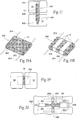
- Figs. 1A and 1B show representative alternative configurations of a device 10 sized and configured for the fixation of bone fractures (i.e., fixation of parts of the same bone) or for the fixation of bones which are to be fused (arthrodesed) (i.e. fixation of two or more individual bones that are adjacent and/or jointed).
- the device will sometimes be called a bone fixation/fusion device, to indicate that it can perform a fixation function between two or more individual bones), or a fusion function between two or more parts of the same bone, or both functions.
- bone segments or “adjacent bone regions” refer to either situation, i.e., a fracture line in a single bone or a space between different bone segments.
- the bone fixation/fusion device 10 comprises an elongated, stem-like structure.
- the device 10 can be formed - e.g., by machining, molding, or extrusion - from a material usable in the prosthetic arts, including, but not limited to, titanium, titanium alloys, tantalum, chrome cobalt, surgical steel, or any other total joint replacement metal.
- the bone fixation/fusion device 10 of the invention includes a triangular cross-section - as Fig. 1B shows for the purposes of illustration.
- the device can have further cross-sectional geometries in addition to the triangular cross-section, e.g., a generally curvilinear (i.e., round or oval) cross-section, or a square or rectangular cross-section.
- the bone fixation/fusion device 10 desirably includes a region 12 formed along at least a portion of its length to promote bony in-growth onto or into the surface of the device 10 and/or bony growth entirely through all or a portion of the device 10.
- the region 12 can comprise, e.g., through holes, and/or various surface patterns, and/or various surface textures, and/or pores, or combinations thereof.
- the device 10 can be coated or wrapped or surfaced treated to provide the bony in-growth or through-growth region 12 , or it can be formed from a material that itself inherently possesses a structure conducive to bony in-growth or through-growth, such as a porous mesh, hydroxyapetite, or other porous surface.
- the device 10 may further be covered with various other coatings such as antimicrobial, antithrombotic, and osteoinductive agents, or a combination thereof.
- the region 12 may be impregnated with such agents, if desired.
- Fig. 1 shows the region 12 as an open mesh configuration
- Fig. 2 shows the region 12 as beaded configuration
- Fig. 3 shows the region 12 as a trabecular configuration. Any configuration conducive to bony in-growth and/or bony through-growth will suffice.
- the bone fixation/fusion device 10 is inserted into a space between two adjacent bone surfaces, e.g., into a fracture site in a single bone or between two bones (e.g., adjacent vertebral bodies) which are to be fused together.
- the device 10 is shown being tapped into bone through bone segments 14 (i.e., across a fracture line or between adjacent bones to be fused) with a tap 16.
- the bone may be drilled first to facilitate insertion of the device 10.
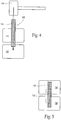
- the bony in-growth or through-growth region 12 along the surface of the device 10 accelerates bony in-growth or through-growth onto, into, or through the device 10. Bony in-growth or through-growth onto, into, or through the device 10 helps speed up the fusion process or fracture healing time.
- the bony in-growth or through-growth region 12 may extend along the entire outer surface of the device 10, as shown in Fig. 4 , or the bony in-growth or through-growth region 12 may cover just a specified distance on either side of the bone segments or fracture line, as shown in Fig. 5 .
- the size and configuration of the device 10 can be varied to accommodate the type and location of the bone to be treated as well as individual anatomy.
- the device 10 can be angled or tapered in a conical configuration.
- the degree of angle can be varied to accommodate specific needs or individual anatomy.
- a lesser degree of angle i.e., a more acute angle
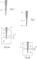
- the device 10 may also include a beveled distal tip 18 to further add in insertion of the device 10 into bone, as shown in Fig. 7 .
- the conical shape also helps drive the bone segments or fracture fragments together, reducing the gap (G) between the bone segments 14 or fracture segments.
- the device 10 is cannulated, having a central lumen or throughbore 20 extending through it, to assist in the placement of the device 10 within bone.
- Fig. 1B also shows a cannulated throughbore 20 in a different configuration.
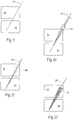
- the physician can insert a conventional guide pin 22 through the bone segments 14 by conventional methods, as Fig. 9 shows.
- a cannulated drill bit 24 can then be introduced over the guide pin 22, as seen in Fig. 10 .
- a single drill bit or multiple drill bits 24 can be employed to drill through bone fragments or bone surfaces to create a bore 26 of the desired size and configuration.
- the drill bit 24 is sized and configured to create a conical bore 26 similar in size and configuration to the device 10.
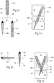
- the bore 26 is desirably sized and configured to permit tight engagement of the device 10 within the bore 26 and thereby restrict movement of the device 10 within the bore 26.
- the pre-formed bore 26 may be slightly smaller than the device 10, while still allowing the device 10 to be secured into position within the bore 26 by tapping.
- the drill bit 24 is then withdrawn.
- the device 10 is then inserted into the bore 26 over the guide pin 22, as Fig. 12 shows.
- the guide pin 22 is then withdrawn.
- the bone fixation/fusion device 10 itself can include screw-like threads along the body for screwing the device into place.
- the device 10 be self-tapping.
- the device 10 can be cannulated for use with a guide pin 22, or it need not be cannulated.
- Multiple devices 10 may be employed to provide additional stabilization. While the use of multiple devices 10 will now be described illustrating the use of multiple devices 10 of the same size and configuration, it is contemplated that the devices 10 may also be of different size and/or configuration, e.g., one device 10 is of a cylindrical configuration and a second device 10 is of a conical configuration.
- a series of devices 10 may be coupled together be any suitable means, e.g., by a snap fit engagement, or a groove and tab key arrangement, or by a Morse taper fit, or combinations thereof.
- a series of devices 10 are coupled by threaded engagement.
- a first device 10A includes a recess 28 at one end providing a series of internal threads 30.
- the first device 10 is of a cylindrical configuration, but may be of any desired configuration.
- the internal threads 30 couple with a series of complementary external threads 32 on a second device 10B of a similar or of a different configuration to couple the first and second devices 10A and 10B together.
- the devices 10A and 10B are desirably coupled together prior to being inserted into the pre-formed bore 26.
- the series of internal and external threads 30 and 32 provide an interlocking mechanism that permits a series of devices 10 to be stacked and connected to cover a larger area or multiple bone segments 14 (e.g., a bone having multiple fractures) and thereby provides additional stabilization, as seen in Fig. 14 .
- Fig. 15 illustrates another example in which a device 10' includes an opening or fenestration 34 to allow another device 10 to pass through, thereby providing additional stabilization.
- the fenestration 34 can be sized and configured to permit another device 10 to be passed through the device 10' at virtually any angle.
- the fenestration 34 can also be sized and configured to limit movement of the second device 10 relative to the second device 10'.
- the physician taps a first device 10' having a fenestration 34 through the bone segments.
- a second device 10 is then inserted (e.g., by tapping) through the fenestration 34 of the first device 10' into place.
- device 10' may also be adapted for coupling with another device 10A (e.g., by a series of external and internal threads), permitting the devices 10' and 10A to be additionally stacked and connected, as also shown in Fig. 16 .
- Fig. 17 illustrates an alternative form of a bone fixation/fusion device 100.
- device 100 includes a body 106 formed of a durable material that is not subject to significant bio-absorption or resorption by surrounding bone or tissue over time.
- the body 106 is intended to remain in place for a time sufficient to stabilize the fracture or fusion site.
- Such materials are well know in the prosthetic arts and include, e.g., titanium, titanium alloys, tantalum, chrome cobalt, surgical steel, or any other total joint replacement metal and/or ceramic, sintered glass, artificial bone, any uncemented metal or ceramic surface, or a combination thereof.
- the body 106 of the bone fixation/fusion device 100 may be formed from a suitable durable biologic material or a combination of metal and biologic material, such as a biocompatible bone-filling material.
- the body 106 of the device 100 may be molded from a flowable biologic material, e.g., acrylic bone cement, that is cured, e.g., by UV light, to a non-flowable or solid material.
- the body 106 of the device 100 may also include a bony in-growth or through-growth region 108, as already described in association with previous examples.
- the bone fixation/fusion device 100 includes at least one region associated with the body 106 that, in contrast to the body 106, comprises a material that is subject to more rapid in vivo bio-absorption or resorption by surrounding bone or tissue over time, e.g., within weeks or a few months.
- the resorbable material can comprise, e.g., polylactic acid (PLA), polyglycolic acid (PGA), poly(lactideglycolide) copolymers, polyanliydrides, cyclode, cirsns, polyorthoasters, n-vinyl alcohol, or other biosorbable polymers or like materials known or recognized in the prosthetic arts as having such characteristics.
- the bio-absorbable region is intended to facilitate implantation or placement of the body 106, but over time be absorbed to minimize the footprint of the implanted device 100 in the long run.
- the bioabsorbable region or regions can possess functionality to aid in the implantation process.
- Region 102 comprises a bioabsorbable screw region 102, which is desirably threaded or otherwise suitably configured to pierce bone and facilitate advancement of the device 100 into bone.
- region 104 comprises a bioabsorbable head region 104, which is desirably configured to mate with an installation instrument, e.g., a screwdriver, to further facilitate advancement and positioning of the bone fixation/fusion device 100 in bone.
- the bioabsorbable head 104 may also be sized and configured to temporarily anchor the device 100 within bone, e.g., the head 104 may be a slightly larger diameter than the body 106 of the device 100.
- the bioabsorbable screw portion 102 and head portion 104 are configured to provide an immediate benefit during the initial placement or position of the device 100, but over time be resorbed when they have served their initial purpose during implantation. This leaves the more durable and less resorbable body 106 behind, to serve its longer-term function of stabilizing the fracture or fusion site.
- a given bone fixation/fusion device can take various shapes and geometries.
- the bone fixation/fusion device 200 possesses a flattened rectangular (or wafer-like) configuration.
- a region 12 of the device 200 can be textured or treated, as previously described, to provide bony in-growth or through-growth.
- the bony in-growth or through-growth region 12 may extend along the entire device 200 (see Fig. 18A ) or along any portion or portions of the device 200 (see Fig. 18B ).
- the bone fixation/fusion device 200 is desirably sized and configured to be positioned to join two or more adjacent bone segments 14 (which can comprise a fracture site, a fusion site, or both), as Fig. 19 shows, to fix and to promote the fusion of the adjacent bone segments 14.
- the device 200 may also be sized and configured to fix and to promote fusion of multiple bone segments 14 or compound fractures, as Fig. 20 shows.
- Fig. 20 illustrates placement of the bone fixation/fusion device 200 sized and configured for the fixation and fusion of, for example, a first cuneiform (CE1), a second cuneiform (CE2), a first metatarsal (M1), and a second metatarsal (M2).
- one or more auxiliary fixation elements such as conventional orthopedic screws 206, may also be placed within and/or across the bone segments 14 by conventional techniques, to augment the stabilization of the bone segments 14 during the fusion process.
- the size and configuration of the bone fixation/fusion device 200 may be modified or adjusted in diverse ways to serve the intended stabilization function in diverse bone locations, bone geometries, or bone types, which are intended to be fused or repaired.
- the bone fixation/fusion device 200 can come in a family of different pre-established sizes and shapes, or it can be individually sized and configured to meet the requirements of a particular individual's anatomy.
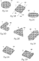
- a given bone fixation/fusion device 200 may take the form of a disc ( Fig. 21A ), a square ( Fig. 21B ), or an oval ( Fig. 21C ).
- the height, width, and length of a given bone fixation/fusion device 200 may be varied depending on the specific location and amount of bone to be crossed for stabilization.
- a given bone fixation/fusion device may possess a symmetric geometry, or an asymmetric or complex geometry - such as an L shape ( Fig. 21D ), a triangle ( Fig. 21E ), or rectangle with a triangular ends ( Fig. 22F ). Any combination of linear or curvilinear or rounded geometries is possible.
- a given bone fixation/fusion device can be cannulated to aid in guidance during placement or implantation.
- the device 200 can include a pair of opposing guide bores 202.
- the guide bores 202 are sized and configured to accommodate passage of guide pins 204, which are secured at the intended site of device placement.
- Other forms of cannulated devices 200 are shown in Figs. 21B and 24 . In this way, the bone fixation/fusion device 200 can be guided by the pins 204 to the intended bone placement site.
- the device may be profiled.
- the bone fixation/fusion device 200 may vary in height across its entire length of the device 200, to form a tapered wedge.
- the bone fixation/fusion device 200 may vary in height at one end only. In these arrangements, the bone fixation/fusion device 200 is desirably positioned with the area of greatest height in the proximal direction, which serves to wedge the device 200 into place within bone.
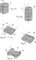
- the device can include one or more anti-rotational elements, which further stabilize and secure the device in the desired position within bone.
- the size and configuration of the anti-rotational elements may vary.
- the anti-rotational elements may comprise an array of fins 300 projecting from a stem-like device 10 ( Fig. 23A ), or an array of grooves 302 formed in a rectangular wafer device 200 ( Fig. 24 ), or wings 304 formed in a rectangular wafer device 200 ( Fig. 25 ), or flanges 306 projecting from a wafer device 200 ( Fig. 26 ).
- the anti-rotational elements can comprise (see Fig.
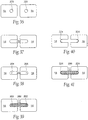
- two or more bone fixation/fusion devices 200 of the types generally described above may be assembled to form a composite bone fixation/fusion device having a desired size and configuration.
- the bodies of two bone fixation/fusion devices 200 each have a slot 208.
- Slot 208 in a first device 200 mates with a like or complementary slot 208 in a second device 200 to permit the assembly of a composite bone fixation/fusion device 310, which has a crossed, anti-rotational configuration for placement across bone segments 14.
- the crossed relation of the composite bone fixation/fusion device 310 has an increased surface area and adds further stability to the devices 200 in bone during the fusion process.
- the location, size, and configuration of the slots 208 may be varied to accommodate specific needs and a specific anatomical location as well as individual anatomy. It is also apparent that other mating configurations, e.g., groove and tab fitments, or snap-fit arrangements, or Morse taper fits, or threaded assemblies, can be use to assemble two or more bone fixation/fusion devices into a composite device 310.
- fixation or gripping plates 212 may be fitted to a given bone fixation/fusion device.
- the body of the bone fixation/fusion device 200 includes one or more attachment sites 210, e.g., slits or indentations, which are sized and configured to receive a selectively removable fixation or gripping plate 212.
- attachment sites 210 e.g., slits or indentations, which are sized and configured to receive a selectively removable fixation or gripping plate 212.
- the plate 212 When received within the slit 210, the plate 212 extends radially from the device to grip into bone and further secure the device 200 within bone.
- the attachment site 210 can include a tab 214, which mates with a notch 216 in the fixation plate 212 to secure the plate 212 within the device 200.
- tongue-and-groove fitments, or snap-fit arrangements, or threaded fitments, or Morse taper assemblies can be use to assemble one or more fixation or gripping plates to a bone fixation/fusion device.
- the fixation or gripping plate 212 is formed of durable biocompatible metal or bone substitute material, as previously described. In some cases, it may be desirable to provide a bony in-growth surface on at least a portion of the plate 212. Alternatively, the plate 212 may be formed of a bio-absorbable material, as already described.
- Figs. 30 and 31 illustrate examples in which the plates 212 present a generally blunt and flat configuration. It will be apparent to one of skill in the art that, however, that the plates 212 may also provide a sharpened or cutting edge or be otherwise sized and configured as necessary to accommodate specific location and individual anatomy. For example, the plate 212 may be rounded ( Fig. 32 ) or tapered ( Fig. 33 ).
- Fig. 34 illustrates an alternative example in which one or more fixation ridges 218 extend radially from the bone fixation/fusion device 200. Similar to the fixation plates 212, the ridges 218 may be variously sized and configured so as to grip into bone and further secure the bone fixation/fusion device 200 within bone.
- Fixation elements can be formed in situ.
- a bone fixation/fusion device 200 can include a malleable region 320 that normally presents a low-profile conducive to implantation.
- the profile of the malleable region 320 can be changed in situ after implantation to a radially enlarged or extended profile 326 that provides stabilization or an anti-rotational function to the device 200.
- the malleable region 320 is slotted (see Fig. 35A ) to accommodate placement of a wedge tool 324 carried for manipulation by a stylet or cannula 322 (see Fig. 35B ).
- the wedge tool 324 flays apart the slotted malleable region 320 (as Fig. 35B shows), to create the enlarged profile 326 for stabilization and/or rotation resistance.
- pilot holes 220 are drilled into adjacent bone segments 14 (e.g., along a fracture line in a single bone or between adjacent segments of different bones) by conventional surgical techniques.
- a single pilot hole 220 is drilled into each bone segment 14. It is to be understood that the number and configuration of the pilot holes 220 may vary as necessary or as desired.
- the physician can then then saw, using conventional methods, between the pilot holes 220 to prepare a cavity 222 to receive the device 200.
- Guide pins 204 may, if desired, be placed at opposing ends of the bored cavity 222, as seen in Fig. 38 . In this arrangement, as shown in Fig. 39 , the selected bone fixation/fusion device 200 is passed over the guide pins 204 to position the device 200 with the cavity 222. The guide pins 204 may then be removed. In an alternative arrangement, guide pins 204 need not be used, and the device 200 is manually inserted by the physician into the bore cavity 222.
- FIG. 40 and 41 An alternative example is illustrated in Figs. 40 and 41 .
- a c-shaped restraint 224 is placed against each end of the bored cavity 222.
- the selected bone fixation/fusion device 200 is then positioned between the restraints 222 such that the restraints 222 engage the device 200 to secure the device 200 within bone.
Description
- This application is a continuation-in-part of co-pending
U.S. Patent Application Serial No. 10/914,629, filed August 9, 2004 - This application relates generally to the fixation of bone.
- Many types of hardware are available both for fracture fixation and for the fixation of bones that are to fused (arthrodesed).
- Metal and absorbable screws are routinely used to fixate bone fractures and osteotomies. It is important to the successful outcome of the procedure that the screw is able to generate the compressive forces helpful in promoting bone healing.
-
WO 03/007839 -
US 2002/0049497 discloses a spinal implant for attaching two adjacent vertebrae. The implant comprises a body having first and second opposite surfaces, each surface including at least one protruding member for securing the body to the vertebrae. -
WO 01/17445 - According to the present invention there is provided a bone fixation/fusion device according to claim 1.
- The invention provides bone fixation/fusion devices for stabilizing bone segments, which can comprise parts of the same bone (e.g., fracture fixation) or two or more individual bones (e.g., fusion). The systems include a fixation/fusion device adapted for placement in
association with bone segments. - At least a portion of the device includes a porous region permitting bony in-growth and/or through-growth.
- In one embodiment, the device includes a first region of essentially non-resorbable material and a second region of essentially resorbable material.
- In one embodiment, the device includes a region that couples to another bone fixation/fusion device to form a composite device.
- In one embodiment, the device includes at least one stabilization element and/or anti-rotational element.
- The bone fixation/fusion device is elongated and includes a triangular cross-section. The device can have further cross-sectional geometries in addition to the triangular cross-section, e.g., a generally curvilinear (i.e., round or oval) cross-section, or a square or rectangular cross-section.
-
-
Figures 1 and 1B are perspective alternative views of a bone fixation/fusion device having a bony in-growth and/or through-growth region of a mesh configuration.Figure 1A depicts a comparative device andFigure 1B depicts a device of the invention. -
Figure 2 is a perspective view of a comparative embodiment of a bone fixation/fusion device having a bony in-growth and/or through-growth region of a beaded configuration. -
Figure 3 is a perspective view of a comparative embodiment of a bone fixation/fusion device
having a bony in-growth and/or through-growth region of a trabecular configuration. -
Figure 4 is a schematic view of a bone fixation/fusion device of the type shown inFig. 1 , being inserted in association with bone across a fracture line or between different bone segments. -
Figure 5 is a schematic view of a bone fixation/fusion device positioned in association with a fracture line or between different bone segments with a bony in-growth and/or through growth region extending across the fracture line or space between different bone segments. -
Figure 6 is a front plan view of an alternative example of a bone fixation/fusion device having a bony in-growth and/or bony through-growth region, in which the device has a conical configuration. -
Figure 7 is front plan view of an alternative example of a bone fixation/fusion device having a bony in-growth and/or through-growth region in which the device has a beveled distal tip. -
Figures 8A and 8B are schematics illustrating the insertion of a bone fixation/fusion device of the type shown inFig. 6 in association with a fracture line or between different bone segments. -
Figure 9 is a schematic illustrating a guidewire being introduced into bone in association with a fracture line or between different bone segments. -
Figure 10 is a schematic similar toFigure 9 and illustrating a drill bit being introduced over the guidewire. -
Figure 11 is a schematic similar toFigure 10 and illustrating a bore formed in the bone remaining after withdrawal of the drill bit. -
Figure 12 is a schematic similar toFigure 11 and illustrating insertion of a bone fixation/fusion device into the pre-formed bore. -
Figure 13 is an exploded front plan view illustrating the coupling of a pair of bone fixation/fusion by threaded engagement. -
Figure 14 is a schematic illustrating a pair of bone fixation/fusion devices coupled together and inserted in association with a fracture line or between different bone segments. -
Figure 15 is a front plan view illustrating passage of a bone fixation/fusion device through a fenestration in another bone fixation/fusion device. -
Figure 16 is a schematic illustrating the placement of a series of bone fixation/fusion devices in bone. -
Figure 17 is a top plan view of a bone fixation/fusion device positioned in association with a fracture line or between different bone segments. -
Figure 18A is a perspective view of an alternative example of a bone fixation/fusion device having a bony in-growth and/or bony through-growth region that extends substantially along the entire device. -
Figure 18B is a perspective view of a bone fixation/fusion device similar toFigure 18A and having a bony in-growth and/or bony through-growth region that extends along a portion of the device. -
Figure 19 is a top plan view of the bone fixation/fusion device ofFigure 18A in positioned in association with a fracture line or between different bone segments. -
Figure 20 is a top plan view of the bone fixation/fusion device ofFigure 18A positioned in association with a fracture line or between different bone segments and stabilized by fixation screws. -
Figures 21A to 21F are perspective views illustrating alternative configurations of bone fixation/fusion devices of a type shown inFig. 18A . -
Figures 22A and 22B are perspective views illustrating alternative examples of the bone fixation/fusion of a type shown inFig. 18A in which the device is profiled. -
Figures 23A and 23B are perspective views illustrating alternative examples of the bone fixation/fusion device of a type shown inFig. 1 with structural elements that provide an anti-rotational function. -
Figure 24 is a perspective view illustrating an alternative example of the bone fixation/fusion device of a type shownFig. 18A in which the device includes a series of grooves providing an anti-rotational function. -
Figure 25 is a perspective view illustrating an alternative example of the bone fixation/fusion device of a type shown inFig. 18A in which the device includes a pair of opposing wings providing an anti-rotational function. -
Figure 26 is a perspective view illustrating an alternative example of the bone fixation/fusion device ofFig. 18A in which the device includes a pair of opposing flanges providing an anti-rotational function. -
Figure 27 is an exploded view of a pair of coupled bone fixation/fusion devices that, when fitted together, form a composite bone fixation/fusion device. -
Figure 28 is an assembled view of the composite bone fixation/fusion device formed from the assembly of the bone fixation/fusion devices shown inFig. 27 . -
Figure 29 is a front view of the assembled composite bone fixation/fusion device ofFig. 28 positioned in association with a fracture line or between different bone segments. -
Figure 30 is a perspective view of an alternative example of the bone fixation/fusion device of a type shown inFig. 18A with fixation plates. -
Figure 31 is a perspective view of an alternative example of the bone fixation/fusion device ofFig. 30 . -
Figure 32 is a side view of an alternative example of a fixation plate having a rounded configuration. -
Figure 33 is a side view of an alternative example of a fixation plate having a tapered configuration. -
Figure 34 is a perspective view of an alternative example of the bone fixation/fusion device of a type shown inFigure 18A providing a series of radially-extending fixation ridges. -
Figures 35A and 35B are perspective views of a bone fixation/fusion device having a malleable region that can be flared or expanded to provide fixation and/or anti-rotation resistance. -
Figure 36 is a front plan view illustrating the drilling of pilot holes in adjacent bone segments, which can comprise a fracture line in the same bone or different bone segments. -
Figure 37 is a front plan view illustrating a cavity bored between the pilot holes to receive a bone fixation/fusion device. -
Figure 38 is a front plan view illustrating the placement of a pair of guide pins within the bored cavity. -
Figure 39 is a front plan view illustrating the placement of the bone fixation/fusion device into the cavity and removal of the guide pins. -
Figure 40 is a front plan view illustrating the placement of a pair of opposing c-shaped restraints within the bored cavity. -
Figure 41 is a front plan view illustrating the placement of the bone fixation/fusion device into the cavity within the restraints. - Although the disclosure hereof is detailed and exact to enable those skilled in the art to practice the invention, the physical embodiments herein disclosed merely exemplify the invention that may be embodied in other specific structure. While the preferred embodiment has been described, the details may be changed without departing from the invention, which is defined by the claims.
-
Figs. 1A and 1B show representative alternative configurations of adevice 10 sized and configured for the fixation of bone fractures (i.e., fixation of parts of the same bone) or for the fixation of bones which are to be fused (arthrodesed) (i.e. fixation of two or more individual bones that are adjacent and/or jointed). For the sake of shorthand, the device will sometimes be called a bone fixation/fusion device, to indicate that it can perform a fixation function between two or more individual bones), or a fusion function between two or more parts of the same bone, or both functions. As used herein, "bone segments" or "adjacent bone regions" refer to either situation, i.e., a fracture line in a single bone or a space between different bone segments. - In the example shown in
Fig. 1A and an embodiment of the invention as shown inFig. 1B , the bone fixation/fusion device 10 comprises an elongated, stem-like structure. Thedevice 10 can be formed - e.g., by machining, molding, or extrusion - from a material usable in the prosthetic arts, including, but not limited to, titanium, titanium alloys, tantalum, chrome cobalt, surgical steel, or any other total joint replacement metal. - The bone fixation/
fusion device 10 of the invention includes a triangular cross-section - asFig. 1B shows for the purposes of illustration. The device can have further cross-sectional geometries in addition to the triangular cross-section, e.g., a generally curvilinear (i.e., round or oval) cross-section, or a square or rectangular cross-section. - As
Figs. 2 and 3 show, the bone fixation/fusion device 10 desirably includes aregion 12 formed along at least a portion of its length to promote bony in-growth onto or into the surface of thedevice 10 and/or bony growth entirely through all or a portion of thedevice 10. - The
region 12 can comprise, e.g., through holes, and/or various surface patterns, and/or various surface textures, and/or pores, or combinations thereof. Thedevice 10 can be coated or wrapped or surfaced treated to provide the bony in-growth or through-growth region 12 , or it can be formed from a material that itself inherently possesses a structure conducive to bony in-growth or through-growth, such as a porous mesh, hydroxyapetite, or other porous surface. Thedevice 10 may further be covered with various other coatings such as antimicrobial, antithrombotic, and osteoinductive agents, or a combination thereof. Theregion 12 may be impregnated with such agents, if desired. - The configuration of the
region 12 can, of course, vary. By way of examples,Fig. 1 shows theregion 12 as an open mesh configuration;Fig. 2 shows theregion 12 as beaded configuration; andFig. 3 shows theregion 12 as a trabecular configuration. Any configuration conducive to bony in-growth and/or bony through-growth will suffice. - In use (see
Figs. 4 and 5 ), the bone fixation/fusion device 10 is inserted into a space between two adjacent bone surfaces, e.g., into a fracture site in a single bone or between two bones (e.g., adjacent vertebral bodies) which are to be fused together. InFig. 4 , thedevice 10 is shown being tapped into bone through bone segments 14 (i.e., across a fracture line or between adjacent bones to be fused) with atap 16. The bone may be drilled first to facilitate insertion of thedevice 10. The bony in-growth or through-growth region 12 along the surface of thedevice 10 accelerates bony in-growth or through-growth onto, into, or through thedevice 10. Bony in-growth or through-growth onto, into, or through thedevice 10 helps speed up the fusion process or fracture healing time. - The bony in-growth or through-
growth region 12 may extend along the entire outer surface of thedevice 10, as shown inFig. 4 , or the bony in-growth or through-growth region 12 may cover just a specified distance on either side of the bone segments or fracture line, as shown inFig. 5 . - The size and configuration of the
device 10 can be varied to accommodate the type and location of the bone to be treated as well as individual anatomy. - As
Fig. 6 shows, thedevice 10 can be angled or tapered in a conical configuration. The degree of angle can be varied to accommodate specific needs or individual anatomy. A lesser degree of angle (i.e., a more acute angle) decreases the risk of splitting the bone as thedevice 10 is tapped into the bone or thefracture segments 14. Thedevice 10 may also include a beveleddistal tip 18 to further add in insertion of thedevice 10 into bone, as shown inFig. 7 . As shown inFigs. 8A and 8B , the conical shape also helps drive the bone segments or fracture fragments together, reducing the gap (G) between thebone segments 14 or fracture segments. - In
Figs. 9 to 12 , thedevice 10 is cannulated, having a central lumen orthroughbore 20 extending through it, to assist in the placement of thedevice 10 within bone.Fig. 1B also shows a cannulatedthroughbore 20 in a different configuration. - In use, the physician can insert a
conventional guide pin 22 through thebone segments 14 by conventional methods, asFig. 9 shows. A cannulateddrill bit 24 can then be introduced over theguide pin 22, as seen inFig. 10 . A single drill bit ormultiple drill bits 24 can be employed to drill through bone fragments or bone surfaces to create abore 26 of the desired size and configuration. In the illustrated example, thedrill bit 24 is sized and configured to create aconical bore 26 similar in size and configuration to thedevice 10. Thebore 26 is desirably sized and configured to permit tight engagement of thedevice 10 within thebore 26 and thereby restrict movement of thedevice 10 within thebore 26. Thepre-formed bore 26 may be slightly smaller than thedevice 10, while still allowing thedevice 10 to be secured into position within thebore 26 by tapping. As seen inFig. 11 , thedrill bit 24 is then withdrawn. Thedevice 10 is then inserted into thebore 26 over theguide pin 22, asFig. 12 shows. Theguide pin 22 is then withdrawn. - Alternatively, the bone fixation/
fusion device 10 itself can include screw-like threads along the body for screwing the device into place. In the arrangement, thedevice 10 be self-tapping. Also in this arrangement, thedevice 10 can be cannulated for use with aguide pin 22, or it need not be cannulated. -
Multiple devices 10 may be employed to provide additional stabilization. While the use ofmultiple devices 10 will now be described illustrating the use ofmultiple devices 10 of the same size and configuration, it is contemplated that thedevices 10 may also be of different size and/or configuration, e.g., onedevice 10 is of a cylindrical configuration and asecond device 10 is of a conical configuration. - In many cases, it may be desirable to couple a series of
devices 10 together, e.g., to provide stabilization over a larger surface area. A series ofdevices 10 may be coupled together be any suitable means, e.g., by a snap fit engagement, or a groove and tab key arrangement, or by a Morse taper fit, or combinations thereof. In one example, a series ofdevices 10 are coupled by threaded engagement. As illustrated inFig. 13 , afirst device 10A includes arecess 28 at one end providing a series ofinternal threads 30. In the illustrated example, thefirst device 10 is of a cylindrical configuration, but may be of any desired configuration. Theinternal threads 30 couple with a series of complementaryexternal threads 32 on asecond device 10B of a similar or of a different configuration to couple the first andsecond devices - The
devices pre-formed bore 26. The series of internal andexternal threads devices 10 to be stacked and connected to cover a larger area or multiple bone segments 14 (e.g., a bone having multiple fractures) and thereby provides additional stabilization, as seen inFig. 14 . -
Fig. 15 illustrates another example in which a device 10' includes an opening orfenestration 34 to allow anotherdevice 10 to pass through, thereby providing additional stabilization. Thefenestration 34 can be sized and configured to permit anotherdevice 10 to be passed through the device 10' at virtually any angle. Thefenestration 34 can also be sized and configured to limit movement of thesecond device 10 relative to the second device 10'. - In use, and as shown in
Fig. 16 , the physician taps a first device 10' having afenestration 34 through the bone segments. Asecond device 10 is then inserted (e.g., by tapping) through thefenestration 34 of the first device 10' into place. - It is further contemplated that device 10' may also be adapted for coupling with another
device 10A (e.g., by a series of external and internal threads), permitting thedevices 10' and 10A to be additionally stacked and connected, as also shown inFig. 16 . -
Fig. 17 illustrates an alternative form of a bone fixation/fusion device 100. Similar to the type of bone fixation/fusion device 10 previously described,device 100 includes abody 106 formed of a durable material that is not subject to significant bio-absorption or resorption by surrounding bone or tissue over time. In other words, thebody 106 is intended to remain in place for a time sufficient to stabilize the fracture or fusion site. Such materials are well know in the prosthetic arts and include, e.g., titanium, titanium alloys, tantalum, chrome cobalt, surgical steel, or any other total joint replacement metal and/or ceramic, sintered glass, artificial bone, any uncemented metal or ceramic surface, or a combination thereof. Alternatively, thebody 106 of the bone fixation/fusion device 100 may be formed from a suitable durable biologic material or a combination of metal and biologic material, such as a biocompatible bone-filling material. Thebody 106 of thedevice 100 may be molded from a flowable biologic material, e.g., acrylic bone cement, that is cured, e.g., by UV light, to a non-flowable or solid material. - The
body 106 of thedevice 100 may also include a bony in-growth or through-growth region 108, as already described in association with previous examples. - Unlike the bone fixation/
fusion device 10, the bone fixation/fusion device 100 includes at least one region associated with thebody 106 that, in contrast to thebody 106, comprises a material that is subject to more rapid in vivo bio-absorption or resorption by surrounding bone or tissue over time, e.g., within weeks or a few months. The resorbable material can comprise, e.g., polylactic acid (PLA), polyglycolic acid (PGA), poly(lactideglycolide) copolymers, polyanliydrides, cyclode, cirsns, polyorthoasters, n-vinyl alcohol, or other biosorbable polymers or like materials known or recognized in the prosthetic arts as having such characteristics. The bio-absorbable region is intended to facilitate implantation or placement of thebody 106, but over time be absorbed to minimize the footprint of the implanteddevice 100 in the long run. - The bioabsorbable region or regions can possess functionality to aid in the implantation process. For example, as shown the illustrated example, there are two
bioabsorbable regions Region 102 comprises abioabsorbable screw region 102, which is desirably threaded or otherwise suitably configured to pierce bone and facilitate advancement of thedevice 100 into bone. Theother region 104 comprises abioabsorbable head region 104, which is desirably configured to mate with an installation instrument, e.g., a screwdriver, to further facilitate advancement and positioning of the bone fixation/fusion device 100 in bone. Thebioabsorbable head 104 may also be sized and configured to temporarily anchor thedevice 100 within bone, e.g., thehead 104 may be a slightly larger diameter than thebody 106 of thedevice 100. Thebioabsorbable screw portion 102 andhead portion 104 are configured to provide an immediate benefit during the initial placement or position of thedevice 100, but over time be resorbed when they have served their initial purpose during implantation. This leaves the more durable and lessresorbable body 106 behind, to serve its longer-term function of stabilizing the fracture or fusion site. - As previously disclosed, a given bone fixation/fusion device can take various shapes and geometries. For example, as shown in
Figs. 18A and 18B , the bone fixation/fusion device 200 possesses a flattened rectangular (or wafer-like) configuration. Aregion 12 of thedevice 200 can be textured or treated, as previously described, to provide bony in-growth or through-growth. The bony in-growth or through-growth region 12 may extend along the entire device 200 (seeFig. 18A ) or along any portion or portions of the device 200 (seeFig. 18B ). - The bone fixation/
fusion device 200 is desirably sized and configured to be positioned to join two or more adjacent bone segments 14 (which can comprise a fracture site, a fusion site, or both), asFig. 19 shows, to fix and to promote the fusion of theadjacent bone segments 14. Thedevice 200 may also be sized and configured to fix and to promote fusion ofmultiple bone segments 14 or compound fractures, asFig. 20 shows.Fig. 20 illustrates placement of the bone fixation/fusion device 200 sized and configured for the fixation and fusion of, for example, a first cuneiform (CE1), a second cuneiform (CE2), a first metatarsal (M1), and a second metatarsal (M2). - As shown in
Fig. 20 , one or more auxiliary fixation elements, such as conventionalorthopedic screws 206, may also be placed within and/or across thebone segments 14 by conventional techniques, to augment the stabilization of thebone segments 14 during the fusion process. - The size and configuration of the bone fixation/
fusion device 200 may be modified or adjusted in diverse ways to serve the intended stabilization function in diverse bone locations, bone geometries, or bone types, which are intended to be fused or repaired. The bone fixation/fusion device 200 can come in a family of different pre-established sizes and shapes, or it can be individually sized and configured to meet the requirements of a particular individual's anatomy. For the sake of illustration, by not limitation, a given bone fixation/fusion device 200 may take the form of a disc (Fig. 21A ), a square (Fig. 21B ), or an oval (Fig. 21C ). The height, width, and length of a given bone fixation/fusion device 200 may be varied depending on the specific location and amount of bone to be crossed for stabilization. A given bone fixation/fusion device may possess a symmetric geometry, or an asymmetric or complex geometry - such as an L shape (Fig. 21D ), a triangle (Fig. 21E ), or rectangle with a triangular ends (Fig. 22F ). Any combination of linear or curvilinear or rounded geometries is possible. - As before described, a given bone fixation/fusion device can be cannulated to aid in guidance during placement or implantation. For example, as shown in
Figs. 18A and 18B , thedevice 200 can include a pair of opposing guide bores 202. The guide bores 202 are sized and configured to accommodate passage of guide pins 204, which are secured at the intended site of device placement. Other forms of cannulateddevices 200 are shown inFigs. 21B and24 . In this way, the bone fixation/fusion device 200 can be guided by thepins 204 to the intended bone placement site. - To aid in stabilizing a given bone fixation/fusion device within bone, the device may be profiled. For example, as shown in
Fig. 22A , the bone fixation/fusion device 200 may vary in height across its entire length of thedevice 200, to form a tapered wedge. Alternatively, as shown inFig. 22B , the bone fixation/fusion device 200 may vary in height at one end only. In these arrangements, the bone fixation/fusion device 200 is desirably positioned with the area of greatest height in the proximal direction, which serves to wedge thedevice 200 into place within bone. - To also aid in stabilizing a given bone fixation/fusion device within bone, the device can include one or more anti-rotational elements, which further stabilize and secure the device in the desired position within bone. The size and configuration of the anti-rotational elements may vary. For example, the anti-rotational elements may comprise an array of
fins 300 projecting from a stem-like device 10 (Fig. 23A ), or an array ofgrooves 302 formed in a rectangular wafer device 200 (Fig. 24 ), orwings 304 formed in a rectangular wafer device 200 (Fig. 25 ), orflanges 306 projecting from a wafer device 200 (Fig. 26 ). The anti-rotational elements can comprise (seeFig. 23B ) an array ofbumps 308 orsurface projections 310 formed on all or a portion of the device, which can be either stem-like or wafer-like in its configuration. Any number of anti-rotational elements, or any configuration of anti-rotational elements, or any combinations of configurations can be provided to serve the functional objective of stabilization. - As also previously described, two or more bone fixation/
fusion devices 200 of the types generally described above may be assembled to form a composite bone fixation/fusion device having a desired size and configuration. For example, in the arrangement shown inFigs. 27 to 29 , the bodies of two bone fixation/fusion devices 200 each have aslot 208.Slot 208 in afirst device 200 mates with a like orcomplementary slot 208 in asecond device 200 to permit the assembly of a composite bone fixation/fusion device 310, which has a crossed, anti-rotational configuration for placement acrossbone segments 14. The crossed relation of the composite bone fixation/fusion device 310 has an increased surface area and adds further stability to thedevices 200 in bone during the fusion process. - It will be apparent to one of skill in the art that the location, size, and configuration of the
slots 208 may be varied to accommodate specific needs and a specific anatomical location as well as individual anatomy. It is also apparent that other mating configurations, e.g., groove and tab fitments, or snap-fit arrangements, or Morse taper fits, or threaded assemblies, can be use to assemble two or more bone fixation/fusion devices into acomposite device 310. - As shown in
Figs. 30 , fixation orgripping plates 212 may be fitted to a given bone fixation/fusion device. In the arrangement shown inFig. 30 , the body of the bone fixation/fusion device 200 includes one ormore attachment sites 210, e.g., slits or indentations, which are sized and configured to receive a selectively removable fixation orgripping plate 212. When received within theslit 210, theplate 212 extends radially from the device to grip into bone and further secure thedevice 200 within bone. - In an alternative example, shown in
Fig. 31 , theattachment site 210 can include atab 214, which mates with anotch 216 in thefixation plate 212 to secure theplate 212 within thedevice 200. - Other forms of interlocking or nesting configuration can be used. For example, tongue-and-groove fitments, or snap-fit arrangements, or threaded fitments, or Morse taper assemblies can be use to assemble one or more fixation or gripping plates to a bone fixation/fusion device.
- The fixation or
gripping plate 212 is formed of durable biocompatible metal or bone substitute material, as previously described. In some cases, it may be desirable to provide a bony in-growth surface on at least a portion of theplate 212. Alternatively, theplate 212 may be formed of a bio-absorbable material, as already described. -
Figs. 30 and 31 illustrate examples in which theplates 212 present a generally blunt and flat configuration. It will be apparent to one of skill in the art that, however, that theplates 212 may also provide a sharpened or cutting edge or be otherwise sized and configured as necessary to accommodate specific location and individual anatomy. For example, theplate 212 may be rounded (Fig. 32 ) or tapered (Fig. 33 ). -
Fig. 34 illustrates an alternative example in which one ormore fixation ridges 218 extend radially from the bone fixation/fusion device 200. Similar to thefixation plates 212, theridges 218 may be variously sized and configured so as to grip into bone and further secure the bone fixation/fusion device 200 within bone. - Fixation elements can be formed in situ. For example, as shown in
Fig. 35A , a bone fixation/fusion device 200 can include amalleable region 320 that normally presents a low-profile conducive to implantation. AsFig. 35B shows, the profile of themalleable region 320 can be changed in situ after implantation to a radially enlarged orextended profile 326 that provides stabilization or an anti-rotational function to thedevice 200. In the illustrated embodiment, themalleable region 320 is slotted (seeFig. 35A ) to accommodate placement of awedge tool 324 carried for manipulation by a stylet or cannula 322 (seeFig. 35B ). Thewedge tool 324 flays apart the slotted malleable region 320 (asFig. 35B shows), to create theenlarged profile 326 for stabilization and/or rotation resistance. - In use, and with reference to
Fig. 36 ,pilot holes 220 are drilled into adjacent bone segments 14 (e.g., along a fracture line in a single bone or between adjacent segments of different bones) by conventional surgical techniques. In the illustrated example, asingle pilot hole 220 is drilled into eachbone segment 14. It is to be understood that the number and configuration of thepilot holes 220 may vary as necessary or as desired. - As shown in
Fig. 37 , the physician can then then saw, using conventional methods, between thepilot holes 220 to prepare acavity 222 to receive thedevice 200. - Guide pins 204 may, if desired, be placed at opposing ends of the
bored cavity 222, as seen inFig. 38 . In this arrangement, as shown inFig. 39 , the selected bone fixation/fusion device 200 is passed over the guide pins 204 to position thedevice 200 with thecavity 222. The guide pins 204 may then be removed. In an alternative arrangement, guide pins 204 need not be used, and thedevice 200 is manually inserted by the physician into thebore cavity 222. - An alternative example is illustrated in
Figs. 40 and 41 . In this example, a c-shapedrestraint 224 is placed against each end of thebored cavity 222. The selected bone fixation/fusion device 200 is then positioned between therestraints 222 such that therestraints 222 engage thedevice 200 to secure thedevice 200 within bone. - The foregoing is considered as illustrative only of the principles of the invention. Furthermore, since numerous modifications and changes will readily occur to those skilled in the art, it is not desired to limit the invention to the exact construction and operation shown and described. While the preferred embodiment has been described, the details may be changed without departing from the invention, which is defined by the claims.
Claims (10)
- A bone fixation/fusion device (10) comprising a metal body adapted for placement transversely across a fracture line or transversely across a joint between two different bone segments, characterized in that at least a portion of the body includes a porous region (12) permitting bony in-growth and/or through-growth and in that the body includes a cannulated region and an elongated, rectilinear configuration of triangular cross-section.
- The device (10) of claim 1, wherein the body also includes a curvilinear configuration.
- The device (10) of claim 1, wherein the body includes a region that couples with another bone fixation/fusion device to form a composite device.
- The device (10) of claim 1, wherein the body includes a region that couples to a stabilization element.
- The device (10) of claim 1, wherein the body includes a first region of essentially non-resorbable material and a second region of essentially resorbable material.
- The device (10) of claim 5, wherein the second region comprises a bone penetrating shape.
- The device (10) of claim 6, wherein the bone penetrating shape comprises a screw.
- The device (10) of claim 5, wherein the second region is sized and configured to couple to an installation tool.
- The device (10) of claim 5, wherein the second region includes a function different than a function of the first region.
- The device of any one of the preceding claims, wherein the body is made of a metal selected from titanium, titanium alloys, tantalum, chrome cobalt and surgical steel.
Priority Applications (1)
| Application Number | Priority Date | Filing Date | Title |
|---|---|---|---|
| DE05782575T DE05782575T8 (en) | 2004-08-09 | 2005-08-03 | SYSTEMS AND METHOD FOR FIXING OR CONNECTING BONES |
Applications Claiming Priority (3)
| Application Number | Priority Date | Filing Date | Title |
|---|---|---|---|
| US10/914,629 US20060036251A1 (en) | 2004-08-09 | 2004-08-09 | Systems and methods for the fixation or fusion of bone |
| US11/136,141 US7922765B2 (en) | 2004-08-09 | 2005-05-24 | Systems and methods for the fixation or fusion of bone |
| PCT/US2005/027464 WO2006020463A1 (en) | 2004-08-09 | 2005-08-03 | Systems and methods for the fixation or fusion of bone |
Publications (3)
| Publication Number | Publication Date |
|---|---|
| EP1791480A1 EP1791480A1 (en) | 2007-06-06 |
| EP1791480A4 EP1791480A4 (en) | 2011-07-27 |
| EP1791480B1 true EP1791480B1 (en) | 2018-10-24 |
Family
ID=35800968
Family Applications (1)
| Application Number | Title | Priority Date | Filing Date |
|---|---|---|---|
| EP05782575.4A Active EP1791480B1 (en) | 2004-08-09 | 2005-08-03 | Bone fixation/fusion device |
Country Status (7)
| Country | Link |
|---|---|
| US (10) | US20060036251A1 (en) |
| EP (1) | EP1791480B1 (en) |
| JP (5) | JP5144261B2 (en) |
| AU (1) | AU2005274042A1 (en) |
| DE (1) | DE05782575T8 (en) |
| ES (1) | ES2706005T3 (en) |
| WO (1) | WO2006020463A1 (en) |
Families Citing this family (166)
| Publication number | Priority date | Publication date | Assignee | Title |
|---|---|---|---|---|
| US7537664B2 (en) | 2002-11-08 | 2009-05-26 | Howmedica Osteonics Corp. | Laser-produced porous surface |
| US7955357B2 (en) | 2004-07-02 | 2011-06-07 | Ellipse Technologies, Inc. | Expandable rod system to treat scoliosis and method of using the same |
| US8444693B2 (en) * | 2004-08-09 | 2013-05-21 | Si-Bone Inc. | Apparatus, systems, and methods for achieving lumbar facet fusion |
| US9662158B2 (en) | 2004-08-09 | 2017-05-30 | Si-Bone Inc. | Systems and methods for the fixation or fusion of bone at or near a sacroiliac joint |
| US8425570B2 (en) | 2004-08-09 | 2013-04-23 | Si-Bone Inc. | Apparatus, systems, and methods for achieving anterior lumbar interbody fusion |
| US8388667B2 (en) | 2004-08-09 | 2013-03-05 | Si-Bone, Inc. | Systems and methods for the fixation or fusion of bone using compressive implants |
| US20070156241A1 (en) * | 2004-08-09 | 2007-07-05 | Reiley Mark A | Systems and methods for the fixation or fusion of bone |
| US20180228621A1 (en) | 2004-08-09 | 2018-08-16 | Mark A. Reiley | Apparatus, systems, and methods for the fixation or fusion of bone |
| US9949843B2 (en) | 2004-08-09 | 2018-04-24 | Si-Bone Inc. | Apparatus, systems, and methods for the fixation or fusion of bone |
| US8470004B2 (en) | 2004-08-09 | 2013-06-25 | Si-Bone Inc. | Apparatus, systems, and methods for stabilizing a spondylolisthesis |
| US8414648B2 (en) * | 2004-08-09 | 2013-04-09 | Si-Bone Inc. | Apparatus, systems, and methods for achieving trans-iliac lumbar fusion |
| US20060036251A1 (en) | 2004-08-09 | 2006-02-16 | Reiley Mark A | Systems and methods for the fixation or fusion of bone |
| FR2884406B1 (en) | 2005-04-14 | 2008-10-17 | Memometal Technologies Soc Par | INTRAMEDULAR OSTEOSYNTHESIS DEVICE OF TWO BONE PARTS, IN PARTICULAR HAND AND / OR FOOT |
| CN101252888A (en) * | 2005-07-18 | 2008-08-27 | D·M·全 | Bi-polar bone screw assembly |
| US8202306B2 (en) * | 2005-09-12 | 2012-06-19 | Arthrex, Inc. | Mesh reinforced tissue anchor |
| US8728387B2 (en) | 2005-12-06 | 2014-05-20 | Howmedica Osteonics Corp. | Laser-produced porous surface |
| US8603171B2 (en) * | 2006-01-25 | 2013-12-10 | Mimedx Group, Inc. | Spinal disc implants with flexible keels and methods of fabricating implants |
| US7862502B2 (en) | 2006-10-20 | 2011-01-04 | Ellipse Technologies, Inc. | Method and apparatus for adjusting a gastrointestinal restriction device |
| US20080234762A1 (en) * | 2007-03-06 | 2008-09-25 | Zimmer Technology, Inc. | Self-tapping screw with resorbable tip |
| FR2913876B1 (en) | 2007-03-20 | 2009-06-05 | Memometal Technologies Soc Par | OSTEOSYNTHESIS DEVICE |
| US20090048675A1 (en) * | 2007-04-25 | 2009-02-19 | Bhatnagar Mohit K | Spinal Fusion Implants with Selectively Applied Bone Growth Promoting Agent |
| US8257395B2 (en) | 2007-09-21 | 2012-09-04 | Jmea Corporation | Spinal fixation with selectively applied bone growth promoting agent |
| US8241357B2 (en) | 2007-04-25 | 2012-08-14 | Jmea Corporation | Prosthesis with a selectively applied bone growth promoting agent |
| US20090018592A1 (en) * | 2007-07-13 | 2009-01-15 | Pitbladdo Richard B | Bone screw for orthopedic apparatus |
| US9101410B1 (en) | 2007-10-24 | 2015-08-11 | Robert E. Urrea | Facet joint fusion device and method for using same |
| US8057472B2 (en) | 2007-10-30 | 2011-11-15 | Ellipse Technologies, Inc. | Skeletal manipulation method |
| US11202707B2 (en) | 2008-03-25 | 2021-12-21 | Nuvasive Specialized Orthopedics, Inc. | Adjustable implant system |
| US8333804B1 (en) | 2008-03-27 | 2012-12-18 | Spinelogik, Inc. | Intervertebral fusion device and method of use |
| US8313528B1 (en) | 2008-03-27 | 2012-11-20 | Spinelogik, Inc. | Intervertebral fusion device and method of use |
| US20100211109A1 (en) * | 2008-08-14 | 2010-08-19 | Doerr Timothy E | Tack for spine fixation |
| US20110106170A1 (en) * | 2008-08-14 | 2011-05-05 | Doerr Timothy E | Tack for spine fixation |
| FR2935601B1 (en) | 2008-09-09 | 2010-10-01 | Memometal Technologies | INTRAMEDULLARY IMPLANT RESORBABLE BETWEEN TWO BONE OR TWO BONE FRAGMENTS |
| US11241257B2 (en) | 2008-10-13 | 2022-02-08 | Nuvasive Specialized Orthopedics, Inc. | Spinal distraction system |
| US8382756B2 (en) | 2008-11-10 | 2013-02-26 | Ellipse Technologies, Inc. | External adjustment device for distraction device |
| JP2012510852A (en) * | 2008-12-04 | 2012-05-17 | エスアイ−ボーン・インコーポレイテッド | System and method for bone fixation or adhesion at or near the sacroiliac joint |
| US9763697B2 (en) * | 2008-12-16 | 2017-09-19 | DePuy Synthes Products, Inc. | Anti-infective spinal rod with surface features |
| US8821555B2 (en) | 2009-02-11 | 2014-09-02 | Howmedica Osteonics Corp. | Intervertebral implant with integrated fixation |
| US8197490B2 (en) | 2009-02-23 | 2012-06-12 | Ellipse Technologies, Inc. | Non-invasive adjustable distraction system |
| US9622792B2 (en) | 2009-04-29 | 2017-04-18 | Nuvasive Specialized Orthopedics, Inc. | Interspinous process device and method |
| RU2016101629A (en) | 2009-09-04 | 2018-12-04 | Нувэйсив Спешилайзд Ортопэдикс, Инк. | DEVICE AND METHOD FOR BONE EXTENSION |
| WO2011057032A2 (en) | 2009-11-06 | 2011-05-12 | Mark Crawford | Spinal surgery apparatus and method |
| US9421109B2 (en) | 2010-01-13 | 2016-08-23 | Jcbd, Llc | Systems and methods of fusing a sacroiliac joint |
| WO2012174485A1 (en) | 2011-06-17 | 2012-12-20 | Jcbd, Llc | Sacroiliac joint implant system |
| US9381045B2 (en) | 2010-01-13 | 2016-07-05 | Jcbd, Llc | Sacroiliac joint implant and sacroiliac joint instrument for fusing a sacroiliac joint |
| BR112012017259A2 (en) | 2010-01-13 | 2016-08-23 | Jcbd Llc | sacroiliac joint fusion and fixation system |
| WO2014015309A1 (en) | 2012-07-20 | 2014-01-23 | Jcbd, Llc | Orthopedic anchoring system and methods |
| US10596004B2 (en) * | 2010-01-13 | 2020-03-24 | Jcbd, Llc | Spinopelvic fixation technology |
| US9333090B2 (en) | 2010-01-13 | 2016-05-10 | Jcbd, Llc | Systems for and methods of fusing a sacroiliac joint |
| US9427324B1 (en) | 2010-02-22 | 2016-08-30 | Spinelogik, Inc. | Intervertebral fusion device and method of use |
| US20110288652A1 (en) * | 2010-05-20 | 2011-11-24 | Indiana University Research & Technology Corporation | Materials and methods for treating critically sized defects in mouse bone |
| US9248043B2 (en) | 2010-06-30 | 2016-02-02 | Ellipse Technologies, Inc. | External adjustment device for distraction device |
| WO2012015976A1 (en) * | 2010-07-27 | 2012-02-02 | Ginn Richard S | System for sacro-iliac stabilization |
| US9220535B2 (en) * | 2010-10-26 | 2015-12-29 | Christian Röbling | Process for introducing a stabilizing element into a vertebral column |
| US20120109203A1 (en) * | 2010-11-01 | 2012-05-03 | Warsaw Orthopedic, Inc. | Spinous process implant with extended post |
| WO2012112396A2 (en) | 2011-02-14 | 2012-08-23 | Ellipse Technologies, Inc. | Device and method for treating fractured bones |
| JP2014519369A (en) | 2011-05-05 | 2014-08-14 | ザイガ テクノロジー インコーポレイテッド | Sacroiliac fusion system |
| US9113972B2 (en) | 2011-08-24 | 2015-08-25 | Pioneer Surgical Technology, Inc. | Apparatus and methods for immobilization and fusion of a synovial joint |
| US10743794B2 (en) | 2011-10-04 | 2020-08-18 | Nuvasive Specialized Orthopedics, Inc. | Devices and methods for non-invasive implant length sensing |
| US9820788B2 (en) | 2011-10-05 | 2017-11-21 | H. Lee Moffitt Cancer Center And Research Institute, Inc. | Bone fusion system |
| US10799367B2 (en) | 2011-10-05 | 2020-10-13 | H. Lee Moffitt Cancer Center And Research Institute, Inc. | Bone fusion system |
| WO2013066946A1 (en) | 2011-11-01 | 2013-05-10 | Ellipse Technologies, Inc. | Adjustable magnetic devices and methods of using same |
| US9615856B2 (en) * | 2011-11-01 | 2017-04-11 | Imds Llc | Sacroiliac fusion cage |
| US20130150965A1 (en) * | 2011-12-12 | 2013-06-13 | Alan G. Taylor | Fusion implant |
| US9554914B2 (en) * | 2011-12-12 | 2017-01-31 | Wright Medical Technology, Inc. | Fusion implant |
| EP2809252A4 (en) | 2012-01-31 | 2016-02-17 | Univ Toledo | Bioactive fusion device |
| WO2013134682A1 (en) | 2012-03-09 | 2013-09-12 | Si-Bone Inc. | Artificial si joint |
| JP2015509435A (en) * | 2012-03-09 | 2015-03-30 | エスアイ−ボーン・インコーポレイテッドSi−Bone, Inc. | Threaded implant |
| CN104334102A (en) | 2012-03-09 | 2015-02-04 | 西-博恩公司 | Integrated implant |
| US10363140B2 (en) | 2012-03-09 | 2019-07-30 | Si-Bone Inc. | Systems, device, and methods for joint fusion |
| CN104334092A (en) | 2012-05-04 | 2015-02-04 | 西-博恩公司 | Fenestrated implant |
| US10179014B1 (en) | 2012-06-01 | 2019-01-15 | Nuvasive, Inc. | Systems and methods for promoting sacroiliac joint fusion |
| US20130338714A1 (en) | 2012-06-15 | 2013-12-19 | Arvin Chang | Magnetic implants with improved anatomical compatibility |
| US20140012340A1 (en) * | 2012-07-05 | 2014-01-09 | Warsaw Orthopedic, Inc. | Sacro-iliac joint implant system and method |
| DE202012103384U1 (en) | 2012-09-05 | 2012-09-24 | Signus Medizintechnik Gmbh | Pelvic ring implant |
| US9044281B2 (en) | 2012-10-18 | 2015-06-02 | Ellipse Technologies, Inc. | Intramedullary implants for replacing lost bone |
| WO2015057604A1 (en) * | 2012-10-19 | 2015-04-23 | Tyber Medical Llc | Wedge osteotomy device and method of use |
| CN104902854B (en) | 2012-10-29 | 2017-10-03 | 诺威适骨科专科公司 | The adjustable apparatus scorching for treating knee endoprosthesis |
| WO2014078321A1 (en) * | 2012-11-13 | 2014-05-22 | Greenberg Louis E | Orthopedic implant having non-circular cross section and method of use thereof |
| US9737294B2 (en) | 2013-01-28 | 2017-08-22 | Cartiva, Inc. | Method and system for orthopedic repair |
| AU2014209124A1 (en) | 2013-01-28 | 2015-09-17 | Cartiva, Inc. | Systems and methods for orthopedic repair |
| US9179938B2 (en) | 2013-03-08 | 2015-11-10 | Ellipse Technologies, Inc. | Distraction devices and method of assembling the same |
| US10433880B2 (en) | 2013-03-15 | 2019-10-08 | Jcbd, Llc | Systems and methods for fusing a sacroiliac joint and anchoring an orthopedic appliance |
| US9717539B2 (en) | 2013-07-30 | 2017-08-01 | Jcbd, Llc | Implants, systems, and methods for fusing a sacroiliac joint |
| US9826986B2 (en) | 2013-07-30 | 2017-11-28 | Jcbd, Llc | Systems for and methods of preparing a sacroiliac joint for fusion |
| US10245087B2 (en) | 2013-03-15 | 2019-04-02 | Jcbd, Llc | Systems and methods for fusing a sacroiliac joint and anchoring an orthopedic appliance |
| WO2014146018A1 (en) | 2013-03-15 | 2014-09-18 | Jcbd, Llc | Systems and methods for fusing a sacroiliac joint and anchoring an orthopedic appliance |
| US9119732B2 (en) | 2013-03-15 | 2015-09-01 | Orthocision, Inc. | Method and implant system for sacroiliac joint fixation and fusion |
| US9585695B2 (en) | 2013-03-15 | 2017-03-07 | Woven Orthopedic Technologies, Llc | Surgical screw hole liner devices and related methods |
| US9510872B2 (en) | 2013-03-15 | 2016-12-06 | Jcbd, Llc | Spinal stabilization system |
| WO2014145902A1 (en) | 2013-03-15 | 2014-09-18 | Si-Bone Inc. | Implants for spinal fixation or fusion |
| US9743961B2 (en) * | 2013-06-24 | 2017-08-29 | The University Of Toledo | Bioactive fusion device |
| WO2015013479A2 (en) | 2013-07-24 | 2015-01-29 | Renovis Surgical Technologies, Inc. | Surgical implant devices incorporating porous surfaces |
| WO2015017593A1 (en) | 2013-07-30 | 2015-02-05 | Jcbd, Llc | Systems for and methods of fusing a sacroiliac joint |
| US10226242B2 (en) | 2013-07-31 | 2019-03-12 | Nuvasive Specialized Orthopedics, Inc. | Noninvasively adjustable suture anchors |
| US9801734B1 (en) | 2013-08-09 | 2017-10-31 | Nuvasive, Inc. | Lordotic expandable interbody implant |
| EP3052037B1 (en) | 2013-10-02 | 2022-08-24 | Kyocera Medical Technologies, Inc. | Surgical implant devices incorporating porous surfaces and a locking plate |
| US10751094B2 (en) | 2013-10-10 | 2020-08-25 | Nuvasive Specialized Orthopedics, Inc. | Adjustable spinal implant |
| US9839448B2 (en) * | 2013-10-15 | 2017-12-12 | Si-Bone Inc. | Implant placement |
| US11147688B2 (en) | 2013-10-15 | 2021-10-19 | Si-Bone Inc. | Implant placement |
| US10314631B2 (en) | 2013-12-17 | 2019-06-11 | H. Lee Moffitt Cancer Center And Research Institute, Inc. | Transdiscal screw |
| US9861375B2 (en) | 2014-01-09 | 2018-01-09 | Zyga Technology, Inc. | Undercutting system for use in conjunction with sacroiliac fusion |
| US9968464B2 (en) | 2014-01-17 | 2018-05-15 | Spine Wave, Inc. | Spinal fusion system |
| CN106456215B (en) | 2014-04-28 | 2020-04-10 | 诺威适骨科专科公司 | External adjustment device for adjusting a medical implant |
| US9801546B2 (en) | 2014-05-27 | 2017-10-31 | Jcbd, Llc | Systems for and methods of diagnosing and treating a sacroiliac joint disorder |
| US10045803B2 (en) | 2014-07-03 | 2018-08-14 | Mayo Foundation For Medical Education And Research | Sacroiliac joint fusion screw and method |
| WO2016019241A1 (en) | 2014-08-01 | 2016-02-04 | H. Lee Moffitt Cancer Center And Research Institute, Inc. | Expandable intervertebral cage |
| US8956394B1 (en) | 2014-08-05 | 2015-02-17 | Woven Orthopedic Technologies, Llc | Woven retention devices, systems and methods |
| US9907593B2 (en) | 2014-08-05 | 2018-03-06 | Woven Orthopedic Technologies, Llc | Woven retention devices, systems and methods |
| EP2995278A1 (en) * | 2014-09-09 | 2016-03-16 | Klinikum rechts der Isar der Technischen Universität München | Medical/surgical implant |
| US9943351B2 (en) | 2014-09-16 | 2018-04-17 | Woven Orthopedic Technologies, Llc | Woven retention devices, systems, packaging, and related methods |
| WO2016044731A1 (en) | 2014-09-18 | 2016-03-24 | Si-Bone Inc. | Implants for bone fixation or fusion |
| WO2016044739A1 (en) | 2014-09-18 | 2016-03-24 | Si-Bone Inc. | Matrix implant |
| US9452056B2 (en) | 2014-09-29 | 2016-09-27 | Biomet C.V. | Implants for fixation of the distal tibia |
| US10166022B2 (en) | 2014-09-29 | 2019-01-01 | Biomet C.V. | Method and apparatus for bone fixation |
| USD740427S1 (en) | 2014-10-17 | 2015-10-06 | Woven Orthopedic Technologies, Llc | Orthopedic woven retention device |
| US10383733B2 (en) | 2014-10-22 | 2019-08-20 | Biomet C.V. | Method and apparatus for bone fixation |
| JP6672289B2 (en) | 2014-10-23 | 2020-03-25 | ニューベイシブ スペシャライズド オーソペディックス,インコーポレイテッド | Teleadjustable interactive bone remodeling implant |
| US9931141B2 (en) | 2014-11-26 | 2018-04-03 | Ex Technology, Llc | Method and apparatus for joint fusion |
| BR112017013834A2 (en) | 2014-12-26 | 2019-11-19 | Nuvasive Specialized Orthopedics Inc | distraction systems and methods |
| AU2016200179B2 (en) | 2015-01-14 | 2020-09-17 | Stryker European Operations Holdings Llc | Spinal implant with porous and solid surfaces |
| US10603182B2 (en) | 2015-01-14 | 2020-03-31 | Stryker European Holdings I, Llc | Spinal implant with fluid delivery capabilities |
| WO2016134326A2 (en) | 2015-02-19 | 2016-08-25 | Nuvasive, Inc. | Systems and methods for vertebral adjustment |
| US9757168B2 (en) | 2015-03-03 | 2017-09-12 | Howmedica Osteonics Corp. | Orthopedic implant and methods of implanting and removing same |
| US10376206B2 (en) | 2015-04-01 | 2019-08-13 | Si-Bone Inc. | Neuromonitoring systems and methods for bone fixation or fusion procedures |
| CA2930123A1 (en) | 2015-05-18 | 2016-11-18 | Stryker European Holdings I, Llc | Partially resorbable implants and methods |
| WO2017024277A1 (en) | 2015-08-05 | 2017-02-09 | Woven Orthopedic Technologies, Llc | Tapping devices, systems and methods for use in bone tissue |
| US10586167B2 (en) * | 2015-09-24 | 2020-03-10 | Microsoft Technology Licensing, Llc | Regularized model adaptation for in-session recommendations |
| BR112018007347A2 (en) | 2015-10-16 | 2018-10-23 | Nuvasive Specialized Orthopedics, Inc. | adjustable devices for the treatment of knee arthritis |
| EP4275631A3 (en) | 2015-12-10 | 2024-02-28 | NuVasive Specialized Orthopedics, Inc. | External adjustment device for distraction device |
| US10039570B2 (en) * | 2015-12-10 | 2018-08-07 | Hamid Farzadfard | Orthopedic device for closed fracture reduction |
| ES2879405T3 (en) | 2016-01-28 | 2021-11-22 | Nuvasive Specialized Orthopedics Inc | Bone transport systems |
| WO2017139548A1 (en) | 2016-02-10 | 2017-08-17 | Nuvasive Specialized Orthopedics, Inc. | Systems and methods for controlling multiple surgical variables |
| US10751071B2 (en) | 2016-04-25 | 2020-08-25 | Imds Llc | Joint fusion instrumentation and methods |
| US10413332B2 (en) | 2016-04-25 | 2019-09-17 | Imds Llc | Joint fusion implant and methods |
| US10470807B2 (en) | 2016-06-03 | 2019-11-12 | Stryker European Holdings I, Llc | Intramedullary implant and method of use |
| CN110114041B (en) | 2016-06-23 | 2022-02-25 | 弗兰克·H·贝姆 | Minimally invasive surgical system for fusing sacroiliac joints |
| US9937055B1 (en) | 2016-11-28 | 2018-04-10 | Spine Wave, Inc. | Scoring implant trial and implant inserter for spinal fusion system |
| WO2018107114A1 (en) | 2016-12-09 | 2018-06-14 | Woven Orthopedic Technologies, LLC. | Retention devices, lattices and related systems and methods |
| CN106510906B (en) * | 2017-01-01 | 2019-01-25 | 常州华森医疗器械有限公司 | The support construction portion of POROUS TITANIUM Invasive lumbar fusion device |
| CN106667626B (en) * | 2017-01-01 | 2019-02-01 | 常州华森医疗器械有限公司 | POROUS TITANIUM Invasive lumbar fusion device and preparation method thereof |
| CN110678150B (en) | 2017-02-21 | 2021-11-05 | 拜欧米特制造有限责任公司 | Implant for bridging a bone defect |
| EP3592265B1 (en) | 2017-03-10 | 2023-09-20 | Paragon 28, Inc. | Bone implant devices |
| EP4245234A3 (en) | 2017-04-21 | 2023-11-29 | Stryker Corporation | Stabilization system and implant for preventing relative motion between sections of tissue |
| EP3678602A4 (en) | 2017-09-08 | 2021-10-06 | Pioneer Surgical Technology, Inc. | Intervertebral implants, instruments, and methods |
| US10603055B2 (en) | 2017-09-15 | 2020-03-31 | Jcbd, Llc | Systems for and methods of preparing and fusing a sacroiliac joint |
| US10835388B2 (en) | 2017-09-20 | 2020-11-17 | Stryker European Operations Holdings Llc | Spinal implants |
| WO2019067584A1 (en) | 2017-09-26 | 2019-04-04 | Si-Bone Inc. | Systems and methods for decorticating the sacroiliac joint |
| WO2019070801A1 (en) | 2017-10-05 | 2019-04-11 | Spinewave, Inc. | Modular inserter for anterior cervical cage |
| USD907771S1 (en) | 2017-10-09 | 2021-01-12 | Pioneer Surgical Technology, Inc. | Intervertebral implant |
| USD921898S1 (en) | 2017-12-22 | 2021-06-08 | Orthocision Inc. | Helical implant |
| WO2019152737A1 (en) | 2018-02-01 | 2019-08-08 | Genesys Spine | Material directing orthopedic anchor |
| WO2019191505A1 (en) | 2018-03-28 | 2019-10-03 | Si-Bone Inc. | Threaded implants and methods of use across bone segments |
| AU2019213392A1 (en) | 2018-08-09 | 2020-02-27 | Stryker European Operations Holdings, LLC | Interbody implants and optimization features thereof |
| EP3679898B1 (en) | 2019-01-11 | 2021-08-18 | Kilian Kraus | Implant for stabilizing and/or fusion of the sacroiliac joint |
| AU2020217806A1 (en) | 2019-02-07 | 2021-08-26 | Nuvasive Specialized Orthopedics, Inc. | Ultrasonic communication in medical devices |
| US11589901B2 (en) | 2019-02-08 | 2023-02-28 | Nuvasive Specialized Orthopedics, Inc. | External adjustment device |
| JP2022520101A (en) | 2019-02-14 | 2022-03-28 | エスアイ-ボーン・インコーポレイテッド | Implants for spinal fixation and / or fusion |
| US11369419B2 (en) | 2019-02-14 | 2022-06-28 | Si-Bone Inc. | Implants for spinal fixation and or fusion |
| WO2021108590A1 (en) | 2019-11-27 | 2021-06-03 | Si-Bone, Inc. | Bone stabilizing implants and methods of placement across si joints |
| BR112022018112A2 (en) | 2020-03-11 | 2022-11-08 | Exsomed Corp | ORTHOPEDIC IMPLANTS AND INSTRUMENTS TO SUPPLY THEM |
| WO2021231329A1 (en) | 2020-05-11 | 2021-11-18 | Gensano Llc | Cannulated bone implant |
| JP2023553120A (en) | 2020-12-09 | 2023-12-20 | エスアイ-ボーン・インコーポレイテッド | Sacroiliac joint stabilization implants and implant methods |
| US20220265327A1 (en) | 2021-02-23 | 2022-08-25 | Nuvasive Specialized Orthopedics, Inc. | Adjustable implant, system and methods |
| US11737787B1 (en) | 2021-05-27 | 2023-08-29 | Nuvasive, Inc. | Bone elongating devices and methods of use |
| WO2023064785A1 (en) | 2021-10-12 | 2023-04-20 | Lee Randall F | System and method for a medical implant with integrated propulsors |
| KR20230122791A (en) * | 2022-02-15 | 2023-08-22 | 신흥섭 | Bone fixation device for spinal fusion and surgical tool set including the same |
Citations (2)
| Publication number | Priority date | Publication date | Assignee | Title |
|---|---|---|---|---|
| WO2001017445A1 (en) * | 1999-09-03 | 2001-03-15 | Depuy International Limited | Bone splint |
| WO2003007839A2 (en) * | 2001-07-16 | 2003-01-30 | Depuy Products, Inc. | Devices form naturally occurring biologically derived |
Family Cites Families (322)
| Publication number | Priority date | Publication date | Assignee | Title |
|---|---|---|---|---|
| US2675801A (en) * | 1954-04-20 | Intramedbllary nail | ||
| US1951278A (en) * | 1932-02-13 | 1934-03-13 | Ericsson Ernst Axel Johan | Fracture nail |
| US2136471A (en) * | 1937-06-30 | 1938-11-15 | Rudolph H Schneider | Bone pin |
| US2243717A (en) * | 1938-09-20 | 1941-05-27 | Moreira Franciseo Elias Godoy | Surgical device |
| US2414882A (en) * | 1943-09-24 | 1947-01-28 | Herschel Leiter H | Fracture reduction apparatus |
| US2562419A (en) | 1948-04-05 | 1951-07-31 | George L Ferris | Expansion nut setting tool |
| US2697433A (en) | 1951-12-04 | 1954-12-21 | Max A Zehnder | Device for accurately positioning and guiding guide wires used in the nailing of thefemoral neck |
| US3076453A (en) | 1961-01-16 | 1963-02-05 | Raymond G Tronzo | Hip nail |
| US3506982A (en) * | 1965-06-21 | 1970-04-21 | Cleveland Clinic | Endoprosthetic joints |
| US3709218A (en) * | 1970-04-24 | 1973-01-09 | W Halloran | Combination intramedullary fixation and external bone compression apparatus |
| US3694821A (en) * | 1970-11-02 | 1972-10-03 | Walter D Moritz | Artificial skeletal joint |
| US3744488A (en) * | 1971-06-08 | 1973-07-10 | J Cox | Bone splint |
| US4059115A (en) | 1976-06-14 | 1977-11-22 | Georgy Stepanovich Jumashev | Surgical instrument for operation of anterior fenestrated spondylodessis in vertebral osteochondrosis |
| US4156943A (en) | 1977-08-24 | 1979-06-05 | Collier John P | High-strength porous prosthetic device and process for making the same |
| AT358715B (en) | 1978-09-04 | 1980-09-25 | Plansee Metallwerk | BUTCHING AND REJECTING DEVICE FOR BONE MARKING NAIL |
| US4341206A (en) * | 1978-12-19 | 1982-07-27 | Synthes Ag | Device for producing a hole in a bone |
| DE2901962A1 (en) | 1979-01-19 | 1980-07-24 | Max Bernhard Ulrich | DEVICE FOR ILIOSACRAL TRANSFIXATION OF A POOL FRACTURE |
| EP0023787B1 (en) * | 1979-07-25 | 1983-07-20 | University Of Exeter | Plugs for the medullary canal of a bone |
| US4399813A (en) * | 1981-01-22 | 1983-08-23 | Barber Forest C | Apparatus and method for removing a prosthesis embedded in skeletal bone |
| US4501269A (en) * | 1981-12-11 | 1985-02-26 | Washington State University Research Foundation, Inc. | Process for fusing bone joints |
| DE8214493U1 (en) * | 1982-05-18 | 1982-09-09 | Howmedica International, Inc. Zweigniederlassung Kiel, 2301 Schönkirchen | Bone nail for the treatment of fractures in the proximal thigh area |
| US4501289A (en) * | 1982-08-24 | 1985-02-26 | Pauliukonis Richard S | Fluid proportioning diverter valve |
| US4475545A (en) * | 1982-12-06 | 1984-10-09 | Ender Hans G | Bone-nail |
| JPS59200642A (en) | 1983-04-28 | 1984-11-14 | 三菱鉱業セメント株式会社 | Bone fixing nail |
| US4569338A (en) | 1984-02-09 | 1986-02-11 | Edwards Charles C | Sacral fixation device |
| US4612918A (en) | 1984-10-16 | 1986-09-23 | Barclay Slocum | Method of eliminating canine cauda equina syndrome |
| FR2575059B1 (en) * | 1984-12-21 | 1988-11-10 | Daher Youssef | SHORING DEVICE FOR USE IN A VERTEBRAL PROSTHESIS |
| US4622959A (en) * | 1985-03-05 | 1986-11-18 | Marcus Randall E | Multi-use femoral intramedullary nail |
| US4638799A (en) | 1985-06-13 | 1987-01-27 | Moore Robert R | Needle guide apparatus for discolysis procedures |
| US4773402A (en) | 1985-09-13 | 1988-09-27 | Isola Implants, Inc. | Dorsal transacral surgical implant |
| US4743256A (en) * | 1985-10-04 | 1988-05-10 | Brantigan John W | Surgical prosthetic implant facilitating vertebral interbody fusion and method |
| US4787378A (en) * | 1986-09-08 | 1988-11-29 | Sodhi Jitendra S | Self-retaining nail for fracture of neck of femur |
| JPS6368155A (en) | 1986-09-11 | 1988-03-28 | グンゼ株式会社 | Bone bonding pin |
| IT1214567B (en) * | 1986-12-02 | 1990-01-18 | Cremascoli G S P A | ENDOMIDOLLAR NAIL STRUCTURE, AND EQUIPMENT FOR ITS INSERTION INTO THE BONE. |
| US4834757A (en) * | 1987-01-22 | 1989-05-30 | Brantigan John W | Prosthetic implant |
| US4790303A (en) | 1987-03-11 | 1988-12-13 | Acromed Corporation | Apparatus and method for securing bone graft |
| GB8718627D0 (en) * | 1987-08-06 | 1987-09-09 | Showell A W Sugicraft Ltd | Spinal implants |
| US4846162A (en) * | 1987-09-14 | 1989-07-11 | Moehring H David | Orthopedic nail and method of bone fracture fixation |
| DE3734111A1 (en) | 1987-10-06 | 1989-04-20 | Mecron Med Prod Gmbh | INTERMEDIATE NAIL FOR TREATMENT OF BONE BREAKS ACCORDING TO THE PRINCIPLE OF MARBLE NAILING AND MARNEL TOOL |
| US7452359B1 (en) | 1988-06-13 | 2008-11-18 | Warsaw Orthopedic, Inc. | Apparatus for inserting spinal implants |
| US7534254B1 (en) * | 1988-06-13 | 2009-05-19 | Warsaw Orthopedic, Inc. | Threaded frusto-conical interbody spinal fusion implants |
| US7491205B1 (en) | 1988-06-13 | 2009-02-17 | Warsaw Orthopedic, Inc. | Instrumentation for the surgical correction of human thoracic and lumbar spinal disease from the lateral aspect of the spine |
| US6770074B2 (en) | 1988-06-13 | 2004-08-03 | Gary Karlin Michelson | Apparatus for use in inserting spinal implants |
| US7431722B1 (en) * | 1995-02-27 | 2008-10-07 | Warsaw Orthopedic, Inc. | Apparatus including a guard member having a passage with a non-circular cross section for providing protected access to the spine |
| AU7139994A (en) | 1988-06-13 | 1995-01-03 | Karlin Technology, Inc. | Apparatus and method of inserting spinal implants |
| US5609635A (en) * | 1988-06-28 | 1997-03-11 | Michelson; Gary K. | Lordotic interbody spinal fusion implants |
| US4961740B1 (en) * | 1988-10-17 | 1997-01-14 | Surgical Dynamics Inc | V-thread fusion cage and method of fusing a bone joint |
| SE462137B (en) * | 1988-10-18 | 1990-05-14 | Freddy Rafael Astudillo Ley | DEVICE FOR CONNECTING AN OPENING IN STERNUM |
| DE3844661C2 (en) | 1988-12-10 | 1994-05-11 | Imz Fertigung Vertrieb | Implantable fastener for extraoral applications |
| US5066296A (en) * | 1989-02-02 | 1991-11-19 | Pfizer Hopsital Products Group, Inc. | Apparatus for treating a fracture |
| US4950270A (en) | 1989-02-03 | 1990-08-21 | Boehringer Mannheim Corporation | Cannulated self-tapping bone screw |
| US5034013A (en) | 1989-04-24 | 1991-07-23 | Zimmer Inc. | Intramedullary nail |
| US5041118A (en) | 1989-04-28 | 1991-08-20 | Implant Technology Inc. | Femoral broach |
| US5139500A (en) | 1989-05-08 | 1992-08-18 | Schwartz Nathan H | Bone attachment system |
| US5458638A (en) | 1989-07-06 | 1995-10-17 | Spine-Tech, Inc. | Non-threaded spinal implant |
| US5290558A (en) * | 1989-09-21 | 1994-03-01 | Osteotech, Inc. | Flowable demineralized bone powder composition and its use in bone repair |
| US5059193A (en) | 1989-11-20 | 1991-10-22 | Spine-Tech, Inc. | Expandable spinal implant and surgical method |
| CH683065A5 (en) | 1990-03-20 | 1994-01-14 | Synthes Ag | Tibial intramedullary nail with adapted cross-section. |
| US5108397A (en) | 1990-04-19 | 1992-04-28 | Joseph White | Method and apparatus for stabilization of pelvic fractures |
| US5053035A (en) * | 1990-05-24 | 1991-10-01 | Mclaren Alexander C | Flexible intramedullary fixation rod |
| US5034011A (en) | 1990-08-09 | 1991-07-23 | Advanced Spine Fixation Systems Incorporated | Segmental instrumentation of the posterior spine |
| US5122141A (en) * | 1990-08-30 | 1992-06-16 | Zimmer, Inc. | Modular intramedullary nail |
| US5147402A (en) | 1990-12-05 | 1992-09-15 | Sulzer Brothers Limited | Implant for ingrowth of osseous tissue |
| US5190551A (en) * | 1990-12-14 | 1993-03-02 | Zimmer, Inc. | Controlled apparatus and method for extracting cement mantles from bone recesses |
| US5147367A (en) | 1991-02-22 | 1992-09-15 | Ellis Alfred B | Drill pin guide and method for orthopedic surgery |
| US5390683A (en) | 1991-02-22 | 1995-02-21 | Pisharodi; Madhavan | Spinal implantation methods utilizing a middle expandable implant |
| CA2062012C (en) | 1991-03-05 | 2003-04-29 | Randall D. Ross | Bioabsorbable interference bone fixation screw |
| GB9113578D0 (en) * | 1991-06-24 | 1991-08-14 | Howmedica | Intramedullary intertrochanteric fracture fixation appliance |
| EP0523926A3 (en) | 1991-07-15 | 1993-12-01 | Smith & Nephew Richards Inc | Prosthetic implants with bioabsorbable coating |
| US5242444A (en) | 1991-11-04 | 1993-09-07 | University Of Florida | Lumbosacral fixation and fusion method and device |
| US5443466A (en) * | 1991-12-13 | 1995-08-22 | Shah; Mrugesh K. | Method and apparatus for treating fractures of a bone |
| US5171279A (en) | 1992-03-17 | 1992-12-15 | Danek Medical | Method for subcutaneous suprafascial pedicular internal fixation |
| US5197961A (en) * | 1992-05-12 | 1993-03-30 | Castle Tris S | Toenail extender |
| US5433718A (en) * | 1992-08-20 | 1995-07-18 | Brinker; Mark | Antibiotic eluding intramedullary nail apparatus |
| SE510158C2 (en) | 1992-10-29 | 1999-04-26 | Medevelop Ab | Anchorage elements for supporting prostheses and the use of such anchorage elements for fixing dentures |
| FR2697742B1 (en) | 1992-11-06 | 1994-12-16 | Biomat | Osteosynthesis device for spinal consolidation. |
| US6984235B2 (en) | 1993-01-21 | 2006-01-10 | Acumed Llc | System for fusing joints |
| DE69434145T2 (en) * | 1993-06-10 | 2005-10-27 | Karlin Technology, Inc., Saugus | Wirbeldistraktor |
| US5334205A (en) | 1993-06-30 | 1994-08-02 | The United States Of America As Represented By The Secretary Of The Air Force | Sacroiliac joint fixation guide |
| US5480402A (en) * | 1993-08-05 | 1996-01-02 | Kim; Andrew C. | Shoulder compression interlocking system |
| JPH09503138A (en) * | 1993-10-04 | 1997-03-31 | エンドカレ・アクチェンゲゼルシャフト | Drill part, Kirschner wire with such a drill part, bone router, etc. |
| US7722678B2 (en) * | 1993-11-01 | 2010-05-25 | Biomet Manufacturing Corp. | Intramedullary compliant fixation |
| ES2144606T3 (en) * | 1994-05-23 | 2000-06-16 | Sulzer Spine Tech Inc | IMPLANT FOR INTERVERTEBRAL FUSION. |
| AU4089697A (en) | 1994-05-25 | 1998-03-19 | Roger P Jackson | Apparatus and method for spinal fixation and correction of spinal deformities |
| US5489284A (en) * | 1994-07-15 | 1996-02-06 | Smith & Nephew Richards Inc. | Cannulated modular intramedullary nail |
| FR2722980B1 (en) | 1994-07-26 | 1996-09-27 | Samani Jacques | INTERTEPINOUS VERTEBRAL IMPLANT |
| US5716358A (en) * | 1994-12-02 | 1998-02-10 | Johnson & Johnson Professional, Inc. | Directional bone fixation device |
| CN1134810A (en) * | 1995-02-17 | 1996-11-06 | 索发默达纳集团股份有限公司 | Improved interbody spinal fusion implants |
| US5591235A (en) | 1995-03-15 | 1997-01-07 | Kuslich; Stephen D. | Spinal fixation device |
| US5782919A (en) * | 1995-03-27 | 1998-07-21 | Sdgi Holdings, Inc. | Interbody fusion device and method for restoration of normal spinal anatomy |
| ES2236792T3 (en) | 1995-03-27 | 2005-07-16 | Sdgi Holdings, Inc. | IMPLANTS OF SPINAL FUSION AND INSTRUMENTS FOR INSERTION AND REVIEW. |
| US5626616A (en) | 1995-05-31 | 1997-05-06 | Speece; Conrad A. | Sacroiliac joint mobilization device |
| US5683391A (en) | 1995-06-07 | 1997-11-04 | Danek Medical, Inc. | Anterior spinal instrumentation and method for implantation and revision |
| US5667510A (en) | 1995-08-03 | 1997-09-16 | Combs; C. Robert | Joint fixation system and method |
| FR2737968B1 (en) | 1995-08-23 | 1997-12-05 | Biomat | IMPLANT FOR OSTEOSYNTHESIS OF SUPERIOR FEMALE EPIPHYSIS |
| US5643264A (en) | 1995-09-13 | 1997-07-01 | Danek Medical, Inc. | Iliac screw |
| US5766174A (en) | 1995-09-26 | 1998-06-16 | Orthologic Corporation | Intramedullary bone fixation device |
| US6423095B1 (en) | 1995-10-16 | 2002-07-23 | Sdgi Holdings, Inc. | Intervertebral spacers |
| US6143031A (en) | 1995-10-20 | 2000-11-07 | Synthes (U.S.A.) | Intervertebral implant with compressible shaped hollow element |
| IT1276590B1 (en) | 1995-11-03 | 1997-11-03 | Fernando Ricci | OSTEO INTEGRATED DENTAL IMPLANT WITH HYBRID ANCHORAGE |
| JPH09149906A (en) | 1995-11-29 | 1997-06-10 | Nagoya Rashi Seisakusho:Kk | Tool for curing bone disease |
| US5709683A (en) | 1995-12-19 | 1998-01-20 | Spine-Tech, Inc. | Interbody bone implant having conjoining stabilization features for bony fusion |
| US5672178A (en) | 1996-01-05 | 1997-09-30 | Petersen; Thomas D. | Fixation pin |
| US5766261A (en) | 1996-02-01 | 1998-06-16 | Osteonics Corp. | Femoral revision broach with modular trial components and method |
| US5868749A (en) * | 1996-04-05 | 1999-02-09 | Reed; Thomas M. | Fixation devices |
| DE29612269U1 (en) * | 1996-07-15 | 1996-09-12 | Aesculap Ag | Vertebral fusion implant |
| US6159214A (en) | 1996-07-31 | 2000-12-12 | Michelson; Gary K. | Milling instrumentation and method for preparing a space between adjacent vertebral bodies |
| JP3263806B2 (en) | 1996-09-18 | 2002-03-11 | タキロン株式会社 | Osteosynthesis pin |
| US5941885A (en) | 1996-10-08 | 1999-08-24 | Jackson; Roger P. | Tools for use in installing osteosynthesis apparatus utilizing set screw with break-off head |
| US6602293B1 (en) * | 1996-11-01 | 2003-08-05 | The Johns Hopkins University | Polymeric composite orthopedic implant |
| US6632224B2 (en) * | 1996-11-12 | 2003-10-14 | Triage Medical, Inc. | Bone fixation system |
| US5961554A (en) | 1996-12-31 | 1999-10-05 | Janson; Frank S | Intervertebral spacer |
| US7306628B2 (en) | 2002-10-29 | 2007-12-11 | St. Francis Medical Technologies | Interspinous process apparatus and method with a selectably expandable spacer |
| US6068630A (en) | 1997-01-02 | 2000-05-30 | St. Francis Medical Technologies, Inc. | Spine distraction implant |
| US5836948A (en) | 1997-01-02 | 1998-11-17 | Saint Francis Medical Technologies, Llc | Spine distraction implant and method |
| WO1998034552A1 (en) | 1997-02-06 | 1998-08-13 | Surgical Dynamics | Expandable non-threaded spinal fusion device |
| DE69838856T2 (en) | 1997-02-11 | 2008-12-11 | Warsaw Orthopedic, Inc., Warsaw | Plate for the anterior cervical spine with fixation system for one screw |
| US7066956B2 (en) | 1997-02-12 | 2006-06-27 | Arthrex, Inc. | Transverse fixation technique for ACL reconstruction using bone-tendon-bone graft |
| US5713904A (en) | 1997-02-12 | 1998-02-03 | Third Millennium Engineering, Llc | Selectively expandable sacral fixation screw-sleeve device |
| US5800440A (en) * | 1997-03-18 | 1998-09-01 | Johnson & Johnson Professional, Inc. | Device for inserting a surgical pin |
| US5897556A (en) | 1997-06-02 | 1999-04-27 | Sdgi Holdings, Inc. | Device for supporting weak bony structures |
| US7048762B1 (en) | 1997-08-27 | 2006-05-23 | Regeneration Technologies, Inc. | Elongated cortical bone implant |
| US5961522A (en) | 1997-11-10 | 1999-10-05 | Mehdizadeh; Hamid M. | Laminectomy chisel and guide apparatus |
| US6214049B1 (en) * | 1999-01-14 | 2001-04-10 | Comfort Biomedical, Inc. | Method and apparatus for augmentating osteointegration of prosthetic implant devices |
| US6036696A (en) * | 1997-12-19 | 2000-03-14 | Stryker Technologies Corporation | Guide-pin placement device and method of use |
| DE19801219A1 (en) | 1998-01-15 | 1999-07-22 | Holger K Dr Essiger | Bone nail |
| AU729213B2 (en) | 1998-03-05 | 2001-01-25 | Synthes Gmbh | Medullar pin with locking opening |
| US5928239A (en) | 1998-03-16 | 1999-07-27 | University Of Washington | Percutaneous surgical cavitation device and method |
| EP1067873A1 (en) | 1998-04-01 | 2001-01-17 | Bionx Implants Oy | Bioabsorbable surgical fastener for tissue treatment |
| US6241729B1 (en) | 1998-04-09 | 2001-06-05 | Sdgi Holdings, Inc. | Method and instrumentation for posterior interbody fusion |
| US6264657B1 (en) | 1998-04-21 | 2001-07-24 | Depuy Acromed, Inc. | Method for removing devices from bone |
| US6241769B1 (en) * | 1998-05-06 | 2001-06-05 | Cortek, Inc. | Implant for spinal fusion |
| US6800093B2 (en) * | 1998-05-06 | 2004-10-05 | Cortek, Inc. | Device for spinal fusion |
| JPH11318931A (en) | 1998-05-20 | 1999-11-24 | Ikufumi Yamada | Intramedullary nail facilitating distal lateral fixing and nail pulling |
| US6010507A (en) * | 1998-07-24 | 2000-01-04 | Rudloff; David A. C. | Repair of bone fracture using flexible fully or partially cannulated compression/decompression fixation element |
| EP1102568A1 (en) * | 1998-08-06 | 2001-05-30 | SDGI Holdings, Inc. | Composited intervertebral bone spacers |
| US6605294B2 (en) | 1998-08-14 | 2003-08-12 | Incept Llc | Methods of using in situ hydration of hydrogel articles for sealing or augmentation of tissue or vessels |
| US6406498B1 (en) | 1998-09-04 | 2002-06-18 | Bionx Implants Oy | Bioactive, bioabsorbable surgical composite material |
| CA2344891C (en) | 1998-10-30 | 2008-01-08 | Gary Karlin Michelson | Self-broaching, rotatable, push-in interbody fusion implant and method for deployment thereof |
| US6241732B1 (en) * | 1998-11-03 | 2001-06-05 | David W. Overaker | Biocompatible absorbable rivets and pins for use in surgical procedures |
| US6120504A (en) * | 1998-12-10 | 2000-09-19 | Biomet Inc. | Intramedullary nail having dual distal bore formation |
| US6517541B1 (en) * | 1998-12-23 | 2003-02-11 | Nenad Sesic | Axial intramedullary screw for the osteosynthesis of long bones |
| US6197062B1 (en) | 1999-01-11 | 2001-03-06 | Howmedica Osteonics, Corp. | Modular shoulder prosthesis system |
| ATE464847T1 (en) * | 1999-01-25 | 2010-05-15 | Warsaw Orthopedic Inc | INSTRUMENT FOR CREATION OF AN INTERVERBEL SPACE FOR ACCOMMODATION OF AN IMPLANT |
| US6086589A (en) | 1999-02-02 | 2000-07-11 | Spineology, Inc. | Method and device for fixing spondylolisthesis posteriorly |
| US6053916A (en) * | 1999-02-17 | 2000-04-25 | Moore; Michael R. | Sacroiliac implant |
| US6056749A (en) * | 1999-03-15 | 2000-05-02 | Spineology, Inc. | Method and device for fixing and correcting spondylolisthesis anteriorly |
| US6558423B1 (en) * | 1999-05-05 | 2003-05-06 | Gary K. Michelson | Interbody spinal fusion implants with multi-lock for locking opposed screws |
| US6607530B1 (en) * | 1999-05-10 | 2003-08-19 | Highgate Orthopedics, Inc. | Systems and methods for spinal fixation |
| US6221074B1 (en) * | 1999-06-10 | 2001-04-24 | Orthodyne, Inc. | Femoral intramedullary rod system |
| US6575991B1 (en) | 1999-06-17 | 2003-06-10 | Inrad, Inc. | Apparatus for the percutaneous marking of a lesion |
| US6497707B1 (en) * | 1999-07-23 | 2002-12-24 | Ethicon, Inc. | Graft fixation device combination |
| US6447516B1 (en) | 1999-08-09 | 2002-09-10 | Peter M. Bonutti | Method of securing tissue |
| US20040260286A1 (en) | 1999-10-08 | 2004-12-23 | Ferree Bret A. | Intradiscal devices with anti-extrusion keels |
| US6432107B1 (en) * | 2000-01-15 | 2002-08-13 | Bret A. Ferree | Enhanced surface area spinal fusion devices |
| JP4326134B2 (en) * | 1999-10-20 | 2009-09-02 | ウォーソー・オーソペディック・インコーポレーテッド | Method and apparatus for performing a surgical procedure |
| US7537616B1 (en) | 1999-10-20 | 2009-05-26 | Warsaw Orthopedic, Inc. | Impacted orthopedic bone support implant |
| EP1854433B1 (en) | 1999-10-22 | 2010-05-12 | FSI Acquisition Sub, LLC | Facet arthroplasty devices |
| US6673116B2 (en) | 1999-10-22 | 2004-01-06 | Mark A. Reiley | Intramedullary guidance systems and methods for installing ankle replacement prostheses |
| US6827740B1 (en) * | 1999-12-08 | 2004-12-07 | Gary K. Michelson | Spinal implant surface configuration |
| WO2001041681A1 (en) | 1999-12-10 | 2001-06-14 | Nuvasive, Inc. | Facet screw and bone allograft intervertebral support and fusion system |
| US6558386B1 (en) | 2000-02-16 | 2003-05-06 | Trans1 Inc. | Axial spinal implant and method and apparatus for implanting an axial spinal implant within the vertebrae of the spine |
| US6409768B1 (en) * | 2000-03-16 | 2002-06-25 | Slobodan Tepic | Screw anchored joint prosthesis |
| US6565566B1 (en) | 2000-03-22 | 2003-05-20 | Spinal Concepts, Inc. | Sacral screw assembly and method |
| DE60117377T2 (en) | 2000-05-25 | 2006-10-12 | Orthoplex Llc, Boston | ANCHORING SYSTEM FOR FIXING OBJECTS TO BONE |
| EP1292239B1 (en) * | 2000-06-23 | 2013-02-13 | University Of Southern California | Percutaneous vertebral fusion system |
| US6579293B1 (en) * | 2000-08-02 | 2003-06-17 | Rama E. Chandran | Intramedullary rod with interlocking oblique screw for tibio-calcaneal arthrodesis |
| US20020038123A1 (en) * | 2000-09-20 | 2002-03-28 | Visotsky Jeffrey L. | Osteotomy implant |
| US6527775B1 (en) | 2000-09-22 | 2003-03-04 | Piper Medical, Inc. | Intramedullary interlocking fixation device for the distal radius |
| US20040073216A1 (en) | 2000-10-05 | 2004-04-15 | The Cleveland Clinic Foundation | Apparatus and method for attaching adjacent bones |
| ATE296073T1 (en) * | 2000-10-11 | 2005-06-15 | Michael D Mason | TRANSPLANTLESS SPINE FUSION DEVICE |
| US6740088B1 (en) | 2000-10-25 | 2004-05-25 | Sdgi Holdings, Inc. | Anterior lumbar plate and method |
| US6605090B1 (en) * | 2000-10-25 | 2003-08-12 | Sdgi Holdings, Inc. | Non-metallic implant devices and intra-operative methods for assembly and fixation |
| DE10055891A1 (en) | 2000-11-10 | 2002-06-06 | Biedermann Motech Gmbh | bone screw |
| FR2817463B1 (en) * | 2000-12-05 | 2003-04-04 | Stryker Spine Sa | IN-SITU DISTRACTABLE SPINAL INTERSOMATIC IMPLANT |
| US6692501B2 (en) * | 2000-12-14 | 2004-02-17 | Gary K. Michelson | Spinal interspace shaper |
| US20020169507A1 (en) | 2000-12-14 | 2002-11-14 | David Malone | Interbody spine fusion cage |
| US6743257B2 (en) * | 2000-12-19 | 2004-06-01 | Cortek, Inc. | Dynamic implanted intervertebral spacer |
| FR2818530B1 (en) | 2000-12-22 | 2003-10-31 | Spine Next Sa | INTERVERTEBRAL IMPLANT WITH DEFORMABLE SHIM |
| US6635059B2 (en) | 2001-01-03 | 2003-10-21 | Bernard L. Randall | Cannulated locking screw system especially for transiliac implant |
| US6306140B1 (en) * | 2001-01-17 | 2001-10-23 | Synthes (Usa) | Bone screw |
| DE60224850T2 (en) * | 2001-02-04 | 2009-01-22 | Warsaw Orthopedic, Inc., Warsaw | Instrumentation for introducing and positioning an expandable intervertebral fusion implant |
| DE60214170T2 (en) | 2001-02-13 | 2007-07-19 | T. Teresa San Jose Yeung | Compression device and trocar for repairing an intervertebral prosthesis |
| US7235081B2 (en) | 2001-07-16 | 2007-06-26 | Spinecore, Inc. | Wedge plate inserter/impactor and related methods for use in implanting an artificial intervertebral disc |
| US6989032B2 (en) | 2001-07-16 | 2006-01-24 | Spinecore, Inc. | Artificial intervertebral disc |
| US20030078660A1 (en) | 2001-02-15 | 2003-04-24 | Dale Clifford | Orthopedic implant and method for orthopedic treatment |
| US6673075B2 (en) * | 2001-02-23 | 2004-01-06 | Albert N. Santilli | Porous intervertebral spacer |
| US6663656B2 (en) * | 2001-02-26 | 2003-12-16 | Arthrex, Inc. | Torque driver for interference screw |
| US6896680B2 (en) * | 2001-03-01 | 2005-05-24 | Gary K. Michelson | Arcuate dynamic lordotic guard with movable extensions for creating an implantation space posteriorly in the lumbar spine |
| ATE556661T1 (en) * | 2001-03-01 | 2012-05-15 | Warsaw Orthopedic Inc | DYNAMIC LORDOSIC PROTECTION WITH MOVABLE EXTENSIONS FOR CREATING A POSTERIOR IMPLANTATION SPACE IN THE LUMBAR SPINE AND METHOD OF USE THEREOF |
| DE50208067D1 (en) | 2001-03-02 | 2006-10-19 | Woodwelding Ag | Implants and device for connecting tissue parts |
| US6666868B2 (en) * | 2001-03-02 | 2003-12-23 | Medicinelodge, Inc. | Two-part orthopedic fastener |
| US6595998B2 (en) * | 2001-03-08 | 2003-07-22 | Spinewave, Inc. | Tissue distraction device |
| US7066943B2 (en) | 2001-03-30 | 2006-06-27 | Zirkle Jr Lewis G | Method and apparatus for locating and stabilizing an orthopedic implant |
| US6511481B2 (en) * | 2001-03-30 | 2003-01-28 | Triage Medical, Inc. | Method and apparatus for fixation of proximal femoral fractures |
| JP4499310B2 (en) | 2001-04-12 | 2010-07-07 | 経憲 武井 | Surgical instruments |
| US6471707B1 (en) * | 2001-05-11 | 2002-10-29 | Biomet | Bone screw having bioresorbable proximal shaft portion |
| US20020183858A1 (en) * | 2001-06-05 | 2002-12-05 | Contiliano Joseph H. | Attachment of absorbable tissue scaffolds to scaffold fixation devices |
| US20040176287A1 (en) | 2001-06-08 | 2004-09-09 | Harrison Andrew James | Bmp binding proteins for use in bone or cartilage regeneration |
| DE10129490A1 (en) | 2001-06-21 | 2003-01-02 | Helmut Mueckter | Implantable screw for stabilization of joint or bone fracture, has flexible shaft which interconnects proximal head portion and distal insertion portion of elongated screw body |
| US6652528B2 (en) * | 2001-07-17 | 2003-11-25 | Biomet, Inc. | Intramedullary nail with modular sleeve |
| US6524314B1 (en) * | 2001-08-24 | 2003-02-25 | John C. Dean | Interlocking intramedullary nail |
| CA2356535A1 (en) | 2001-09-04 | 2003-03-04 | Sylvio Quesnel | Intervertebral fusion device |
| US6916321B2 (en) * | 2001-09-28 | 2005-07-12 | Ethicon, Inc. | Self-tapping resorbable two-piece bone screw |
| US6835197B2 (en) * | 2001-10-17 | 2004-12-28 | Christoph Andreas Roth | Bone fixation system |
| US6709439B2 (en) | 2001-10-30 | 2004-03-23 | Depuy Spine, Inc. | Slaphammer tool |
| US7008431B2 (en) * | 2001-10-30 | 2006-03-07 | Depuy Spine, Inc. | Configured and sized cannula |
| US6723099B1 (en) | 2001-11-08 | 2004-04-20 | Biomet, Inc. | Three sided tack for bone fixation |
| FR2832054B1 (en) | 2001-11-15 | 2004-09-10 | Rene Louis | POSTERIOR VERTEBRAL JOINT PROSTHESIS |
| US6572620B1 (en) * | 2001-11-16 | 2003-06-03 | Lew C. Schon | Modular, blade-rod, intramedullary fixation device |
| US6991461B2 (en) | 2001-12-28 | 2006-01-31 | Gittleman Neal B | Expandable dental implant apparatus |
| US6740118B2 (en) * | 2002-01-09 | 2004-05-25 | Sdgi Holdings, Inc. | Intervertebral prosthetic joint |
| US7527649B1 (en) | 2002-02-15 | 2009-05-05 | Nuvasive, Inc. | Intervertebral implant and related methods |
| US20030181982A1 (en) | 2002-03-04 | 2003-09-25 | Spineology, Inc. | No-profile, lumbo-sacral fixation device and method |
| US7819869B2 (en) * | 2004-11-15 | 2010-10-26 | Kimberly-Clark Inc. | Methods of treating the sacroilac region of a patient's body |
| ES2287460T3 (en) * | 2002-03-11 | 2007-12-16 | Spinal Concepts Inc. | INSTRUMENTATION TO IMPLEMENT COLUMN IMPLANTS. |
| US6991653B2 (en) * | 2002-03-21 | 2006-01-31 | Sdgi Holdings, Inc. | Vertebral body and disc space replacement devices |
| US20040010315A1 (en) | 2002-03-29 | 2004-01-15 | Song John K. | Self-expanding intervertebral device |
| US8696749B2 (en) | 2002-04-25 | 2014-04-15 | Blackstone Medical, Inc. | Artificial intervertebral disc |
| US6770095B2 (en) | 2002-06-18 | 2004-08-03 | Depuy Acroned, Inc. | Intervertebral disc |
| ATE389359T1 (en) * | 2002-06-26 | 2008-04-15 | Synthes Gmbh | BONE FIXATION ELEMENT |
| US20050143837A1 (en) | 2002-06-27 | 2005-06-30 | Ferree Bret A. | Arthroplasty devices configured to reduce shear stress |
| US7175663B1 (en) * | 2003-10-08 | 2007-02-13 | Biomet Manufacturing Corp. | Shoulder implant assembly |
| AU2003261286B2 (en) | 2002-07-19 | 2009-10-29 | Interventional Spine, Inc. | Method and apparatus for spinal fixation |
| WO2004008976A1 (en) | 2002-07-19 | 2004-01-29 | Osteotech, Inc. | Chisels and procedure for insertion of spinal implant in a spinal disc space |
| US7001386B2 (en) * | 2002-07-23 | 2006-02-21 | Advanced Orthopaedic Solutions, Inc. | Intramedullary nail for long bone fractures |
| US20040087948A1 (en) | 2002-08-29 | 2004-05-06 | Loubert Suddaby | Spinal facet fixation device |
| ES2343951T3 (en) | 2002-09-24 | 2010-08-13 | Bogomir Gorensek | STABILIZING DEVICE FOR INTERVERTEBRAL DISK AND METHODS FOR IT. |
| DE10246386B4 (en) | 2002-10-04 | 2008-08-07 | Biedermann Motech Gmbh | Bone screw, bone fixation device and retaining element |
| US6966929B2 (en) | 2002-10-29 | 2005-11-22 | St. Francis Medical Technologies, Inc. | Artificial vertebral disk replacement implant with a spacer |
| US20060030852A1 (en) | 2002-11-13 | 2006-02-09 | Sevrain Lionel C | Anchoring system for fixing objects to bones |
| US7641677B2 (en) | 2002-11-20 | 2010-01-05 | Orthopediatrics Corp. | Compression bone fragment wire |
| US7175625B2 (en) * | 2002-11-25 | 2007-02-13 | Triage Medical | Soft tissue anchor and method of using same |
| US20050124993A1 (en) | 2002-12-02 | 2005-06-09 | Chappuis James L. | Facet fusion system |
| US7223269B2 (en) | 2002-12-02 | 2007-05-29 | Chappuis James L | Facet fusion system |
| US7776042B2 (en) | 2002-12-03 | 2010-08-17 | Trans1 Inc. | Methods and apparatus for provision of therapy to adjacent motion segments |
| US7204852B2 (en) * | 2002-12-13 | 2007-04-17 | Spine Solutions, Inc. | Intervertebral implant, insertion tool and method of inserting same |
| AU2003297195A1 (en) * | 2002-12-17 | 2004-07-22 | Amedica Corporation | Total disc implant |
| DE10260222B4 (en) * | 2002-12-20 | 2008-01-03 | Biedermann Motech Gmbh | Tubular element for an implant and implant to be used in spine or bone surgery with such an element |
| US7500991B2 (en) * | 2002-12-31 | 2009-03-10 | Depuy Acromed, Inc. | Banana cage |
| US7048764B2 (en) | 2003-01-07 | 2006-05-23 | Ferree Bret A | Artificial disc replacements with articulating components |
| USD493533S1 (en) | 2003-02-14 | 2004-07-27 | Nuvasive, Inc. | Intervertebral implant |
| US6669529B1 (en) | 2003-02-25 | 2003-12-30 | Joseph L. Scaries | Turkey call |
| US20040176853A1 (en) | 2003-03-05 | 2004-09-09 | Sennett Andrew R. | Apparatus and method for spinal fusion using posteriorly implanted devices |
| WO2004080356A2 (en) * | 2003-03-07 | 2004-09-23 | Smart Disc, Inc. | Spinal implant with securement spikes |
| US7648509B2 (en) | 2003-03-10 | 2010-01-19 | Ilion Medical Llc | Sacroiliac joint immobilization |
| AU2003213968A1 (en) * | 2003-04-10 | 2004-11-01 | Synthes Ag Chur | Device for the temporary splinting of toes |
| US7601155B2 (en) | 2003-05-20 | 2009-10-13 | Petersen Thomas D | Instruments and method for minimally invasive surgery for total hips |
| JP4054291B2 (en) * | 2003-07-11 | 2008-02-27 | スミス・アンド・ネフュー株式会社 | Ligament reconstruction tool and ligament reconstruction method |
| US7575572B2 (en) | 2003-07-15 | 2009-08-18 | Spinal Generations, Llc | Method and device for delivering medicine to bone |
| EP1648348B1 (en) | 2003-07-24 | 2015-06-17 | Tecomet Inc. | Assembled non-random foams |
| FR2858546B1 (en) * | 2003-08-04 | 2006-04-28 | Spine Next Sa | INTERVERTEBRAL DISC PROSTHESIS |
| US8062365B2 (en) | 2003-08-04 | 2011-11-22 | Warsaw Orthopedic, Inc. | Bone supporting devices with bio-absorbable end members |
| US9254137B2 (en) | 2003-08-29 | 2016-02-09 | Lanterna Medical Technologies Ltd | Facet implant |
| GB0320287D0 (en) * | 2003-08-29 | 2003-10-01 | Stanmore Implants Worldwide | Shoulder joint prosthetic system |
| US8388690B2 (en) | 2003-10-03 | 2013-03-05 | Linvatec Corporation | Osteotomy system |
| US20050080415A1 (en) | 2003-10-14 | 2005-04-14 | Keyer Thomas R. | Polyaxial bone anchor and method of spinal fixation |
| US7896917B2 (en) | 2003-10-15 | 2011-03-01 | Biomet Sports Medicine, Llc | Method and apparatus for graft fixation |
| US7530993B2 (en) * | 2003-10-23 | 2009-05-12 | Trans1 Inc. | Method of spinal fixation |
| US7699852B2 (en) * | 2003-11-19 | 2010-04-20 | Zimmer Spine, Inc. | Fenestrated bone tap and method |
| US20050149192A1 (en) | 2003-11-20 | 2005-07-07 | St. Francis Medical Technologies, Inc. | Intervertebral body fusion cage with keels and implantation method |
| US7723395B2 (en) * | 2004-04-29 | 2010-05-25 | Kensey Nash Corporation | Compressed porous materials suitable for implant |
| US7753937B2 (en) | 2003-12-10 | 2010-07-13 | Facet Solutions Inc. | Linked bilateral spinal facet implants and methods of use |
| US7785328B2 (en) * | 2003-12-30 | 2010-08-31 | Depuy Products, Inc. | Minimally invasive bone miller apparatus |
| CN1909848B (en) | 2004-01-16 | 2012-05-23 | 扩展整形外科公司 | Bone fracture treatment devices |
| WO2005072301A2 (en) | 2004-01-26 | 2005-08-11 | Reiley Mark A | Percutaneous spine distraction implant systems and methods |
| US20100191292A1 (en) | 2004-02-17 | 2010-07-29 | Demeo Joseph | Oriented polymer implantable device and process for making same |
| US7819902B2 (en) | 2004-02-27 | 2010-10-26 | Custom Spine, Inc. | Medialised rod pedicle screw assembly |
| US20060062825A1 (en) | 2004-04-19 | 2006-03-23 | Maria Maccecchini | Method of implanting a sterile, active agent-coated material and composition made according to same |
| US7338500B2 (en) | 2004-04-20 | 2008-03-04 | Chappuis James L | Internal pedicle insulator apparatus and method of use |
| US8410146B2 (en) | 2004-04-21 | 2013-04-02 | Sk Chemicals Co., Ltd. | 2-pyridyl substituted imidazoles as ALK5 and/or ALK4 inhibitors |
| FR2871362B1 (en) | 2004-06-11 | 2007-05-25 | Michel Allard | PIN FOR ATTACHING A SUPPORT ON A BONE |
| US7175626B2 (en) | 2004-06-15 | 2007-02-13 | Board Of Regents Of The University Of Nebraska | Dynamic compression device and driving tool |
| DE502004008054D1 (en) | 2004-06-24 | 2008-10-23 | Synthes Gmbh | MARK NAGEL |
| US7632273B2 (en) | 2004-06-29 | 2009-12-15 | Depuy Products, Inc. | Minimally invasive bone broach |
| ES2398085T3 (en) * | 2004-06-30 | 2013-03-13 | Synergy Disc Replacement Inc. | Artificial intervertebral disc |
| US20090324678A1 (en) | 2004-07-16 | 2009-12-31 | Spinal Restoration, Inc. | Methods and kits for treating joints and soft tissues |
| US8470004B2 (en) | 2004-08-09 | 2013-06-25 | Si-Bone Inc. | Apparatus, systems, and methods for stabilizing a spondylolisthesis |
| US9662158B2 (en) | 2004-08-09 | 2017-05-30 | Si-Bone Inc. | Systems and methods for the fixation or fusion of bone at or near a sacroiliac joint |
| US20060036251A1 (en) * | 2004-08-09 | 2006-02-16 | Reiley Mark A | Systems and methods for the fixation or fusion of bone |
| US8414648B2 (en) | 2004-08-09 | 2013-04-09 | Si-Bone Inc. | Apparatus, systems, and methods for achieving trans-iliac lumbar fusion |
| US20070156241A1 (en) | 2004-08-09 | 2007-07-05 | Reiley Mark A | Systems and methods for the fixation or fusion of bone |
| US8444693B2 (en) | 2004-08-09 | 2013-05-21 | Si-Bone Inc. | Apparatus, systems, and methods for achieving lumbar facet fusion |
| US8388667B2 (en) * | 2004-08-09 | 2013-03-05 | Si-Bone, Inc. | Systems and methods for the fixation or fusion of bone using compressive implants |
| US8425570B2 (en) | 2004-08-09 | 2013-04-23 | Si-Bone Inc. | Apparatus, systems, and methods for achieving anterior lumbar interbody fusion |
| US7799081B2 (en) | 2004-09-14 | 2010-09-21 | Aeolin, Llc | System and method for spinal fusion |
| US20060054171A1 (en) * | 2004-09-15 | 2006-03-16 | Bruce Dall | Method and apparatus of approaching a joint |
| WO2006034436A2 (en) | 2004-09-21 | 2006-03-30 | Stout Medical Group, L.P. | Expandable support device and method of use |
| US8298235B2 (en) * | 2004-09-30 | 2012-10-30 | Depuy Spine, Inc. | Instrument and method for the insertion and alignment of an intervertebral implant |
| US7452369B2 (en) * | 2004-10-18 | 2008-11-18 | Barry Richard J | Spine microsurgery techniques, training aids and implants |
| US20060089656A1 (en) | 2004-10-22 | 2006-04-27 | Sdgi Holdings, Inc. | Revision instruments |
| JP2008517733A (en) * | 2004-10-25 | 2008-05-29 | アルファスパイン インコーポレイテッド | Pedicle screw system and assembly / installation method of the system |
| US9463012B2 (en) * | 2004-10-26 | 2016-10-11 | P Tech, Llc | Apparatus for guiding and positioning an implant |
| US20060089646A1 (en) | 2004-10-26 | 2006-04-27 | Bonutti Peter M | Devices and methods for stabilizing tissue and implants |
| US20060111779A1 (en) * | 2004-11-22 | 2006-05-25 | Orthopedic Development Corporation, A Florida Corporation | Minimally invasive facet joint fusion |
| US7857832B2 (en) | 2004-12-08 | 2010-12-28 | Interventional Spine, Inc. | Method and apparatus for spinal stabilization |
| US20060142772A1 (en) | 2004-12-29 | 2006-06-29 | Ralph James D | Surgical fasteners and related implant devices having bioabsorbable components |
| US20060178673A1 (en) | 2005-02-09 | 2006-08-10 | Arthrocare Corporation | Lockable slide hammer and gripping apparatus |
| US8273086B2 (en) * | 2005-03-24 | 2012-09-25 | Depuy Spine, Inc. | Low profile spinal tethering devices |
| US20060217717A1 (en) | 2005-03-24 | 2006-09-28 | Dale Whipple | Methods and devices for stabilizing a bone anchor |
| US7771441B2 (en) | 2005-04-20 | 2010-08-10 | Arthroscopic Innovations Llc | Method and apparatus for providing suture in a passageway |
| US8292967B2 (en) * | 2005-04-21 | 2012-10-23 | Biomet Manufacturing Corp. | Method and apparatus for use of porous implants |
| US7951198B2 (en) | 2005-05-10 | 2011-05-31 | Acumed Llc | Bone connector with pivotable joint |
| US20060293667A1 (en) | 2005-05-19 | 2006-12-28 | Agnes Vignery | Bone implant device and methods of using same |
| US7837688B2 (en) * | 2005-06-13 | 2010-11-23 | Globus Medical | Spinous process spacer |
| WO2007021772A2 (en) | 2005-08-09 | 2007-02-22 | Trans1, Inc. | Exchange system for axial spinal procedures |
| KR101082615B1 (en) * | 2006-08-23 | 2011-11-10 | 가부시키가이샤 리코 | Image blur correction device and imaging apparatus equipped therewith |
| JP5599194B2 (en) * | 2010-01-29 | 2014-10-01 | ミネベア株式会社 | Bearing device |
| JP6077998B2 (en) | 2010-10-05 | 2017-02-08 | ロリオ,モーガン,ピー. | Minimally invasive intervertebral system and method |
| WO2013134775A1 (en) | 2012-03-09 | 2013-09-12 | Si-Bone Inc. | Guide pin |
| US20130237988A1 (en) | 2012-03-09 | 2013-09-12 | Richard G. Mauldin | Revision tool and method |
| JP2015509435A (en) | 2012-03-09 | 2015-03-30 | エスアイ−ボーン・インコーポレイテッドSi−Bone, Inc. | Threaded implant |
| US20130267961A1 (en) | 2012-03-09 | 2013-10-10 | Richard G. Mauldin | Impactor |
| US20140277462A1 (en) | 2013-03-15 | 2014-09-18 | Scott A. Yerby | Implants for facet fusion |
| US20140276846A1 (en) | 2013-03-15 | 2014-09-18 | Richard G. Mauldin | Systems and methods for implanting bone graft and implant |
| US20140276851A1 (en) | 2013-03-15 | 2014-09-18 | Bret W. SCHNEIDER | Systems and methods for removing an implant |
| WO2013134773A1 (en) | 2012-03-09 | 2013-09-12 | Si-Bone Inc. | Tissue dilator and protector |
| CN104334102A (en) | 2012-03-09 | 2015-02-04 | 西-博恩公司 | Integrated implant |
| WO2013134682A1 (en) | 2012-03-09 | 2013-09-12 | Si-Bone Inc. | Artificial si joint |
| CN104334092A (en) | 2012-05-04 | 2015-02-04 | 西-博恩公司 | Fenestrated implant |
| WO2014145902A1 (en) | 2013-03-15 | 2014-09-18 | Si-Bone Inc. | Implants for spinal fixation or fusion |
| WO2014145772A2 (en) | 2013-03-15 | 2014-09-18 | Si-Bone Inc. | Long implant for sacroiliac joint fusion |
-
2004
- 2004-08-09 US US10/914,629 patent/US20060036251A1/en not_active Abandoned
-
2005
- 2005-05-24 US US11/136,141 patent/US7922765B2/en active Active
- 2005-08-03 WO PCT/US2005/027464 patent/WO2006020463A1/en active Application Filing
- 2005-08-03 DE DE05782575T patent/DE05782575T8/en active Active
- 2005-08-03 AU AU2005274042A patent/AU2005274042A1/en not_active Abandoned
- 2005-08-03 EP EP05782575.4A patent/EP1791480B1/en active Active
- 2005-08-03 JP JP2007525662A patent/JP5144261B2/en active Active
- 2005-08-03 ES ES05782575T patent/ES2706005T3/en active Active
-
2007
- 2007-10-31 US US11/981,009 patent/US20080065215A1/en not_active Abandoned
-
2008
- 2008-02-25 US US12/072,153 patent/US8308779B2/en active Active
-
2010
- 2010-07-22 US US12/804,516 patent/US8202305B2/en active Active
-
2011
- 2011-04-01 US US13/078,530 patent/US9561063B2/en active Active
- 2011-08-10 JP JP2011175425A patent/JP5830301B2/en active Active
-
2012
- 2012-11-12 US US13/674,764 patent/US8840651B2/en active Active
-
2013
- 2013-07-04 JP JP2013140489A patent/JP5775548B2/en active Active
-
2014
- 2014-01-23 US US14/162,689 patent/US8840623B2/en active Active
- 2014-04-04 US US14/245,759 patent/US9743969B2/en active Active
- 2014-04-14 JP JP2014082662A patent/JP2014147820A/en not_active Withdrawn
- 2014-09-16 US US14/488,144 patent/US9820789B2/en active Active
-
2016
- 2016-06-29 JP JP2016128376A patent/JP2016190065A/en not_active Withdrawn
Patent Citations (2)
| Publication number | Priority date | Publication date | Assignee | Title |
|---|---|---|---|---|
| WO2001017445A1 (en) * | 1999-09-03 | 2001-03-15 | Depuy International Limited | Bone splint |
| WO2003007839A2 (en) * | 2001-07-16 | 2003-01-30 | Depuy Products, Inc. | Devices form naturally occurring biologically derived |
Also Published As
Similar Documents
| Publication | Publication Date | Title |
|---|---|---|
| EP1791480B1 (en) | Bone fixation/fusion device | |
| US9956013B2 (en) | Systems and methods for the fixation or fusion of bone | |
| US10004547B2 (en) | Systems and methods for the fixation or fusion of bone at or near a sacroiliac joint | |
| AU2016212009B2 (en) | Facet joint implant | |
| JP5941048B2 (en) | Independent intervertebral fusion device | |
| WO2010065015A1 (en) | Systems and methods for the fixation or fusion of bone at or near a sacroiliac joint |
Legal Events
| Date | Code | Title | Description |
|---|---|---|---|
| PUAI | Public reference made under article 153(3) epc to a published international application that has entered the european phase |
Free format text: ORIGINAL CODE: 0009012 |
|
| 17P | Request for examination filed |
Effective date: 20070308 |
|
| AK | Designated contracting states |
Kind code of ref document: A1 Designated state(s): AT BE BG CH CY CZ DE DK EE ES FI FR GB GR HU IE IS IT LI LT LU LV MC NL PL PT RO SE SI SK TR |
|
| AX | Request for extension of the european patent |
Extension state: AL BA HR MK YU |
|
| REG | Reference to a national code |
Ref country code: HK Ref legal event code: DE Ref document number: 1102748 Country of ref document: HK |
|
| A4 | Supplementary search report drawn up and despatched |
Effective date: 20110629 |
|
| RAP1 | Party data changed (applicant data changed or rights of an application transferred) |
Owner name: SI-BONE, INC. |
|
| RIN1 | Information on inventor provided before grant (corrected) |
Inventor name: SI-BONE, INC. |
|
| RAP1 | Party data changed (applicant data changed or rights of an application transferred) |
Owner name: SI-BONE, INC. |
|
| RIN1 | Information on inventor provided before grant (corrected) |
Inventor name: SI-BONE, INC. |
|
| REG | Reference to a national code |
Ref country code: DE Ref legal event code: R083 |
|
| REG | Reference to a national code |
Ref country code: DE Ref legal event code: R082 Representative=s name: ANDRAE FLACH HAUG, DE Ref country code: DE Ref legal event code: R082 Representative=s name: ANDRAE WESTENDORP PATENTANWAELTE PARTNERSCHAFT, DE Ref country code: DE Ref legal event code: R082 Representative=s name: FLACH BAUER STAHL PATENTANWAELTE PARTNERSCHAFT, DE |
|
| REG | Reference to a national code |
Ref country code: DE Ref legal event code: R210 Effective date: 20120913 |
|
| 17Q | First examination report despatched |
Effective date: 20130510 |
|
| REG | Reference to a national code |
Ref country code: HK Ref legal event code: WD Ref document number: 1102748 Country of ref document: HK |
|
| STAA | Information on the status of an ep patent application or granted ep patent |
Free format text: STATUS: EXAMINATION IS IN PROGRESS |
|
| REG | Reference to a national code |
Ref country code: DE Ref legal event code: R079 Ref document number: 602005054858 Country of ref document: DE Free format text: PREVIOUS MAIN CLASS: A61B0017560000 Ipc: A61B0017680000 |
|
| RIC1 | Information provided on ipc code assigned before grant |
Ipc: A61F 2/44 20060101ALI20180301BHEP Ipc: A61B 17/68 20060101AFI20180301BHEP Ipc: A61B 17/70 20060101ALI20180301BHEP Ipc: A61F 2/42 20060101ALI20180301BHEP Ipc: A61F 2/30 20060101ALI20180301BHEP Ipc: A61B 17/84 20060101ALI20180301BHEP Ipc: A61F 2/00 20060101ALI20180301BHEP Ipc: A61B 17/86 20060101ALI20180301BHEP Ipc: A61F 2/28 20060101ALI20180301BHEP Ipc: A61B 17/16 20060101ALI20180301BHEP |
|
| GRAP | Despatch of communication of intention to grant a patent |
Free format text: ORIGINAL CODE: EPIDOSNIGR1 |
|
| STAA | Information on the status of an ep patent application or granted ep patent |
Free format text: STATUS: GRANT OF PATENT IS INTENDED |
|
| INTG | Intention to grant announced |
Effective date: 20180410 |
|
| REG | Reference to a national code |
Ref country code: DE Ref legal event code: R082 Ref document number: 602005054858 Country of ref document: DE Representative=s name: PATENTANWAELTE HENKEL, BREUER & PARTNER MBB, DE Ref country code: DE Ref legal event code: R082 Ref document number: 602005054858 Country of ref document: DE Ref country code: DE Ref legal event code: R082 Ref document number: 602005054858 Country of ref document: DE Representative=s name: HENKEL & PARTNER MBB PATENTANWALTSKANZLEI, REC, DE Ref country code: DE Ref legal event code: R082 Representative=s name: FLACH BAUER STAHL PATENTANWAELTE PARTNERSCHAFT, DE |
|
| GRAS | Grant fee paid |
Free format text: ORIGINAL CODE: EPIDOSNIGR3 |
|
| GRAA | (expected) grant |
Free format text: ORIGINAL CODE: 0009210 |
|
| STAA | Information on the status of an ep patent application or granted ep patent |
Free format text: STATUS: THE PATENT HAS BEEN GRANTED |
|
| REG | Reference to a national code |
Ref country code: DE Ref legal event code: R082 Ref document number: 602005054858 Country of ref document: DE Representative=s name: HENKEL & PARTNER MBB PATENTANWALTSKANZLEI, REC, DE Ref country code: DE Ref legal event code: R082 Ref document number: 602005054858 Country of ref document: DE Ref country code: DE Ref legal event code: R082 Ref document number: 602005054858 Country of ref document: DE Representative=s name: PATENTANWAELTE HENKEL, BREUER & PARTNER MBB, DE |
|
| AK | Designated contracting states |
Kind code of ref document: B1 Designated state(s): AT BE BG CH CY CZ DE DK EE ES FI FR GB GR HU IE IS IT LI LT LU LV MC NL PL PT RO SE SI SK TR |
|
| AX | Request for extension of the european patent |
Extension state: AL BA HR MK YU |
|
| REG | Reference to a national code |
Ref country code: GB Ref legal event code: FG4D |
|
| RIN1 | Information on inventor provided before grant (corrected) |
Inventor name: REILEY, MARK A. |
|
| REG | Reference to a national code |
Ref country code: CH Ref legal event code: EP |
|
| REG | Reference to a national code |
Ref country code: IE Ref legal event code: FG4D |
|
| REG | Reference to a national code |
Ref country code: DE Ref legal event code: R096 Ref document number: 602005054858 Country of ref document: DE Ref country code: AT Ref legal event code: REF Ref document number: 1055754 Country of ref document: AT Kind code of ref document: T Effective date: 20181115 |
|
| REG | Reference to a national code |
Ref country code: DE Ref legal event code: R082 Ref document number: 602005054858 Country of ref document: DE Representative=s name: HENKEL & PARTNER MBB PATENTANWALTSKANZLEI, REC, DE |
|
| REG | Reference to a national code |
Ref country code: SE Ref legal event code: TRGR |
|
| REG | Reference to a national code |
Ref country code: NL Ref legal event code: MP Effective date: 20181024 |
|
| REG | Reference to a national code |
Ref country code: LT Ref legal event code: MG4D |
|
| REG | Reference to a national code |
Ref country code: AT Ref legal event code: MK05 Ref document number: 1055754 Country of ref document: AT Kind code of ref document: T Effective date: 20181024 |
|
| REG | Reference to a national code |
Ref country code: ES Ref legal event code: FG2A Ref document number: 2706005 Country of ref document: ES Kind code of ref document: T3 Effective date: 20190327 |
|
| PG25 | Lapsed in a contracting state [announced via postgrant information from national office to epo] |
Ref country code: NL Free format text: LAPSE BECAUSE OF FAILURE TO SUBMIT A TRANSLATION OF THE DESCRIPTION OR TO PAY THE FEE WITHIN THE PRESCRIBED TIME-LIMIT Effective date: 20181024 |
|
| PG25 | Lapsed in a contracting state [announced via postgrant information from national office to epo] |
Ref country code: BG Free format text: LAPSE BECAUSE OF FAILURE TO SUBMIT A TRANSLATION OF THE DESCRIPTION OR TO PAY THE FEE WITHIN THE PRESCRIBED TIME-LIMIT Effective date: 20190124 Ref country code: LT Free format text: LAPSE BECAUSE OF FAILURE TO SUBMIT A TRANSLATION OF THE DESCRIPTION OR TO PAY THE FEE WITHIN THE PRESCRIBED TIME-LIMIT Effective date: 20181024 Ref country code: PL Free format text: LAPSE BECAUSE OF FAILURE TO SUBMIT A TRANSLATION OF THE DESCRIPTION OR TO PAY THE FEE WITHIN THE PRESCRIBED TIME-LIMIT Effective date: 20181024 Ref country code: AT Free format text: LAPSE BECAUSE OF FAILURE TO SUBMIT A TRANSLATION OF THE DESCRIPTION OR TO PAY THE FEE WITHIN THE PRESCRIBED TIME-LIMIT Effective date: 20181024 Ref country code: LV Free format text: LAPSE BECAUSE OF FAILURE TO SUBMIT A TRANSLATION OF THE DESCRIPTION OR TO PAY THE FEE WITHIN THE PRESCRIBED TIME-LIMIT Effective date: 20181024 Ref country code: FI Free format text: LAPSE BECAUSE OF FAILURE TO SUBMIT A TRANSLATION OF THE DESCRIPTION OR TO PAY THE FEE WITHIN THE PRESCRIBED TIME-LIMIT Effective date: 20181024 Ref country code: IS Free format text: LAPSE BECAUSE OF FAILURE TO SUBMIT A TRANSLATION OF THE DESCRIPTION OR TO PAY THE FEE WITHIN THE PRESCRIBED TIME-LIMIT Effective date: 20190224 |
|
| PG25 | Lapsed in a contracting state [announced via postgrant information from national office to epo] |
Ref country code: PT Free format text: LAPSE BECAUSE OF FAILURE TO SUBMIT A TRANSLATION OF THE DESCRIPTION OR TO PAY THE FEE WITHIN THE PRESCRIBED TIME-LIMIT Effective date: 20190224 Ref country code: GR Free format text: LAPSE BECAUSE OF FAILURE TO SUBMIT A TRANSLATION OF THE DESCRIPTION OR TO PAY THE FEE WITHIN THE PRESCRIBED TIME-LIMIT Effective date: 20190125 |
|
| REG | Reference to a national code |
Ref country code: DE Ref legal event code: R097 Ref document number: 602005054858 Country of ref document: DE |
|
| PG25 | Lapsed in a contracting state [announced via postgrant information from national office to epo] |
Ref country code: CZ Free format text: LAPSE BECAUSE OF FAILURE TO SUBMIT A TRANSLATION OF THE DESCRIPTION OR TO PAY THE FEE WITHIN THE PRESCRIBED TIME-LIMIT Effective date: 20181024 Ref country code: DK Free format text: LAPSE BECAUSE OF FAILURE TO SUBMIT A TRANSLATION OF THE DESCRIPTION OR TO PAY THE FEE WITHIN THE PRESCRIBED TIME-LIMIT Effective date: 20181024 |
|
| PG25 | Lapsed in a contracting state [announced via postgrant information from national office to epo] |
Ref country code: SK Free format text: LAPSE BECAUSE OF FAILURE TO SUBMIT A TRANSLATION OF THE DESCRIPTION OR TO PAY THE FEE WITHIN THE PRESCRIBED TIME-LIMIT Effective date: 20181024 Ref country code: EE Free format text: LAPSE BECAUSE OF FAILURE TO SUBMIT A TRANSLATION OF THE DESCRIPTION OR TO PAY THE FEE WITHIN THE PRESCRIBED TIME-LIMIT Effective date: 20181024 Ref country code: RO Free format text: LAPSE BECAUSE OF FAILURE TO SUBMIT A TRANSLATION OF THE DESCRIPTION OR TO PAY THE FEE WITHIN THE PRESCRIBED TIME-LIMIT Effective date: 20181024 |
|
| PLBE | No opposition filed within time limit |
Free format text: ORIGINAL CODE: 0009261 |
|
| STAA | Information on the status of an ep patent application or granted ep patent |
Free format text: STATUS: NO OPPOSITION FILED WITHIN TIME LIMIT |
|
| 26N | No opposition filed |
Effective date: 20190725 |
|
| PG25 | Lapsed in a contracting state [announced via postgrant information from national office to epo] |
Ref country code: SI Free format text: LAPSE BECAUSE OF FAILURE TO SUBMIT A TRANSLATION OF THE DESCRIPTION OR TO PAY THE FEE WITHIN THE PRESCRIBED TIME-LIMIT Effective date: 20181024 |
|
| PG25 | Lapsed in a contracting state [announced via postgrant information from national office to epo] |
Ref country code: CH Free format text: LAPSE BECAUSE OF NON-PAYMENT OF DUE FEES Effective date: 20190831 Ref country code: LI Free format text: LAPSE BECAUSE OF NON-PAYMENT OF DUE FEES Effective date: 20190831 Ref country code: LU Free format text: LAPSE BECAUSE OF NON-PAYMENT OF DUE FEES Effective date: 20190803 Ref country code: MC Free format text: LAPSE BECAUSE OF FAILURE TO SUBMIT A TRANSLATION OF THE DESCRIPTION OR TO PAY THE FEE WITHIN THE PRESCRIBED TIME-LIMIT Effective date: 20181024 |
|
| REG | Reference to a national code |
Ref country code: BE Ref legal event code: MM Effective date: 20190831 |
|
| PG25 | Lapsed in a contracting state [announced via postgrant information from national office to epo] |
Ref country code: BE Free format text: LAPSE BECAUSE OF NON-PAYMENT OF DUE FEES Effective date: 20190831 |
|
| PG25 | Lapsed in a contracting state [announced via postgrant information from national office to epo] |
Ref country code: CY Free format text: LAPSE BECAUSE OF FAILURE TO SUBMIT A TRANSLATION OF THE DESCRIPTION OR TO PAY THE FEE WITHIN THE PRESCRIBED TIME-LIMIT Effective date: 20181024 |
|
| PG25 | Lapsed in a contracting state [announced via postgrant information from national office to epo] |
Ref country code: HU Free format text: LAPSE BECAUSE OF FAILURE TO SUBMIT A TRANSLATION OF THE DESCRIPTION OR TO PAY THE FEE WITHIN THE PRESCRIBED TIME-LIMIT; INVALID AB INITIO Effective date: 20050803 |
|
| P01 | Opt-out of the competence of the unified patent court (upc) registered |
Effective date: 20230517 |
|
| PGFP | Annual fee paid to national office [announced via postgrant information from national office to epo] |
Ref country code: IE Payment date: 20230606 Year of fee payment: 19 Ref country code: FR Payment date: 20230620 Year of fee payment: 19 |
|
| PGFP | Annual fee paid to national office [announced via postgrant information from national office to epo] |
Ref country code: SE Payment date: 20230613 Year of fee payment: 19 |
|
| PGFP | Annual fee paid to national office [announced via postgrant information from national office to epo] |
Ref country code: IT Payment date: 20230711 Year of fee payment: 19 Ref country code: GB Payment date: 20230615 Year of fee payment: 19 Ref country code: ES Payment date: 20230905 Year of fee payment: 19 |
|
| PGFP | Annual fee paid to national office [announced via postgrant information from national office to epo] |
Ref country code: DE Payment date: 20230607 Year of fee payment: 19 |