EP1790776B1 - Method for waterproofing and draining off infiltrated water in hydraulic structures - Google Patents
Method for waterproofing and draining off infiltrated water in hydraulic structures Download PDFInfo
- Publication number
- EP1790776B1 EP1790776B1 EP05025533.0A EP05025533A EP1790776B1 EP 1790776 B1 EP1790776 B1 EP 1790776B1 EP 05025533 A EP05025533 A EP 05025533A EP 1790776 B1 EP1790776 B1 EP 1790776B1
- Authority
- EP
- European Patent Office
- Prior art keywords
- water
- draining
- valve device
- waterproofing
- sheathing
- Prior art date
- Legal status (The legal status is an assumption and is not a legal conclusion. Google has not performed a legal analysis and makes no representation as to the accuracy of the status listed.)
- Active
Links
- XLYOFNOQVPJJNP-UHFFFAOYSA-N water Substances O XLYOFNOQVPJJNP-UHFFFAOYSA-N 0.000 title claims description 85
- 238000004078 waterproofing Methods 0.000 title claims description 25
- 238000000034 method Methods 0.000 title claims description 21
- 239000000463 material Substances 0.000 claims description 24
- 238000007599 discharging Methods 0.000 claims description 7
- 230000005484 gravity Effects 0.000 claims description 5
- 238000009434 installation Methods 0.000 claims description 5
- 239000012815 thermoplastic material Substances 0.000 claims description 2
- 229920001187 thermosetting polymer Polymers 0.000 claims description 2
- 229920002725 thermoplastic elastomer Polymers 0.000 claims 1
- 238000011144 upstream manufacturing Methods 0.000 description 7
- 238000010276 construction Methods 0.000 description 6
- 239000012528 membrane Substances 0.000 description 6
- 229920002994 synthetic fiber Polymers 0.000 description 6
- 230000015572 biosynthetic process Effects 0.000 description 5
- 238000007789 sealing Methods 0.000 description 5
- 238000012423 maintenance Methods 0.000 description 4
- 239000004800 polyvinyl chloride Substances 0.000 description 4
- 229920000915 polyvinyl chloride Polymers 0.000 description 4
- 239000004698 Polyethylene Substances 0.000 description 3
- -1 Polyethylene Polymers 0.000 description 3
- 238000004873 anchoring Methods 0.000 description 3
- 239000004567 concrete Substances 0.000 description 3
- 229920001903 high density polyethylene Polymers 0.000 description 3
- 239000004700 high-density polyethylene Substances 0.000 description 3
- 230000001681 protective effect Effects 0.000 description 3
- 239000004709 Chlorinated polyethylene Substances 0.000 description 2
- 229920002943 EPDM rubber Polymers 0.000 description 2
- 229920000459 Nitrile rubber Polymers 0.000 description 2
- 229920002367 Polyisobutene Polymers 0.000 description 2
- 239000004743 Polypropylene Substances 0.000 description 2
- 239000010426 asphalt Substances 0.000 description 2
- 229920005549 butyl rubber Polymers 0.000 description 2
- 230000000694 effects Effects 0.000 description 2
- 239000005038 ethylene vinyl acetate Substances 0.000 description 2
- 239000004746 geotextile Substances 0.000 description 2
- 230000002706 hydrostatic effect Effects 0.000 description 2
- 229920000092 linear low density polyethylene Polymers 0.000 description 2
- 239000004707 linear low-density polyethylene Substances 0.000 description 2
- 238000012986 modification Methods 0.000 description 2
- 230000004048 modification Effects 0.000 description 2
- 229920001200 poly(ethylene-vinyl acetate) Polymers 0.000 description 2
- 229920000573 polyethylene Polymers 0.000 description 2
- 239000011382 roller-compacted concrete Substances 0.000 description 2
- 229920001169 thermoplastic Polymers 0.000 description 2
- 239000004416 thermosoftening plastic Substances 0.000 description 2
- 229910000746 Structural steel Inorganic materials 0.000 description 1
- 238000009825 accumulation Methods 0.000 description 1
- 239000002390 adhesive tape Substances 0.000 description 1
- 229920001577 copolymer Polymers 0.000 description 1
- 230000001419 dependent effect Effects 0.000 description 1
- 230000005489 elastic deformation Effects 0.000 description 1
- 229920001971 elastomer Polymers 0.000 description 1
- 239000013536 elastomeric material Substances 0.000 description 1
- 229920002457 flexible plastic Polymers 0.000 description 1
- 239000011796 hollow space material Substances 0.000 description 1
- 229920002681 hypalon Polymers 0.000 description 1
- 230000008595 infiltration Effects 0.000 description 1
- 238000001764 infiltration Methods 0.000 description 1
- 239000002184 metal Substances 0.000 description 1
- 230000035699 permeability Effects 0.000 description 1
- 229920001084 poly(chloroprene) Polymers 0.000 description 1
- 229920001155 polypropylene Polymers 0.000 description 1
- 239000005060 rubber Substances 0.000 description 1
- 239000004576 sand Substances 0.000 description 1
- 239000002689 soil Substances 0.000 description 1
- 125000006850 spacer group Chemical group 0.000 description 1
Images


Classifications
-
- E—FIXED CONSTRUCTIONS
- E02—HYDRAULIC ENGINEERING; FOUNDATIONS; SOIL SHIFTING
- E02B—HYDRAULIC ENGINEERING
- E02B3/00—Engineering works in connection with control or use of streams, rivers, coasts, or other marine sites; Sealings or joints for engineering works in general
- E02B3/04—Structures or apparatus for, or methods of, protecting banks, coasts, or harbours
- E02B3/12—Revetment of banks, dams, watercourses, or the like, e.g. the sea-floor
- E02B3/122—Flexible prefabricated covering elements, e.g. mats, strips
-
- E—FIXED CONSTRUCTIONS
- E02—HYDRAULIC ENGINEERING; FOUNDATIONS; SOIL SHIFTING
- E02B—HYDRAULIC ENGINEERING
- E02B11/00—Drainage of soil, e.g. for agricultural purposes
- E02B11/005—Drainage conduits
-
- E—FIXED CONSTRUCTIONS
- E02—HYDRAULIC ENGINEERING; FOUNDATIONS; SOIL SHIFTING
- E02B—HYDRAULIC ENGINEERING
- E02B3/00—Engineering works in connection with control or use of streams, rivers, coasts, or other marine sites; Sealings or joints for engineering works in general
- E02B3/04—Structures or apparatus for, or methods of, protecting banks, coasts, or harbours
- E02B3/10—Dams; Dykes; Sluice ways or other structures for dykes, dams, or the like
- E02B3/102—Permanently installed raisable dykes
-
- E—FIXED CONSTRUCTIONS
- E02—HYDRAULIC ENGINEERING; FOUNDATIONS; SOIL SHIFTING
- E02B—HYDRAULIC ENGINEERING
- E02B3/00—Engineering works in connection with control or use of streams, rivers, coasts, or other marine sites; Sealings or joints for engineering works in general
- E02B3/16—Sealings or joints
-
- E—FIXED CONSTRUCTIONS
- E02—HYDRAULIC ENGINEERING; FOUNDATIONS; SOIL SHIFTING
- E02B—HYDRAULIC ENGINEERING
- E02B5/00—Artificial water canals, e.g. irrigation canals
- E02B5/02—Making or lining canals
-
- E—FIXED CONSTRUCTIONS
- E02—HYDRAULIC ENGINEERING; FOUNDATIONS; SOIL SHIFTING
- E02B—HYDRAULIC ENGINEERING
- E02B7/00—Barrages or weirs; Layout, construction, methods of, or devices for, making same
- E02B7/02—Fixed barrages
- E02B7/04—Dams across valleys
- E02B7/08—Wall dams
Definitions
- This invention refers to a method of formation of protective and waterproof sheathings on surfaces of hydraulic structures, by means of which it is possible to drain off the seeped water that collects between the surface of the hydraulic structure and the protective sheathing, by means of an appropriate valve system provided in the waterproof sheathing itself.
- the invention in particular relates to the formation of waterproof sheathings provided with automatic drainage of the seeped water, for any type of hydraulic structure, such as earth or concrete dams, such as RCC (roller compacted concrete) dams, hydraulic tunnels, reservoirs and canals, or for any other type of hydraulic structure for which a sheathing and a water drainage device is required.
- any type of hydraulic structure such as earth or concrete dams, such as RCC (roller compacted concrete) dams, hydraulic tunnels, reservoirs and canals, or for any other type of hydraulic structure for which a sheathing and a water drainage device is required.
- Waterproofing devices are known and widely used for protecting the surfaces of hydraulic structures intended to come into contact with water, in order to prevent excessive, and in certain cases dangerous, leakage of water through the main body of the hydraulic structure itself.
- a known waterproofing device substantially consists in applying a waterproof sheathing onto the surface of the hydraulic structure to be protected, comprising for example a geomembrane of elastomeric and/or thermoplastic material, such as PVC or other elastically deformable synthetic material, and providing a suitable mechanical anchoring system for fastening the geomembrane to a surface area of the hydraulic structure to be protected; a geonet, a geotextile, a draining spacer or "geospacer", or a layer of highly permeable loose material, for example gravel or sand, with a permeability coefficient of K ⁇ 10 -7 m/s, may be disposed between the waterproofing geomembrane and the surface area of the hydraulic structure to protect the latter or to form a hollow space for collection of the seeped water which must be continuously discharged towards the outside, by means of a suitable system of drainage channels or conduits.
- a geomembrane of elastomeric and/or thermoplastic material, such as PVC or other elastically deform
- US-A-5 720 576 makes use of the same structural sections used for anchoring the waterproofing membrane to the upstream surface of the dam, to flow the seeped water to the bottom of the structure, by providing a longitudinal manifold which subsequently discharges the water downstream or to the outside in given points of the hydraulic structure.
- JP-A-2003-55935 discloses a watertight membrane with a flap valve in conformity with the preamble of claim 1; therefore there is also the problem of maintaining the drainage device in efficient working condition, due to the fact that over time it tends to becomes clogged, preventing the water from flowing freely.
- the main object of this invention is to provide a method for waterproofing and draining off seeped water in hydraulic structures, such as dams, tunnels, canals and the like, by means of which it is possible to achieve an effective automatic drainage of the seeped water, both in existing hydraulic structures, and during their construction.
- a still further object is to provide a method as mentioned previously, by means of which it is possible to achieve a drainage both during and after the waterproof sheathing has been installed, at any point of the hydraulic structure, wherever required.
- a further object of the invention is to provide a method for waterproofing structures, by means of which it is possible to exploit the differential pressure of the water on both fore and rear sides of the waterproof sheathing, to cause an automatic discharge of the seeped water, while at the same time preventing the water normally contained or flowing in the hydraulic structure, from seeping towards the outside or into the surrounding soil.
- a still further object is to provide a method using drainage device which is structurally simple, highly efficient, does not require costly maintenance operations, and at the same time is simple and inexpensive.
- the construction of a waterproof sheathing for membrane provided with a drainage device according to this invention can be carried out both in the presence and in the absence of water upstream or inside the hydraulic structure.
- the discharge valve device can extend over part or the entire width of opposite edges of sheet materials of the waterproof geomembrane.
- the drainage valve device is provided and carried out during the construction and installation of the waterproof geomembrane, by overlapping a certain length of the cross edges of two consecutive sheets of the sheathing, without sealing them; the fore edge of the valving sheet is consequently left free to flex and lift up and down under the effect of the differential pressure of the water acting on the fore and rear faces of the same valving sheet, to enable the outflow of the seeped water, preventing water inflow.
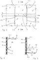
- Fig. 1 shows a generic dam comprising a main body 10, for example made of roller and compacted concrete or of fill material, or other types of material, which extends between the slopes of two mountains.
- the main body 10 of the dam on the upstream side into contact with the water contained in the basin, is provided with a waterproof sheathing comprising, for example, a plurality of sheets 11 of elastically deformable synthetic or bituminous material; the sheets 11 are applied to the surface of the dam 10 maintaining the side edges 12 partially overlapping, and then sealingly connected together, for example, thermally sealed, by ultrasonic method, chemically, or in any other suitable way, and mechanically secured to the main body 10 of the dam.
- a waterproof sheathing comprising, for example, a plurality of sheets 11 of elastically deformable synthetic or bituminous material; the sheets 11 are applied to the surface of the dam 10 maintaining the side edges 12 partially overlapping, and then sealingly connected together, for example, thermally sealed, by ultrasonic method, chemically, or in any
- the sheets 11 can be secured by any known means, for example by providing suitable structural steel sections which enable them to be tensioned or stretched, as described for example in US 5 720 576 ; or by means of a plurality of pins 14 ( fig. 3 ) as shown and described in US 4 915 542 , or in any other appropriate way.
- Reference 13 in figures 1 and 2 has been used to indicate a one-way valve device for draining off the water which has seeped from the main body 10 of the dam between the front surface of the dam body and the rear side of the waterproof sheathing provided by the assembly of sheets 11.
- the sheets 11 of synthetic material can be placed in direct contact with the surface to be waterproofed.
- a layer 15 of draining material can be disposed between the sheets 11 and the front surface of the hydraulic structure, for example a geonet, a geospacer or the like, as shown in figures 4 and 5 .
- the sheets 11 of waterproof material can in turn be in the form of a geocomposite, comprising a layer of waterproof material, coupled to a geotextile, in a per se known way, provided they are suitable for the intended use.
- a one-way drainage valve device 13 as an application in the method according to the invention, and its working are explained in greater detail hereunder, with reference to figures 3, 4 and 5 .
- the one-way drainage valve device 13 is obtained directly during the formation of the waterproof sheathing.
- the fore transversal edge 11a of one sheet 11.1 partially overlaps the rear transversal edge 11b of the adjacent sheet 11.2, for a space "d" of a pre-established length, for example ranging from 5 to 300 cm, preferably from 20 to 150 cm.
- the overlapped side edges 12 of the juxtaposed sheets will be sealed together, and subsequently secured by means of pins 14, or in any other way.
- the overlapped transversal edges 11a and 11b of the two sheets 11.1 and 11.2 which define a one-way drainage valve device of the geomembrane type can extend along part or along the entire width of the sheets, as shown.
- the length "d" of the edges overlapped between two adjacent sheets, and the width of the geomembrane valve device 13 must be such as to enable the efficient operation of the valve thus formed.
- the surface freely in contact of the two superposed sheets which constitute the valve device 13 must be of such kind as to provide a seal exclusively by means of the pressure P1 of the water existing upstream or inside the hydraulic structure, as shown in fig. 4 , and to prevent the formation of folds along the edge 11a of the valve, for example by securing the sheets 11 with an appropriate tension. In this way a wide outflow aperture is obtained for the downflow of the water, in the open condition of the valve device shown in fig.
- valve device 13 will operate in the same way, each time the differential pressure P1-P2 is negative, that is to say, each time the pressure P2 is higher than the hydrostatic pressure P1 existing at the level L3 of the valve 13, as schematically indicated in fig. 5 of the accompanying drawings.
- a drainage device which uses a geomembrane-type single-acting water discharge valve according to the invention, in addition to being simple and inexpensive, is operatively extremely reliable over time, without requiring any substantial maintenance.
- the invention is applicable to any type of waterproof sheathing of elastically deformable synthetic or bituminous material, best results are obtained by using highly flexible plastic materials in sheets.
- the material used for the geomembrane constituting the waterproof sheathing and/or the drainage valve device can be of any kind whatsoever, provided it is suitable for the intended purpose; in particular, it can be chosen from among synthetic and bituminous materials in the following table, taken either individually or in combination.
- the geomembranes may be of a thickness ranging from 0.2 to 60 mm, with a modulus of elasticity ranging from 10 to 5,000 MPa.
- Figures 6 and 7 show a one-way valve device 13 of the membrane type, which can be achieved either at the time of installation of the waterproof sheathing, as in the previous case, or subsequentially with the waterproof sheathing already applied, wherein a cross-cut or elongated aperture 20 is made in one sheet 11 of the waterproof sheathing, in a direction transversal to the downflow direction of the seeped water, indicated by the arrow W.
- a sheet M of elastically deformable synthetic or bituminous material defining a flat valving member is superimposed to the cut 20; the sheet M is sealingly connected, i.e. thermally sealed to the waterproof sheet 11, along three edges 21, leaving the fore edge 22 of the sheet M parallel to the cut 20, extending downstream with respect to the downflow direction W, to freely flex and rise under the thrust of the water which tends to flow downwards by gravity, as shown by the broken line indicated by reference M' in fig. 7 .
- a one-way valve device 13 of geomembrane type is obtained, which can be applied to the waterproof sheathing of any hydraulic structure, dam, canal, hydraulic tunnel, reservoir or the like, for draining off the water that has seeped behind and in which the pressure of the water at upstream side or which flows in the hydraulic tunnel or in the canal, maintains the valve device 13 constantly closed by pressing the flat valving member M against the underlying sheet 11, allowing it to open exclusively when the pressure on the rear side of the flat valving member M exceeds that of the water on the front side.
- the waterproof sheathing provided by sheets 11 of flexible synthetic material can be installed directly in contact with the surface of the hydraulic structure to be waterproofed; conversely, a drainage layer can be positioned between the facing surfaces of the hydraulic structure and the sheets 11 of the waterproof sheathing, consisting for example of a geonet, or in any case by a draining element as indicated by reference 23 in fig. 7 .
- a rigid supporting element 24 for example made by a plate of stiff PVC, HDPE, metal or concrete, in correspondence with the valve device 13, making a cut or an aperture 25 in the element 24 in correspondence with the cut or aperture 20 in the waterproof sheet 11.
- the supporting element 24 must be able to comply with, smooth out or even eliminate the roughness of the surface to be protected, providing a smooth surface on which the waterproof sheathing or geomembrane may rest.
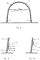
- Figures 8, 9 and 10 show, also by way of example, the formation of valve devices 13 on the waterproof sheathing 30 of the body of a hydraulic tunnel 31.
- the waterproof sheathing 30 comprises a plurality of sheets 11 of elastically deformable synthetic material, disposed in a transversal or longitudinal direction to the tunnel, always taking care to overlap the edges as shown in fig. 1 , which are sealed and secured by means of a plurality of anchoring pins, not shown, or in any other suitable way.
- one-way drainage valve devices 13 are provided, in the way described previously, as schematically shown in the enlarged detail of fig. 9 , where the same numerical references as the preceding examples have been used to indicate similar or equivalent parts.
- FIG. 11 shows the use of a drainage valve device 13 in the waterproof sheathing 40 on the body at the bottom 41 of a canal.
- the drainage valve device 13 can be made in the two ways previously described, or in any other similar way, that it is say by simply overlapping the transversal edges 11a and 11b of two consecutive waterproof sheets 11.1 and 11.2, as shown in the case of fig. 3 , or by a transversal cut in a sheet 11 according to the example of the preceding fig. 6 .
- the drainage valve device 13 is shown, with the continuous line in the closed condition due to the pressure of the water which flows in the canal, in the direction indicated by the arrow W, while with the broken line it is shown in the open condition, for example due to the absence of water in the canal, or whenever the pressure P2 of the water which has seeped between the bottom of the canal and the sheets 11 of waterproof sheathing, exceeds the pressure P1 of the water flowing into the same canal.
- Fig. 13 shows a solution similar to that of fig. 12 in which use has been made of at least one gasket 42 secured to the sheet 11.2, in a back position from its edge, consisting for example of a strip of a foamed synthetic material of the closed cell type to improve sealing of and closure of the one-way valve.
- fig. 14 shows the application of a drainage valve device 13, in a waterproof sheathing 50 in correspondence with a joint 51, or a crack between the bodies of two wall parts 52a and 52b of a hydraulic structure.
- references 11.1 and 11.2 have been used to indicate two sheets of waterproof material, secured along the longitudinal edges 53, 54 on either side of the joint 51, for example as described in EP 1 157 168 , or in any other way.
- the opposite transversal edges 11a and 11b of the two sheets 11.1 and 11.2 are overlapped for a space of a pre-established length, leaving the edge 11a of the upper sheet 11.1 free to flex, to open and close the flat valving member M of the valve device 13 under the differential pressure of the water, in the way previously described; obviously, other modifications and/or applications of the waterproofing and drainage system by means of one-way valve devices are possible, compared to those shown.
- the drainage valve device 13 could initially be closed also on the fore side, in order to prevent infiltration of water during the filling of the hydraulic structure, or whenever the level of the water tends to rise.
- the closure on the free side of the valve device 13 can be obtained by means of a weak seal S, or adhesive tape, an additional strip of geomembrane or in any other suitable way to create a weakened breakage line when the pressure of the water on the rear side tends to exceed a certain value.
- the overlap "d" of the previous cases can be avoided by creating a simple cut along a line transversal to the moving or outflow direction of the water, as in fig. 6 , and subsequently covering such cut with a weaker geomembrane, of a more limited thickness than that of the underlying geomembrane, sealing it on all four sides.
- a weaker geomembrane of a more limited thickness than that of the underlying geomembrane, sealing it on all four sides.
- the overlying weaker geomembrane sheet becomes a sort of "fuse” whose rupture would occur in the event of the hydraulic structure emptying out, or in the event of a decrease in the water level, with consequent exposure of the cut, thereby creating a drainage valve device 13.
Landscapes
- Engineering & Computer Science (AREA)
- General Engineering & Computer Science (AREA)
- Structural Engineering (AREA)
- Mechanical Engineering (AREA)
- Civil Engineering (AREA)
- Environmental & Geological Engineering (AREA)
- Ocean & Marine Engineering (AREA)
- Agronomy & Crop Science (AREA)
- Life Sciences & Earth Sciences (AREA)
- Lining And Supports For Tunnels (AREA)
- Building Environments (AREA)
- Application Of Or Painting With Fluid Materials (AREA)
- Switches Operated By Changes In Physical Conditions (AREA)
- Underground Structures, Protecting, Testing And Restoring Foundations (AREA)
- Soil Working Implements (AREA)
- Investigation Of Foundation Soil And Reinforcement Of Foundation Soil By Compacting Or Drainage (AREA)
Priority Applications (17)
| Application Number | Priority Date | Filing Date | Title |
|---|---|---|---|
| PT50255330T PT1790776T (pt) | 2005-11-23 | 2005-11-23 | Método para impermeabilizar e drenar para fora água infiltrada em estruturas hidráulicas |
| SI200532084A SI1790776T1 (sl) | 2005-11-23 | 2005-11-23 | Postopek za hidroizolacijo in drenažo infiltrirane vode v hidravličnih objektih |
| ES05025533.0T ES2589785T3 (es) | 2005-11-23 | 2005-11-23 | Método para la impermeabilización y drenaje de agua infiltrada en estructuras hidráulicas |
| EP05025533.0A EP1790776B1 (en) | 2005-11-23 | 2005-11-23 | Method for waterproofing and draining off infiltrated water in hydraulic structures |
| DO2006P000255A DOP2006000255A (es) | 2005-11-23 | 2006-11-16 | "metodo y sistema para impermeabilizar y hacer correr el agua infiltrada en estructuras hudraulicas". |
| US12/094,606 US7614826B2 (en) | 2005-11-23 | 2006-11-22 | Method and device for waterproofing and draining off infiltrated water in hydraulic structures |
| AU2006316915A AU2006316915B2 (en) | 2005-11-23 | 2006-11-22 | Method and device for waterproofing and draining off infiltrated water in hydraulic structures |
| MX2008006224A MX2008006224A (es) | 2005-11-23 | 2006-11-22 | Metodo y dispositivo para impermeabilizar y hacer correr el agua infiltrada en estructuras hidraulicas. |
| PCT/EP2006/011163 WO2007059924A1 (en) | 2005-11-23 | 2006-11-22 | Method and system for waterproofing and draining off infiltrated water in hydraulic structures |
| RU2008125157/21A RU2418910C2 (ru) | 2005-11-23 | 2006-11-22 | Способ и устройство для гидроизоляции и слива воды, проникающей в гидротехническое сооружение |
| BRPI0620539-9A BRPI0620539A2 (pt) | 2005-11-23 | 2006-11-22 | método e sistema para a impermeabilização e drenagem de água de infiltração em construções hidráulicas |
| CA2630264A CA2630264C (en) | 2005-11-23 | 2006-11-22 | Method and device for waterproofing and draining off infiltrated water in hydraulic structures |
| PE2006001497A PE20070743A1 (es) | 2005-11-23 | 2006-11-23 | Metodo y sistema para impermeabilizar y hacer correr el agua infiltrada en estructuras hidraulicas |
| TNP2008000230A TNSN08230A1 (en) | 2005-11-23 | 2008-05-21 | Method and system for waterproofing and draining off infiltrated water in hydraulic structures |
| MA31017A MA30040B1 (fr) | 2005-11-23 | 2008-06-11 | Procede et systeme d'etancheite a l'eau et de drainage de l'eau infiltree dans des structures |
| EC2008008537A ECSP088537A (es) | 2005-11-23 | 2008-06-16 | Método y dispositivo para impermeabilizar y hacer correr el agua infiltrada en estructuras hidráulicas |
| HRP20160898TT HRP20160898T1 (hr) | 2005-11-23 | 2016-07-19 | Postupak za hidroizolaciju i drenažu infiltrirane vode u hidrotehničkim objektima |
Applications Claiming Priority (1)
| Application Number | Priority Date | Filing Date | Title |
|---|---|---|---|
| EP05025533.0A EP1790776B1 (en) | 2005-11-23 | 2005-11-23 | Method for waterproofing and draining off infiltrated water in hydraulic structures |
Publications (2)
| Publication Number | Publication Date |
|---|---|
| EP1790776A1 EP1790776A1 (en) | 2007-05-30 |
| EP1790776B1 true EP1790776B1 (en) | 2016-04-27 |
Family
ID=36218491
Family Applications (1)
| Application Number | Title | Priority Date | Filing Date |
|---|---|---|---|
| EP05025533.0A Active EP1790776B1 (en) | 2005-11-23 | 2005-11-23 | Method for waterproofing and draining off infiltrated water in hydraulic structures |
Country Status (17)
| Country | Link |
|---|---|
| US (1) | US7614826B2 (es) |
| EP (1) | EP1790776B1 (es) |
| AU (1) | AU2006316915B2 (es) |
| BR (1) | BRPI0620539A2 (es) |
| CA (1) | CA2630264C (es) |
| DO (1) | DOP2006000255A (es) |
| EC (1) | ECSP088537A (es) |
| ES (1) | ES2589785T3 (es) |
| HR (1) | HRP20160898T1 (es) |
| MA (1) | MA30040B1 (es) |
| MX (1) | MX2008006224A (es) |
| PE (1) | PE20070743A1 (es) |
| PT (1) | PT1790776T (es) |
| RU (1) | RU2418910C2 (es) |
| SI (1) | SI1790776T1 (es) |
| TN (1) | TNSN08230A1 (es) |
| WO (1) | WO2007059924A1 (es) |
Families Citing this family (18)
| Publication number | Priority date | Publication date | Assignee | Title |
|---|---|---|---|---|
| IT1392652B1 (it) * | 2008-09-11 | 2012-03-16 | Carpi Tech Bv Amsterdam Chiasso Branch | Metodo e sistema per il fissaggio di membrane impermeabili ad opere idrauliche |
| NZ596720A (en) * | 2009-04-28 | 2013-05-31 | Infrastructure Technologies Ltd | CHANNEL AND WATER STORAGE LINER using ethylene vinyl acetate copolymer and cementius composition |
| US8702345B2 (en) * | 2010-09-09 | 2014-04-22 | Allen Leroy Stein | Modular, dynamically sized and shaped, industrial-liquid-containment system and methods of use |
| IT1402028B1 (it) * | 2010-10-14 | 2013-08-28 | Gsi Geosyntec Invest B V | Metodo e dispositivo per il drenaggio di acqua infiltrata in strutture idrauliche. |
| US20130259576A1 (en) * | 2010-11-30 | 2013-10-03 | Jps Industries, Inc. | Erosion barrier method and apparatus |
| CN103243681A (zh) * | 2013-05-16 | 2013-08-14 | 黄河勘测规划设计有限公司 | 土石坝防渗用土工膜与混凝土建筑之间的柔性连接方法 |
| CN103526724B (zh) * | 2013-10-25 | 2016-03-30 | 中国电建集团中南勘测设计研究院有限公司 | 一种水库库底土工膜与库周排水廊道周边缝连接的锚固防渗结构 |
| US20170044732A1 (en) * | 2014-04-24 | 2017-02-16 | Carpi Tech B.V. | Method And System For Anchoring A Waterproofing Liner To Concrete Curbs Of A Hydraulic Structure |
| CN106996093A (zh) * | 2016-01-26 | 2017-08-01 | 北京市水利规划设计研究院 | 土工膜锚固结构以及锚固方法 |
| RU2675497C1 (ru) * | 2017-02-07 | 2018-12-19 | Федеральное Государственное Бюджетное Образовательное Учреждение Высшего Образования "Донской Государственный Аграрный Университет" (Фгбоу Во Дгау) | Способ дренирования геокомпозитных матов |
| CN108505501B (zh) * | 2018-05-31 | 2024-01-30 | 山东农业大学 | 水利土木工程单向排水排气阀及其布置方法 |
| CN109056657B (zh) * | 2018-09-14 | 2024-06-25 | 山东省水利科学研究院 | 一种可控逆止排水阀 |
| CN109356118A (zh) * | 2018-11-21 | 2019-02-19 | 中国电建集团成都勘测设计研究院有限公司 | 水位变幅区挡排水结构 |
| CN109594570A (zh) * | 2018-12-06 | 2019-04-09 | 贵阳铝镁设计研究院有限公司 | 滤饼干法赤泥堆场边坡排水结构及施工方法 |
| CN109826084A (zh) * | 2019-02-21 | 2019-05-31 | 广东省水利水电科学研究院 | 一种渡槽渗漏修复方法 |
| CN110453645A (zh) * | 2019-08-28 | 2019-11-15 | 枣庄学院 | 一种维持库水型滑坡稳定性的装配型定向透水式止水帷幕 |
| JP2021116543A (ja) * | 2020-01-23 | 2021-08-10 | 東洋紡株式会社 | 土木用複合シート |
| CN113322904B (zh) * | 2021-06-04 | 2022-08-19 | 中国电建集团成都勘测设计研究院有限公司 | 用于覆盖层地基混凝土坝的高喷防渗墙及其施工方法 |
Citations (3)
| Publication number | Priority date | Publication date | Assignee | Title |
|---|---|---|---|---|
| JP2000337537A (ja) * | 1999-05-26 | 2000-12-05 | San Buresu:Kk | 止水シート用逆止弁 |
| JP2000352033A (ja) * | 1999-06-14 | 2000-12-19 | Cosmo Koki Co Ltd | 逆止弁付き防水シート |
| JP2003055935A (ja) * | 2001-08-10 | 2003-02-26 | Teratekku:Kk | 外水圧対策兼備の土木用遮水シート布設工法 |
Family Cites Families (11)
| Publication number | Priority date | Publication date | Assignee | Title |
|---|---|---|---|---|
| US1802714A (en) * | 1928-06-29 | 1931-04-28 | Skelton D Henry | Means for protecting dams |
| US3854292A (en) | 1971-09-30 | 1974-12-17 | H Nienstadt | Irrigation ditch liner and method for making same |
| DE2734514C2 (de) | 1977-07-30 | 1984-02-02 | Wayss & Freytag Ag, 6000 Frankfurt | Fugenkonstruktion für die Bewegungsfuge im Anschlußbereich der Wand an die Sohle eines vorgespannten Flüssigkeitsbehälters aus Beton |
| IT1188780B (it) | 1979-03-27 | 1988-01-28 | Pirelli Furlanis | Rivestimento impermeabilizzante per contenitori di liquidi |
| ES8507218A1 (es) | 1984-11-16 | 1985-08-16 | Gordun Burillo Fernando | Un procedimiento de impermeabilizacion de superficies, de especial aplicacion a las superficies interiores de tuneles, canales y mineria |
| FR2599400B1 (fr) | 1986-06-03 | 1991-04-05 | Ledeuil Didier | Procede pour rendre etanche a l'eau une structure hydraulique en beton compacte ou en remblais |
| IT1248825B (it) * | 1990-05-29 | 1995-01-30 | Sibelon Srl | Metodo per la protezione di dighe, con disidratazione per condensazione e drenaggio, non in pressione, dell`acqua presente nel corpo diga. |
| IT1272902B (it) * | 1995-01-13 | 1997-07-01 | Sibelon Srl | Sistema per formare sott'acqua rivestimenti impermeabili protettivi di opere idrauliche |
| IT1279074B1 (it) | 1995-11-24 | 1997-12-04 | Sibelon Srl | Sistema per la realizzazione di impermeabilizzazioni di opere idrauliche con fogli rigidi in materiale sintetico |
| IT1304092B1 (it) | 1998-12-10 | 2001-03-07 | Sibelon Srl | Metodo per l'impermeabilizzazione di giunti e/o di fessurazioni inopere idrauliche e strutture in calcestruzzo e/o in muratura |
| DE10127493A1 (de) * | 2001-06-01 | 2002-12-05 | Heinz Steffen | Verfahren zur Sicherung von Staudämmen und Kunststoffdichtungsbahn |
-
2005
- 2005-11-23 SI SI200532084A patent/SI1790776T1/sl unknown
- 2005-11-23 EP EP05025533.0A patent/EP1790776B1/en active Active
- 2005-11-23 PT PT50255330T patent/PT1790776T/pt unknown
- 2005-11-23 ES ES05025533.0T patent/ES2589785T3/es active Active
-
2006
- 2006-11-16 DO DO2006P000255A patent/DOP2006000255A/es unknown
- 2006-11-22 AU AU2006316915A patent/AU2006316915B2/en not_active Ceased
- 2006-11-22 WO PCT/EP2006/011163 patent/WO2007059924A1/en active Application Filing
- 2006-11-22 BR BRPI0620539-9A patent/BRPI0620539A2/pt active Search and Examination
- 2006-11-22 RU RU2008125157/21A patent/RU2418910C2/ru not_active IP Right Cessation
- 2006-11-22 CA CA2630264A patent/CA2630264C/en not_active Expired - Fee Related
- 2006-11-22 MX MX2008006224A patent/MX2008006224A/es active IP Right Grant
- 2006-11-22 US US12/094,606 patent/US7614826B2/en not_active Expired - Fee Related
- 2006-11-23 PE PE2006001497A patent/PE20070743A1/es not_active Application Discontinuation
-
2008
- 2008-05-21 TN TNP2008000230A patent/TNSN08230A1/en unknown
- 2008-06-11 MA MA31017A patent/MA30040B1/fr unknown
- 2008-06-16 EC EC2008008537A patent/ECSP088537A/es unknown
-
2016
- 2016-07-19 HR HRP20160898TT patent/HRP20160898T1/hr unknown
Patent Citations (3)
| Publication number | Priority date | Publication date | Assignee | Title |
|---|---|---|---|---|
| JP2000337537A (ja) * | 1999-05-26 | 2000-12-05 | San Buresu:Kk | 止水シート用逆止弁 |
| JP2000352033A (ja) * | 1999-06-14 | 2000-12-19 | Cosmo Koki Co Ltd | 逆止弁付き防水シート |
| JP2003055935A (ja) * | 2001-08-10 | 2003-02-26 | Teratekku:Kk | 外水圧対策兼備の土木用遮水シート布設工法 |
Also Published As
| Publication number | Publication date |
|---|---|
| TNSN08230A1 (en) | 2009-10-30 |
| PT1790776T (pt) | 2016-07-27 |
| US20080298896A1 (en) | 2008-12-04 |
| US7614826B2 (en) | 2009-11-10 |
| CA2630264A1 (en) | 2007-05-31 |
| AU2006316915B2 (en) | 2011-09-08 |
| DOP2006000255A (es) | 2007-11-30 |
| HRP20160898T1 (hr) | 2016-09-23 |
| ES2589785T3 (es) | 2016-11-16 |
| CA2630264C (en) | 2015-01-20 |
| RU2008125157A (ru) | 2009-12-27 |
| BRPI0620539A2 (pt) | 2011-11-16 |
| ECSP088537A (es) | 2008-07-30 |
| MA30040B1 (fr) | 2008-12-01 |
| AU2006316915A1 (en) | 2007-05-31 |
| WO2007059924A1 (en) | 2007-05-31 |
| MX2008006224A (es) | 2008-12-03 |
| RU2418910C2 (ru) | 2011-05-20 |
| SI1790776T1 (sl) | 2016-09-30 |
| PE20070743A1 (es) | 2007-07-26 |
| EP1790776A1 (en) | 2007-05-30 |
Similar Documents
| Publication | Publication Date | Title |
|---|---|---|
| EP1790776B1 (en) | Method for waterproofing and draining off infiltrated water in hydraulic structures | |
| EP0722016B1 (en) | Method for constructing an impermeable protective membrane underwater on a hydraulic structure | |
| US6126362A (en) | Pressure secured liquid damming protective bank device and method | |
| HRP20010434A2 (en) | Embankment dam and waterproofing method | |
| CA2262424A1 (en) | Foundation wall construction | |
| CN112813920A (zh) | 一种防止堤防和土坝漫顶破坏的应急抢险装置及施工方法 | |
| WO2012049269A1 (en) | Method and device for draining off water seeped in a soil underlying hydraulic structures | |
| JP2001212538A (ja) | 遮水シートの敷設構造及び遮水シートの敷設方法 | |
| JP5109581B2 (ja) | 水利構造物の逆流防止水抜き構造 | |
| CN109914358B (zh) | 疏浚工程的闸箱埋管式排水口结构 | |
| JP3634324B2 (ja) | 砂防ダムにおける堤体仮締め切りスリット設置工法及び同工法に使用するプロテクター | |
| JP2001152425A (ja) | 護岸の遮水構造 | |
| JP2007105618A (ja) | 廃棄物処分場の遮水構造 | |
| WO2012095483A1 (en) | Method and device for laying down and tensioning an impermeable cover for hydraulic works in loose material | |
| WO2000037741A1 (en) | A method and a covering unit for counteracting the penetration of liquid into a mass of earth | |
| JPH11309426A (ja) | 廃棄物処分場における止水シートと遮水壁の接合方法および接合構造 | |
| TH56129B (th) | ระบบและกรรมวิธีสำหรับกันน้ำและระบายน้ำที่แทรกซึมอยู่ในบรรดาโครงสร้างไฮดรอลิก | |
| TH91064A (th) | ระบบและกรรมวิธีสำหรับกันน้ำและระบายน้ำที่แทรกซึมอยู่ในบรรดาโครงสร้างไฮดรอลิก | |
| NZ609811B2 (en) | Method and device for laying down and tensioning an impermeable cover for hydraulic works in loose material |
Legal Events
| Date | Code | Title | Description |
|---|---|---|---|
| PUAI | Public reference made under article 153(3) epc to a published international application that has entered the european phase |
Free format text: ORIGINAL CODE: 0009012 |
|
| AK | Designated contracting states |
Kind code of ref document: A1 Designated state(s): AT BE BG CH CY CZ DE DK EE ES FI FR GB GR HU IE IS IT LI LT LU LV MC NL PL PT RO SE SI SK TR |
|
| AX | Request for extension of the european patent |
Extension state: AL BA HR MK YU |
|
| 17P | Request for examination filed |
Effective date: 20071119 |
|
| AKX | Designation fees paid |
Designated state(s): AT BE BG CH CY CZ DE DK EE ES FI FR GB GR HU IE IS IT LI LT LU LV MC NL PL PT RO SE SI SK TR |
|
| AXX | Extension fees paid |
Extension state: BA Payment date: 20071119 Extension state: MK Payment date: 20071119 Extension state: AL Payment date: 20071119 Extension state: YU Payment date: 20071119 Extension state: HR Payment date: 20071119 |
|
| 17Q | First examination report despatched |
Effective date: 20081111 |
|
| GRAP | Despatch of communication of intention to grant a patent |
Free format text: ORIGINAL CODE: EPIDOSNIGR1 |
|
| INTG | Intention to grant announced |
Effective date: 20151120 |
|
| GRAS | Grant fee paid |
Free format text: ORIGINAL CODE: EPIDOSNIGR3 |
|
| GRAA | (expected) grant |
Free format text: ORIGINAL CODE: 0009210 |
|
| RAP1 | Party data changed (applicant data changed or rights of an application transferred) |
Owner name: CARPI TECH B.V. |
|
| AK | Designated contracting states |
Kind code of ref document: B1 Designated state(s): AT BE BG CH CY CZ DE DK EE ES FI FR GB GR HU IE IS IT LI LT LU LV MC NL PL PT RO SE SI SK TR |
|
| AX | Request for extension of the european patent |
Extension state: AL BA HR MK YU |
|
| REG | Reference to a national code |
Ref country code: GB Ref legal event code: FG4D |
|
| REG | Reference to a national code |
Ref country code: CH Ref legal event code: EP |
|
| REG | Reference to a national code |
Ref country code: AT Ref legal event code: REF Ref document number: 794977 Country of ref document: AT Kind code of ref document: T Effective date: 20160515 |
|
| REG | Reference to a national code |
Ref country code: IE Ref legal event code: FG4D |
|
| REG | Reference to a national code |
Ref country code: DE Ref legal event code: R096 Ref document number: 602005049137 Country of ref document: DE |
|
| REG | Reference to a national code |
Ref country code: HR Ref legal event code: TUEP Ref document number: P20160898 Country of ref document: HR |
|
| REG | Reference to a national code |
Ref country code: RO Ref legal event code: EPE Ref country code: PT Ref legal event code: SC4A Ref document number: 1790776 Country of ref document: PT Date of ref document: 20160727 Kind code of ref document: T Free format text: AVAILABILITY OF NATIONAL TRANSLATION Effective date: 20160719 |
|
| REG | Reference to a national code |
Ref country code: SE Ref legal event code: TRGR |
|
| REG | Reference to a national code |
Ref country code: LT Ref legal event code: MG4D |
|
| REG | Reference to a national code |
Ref country code: NL Ref legal event code: MP Effective date: 20160427 |
|
| REG | Reference to a national code |
Ref country code: HR Ref legal event code: T1PR Ref document number: P20160898 Country of ref document: HR |
|
| PG25 | Lapsed in a contracting state [announced via postgrant information from national office to epo] |
Ref country code: NL Free format text: LAPSE BECAUSE OF FAILURE TO SUBMIT A TRANSLATION OF THE DESCRIPTION OR TO PAY THE FEE WITHIN THE PRESCRIBED TIME-LIMIT Effective date: 20160427 |
|
| PG25 | Lapsed in a contracting state [announced via postgrant information from national office to epo] |
Ref country code: LT Free format text: LAPSE BECAUSE OF FAILURE TO SUBMIT A TRANSLATION OF THE DESCRIPTION OR TO PAY THE FEE WITHIN THE PRESCRIBED TIME-LIMIT Effective date: 20160427 Ref country code: PL Free format text: LAPSE BECAUSE OF FAILURE TO SUBMIT A TRANSLATION OF THE DESCRIPTION OR TO PAY THE FEE WITHIN THE PRESCRIBED TIME-LIMIT Effective date: 20160427 Ref country code: FI Free format text: LAPSE BECAUSE OF FAILURE TO SUBMIT A TRANSLATION OF THE DESCRIPTION OR TO PAY THE FEE WITHIN THE PRESCRIBED TIME-LIMIT Effective date: 20160427 |
|
| REG | Reference to a national code |
Ref country code: FR Ref legal event code: PLFP Year of fee payment: 12 |
|
| REG | Reference to a national code |
Ref country code: ES Ref legal event code: FG2A Ref document number: 2589785 Country of ref document: ES Kind code of ref document: T3 Effective date: 20161116 |
|
| PG25 | Lapsed in a contracting state [announced via postgrant information from national office to epo] |
Ref country code: LV Free format text: LAPSE BECAUSE OF FAILURE TO SUBMIT A TRANSLATION OF THE DESCRIPTION OR TO PAY THE FEE WITHIN THE PRESCRIBED TIME-LIMIT Effective date: 20160427 |
|
| REG | Reference to a national code |
Ref country code: DE Ref legal event code: R097 Ref document number: 602005049137 Country of ref document: DE |
|
| PG25 | Lapsed in a contracting state [announced via postgrant information from national office to epo] |
Ref country code: EE Free format text: LAPSE BECAUSE OF FAILURE TO SUBMIT A TRANSLATION OF THE DESCRIPTION OR TO PAY THE FEE WITHIN THE PRESCRIBED TIME-LIMIT Effective date: 20160427 Ref country code: SK Free format text: LAPSE BECAUSE OF FAILURE TO SUBMIT A TRANSLATION OF THE DESCRIPTION OR TO PAY THE FEE WITHIN THE PRESCRIBED TIME-LIMIT Effective date: 20160427 Ref country code: DK Free format text: LAPSE BECAUSE OF FAILURE TO SUBMIT A TRANSLATION OF THE DESCRIPTION OR TO PAY THE FEE WITHIN THE PRESCRIBED TIME-LIMIT Effective date: 20160427 |
|
| REG | Reference to a national code |
Ref country code: GR Ref legal event code: EP Ref document number: 20160401771 Country of ref document: GR Effective date: 20161020 |
|
| PLBE | No opposition filed within time limit |
Free format text: ORIGINAL CODE: 0009261 |
|
| STAA | Information on the status of an ep patent application or granted ep patent |
Free format text: STATUS: NO OPPOSITION FILED WITHIN TIME LIMIT |
|
| 26N | No opposition filed |
Effective date: 20170130 |
|
| PG25 | Lapsed in a contracting state [announced via postgrant information from national office to epo] |
Ref country code: LU Free format text: LAPSE BECAUSE OF NON-PAYMENT OF DUE FEES Effective date: 20161130 |
|
| REG | Reference to a national code |
Ref country code: FR Ref legal event code: PLFP Year of fee payment: 13 |
|
| REG | Reference to a national code |
Ref country code: HR Ref legal event code: ODRP Ref document number: P20160898 Country of ref document: HR Payment date: 20171116 Year of fee payment: 13 |
|
| PGFP | Annual fee paid to national office [announced via postgrant information from national office to epo] |
Ref country code: FR Payment date: 20171024 Year of fee payment: 13 Ref country code: DE Payment date: 20171025 Year of fee payment: 13 Ref country code: RO Payment date: 20171113 Year of fee payment: 13 Ref country code: TR Payment date: 20171114 Year of fee payment: 13 Ref country code: CZ Payment date: 20171109 Year of fee payment: 13 |
|
| REG | Reference to a national code |
Ref country code: AT Ref legal event code: UEP Ref document number: 794977 Country of ref document: AT Kind code of ref document: T Effective date: 20160427 |
|
| PGFP | Annual fee paid to national office [announced via postgrant information from national office to epo] |
Ref country code: BE Payment date: 20171122 Year of fee payment: 13 Ref country code: PT Payment date: 20171103 Year of fee payment: 13 Ref country code: IE Payment date: 20171114 Year of fee payment: 13 Ref country code: GR Payment date: 20171123 Year of fee payment: 13 Ref country code: GB Payment date: 20171024 Year of fee payment: 13 Ref country code: AT Payment date: 20171122 Year of fee payment: 13 Ref country code: CH Payment date: 20171122 Year of fee payment: 13 Ref country code: SI Payment date: 20171122 Year of fee payment: 13 Ref country code: SE Payment date: 20171103 Year of fee payment: 13 Ref country code: BG Payment date: 20171124 Year of fee payment: 13 Ref country code: IT Payment date: 20171124 Year of fee payment: 13 |
|
| PGFP | Annual fee paid to national office [announced via postgrant information from national office to epo] |
Ref country code: ES Payment date: 20171218 Year of fee payment: 13 |
|
| PG25 | Lapsed in a contracting state [announced via postgrant information from national office to epo] |
Ref country code: HU Free format text: LAPSE BECAUSE OF FAILURE TO SUBMIT A TRANSLATION OF THE DESCRIPTION OR TO PAY THE FEE WITHIN THE PRESCRIBED TIME-LIMIT; INVALID AB INITIO Effective date: 20051123 Ref country code: CY Free format text: LAPSE BECAUSE OF FAILURE TO SUBMIT A TRANSLATION OF THE DESCRIPTION OR TO PAY THE FEE WITHIN THE PRESCRIBED TIME-LIMIT Effective date: 20160427 |
|
| PG25 | Lapsed in a contracting state [announced via postgrant information from national office to epo] |
Ref country code: MC Free format text: LAPSE BECAUSE OF FAILURE TO SUBMIT A TRANSLATION OF THE DESCRIPTION OR TO PAY THE FEE WITHIN THE PRESCRIBED TIME-LIMIT Effective date: 20160427 Ref country code: IS Free format text: LAPSE BECAUSE OF FAILURE TO SUBMIT A TRANSLATION OF THE DESCRIPTION OR TO PAY THE FEE WITHIN THE PRESCRIBED TIME-LIMIT Effective date: 20160427 |
|
| REG | Reference to a national code |
Ref country code: DE Ref legal event code: R119 Ref document number: 602005049137 Country of ref document: DE |
|
| REG | Reference to a national code |
Ref country code: HR Ref legal event code: PBON Ref document number: P20160898 Country of ref document: HR Effective date: 20181123 |
|
| REG | Reference to a national code |
Ref country code: CH Ref legal event code: PL |
|
| REG | Reference to a national code |
Ref country code: SE Ref legal event code: EUG |
|
| REG | Reference to a national code |
Ref country code: AT Ref legal event code: MM01 Ref document number: 794977 Country of ref document: AT Kind code of ref document: T Effective date: 20181123 |
|
| GBPC | Gb: european patent ceased through non-payment of renewal fee |
Effective date: 20181123 |
|
| PG25 | Lapsed in a contracting state [announced via postgrant information from national office to epo] |
Ref country code: CZ Free format text: LAPSE BECAUSE OF NON-PAYMENT OF DUE FEES Effective date: 20181123 Ref country code: SE Free format text: LAPSE BECAUSE OF NON-PAYMENT OF DUE FEES Effective date: 20181124 Ref country code: PT Free format text: LAPSE BECAUSE OF NON-PAYMENT OF DUE FEES Effective date: 20190523 |
|
| REG | Reference to a national code |
Ref country code: BE Ref legal event code: FP Effective date: 20160720 Ref country code: BE Ref legal event code: MM Effective date: 20181130 |
|
| REG | Reference to a national code |
Ref country code: IE Ref legal event code: MM4A |
|
| PG25 | Lapsed in a contracting state [announced via postgrant information from national office to epo] |
Ref country code: CH Free format text: LAPSE BECAUSE OF NON-PAYMENT OF DUE FEES Effective date: 20181130 Ref country code: BG Free format text: LAPSE BECAUSE OF NON-PAYMENT OF DUE FEES Effective date: 20190531 Ref country code: LI Free format text: LAPSE BECAUSE OF NON-PAYMENT OF DUE FEES Effective date: 20181130 Ref country code: RO Free format text: LAPSE BECAUSE OF NON-PAYMENT OF DUE FEES Effective date: 20181123 Ref country code: SI Free format text: LAPSE BECAUSE OF NON-PAYMENT OF DUE FEES Effective date: 20181124 Ref country code: GR Free format text: LAPSE BECAUSE OF NON-PAYMENT OF DUE FEES Effective date: 20190605 |
|
| REG | Reference to a national code |
Ref country code: SI Ref legal event code: KO00 Effective date: 20190709 |
|
| PG25 | Lapsed in a contracting state [announced via postgrant information from national office to epo] |
Ref country code: FR Free format text: LAPSE BECAUSE OF NON-PAYMENT OF DUE FEES Effective date: 20181130 Ref country code: IT Free format text: LAPSE BECAUSE OF NON-PAYMENT OF DUE FEES Effective date: 20181123 Ref country code: DE Free format text: LAPSE BECAUSE OF NON-PAYMENT OF DUE FEES Effective date: 20190601 Ref country code: AT Free format text: LAPSE BECAUSE OF NON-PAYMENT OF DUE FEES Effective date: 20181123 Ref country code: IE Free format text: LAPSE BECAUSE OF NON-PAYMENT OF DUE FEES Effective date: 20181123 |
|
| PG25 | Lapsed in a contracting state [announced via postgrant information from national office to epo] |
Ref country code: BE Free format text: LAPSE BECAUSE OF NON-PAYMENT OF DUE FEES Effective date: 20181130 |
|
| PG25 | Lapsed in a contracting state [announced via postgrant information from national office to epo] |
Ref country code: GB Free format text: LAPSE BECAUSE OF NON-PAYMENT OF DUE FEES Effective date: 20181123 |
|
| REG | Reference to a national code |
Ref country code: ES Ref legal event code: FD2A Effective date: 20200108 |
|
| PG25 | Lapsed in a contracting state [announced via postgrant information from national office to epo] |
Ref country code: ES Free format text: LAPSE BECAUSE OF NON-PAYMENT OF DUE FEES Effective date: 20181124 |
|
| PG25 | Lapsed in a contracting state [announced via postgrant information from national office to epo] |
Ref country code: TR Free format text: LAPSE BECAUSE OF NON-PAYMENT OF DUE FEES Effective date: 20181123 |