EP1790548A1 - Weichenzungenantriebsvorrichtung - Google Patents
Weichenzungenantriebsvorrichtung Download PDFInfo
- Publication number
- EP1790548A1 EP1790548A1 EP06291797A EP06291797A EP1790548A1 EP 1790548 A1 EP1790548 A1 EP 1790548A1 EP 06291797 A EP06291797 A EP 06291797A EP 06291797 A EP06291797 A EP 06291797A EP 1790548 A1 EP1790548 A1 EP 1790548A1
- Authority
- EP
- European Patent Office
- Prior art keywords
- lever
- control
- control lever
- return lever
- return
- Prior art date
- Legal status (The legal status is an assumption and is not a legal conclusion. Google has not performed a legal analysis and makes no representation as to the accuracy of the status listed.)
- Granted
Links
Images


Classifications
-
- B—PERFORMING OPERATIONS; TRANSPORTING
- B61—RAILWAYS
- B61L—GUIDING RAILWAY TRAFFIC; ENSURING THE SAFETY OF RAILWAY TRAFFIC
- B61L5/00—Local operating mechanisms for points or track-mounted scotch-blocks; Visible or audible signals; Local operating mechanisms for visible or audible signals
- B61L5/02—Mechanical devices for operating points or scotch-blocks, e.g. local manual control
Definitions
- the present invention relates to a railroad switching blades maneuvering device.
- the switches for transferring a convoy to one or other of two alternative routes comprise movable rail elements called needle blades. Following the selected path, one of the needle blades is applied to one of the fixed rails, called counter rail, of the track to allow the deviation of the convoy. On the contrary, the other needle blade is separated from the associated fixed rail.
- these movable elements of the switches are moved by a single and autonomous actuating mechanism forming an actuator.
- the latter is connected to the moving needle blades by a set of rods forming a linkage.
- the needle blades are linked to the operating mechanism by a linkage which is linked to the needle blades at several points spaced along the length of the needle blades.
- the operating mechanism is installed along the track in the vicinity of the tip of the needle blades, that is to say in the vicinity of their free end.
- a succession of long rods are arranged following each other along the track to form the linkage. These rods are connected to each other by means of maneuvering the needle blades.
- These operating devices form corner references connected, on the one hand, to the successive rods extending along the track and, on the other hand, to transverse control rods arranged perpendicularly to the track and on which are connected the needle blades to be moved.
- the rods arranged along the track are relatively long and are subject to expansion phenomena during changes in ambient temperature. Under the effect of reducing or increasing the length of these rods, the operating devices to which the transverse control rods are connected are actuated, which causes displacements of the needle blades and unintentional adjustments of the position of these blades. These maladjustments can cause failures in the operation of the railway network.
- This document describes a device equipped with a return lever provided with a fork adapted to cooperate with a roller carried by a control bar integrated in the linkage.
- the roller is contained in the fork to ensure the normal operation of the return lever and therefore the needle blade.
- the roller escapes from the fork, avoiding the drive of the return lever and therefore of the needle blade.
- This device is very difficult to produce industrially, especially for controlling the needle blade where it is movable only on a short stroke, since some components must then withstand very high forces which requires that these constituents are very robust and so very bulky.
- the object of the invention is to propose a switching control device that is easy to make and compact.
- the subject of the invention is a device for maneuvering the needle blades of a switch, characterized in that the control member comprises a control lever articulated with respect to the base and comprising a connecting arm with an actuator for its drive, which control lever is adapted to cooperate with the return lever for driving the return lever under the action of the actuator on said at least a median portion of the travel stroke of the lever of ordered.
- the invention also relates to a switch comprising at least one movable needle blade and an operating device connected to an operating mechanism, characterized in that it comprises an operating device as defined above interposed between the operating mechanism and the or each switching blade.
- FIG. 1 diagrammatically shows a switch 10. This is suitable for connecting a first channel 12 provided at one end alternatively with two lanes 14, 16 provided at the other end of the switch.
- the switch has two outer fixed rails, one, 18, generally rectilinear and the other, 20, generally curved. Between these two fixed rails are arranged movable needle blades 22, 24 adapted to be applied along the fixed rails respectively 18 and 20. These needle blades are bevelled towards their points 22A, 24A. At their other end, denoted 22B, 24B, the needle blades are connected in the extension of fixed rails, not shown, of the two channels 14, 16. This end forms the heel of the needle blades.
- the switch 10 is associated with an installation for maneuvering the needle blades.
- This comprises an actuator consisting of an operating mechanism 30, a linkage 32 extending generally along the switch over most of the length of the needle blades and transverse control rods 33 connected to the linkage 32 with regular spaces and connected to the needle blades 22 and 24.
- the linkage 32 is connected to the actuating mechanism 30 for its actuation.
- the operating mechanism 30 is fixed in point relative to the track on the side of the track 12 in the vicinity of the points 22A, 24A of the needle blades.
- This operating mechanism is formed for example of an electromechanical actuator.
- the linkage 32 comprises a succession of longitudinal rods 34 connected in series with each other by operating devices 36 interposed between two longitudinal rods 34.
- the operating mechanism 30 is connected to one end of the linkage 32.
- the operating devices 36 are distributed along the length of the needle blades being separated from each other for example by a distance of 2 m to 7 m.
- One or more successive rods 34 connects two successive operating devices.
- an inverter 38 is disposed between two successive actuators.
- the transverse control rods 33 are each connected to an output of an operating device 36.
- It comprises essentially a base 40, a control lever 42 integrated in the linkage 32 between two successive rods and a movable return member 44 formed of a lever hinged relative to the base 40.
- the base 40 comprises a plate 46 for fixing the operating device to the ground, for example at the end of a crosspiece of the switch, and a housing 48 inside which the control lever 42 and the return lever 44 are partially arranged.
- the control lever 42 is articulated around a Y-Y axis parallel to the axis of articulation of the return lever 44 noted X-X. It has two arms arranged parallel to each other, one above the other and extending on the same side of the Y-axis.
- One of the arms 49 forming a connecting arm to the linkage 32 extends outside the housing 48. At its free end 49A, two successive rods of the linkage 32 are hinged about an axis Y1-Y1.
- the second arm 50 forming a coupling arm is formed of a trapezoidal general plate flared towards its free end 50A.
- the coupling arm 50 is shorter than the connecting arm 49. It extends into the housing 48.
- the return lever 44 is hinged relative to the base 40 about the generally vertical axis XX extending perpendicularly to the plane of the linkage 32. It comprises a driving arm 54 projecting out of the casing 48 through a lateral slot. At the projecting end noted 56 of the arm 54 is connected a transverse control rod 33 via an elastic connection.
- the return lever 44 further comprises a control arm 58 integral with the drive arm 54.
- the control arm 58 is movable inside the housing 48.
- the return lever 44 has, at its free end, a shape fork assembly defined by two end teeth 60A, 60B spaced from one another and projecting towards the control lever 42.
- the teeth 60A, 60B have, along their generally facing surfaces, cam surfaces 62A, 62B diverging from each other away from the X-X axis. These cam surfaces 62A, 62B are adapted to cooperate with associated cams 64A, 64B carried by the coupling arm 50 of the control lever.
- the counter-cams 64A, 64B are formed by rotary rollers carried by the free end of the coupling arm 50. These rollers are articulated about parallel axes extending parallel to the axes XX and YY. The rollers are offset angularly with respect to the Y-Y axis and are equidistant from it.
- the cam surfaces 62A, 62B are interrupted at the end of the teeth 60A, 60B to allow clearance of the cams 64A, 64B.
- the free ends of the teeth form cylindrical generally cylindrical abutment surfaces 66A, 66B which are generally and respectively concentric with the displacement described by the outside diameter of the two rollers 64A, 64B of the deflection lever 44, being in support or at least facing of one or the other of the counter-cams 64A, 64B.
- a contact 70 is secured to the base 40. It is equipped with a movable feeler finger 72. This contact is able to indicate the position of the operating device. It is for example closed when the feeler finger 72 is released under the action of a spring proper to the contact and open when the probe finger is depressed.
- the control lever 42 and in particular preferably the coupling arm 50 have a cam 73 in an arc having two ends 74A, 74B. It is adapted to push the probe finger when it is traversed along its length and to release it when it reaches its ends 74A, 74B.
- the switch is in a position such that the needle blade 22 is applied against the fixed rail 18, while the needle blade 24 is spaced from the fixed rail 20.
- the mechanism of maneuver 30 is in a first position and thus imposes a first position to the rods 34.
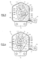
- the operating devices 36 are in the position illustrated in Figure 2B, the control lever 42 being generally moved to the right and the end 56 of the driver arm facing downwards in the figure.
- the control lever 42 is in a first position while the driving arm 54 is in a first extreme position.
- the roller 64A is disposed exactly opposite the end of the tooth 60A, and bears against the abutment surface 66A of the return lever. The roller 64A then forms a stop for the return lever 44, preventing the driver arm 54 from being turned towards the top of the figure. Thus, the needle blades are wedged in the position illustrated in Figure 1.
- control lever 42 is driven by the action of the rods 34 controlled by the operating mechanism 30, as shown by the arrow F in Figure 3.
- the roller 66A then moves to more to be opposite the bearing surface 66A, thus ensuring a release of the return lever 44.
- the feeler finger 72 reaches the end of the cam and rests on the lateral surface
- the roller 64B Upon subsequent movement of the control lever 42 in the direction of the arrow F and, as shown in Figure 4, the roller 64B comes into contact with the cam surface 62B, in the vicinity of the base of the tooth 60B. The roller then leans on this cam surface. In doing so, the roller 64B drives the return lever 44 by tilting it in the opposite direction of clockwise.
- the roller moves along the cam surface 62B to its free end where it then disengages from the cam surface 62B, the latter being interrupted.
- the roller then engages against the bearing surface 66B.
- the roller 64B travels along the bearing surface 66B to the illustrated position in Figure 6.
- the return lever 44 is only displaced in the middle part of the displacement stroke, whereas the return lever 44 is not moved when the control lever moves on end portions of the travel path from the first position or the second position to the middle portion of the stroke.
- the positioning of the return lever 44 does not depend on the first and second positions of the control lever 42, which vary with the length of the rods 34, due to the expansion.
- two rollers are used to form counter-cams adapted to cooperate with the cam surfaces 62A, 62B, which is preferable.
- the same member could be used to cooperate with both surfaces 62A, 62B.
- cam surfaces 62A, 62B are provided on the lever 42 and the cam follower is provided on the arm 58 of the movable return lever.
- the device with a rotary control lever is insensitive to the presence of ice or snow, since the contacting surfaces of the moving parts relative to each other are reduced.
Landscapes
- Engineering & Computer Science (AREA)
- Mechanical Engineering (AREA)
- Mechanical Control Devices (AREA)
- Multiple-Way Valves (AREA)
- Massaging Devices (AREA)
- Switches With Compound Operations (AREA)
- Harvester Elements (AREA)
- Power-Operated Mechanisms For Wings (AREA)
- Mechanisms For Operating Contacts (AREA)
Applications Claiming Priority (1)
| Application Number | Priority Date | Filing Date | Title |
|---|---|---|---|
| FR0511874A FR2893576B1 (fr) | 2005-11-23 | 2005-11-23 | Dispositif de manoeuvre de lames d'aiguillage |
Publications (2)
| Publication Number | Publication Date |
|---|---|
| EP1790548A1 true EP1790548A1 (de) | 2007-05-30 |
| EP1790548B1 EP1790548B1 (de) | 2008-03-12 |
Family
ID=37101347
Family Applications (1)
| Application Number | Title | Priority Date | Filing Date |
|---|---|---|---|
| EP06291797A Not-in-force EP1790548B1 (de) | 2005-11-23 | 2006-11-21 | Weichenzungenantriebsvorrichtung |
Country Status (5)
| Country | Link |
|---|---|
| EP (1) | EP1790548B1 (de) |
| AT (1) | ATE388877T1 (de) |
| DE (1) | DE602006000701T2 (de) |
| ES (1) | ES2302310T3 (de) |
| FR (1) | FR2893576B1 (de) |
Cited By (3)
| Publication number | Priority date | Publication date | Assignee | Title |
|---|---|---|---|---|
| US9242661B2 (en) | 2013-05-24 | 2016-01-26 | Spx International Limited | Railway point crank system |
| GB2540876A (en) * | 2013-05-24 | 2017-02-01 | Spx Int Ltd | Railway point crank system |
| CN116575273A (zh) * | 2023-07-14 | 2023-08-11 | 太原矿机电气股份有限公司 | 模块化地轨卡轨轨道、道岔以及车辆会车方法 |
Families Citing this family (1)
| Publication number | Priority date | Publication date | Assignee | Title |
|---|---|---|---|---|
| DE202015104064U1 (de) * | 2015-08-04 | 2016-11-07 | Hanning & Kahl Gmbh & Co. Kg | Federmechanik für Rückfallweichen |
Citations (5)
| Publication number | Priority date | Publication date | Assignee | Title |
|---|---|---|---|---|
| FR2029050A1 (de) * | 1969-01-24 | 1970-10-16 | Philips Nv | |
| FR2338832A1 (fr) * | 1976-01-23 | 1977-08-19 | Jeumont Schneider | Mecanisme cale pour l'entrainement des tringles de manoeuvre d'aiguilles talonnables |
| EP0315620A2 (de) * | 1987-11-05 | 1989-05-10 | VOEST-ALPINE Eisenbahnsysteme Gesellschaft m.b.H. | Umstellvorrichtung für bewegliche Teile einer Schienenweiche |
| EP1512603A2 (de) * | 2003-09-04 | 2005-03-09 | Westinghouse Brake And Signal Holdings Limited | Weichenantriebssystem |
| EP1593573A1 (de) * | 2004-05-04 | 2005-11-09 | Alstom Transport S.A. | Weichenzungenantriebsvorrichtung für Eisenbahn |
-
2005
- 2005-11-23 FR FR0511874A patent/FR2893576B1/fr not_active Expired - Fee Related
-
2006
- 2006-11-21 AT AT06291797T patent/ATE388877T1/de active
- 2006-11-21 DE DE602006000701T patent/DE602006000701T2/de active Active
- 2006-11-21 ES ES06291797T patent/ES2302310T3/es active Active
- 2006-11-21 EP EP06291797A patent/EP1790548B1/de not_active Not-in-force
Patent Citations (5)
| Publication number | Priority date | Publication date | Assignee | Title |
|---|---|---|---|---|
| FR2029050A1 (de) * | 1969-01-24 | 1970-10-16 | Philips Nv | |
| FR2338832A1 (fr) * | 1976-01-23 | 1977-08-19 | Jeumont Schneider | Mecanisme cale pour l'entrainement des tringles de manoeuvre d'aiguilles talonnables |
| EP0315620A2 (de) * | 1987-11-05 | 1989-05-10 | VOEST-ALPINE Eisenbahnsysteme Gesellschaft m.b.H. | Umstellvorrichtung für bewegliche Teile einer Schienenweiche |
| EP1512603A2 (de) * | 2003-09-04 | 2005-03-09 | Westinghouse Brake And Signal Holdings Limited | Weichenantriebssystem |
| EP1593573A1 (de) * | 2004-05-04 | 2005-11-09 | Alstom Transport S.A. | Weichenzungenantriebsvorrichtung für Eisenbahn |
Cited By (6)
| Publication number | Priority date | Publication date | Assignee | Title |
|---|---|---|---|---|
| US9242661B2 (en) | 2013-05-24 | 2016-01-26 | Spx International Limited | Railway point crank system |
| GB2540876A (en) * | 2013-05-24 | 2017-02-01 | Spx Int Ltd | Railway point crank system |
| GB2514420B (en) * | 2013-05-24 | 2017-02-08 | Spx Int Ltd | Railway point crank system |
| GB2540876B (en) * | 2013-05-24 | 2017-10-11 | Spx Int Ltd | Railway point crank system |
| CN116575273A (zh) * | 2023-07-14 | 2023-08-11 | 太原矿机电气股份有限公司 | 模块化地轨卡轨轨道、道岔以及车辆会车方法 |
| CN116575273B (zh) * | 2023-07-14 | 2023-09-22 | 太原矿机电气股份有限公司 | 模块化地轨卡轨轨道及道岔 |
Also Published As
| Publication number | Publication date |
|---|---|
| ES2302310T3 (es) | 2008-07-01 |
| EP1790548B1 (de) | 2008-03-12 |
| DE602006000701D1 (de) | 2008-04-24 |
| ATE388877T1 (de) | 2008-03-15 |
| FR2893576B1 (fr) | 2008-02-15 |
| DE602006000701T2 (de) | 2008-07-24 |
| FR2893576A1 (fr) | 2007-05-25 |
Similar Documents
| Publication | Publication Date | Title |
|---|---|---|
| CA2234436C (fr) | Dispositif de fermeture et de verrouillage des obturateurs d'un inverseur de poussee | |
| EP1790548B1 (de) | Weichenzungenantriebsvorrichtung | |
| EP2073228B1 (de) | Kompakte, robuste Steuerung für elektrische Mittel- und Hochspannungsgeräte | |
| EP2069184B1 (de) | Mechanismus zur bedienung von schaltpunkten | |
| EP2055980B1 (de) | Elektromechanisches Stellglied, das mit einer mechanischen Bremse vom Typ Federspeicherbremse mit eingerollten Windungen ausgestattet ist | |
| EP0448481A1 (de) | Antrieb für einen Dreistellungsschalter | |
| FR2548574A1 (fr) | Dispositif de freinage pour chaine | |
| FR2687249A1 (fr) | Mecanisme de commande d'un disjoncteur a boitier moule. | |
| EP2045672B1 (de) | Vorrichtung zur Nullrückstellung für zwei Zeitgeber | |
| WO2004018181A1 (fr) | Dispositif de moulage, par soufflage ou etirage soufflage, de recipients en materiau thermoplastique | |
| EP0216710B1 (de) | Mehrkopfspannvorrichtung mit einer einzelnen Fernbetätigung | |
| EP2976262A1 (de) | Vorrichtung zur steuerung der leistung eines motors und einer schubumkehrvorrichtung | |
| EP0078752B2 (de) | Rotationsschaftmaschine | |
| EP1593573A1 (de) | Weichenzungenantriebsvorrichtung für Eisenbahn | |
| EP2605264B1 (de) | Betätigungseinrichtung eines Hilfskontaktes in einer elektrischen Schaltvorrichtung | |
| EP0093637B1 (de) | Vorrichtung zum Auf- und Abbauen von Schüttguthalden | |
| EP2398029B1 (de) | Schalter mit monostabiler Bedienung und bistabilem Kontakt | |
| FR2585766A1 (fr) | Dispositif de commande de soupapes d'un moteur a combustion interne par culbuteurs desactivables | |
| EP3623751A1 (de) | Positionserkennungsvorrichtung eines mobilen elements durch inbezugsetzung zu einem referenzelement | |
| EP0256901B1 (de) | Schaltvorrichtung mit symmetrischer Perkussion unter Verwendung eines Sprungwerkes mit Überschreitung eines Totpunktes | |
| EP1795299A1 (de) | Vorrichtung zum Aufnehmen und Halten einer Ölwanne für Brennkraftmaschine und zugehöriges Verfahren | |
| FR2956173A1 (fr) | Mecanisme de commande pour un systeme d'embrayage a friction comportant un dispositif de rattrapage de jeu. | |
| FR2884893A1 (fr) | Bras articule pour support de distribution | |
| EP1151206B1 (de) | Stange für eine kniehebelspannvorrichtung und kniehebelspannvorrichtung mit stange | |
| FR2744752A1 (fr) | Dispositif de verrouillage perfectionne, notamment d'une issue de secours |
Legal Events
| Date | Code | Title | Description |
|---|---|---|---|
| PUAI | Public reference made under article 153(3) epc to a published international application that has entered the european phase |
Free format text: ORIGINAL CODE: 0009012 |
|
| AK | Designated contracting states |
Kind code of ref document: A1 Designated state(s): AT BE BG CH CY CZ DE DK EE ES FI FR GB GR HU IE IS IT LI LT LU LV MC NL PL PT RO SE SI SK TR |
|
| AX | Request for extension of the european patent |
Extension state: AL BA HR MK YU |
|
| 17P | Request for examination filed |
Effective date: 20070628 |
|
| GRAP | Despatch of communication of intention to grant a patent |
Free format text: ORIGINAL CODE: EPIDOSNIGR1 |
|
| GRAS | Grant fee paid |
Free format text: ORIGINAL CODE: EPIDOSNIGR3 |
|
| AKX | Designation fees paid |
Designated state(s): AT BE BG CH CY CZ DE DK EE ES FI FR GB GR HU IE IS IT LI LT LU LV MC NL PL PT RO SE SI SK TR |
|
| GRAA | (expected) grant |
Free format text: ORIGINAL CODE: 0009210 |
|
| AK | Designated contracting states |
Kind code of ref document: B1 Designated state(s): AT BE BG CH CY CZ DE DK EE ES FI FR GB GR HU IE IS IT LI LT LU LV MC NL PL PT RO SE SI SK TR |
|
| REG | Reference to a national code |
Ref country code: GB Ref legal event code: FG4D Free format text: NOT ENGLISH |
|
| REG | Reference to a national code |
Ref country code: CH Ref legal event code: EP |
|
| REG | Reference to a national code |
Ref country code: IE Ref legal event code: FG4D Free format text: LANGUAGE OF EP DOCUMENT: FRENCH |
|
| GBT | Gb: translation of ep patent filed (gb section 77(6)(a)/1977) |
Effective date: 20080328 |
|
| REF | Corresponds to: |
Ref document number: 602006000701 Country of ref document: DE Date of ref document: 20080424 Kind code of ref document: P |
|
| REG | Reference to a national code |
Ref country code: ES Ref legal event code: FG2A Ref document number: 2302310 Country of ref document: ES Kind code of ref document: T3 |
|
| PG25 | Lapsed in a contracting state [announced via postgrant information from national office to epo] |
Ref country code: LT Free format text: LAPSE BECAUSE OF FAILURE TO SUBMIT A TRANSLATION OF THE DESCRIPTION OR TO PAY THE FEE WITHIN THE PRESCRIBED TIME-LIMIT Effective date: 20080312 Ref country code: FI Free format text: LAPSE BECAUSE OF FAILURE TO SUBMIT A TRANSLATION OF THE DESCRIPTION OR TO PAY THE FEE WITHIN THE PRESCRIBED TIME-LIMIT Effective date: 20080312 |
|
| PG25 | Lapsed in a contracting state [announced via postgrant information from national office to epo] |
Ref country code: PL Free format text: LAPSE BECAUSE OF FAILURE TO SUBMIT A TRANSLATION OF THE DESCRIPTION OR TO PAY THE FEE WITHIN THE PRESCRIBED TIME-LIMIT Effective date: 20080312 Ref country code: SI Free format text: LAPSE BECAUSE OF FAILURE TO SUBMIT A TRANSLATION OF THE DESCRIPTION OR TO PAY THE FEE WITHIN THE PRESCRIBED TIME-LIMIT Effective date: 20080312 Ref country code: LV Free format text: LAPSE BECAUSE OF FAILURE TO SUBMIT A TRANSLATION OF THE DESCRIPTION OR TO PAY THE FEE WITHIN THE PRESCRIBED TIME-LIMIT Effective date: 20080312 |
|
| REG | Reference to a national code |
Ref country code: IE Ref legal event code: FD4D |
|
| PG25 | Lapsed in a contracting state [announced via postgrant information from national office to epo] |
Ref country code: SE Free format text: LAPSE BECAUSE OF FAILURE TO SUBMIT A TRANSLATION OF THE DESCRIPTION OR TO PAY THE FEE WITHIN THE PRESCRIBED TIME-LIMIT Effective date: 20080612 Ref country code: SK Free format text: LAPSE BECAUSE OF FAILURE TO SUBMIT A TRANSLATION OF THE DESCRIPTION OR TO PAY THE FEE WITHIN THE PRESCRIBED TIME-LIMIT Effective date: 20080312 Ref country code: PT Free format text: LAPSE BECAUSE OF FAILURE TO SUBMIT A TRANSLATION OF THE DESCRIPTION OR TO PAY THE FEE WITHIN THE PRESCRIBED TIME-LIMIT Effective date: 20080818 |
|
| PG25 | Lapsed in a contracting state [announced via postgrant information from national office to epo] |
Ref country code: RO Free format text: LAPSE BECAUSE OF FAILURE TO SUBMIT A TRANSLATION OF THE DESCRIPTION OR TO PAY THE FEE WITHIN THE PRESCRIBED TIME-LIMIT Effective date: 20080312 |
|
| PG25 | Lapsed in a contracting state [announced via postgrant information from national office to epo] |
Ref country code: IS Free format text: LAPSE BECAUSE OF FAILURE TO SUBMIT A TRANSLATION OF THE DESCRIPTION OR TO PAY THE FEE WITHIN THE PRESCRIBED TIME-LIMIT Effective date: 20080712 |
|
| PLBE | No opposition filed within time limit |
Free format text: ORIGINAL CODE: 0009261 |
|
| STAA | Information on the status of an ep patent application or granted ep patent |
Free format text: STATUS: NO OPPOSITION FILED WITHIN TIME LIMIT |
|
| PG25 | Lapsed in a contracting state [announced via postgrant information from national office to epo] |
Ref country code: DK Free format text: LAPSE BECAUSE OF FAILURE TO SUBMIT A TRANSLATION OF THE DESCRIPTION OR TO PAY THE FEE WITHIN THE PRESCRIBED TIME-LIMIT Effective date: 20080312 Ref country code: IE Free format text: LAPSE BECAUSE OF FAILURE TO SUBMIT A TRANSLATION OF THE DESCRIPTION OR TO PAY THE FEE WITHIN THE PRESCRIBED TIME-LIMIT Effective date: 20080312 |
|
| 26N | No opposition filed |
Effective date: 20081215 |
|
| PG25 | Lapsed in a contracting state [announced via postgrant information from national office to epo] |
Ref country code: BG Free format text: LAPSE BECAUSE OF FAILURE TO SUBMIT A TRANSLATION OF THE DESCRIPTION OR TO PAY THE FEE WITHIN THE PRESCRIBED TIME-LIMIT Effective date: 20080612 Ref country code: EE Free format text: LAPSE BECAUSE OF FAILURE TO SUBMIT A TRANSLATION OF THE DESCRIPTION OR TO PAY THE FEE WITHIN THE PRESCRIBED TIME-LIMIT Effective date: 20080312 |
|
| PG25 | Lapsed in a contracting state [announced via postgrant information from national office to epo] |
Ref country code: MC Free format text: LAPSE BECAUSE OF NON-PAYMENT OF DUE FEES Effective date: 20081130 |
|
| PG25 | Lapsed in a contracting state [announced via postgrant information from national office to epo] |
Ref country code: CY Free format text: LAPSE BECAUSE OF FAILURE TO SUBMIT A TRANSLATION OF THE DESCRIPTION OR TO PAY THE FEE WITHIN THE PRESCRIBED TIME-LIMIT Effective date: 20080312 |
|
| PG25 | Lapsed in a contracting state [announced via postgrant information from national office to epo] |
Ref country code: LU Free format text: LAPSE BECAUSE OF NON-PAYMENT OF DUE FEES Effective date: 20081121 Ref country code: HU Free format text: LAPSE BECAUSE OF FAILURE TO SUBMIT A TRANSLATION OF THE DESCRIPTION OR TO PAY THE FEE WITHIN THE PRESCRIBED TIME-LIMIT Effective date: 20080913 |
|
| PG25 | Lapsed in a contracting state [announced via postgrant information from national office to epo] |
Ref country code: TR Free format text: LAPSE BECAUSE OF FAILURE TO SUBMIT A TRANSLATION OF THE DESCRIPTION OR TO PAY THE FEE WITHIN THE PRESCRIBED TIME-LIMIT Effective date: 20080312 |
|
| PG25 | Lapsed in a contracting state [announced via postgrant information from national office to epo] |
Ref country code: GR Free format text: LAPSE BECAUSE OF FAILURE TO SUBMIT A TRANSLATION OF THE DESCRIPTION OR TO PAY THE FEE WITHIN THE PRESCRIBED TIME-LIMIT Effective date: 20080613 |
|
| REG | Reference to a national code |
Ref country code: CH Ref legal event code: PL |
|
| PG25 | Lapsed in a contracting state [announced via postgrant information from national office to epo] |
Ref country code: CH Free format text: LAPSE BECAUSE OF NON-PAYMENT OF DUE FEES Effective date: 20101130 Ref country code: LI Free format text: LAPSE BECAUSE OF NON-PAYMENT OF DUE FEES Effective date: 20101130 |
|
| REG | Reference to a national code |
Ref country code: FR Ref legal event code: TP Owner name: ALSTOM TRANSPORT TECHNOLOGIES, FR Effective date: 20141209 |
|
| REG | Reference to a national code |
Ref country code: DE Ref legal event code: R082 Ref document number: 602006000701 Country of ref document: DE Representative=s name: MANITZ, FINSTERWALD & PARTNER GBR, DE Ref country code: DE Ref legal event code: R081 Ref document number: 602006000701 Country of ref document: DE Owner name: ALSTOM TRANSPORT TECHNOLOGIES, FR Free format text: FORMER OWNER: ALSTOM TRANSPORT S.A., LEVALLOIS-PERRET, FR Ref country code: DE Ref legal event code: R082 Ref document number: 602006000701 Country of ref document: DE Representative=s name: MANITZ FINSTERWALD PATENTANWAELTE PARTMBB, DE |
|
| REG | Reference to a national code |
Ref country code: FR Ref legal event code: PLFP Year of fee payment: 10 |
|
| REG | Reference to a national code |
Ref country code: GB Ref legal event code: 732E Free format text: REGISTERED BETWEEN 20151119 AND 20151125 |
|
| REG | Reference to a national code |
Ref country code: FR Ref legal event code: PLFP Year of fee payment: 11 |
|
| REG | Reference to a national code |
Ref country code: DE Ref legal event code: R082 Ref document number: 602006000701 Country of ref document: DE Representative=s name: MANITZ FINSTERWALD PATENT- UND RECHTSANWALTSPA, DE Ref country code: DE Ref legal event code: R082 Ref document number: 602006000701 Country of ref document: DE Representative=s name: MANITZ FINSTERWALD PATENTANWAELTE PARTMBB, DE Ref country code: DE Ref legal event code: R081 Ref document number: 602006000701 Country of ref document: DE Owner name: ALSTOM TRANSPORT TECHNOLOGIES, FR Free format text: FORMER OWNER: ALSTOM TRANSPORT TECHNOLOGIES, LEVALLOIS-PERRET, FR |
|
| REG | Reference to a national code |
Ref country code: FR Ref legal event code: PLFP Year of fee payment: 12 |
|
| REG | Reference to a national code |
Ref country code: FR Ref legal event code: CA Effective date: 20180103 |
|
| REG | Reference to a national code |
Ref country code: AT Ref legal event code: PC Ref document number: 388877 Country of ref document: AT Kind code of ref document: T Owner name: ALSTOM TRANSPORT TECHNOLOGIES, FR Effective date: 20180220 |
|
| PGFP | Annual fee paid to national office [announced via postgrant information from national office to epo] |
Ref country code: NL Payment date: 20201125 Year of fee payment: 15 |
|
| PGFP | Annual fee paid to national office [announced via postgrant information from national office to epo] |
Ref country code: GB Payment date: 20201120 Year of fee payment: 15 Ref country code: FR Payment date: 20201120 Year of fee payment: 15 Ref country code: IT Payment date: 20201124 Year of fee payment: 15 Ref country code: CZ Payment date: 20201119 Year of fee payment: 15 Ref country code: AT Payment date: 20201119 Year of fee payment: 15 Ref country code: DE Payment date: 20201119 Year of fee payment: 15 |
|
| PGFP | Annual fee paid to national office [announced via postgrant information from national office to epo] |
Ref country code: BE Payment date: 20201125 Year of fee payment: 15 |
|
| PGFP | Annual fee paid to national office [announced via postgrant information from national office to epo] |
Ref country code: ES Payment date: 20210122 Year of fee payment: 15 |
|
| REG | Reference to a national code |
Ref country code: DE Ref legal event code: R119 Ref document number: 602006000701 Country of ref document: DE |
|
| REG | Reference to a national code |
Ref country code: NL Ref legal event code: MM Effective date: 20211201 |
|
| REG | Reference to a national code |
Ref country code: AT Ref legal event code: MM01 Ref document number: 388877 Country of ref document: AT Kind code of ref document: T Effective date: 20211121 |
|
| GBPC | Gb: european patent ceased through non-payment of renewal fee |
Effective date: 20211121 |
|
| PG25 | Lapsed in a contracting state [announced via postgrant information from national office to epo] |
Ref country code: CZ Free format text: LAPSE BECAUSE OF NON-PAYMENT OF DUE FEES Effective date: 20211121 Ref country code: BE Free format text: LAPSE BECAUSE OF NON-PAYMENT OF DUE FEES Effective date: 20211130 |
|
| REG | Reference to a national code |
Ref country code: BE Ref legal event code: MM Effective date: 20211130 |
|
| PG25 | Lapsed in a contracting state [announced via postgrant information from national office to epo] |
Ref country code: AT Free format text: LAPSE BECAUSE OF NON-PAYMENT OF DUE FEES Effective date: 20211121 |
|
| PG25 | Lapsed in a contracting state [announced via postgrant information from national office to epo] |
Ref country code: NL Free format text: LAPSE BECAUSE OF NON-PAYMENT OF DUE FEES Effective date: 20211201 |
|
| PG25 | Lapsed in a contracting state [announced via postgrant information from national office to epo] |
Ref country code: GB Free format text: LAPSE BECAUSE OF NON-PAYMENT OF DUE FEES Effective date: 20211121 Ref country code: DE Free format text: LAPSE BECAUSE OF NON-PAYMENT OF DUE FEES Effective date: 20220601 |
|
| PG25 | Lapsed in a contracting state [announced via postgrant information from national office to epo] |
Ref country code: FR Free format text: LAPSE BECAUSE OF NON-PAYMENT OF DUE FEES Effective date: 20211130 |
|
| PG25 | Lapsed in a contracting state [announced via postgrant information from national office to epo] |
Ref country code: IT Free format text: LAPSE BECAUSE OF NON-PAYMENT OF DUE FEES Effective date: 20211121 |
|
| REG | Reference to a national code |
Ref country code: ES Ref legal event code: FD2A Effective date: 20230210 |
|
| PG25 | Lapsed in a contracting state [announced via postgrant information from national office to epo] |
Ref country code: ES Free format text: LAPSE BECAUSE OF NON-PAYMENT OF DUE FEES Effective date: 20211122 |