EP1790411A1 - Appareil pour les synthèses et réactions organiques - Google Patents
Appareil pour les synthèses et réactions organiques Download PDFInfo
- Publication number
- EP1790411A1 EP1790411A1 EP06256020A EP06256020A EP1790411A1 EP 1790411 A1 EP1790411 A1 EP 1790411A1 EP 06256020 A EP06256020 A EP 06256020A EP 06256020 A EP06256020 A EP 06256020A EP 1790411 A1 EP1790411 A1 EP 1790411A1
- Authority
- EP
- European Patent Office
- Prior art keywords
- reaction
- channel
- reagent
- organic synthesis
- reactions
- Prior art date
- Legal status (The legal status is an assumption and is not a legal conclusion. Google has not performed a legal analysis and makes no representation as to the accuracy of the status listed.)
- Withdrawn
Links
Images


Classifications
-
- B—PERFORMING OPERATIONS; TRANSPORTING
- B01—PHYSICAL OR CHEMICAL PROCESSES OR APPARATUS IN GENERAL
- B01J—CHEMICAL OR PHYSICAL PROCESSES, e.g. CATALYSIS OR COLLOID CHEMISTRY; THEIR RELEVANT APPARATUS
- B01J19/00—Chemical, physical or physico-chemical processes in general; Their relevant apparatus
- B01J19/0093—Microreactors, e.g. miniaturised or microfabricated reactors
-
- B—PERFORMING OPERATIONS; TRANSPORTING
- B01—PHYSICAL OR CHEMICAL PROCESSES OR APPARATUS IN GENERAL
- B01F—MIXING, e.g. DISSOLVING, EMULSIFYING OR DISPERSING
- B01F25/00—Flow mixers; Mixers for falling materials, e.g. solid particles
- B01F25/40—Static mixers
- B01F25/42—Static mixers in which the mixing is affected by moving the components jointly in changing directions, e.g. in tubes provided with baffles or obstructions
- B01F25/43—Mixing tubes, e.g. wherein the material is moved in a radial or partly reversed direction
- B01F25/433—Mixing tubes wherein the shape of the tube influences the mixing, e.g. mixing tubes with varying cross-section or provided with inwardly extending profiles
- B01F25/4331—Mixers with bended, curved, coiled, wounded mixing tubes or comprising elements for bending the flow
-
- B—PERFORMING OPERATIONS; TRANSPORTING
- B01—PHYSICAL OR CHEMICAL PROCESSES OR APPARATUS IN GENERAL
- B01F—MIXING, e.g. DISSOLVING, EMULSIFYING OR DISPERSING
- B01F33/00—Other mixers; Mixing plants; Combinations of mixers
- B01F33/30—Micromixers
-
- G—PHYSICS
- G01—MEASURING; TESTING
- G01R—MEASURING ELECTRIC VARIABLES; MEASURING MAGNETIC VARIABLES
- G01R33/00—Arrangements or instruments for measuring magnetic variables
- G01R33/20—Arrangements or instruments for measuring magnetic variables involving magnetic resonance
- G01R33/28—Details of apparatus provided for in groups G01R33/44 - G01R33/64
- G01R33/30—Sample handling arrangements, e.g. sample cells, spinning mechanisms
- G01R33/302—Miniaturized sample handling arrangements for sampling small quantities, e.g. flow-through microfluidic NMR chips
-
- G—PHYSICS
- G01—MEASURING; TESTING
- G01R—MEASURING ELECTRIC VARIABLES; MEASURING MAGNETIC VARIABLES
- G01R33/00—Arrangements or instruments for measuring magnetic variables
- G01R33/20—Arrangements or instruments for measuring magnetic variables involving magnetic resonance
- G01R33/28—Details of apparatus provided for in groups G01R33/44 - G01R33/64
- G01R33/30—Sample handling arrangements, e.g. sample cells, spinning mechanisms
- G01R33/307—Sample handling arrangements, e.g. sample cells, spinning mechanisms specially adapted for moving the sample relative to the MR system, e.g. spinning mechanisms, flow cells or means for positioning the sample inside a spectrometer
-
- B—PERFORMING OPERATIONS; TRANSPORTING
- B01—PHYSICAL OR CHEMICAL PROCESSES OR APPARATUS IN GENERAL
- B01J—CHEMICAL OR PHYSICAL PROCESSES, e.g. CATALYSIS OR COLLOID CHEMISTRY; THEIR RELEVANT APPARATUS
- B01J2219/00—Chemical, physical or physico-chemical processes in general; Their relevant apparatus
- B01J2219/00781—Aspects relating to microreactors
- B01J2219/00783—Laminate assemblies, i.e. the reactor comprising a stack of plates
-
- B—PERFORMING OPERATIONS; TRANSPORTING
- B01—PHYSICAL OR CHEMICAL PROCESSES OR APPARATUS IN GENERAL
- B01J—CHEMICAL OR PHYSICAL PROCESSES, e.g. CATALYSIS OR COLLOID CHEMISTRY; THEIR RELEVANT APPARATUS
- B01J2219/00—Chemical, physical or physico-chemical processes in general; Their relevant apparatus
- B01J2219/00781—Aspects relating to microreactors
- B01J2219/00819—Materials of construction
- B01J2219/00824—Ceramic
- B01J2219/00826—Quartz
-
- B—PERFORMING OPERATIONS; TRANSPORTING
- B01—PHYSICAL OR CHEMICAL PROCESSES OR APPARATUS IN GENERAL
- B01J—CHEMICAL OR PHYSICAL PROCESSES, e.g. CATALYSIS OR COLLOID CHEMISTRY; THEIR RELEVANT APPARATUS
- B01J2219/00—Chemical, physical or physico-chemical processes in general; Their relevant apparatus
- B01J2219/00781—Aspects relating to microreactors
- B01J2219/00819—Materials of construction
- B01J2219/00831—Glass
-
- B—PERFORMING OPERATIONS; TRANSPORTING
- B01—PHYSICAL OR CHEMICAL PROCESSES OR APPARATUS IN GENERAL
- B01J—CHEMICAL OR PHYSICAL PROCESSES, e.g. CATALYSIS OR COLLOID CHEMISTRY; THEIR RELEVANT APPARATUS
- B01J2219/00—Chemical, physical or physico-chemical processes in general; Their relevant apparatus
- B01J2219/00781—Aspects relating to microreactors
- B01J2219/00819—Materials of construction
- B01J2219/00833—Plastic
-
- B—PERFORMING OPERATIONS; TRANSPORTING
- B01—PHYSICAL OR CHEMICAL PROCESSES OR APPARATUS IN GENERAL
- B01J—CHEMICAL OR PHYSICAL PROCESSES, e.g. CATALYSIS OR COLLOID CHEMISTRY; THEIR RELEVANT APPARATUS
- B01J2219/00—Chemical, physical or physico-chemical processes in general; Their relevant apparatus
- B01J2219/00781—Aspects relating to microreactors
- B01J2219/00851—Additional features
- B01J2219/00858—Aspects relating to the size of the reactor
- B01J2219/0086—Dimensions of the flow channels
-
- B—PERFORMING OPERATIONS; TRANSPORTING
- B01—PHYSICAL OR CHEMICAL PROCESSES OR APPARATUS IN GENERAL
- B01J—CHEMICAL OR PHYSICAL PROCESSES, e.g. CATALYSIS OR COLLOID CHEMISTRY; THEIR RELEVANT APPARATUS
- B01J2219/00—Chemical, physical or physico-chemical processes in general; Their relevant apparatus
- B01J2219/00781—Aspects relating to microreactors
- B01J2219/00851—Additional features
- B01J2219/00858—Aspects relating to the size of the reactor
- B01J2219/00862—Dimensions of the reaction cavity itself
-
- B—PERFORMING OPERATIONS; TRANSPORTING
- B01—PHYSICAL OR CHEMICAL PROCESSES OR APPARATUS IN GENERAL
- B01J—CHEMICAL OR PHYSICAL PROCESSES, e.g. CATALYSIS OR COLLOID CHEMISTRY; THEIR RELEVANT APPARATUS
- B01J2219/00—Chemical, physical or physico-chemical processes in general; Their relevant apparatus
- B01J2219/00781—Aspects relating to microreactors
- B01J2219/00851—Additional features
- B01J2219/00871—Modular assembly
-
- B—PERFORMING OPERATIONS; TRANSPORTING
- B01—PHYSICAL OR CHEMICAL PROCESSES OR APPARATUS IN GENERAL
- B01J—CHEMICAL OR PHYSICAL PROCESSES, e.g. CATALYSIS OR COLLOID CHEMISTRY; THEIR RELEVANT APPARATUS
- B01J2219/00—Chemical, physical or physico-chemical processes in general; Their relevant apparatus
- B01J2219/00781—Aspects relating to microreactors
- B01J2219/00889—Mixing
-
- B—PERFORMING OPERATIONS; TRANSPORTING
- B01—PHYSICAL OR CHEMICAL PROCESSES OR APPARATUS IN GENERAL
- B01J—CHEMICAL OR PHYSICAL PROCESSES, e.g. CATALYSIS OR COLLOID CHEMISTRY; THEIR RELEVANT APPARATUS
- B01J2219/00—Chemical, physical or physico-chemical processes in general; Their relevant apparatus
- B01J2219/00781—Aspects relating to microreactors
- B01J2219/00891—Feeding or evacuation
-
- B—PERFORMING OPERATIONS; TRANSPORTING
- B01—PHYSICAL OR CHEMICAL PROCESSES OR APPARATUS IN GENERAL
- B01J—CHEMICAL OR PHYSICAL PROCESSES, e.g. CATALYSIS OR COLLOID CHEMISTRY; THEIR RELEVANT APPARATUS
- B01J2219/00—Chemical, physical or physico-chemical processes in general; Their relevant apparatus
- B01J2219/00781—Aspects relating to microreactors
- B01J2219/0095—Control aspects
- B01J2219/00952—Sensing operations
- B01J2219/00968—Type of sensors
- B01J2219/0097—Optical sensors
Definitions
- the present invention relates to an apparatus for organic synthesis and reactions and, more particularly, to an apparatus which is used for organic synthesis and reactions and permits analysis of reaction mechanisms and reaction intermediate structures.
- microchip technology A technique for causing plural substances to mix and react with each other in a quite small space is known as microchip technology or microreactor technology and expected to be put into practical use to provide increased chemical reaction rates and improved efficiencies.
- Microchip reactors for chemical synthesis are often made of glass because of its excellent chemical resistance. Since it is difficult to directly connect a tube, which is used to introduce a synthesis reagent, with a microchannel in a microchip made of glass, it is customary to connect the tube with a holder via a connector after the microchip reactor is held with the holder.
- a reagent solution having high viscosity may be used depending on the kind of synthesis reaction.
- the reagent may clog up the channel after introduction of the reagent. Especially, the channel tends to be clogged up near tube joints.
- Microreactor products used for chemical synthesis have already been sold from some manufacturers.
- the microreactors are chiefly made of glass.
- a commercially available microreactor 100 for mixing of two reagents is shown in Fig. 7a-c.
- the glass microreactor 100 is composed of two plates. A microchannel is formed in one of the plates. A fluid inlet hole 102 and a fluid exit hole are formed in the other. The two plates are bonded together by thermocompression.
- This microreactor is held to a holder 110.
- Tubes 124 for introduction of reagents are connected with the microreactor using connectors 120.
- Fig. 7c shows the structure of a connector 120.
- a Teflon TM screw 122 is screwed into the chip holder 110 and into contact with the glass chip 100.
- a Teflon TM tube 124 passes through the screw 122 to the fluid inlet hole 102.
- An O-ring seal 126 is provided between the screw 122 and the glass microreactor 100.
- the tubes 124 are connected with syringe pumps. Reagent solutions are introduced into the microreactor by the syringe pumps.
- the introduced reagents are made to meet at the Y-shaped portion of the channel and mixed.
- the reagents are made to react with each other in the downstream channel, thus producing reaction products.
- a well-known on-line method of detecting reaction products is a thermal lens microscope technique. Where a measurement is performed using a mass spectrometer (MS) or nuclear magnetic resonance spectrometer (NMR) to make structural analysis of reaction products, it is required that the reaction products be collected at the exit of the microreactor and that the sample be introduced into the MS or NMR off-line.
- MS mass spectrometer
- NMR nuclear magnetic resonance spectrometer
- a monograph has been published describing a research in which a circular liquid reservoir is formed in a channel within a microchip reactor as shown in Fig. 8, a microcoil is brought close to the reservoir, and a trace amount of sample is investigated.
- Microcoils or probes dedicated for microchip reactors are at a research stage. There are almost no applications to chemical synthesis.
- Itemreferences for figure 8 are as follows: Helmholtz MicroCoil 130; electrical bridge 131; bonding pads 132; glass substrate 133; fill channels 134; sample chamber 135; and glass substrate 136.
- Reaction reagents are mixed and reacted with each other using a static mixer.
- the reaction liquid is guided into a probe for flow NMR via a line, and an NMR measurement is performed.
- This research is at a practical level.
- the experiment needs a flow NMR probe.
- the distance from the reaction portion to the position in the NMR magnet irradiated with an RF magnetic field is long.
- ESI nanoelectrospray
- top plastic chip 140 bottom plastic chip 141; channel exit 142; triangle tip 143; nano ESI spray nozzle 144; reservoir hole 145; embossed fluidic channel; and emitter film 147.
- Non-patent reference 1 Japanese Utility Model No. S57-75558
- Non-patent reference 2 Published Technical Report No. 2004-502547 of the Japan Institute of Invention and Innovation
- Non-patent reference 3 J.H. Walton et al., Analytical Chemistry, Vol. 75, pp. 5030-5036 (2003)
- Non-patent reference 4 J. Kameoka et al., Analytical Chemistry, Vol. 74, pp. 5897-5901 (2002)
- Microchip reactors and microreactors for chemical analysis have the following problems:
- the present invention has been made in view of the foregoing problems. It would be desirable to provide a microchip reactor which is for use in organic synthesis and which can be used in combination with many analytical instruments.
- an organic synthesis reactor in which fluids are mixed in a very narrow space and reacted in multiple stages.
- the reactor has an introduction portion for introducing plural reagents from plural channels and a reaction portion disconnectably connected with the introduction portion. Where needed, the introduction portion mixes the introduced reagents and causes them to react with each other.
- a reagent or reaction liquid introduced from the introduction portion is mixed and reacted with other reagent.
- the introduction portion has an inlet channel for introducing a reagent, introduced from the outside, into the reaction portion and a first discharge channel for discharging the reaction liquid, discharged from the reaction portion, to the outside.
- the reaction portion has a reaction channel in communication with the inlet channel and a second discharge channel. The reaction channel causes plural reagents sent in from the inlet channel to mix and react.
- the second discharge channel places the reaction channel into communication with the first discharge channel to return the reaction liquid produced in the reaction channel to the introduction portion.
- the introduction portion is a microchip having a substrate made of a resin having chemical resistance.
- the substrate is provided with a microchannel.
- the reaction portion is a microchip having a substrate made of glass or quartz, the substrate being provided with a microchannel.
- the introduction portion has an inlet hole for introducing a reagent and a discharge hole for discharging the reaction liquid.
- the inlet hole and the discharge hole are flush with each other.
- the microchannels are formed on both surfaces of the substrate made of glass or quartz by wet etching or drilling. Then, the substrate having the microchannels is sandwiched between two plates of glass or quartz. The substrate and the plates are bonded together by thermocompression, thus completing the reactor.
- the substrate has a thickness of 1 to 5 mm.
- reaction portion has been finished in a cylindrical or prismatic form having a length of 50 to 300 mm and a maximum width of 2 to 10 mm.
- the microchannels have a width and a depth of 50 to 500 ⁇ m.
- the reaction portion has a detection portion used in combination with an analytical instrument for analyzing the reaction liquid.
- the analytical instrument is at least one of NMR, ESR, and thermal lens microscope.
- an electrospray nozzle for use in combination with a mass spectrometer (MS) for analyzing the reaction liquid is mounted in the discharge hole in the introduction portion for discharging the reaction liquid.
- MS mass spectrometer
- the organic synthesis reactor according to an embodiment of the present invention is designed as described above, the reactor can be fabricated in a microchip form capable of being used in combination with many analytical instruments.
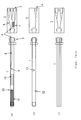
- FIG. 1 there is shown an organic synthesis reactor according to one embodiment of the present invention.
- Figs. 1a-c show top, bottom and side views, respectively.
- the reactor has a reagent introduction-and-reaction portion 2 that is connected at a contact portion 4 with an extensional reaction portion 1 via a connector jig 3.
- the extensional reaction portion 1 is made of a glass substrate having a thickness of 1 to 5 mm. Microchannels are formed on both surfaces of the glass substrate by wet etching or drilling.
- the glass substrate is provided with a through-hole 12 to permit a reagent solution to flow from the channel in the front surface to the channel in the rear surface.
- the width and depth of the channels are 50 to 500 ⁇ m.
- the design of the channels and machining method can be modified according to the purpose of use.
- the glass substrate having the microchannels are then held between two glass plates. These glass substrate and glass plates are bonded together by thermocompression.
- the whole assembly is finished in a cylindrical or prismatic form by a cutting technique.
- a glass stock may be machined into a semicylindrical form, and microchannels may be formed in this semicylindrical form.
- the length of the extensional reaction portion 1 is 50 to 300 mm.
- the diameter of the cylindrical form or the maximum width of the prismatic form is 2 to 10 mm.
- Screw holes are formed in the reagent introduction-and-reaction portion 2 to permit connection of tubes. Also, channels are formed in this portion 2. When the extensional reaction portion 1 and the reagent introduction-and-reaction portion 2 have been connected, their channels are aligned. Consequently, a reagent solution can be passed through the channels.
- the connector jig 3 has guide portions to facilitate aligning the extensional reaction portion 1 and reagent introduction-and-reaction portion 2.
- the contact portion 4 is surface-treated or used in combination with a sealant to prevent liquid leakage.
- Three reagent inlet holes 5 are formed in the reagent introduction-and-reaction portion 2. Two of the 3 inlet holes 5 meet each other and are combined into one conduit immediately ahead of a first reaction portion 7 formed within the reagent introduction-and-reaction portion 2. The conduit passes through the first reaction portion 7 of the bent channel, where a first reaction between reagents is produced. The conduit is in communication with a first reaction liquid channel 8 formed in the extensional reaction portion 1.
- a reagent inlet channel 6 extends from the remaining one of the reagent inlet holes 5 and meets the first reaction liquid channel 8 in a second reaction-and-mixture portion 9 formed in the extensional reaction portion 1, thus forming one conduit.
- This conduit is in communication with a second reaction portion 10 of the bent channel, where a second reaction between the reagents is induced.
- the second reaction portion 10 is in communication with a detection channel 11 of the bent channel.
- the second reaction portion 10 passes through a through-hole 12 and reaches the rear side of the extensional reaction portion 1, the through-hole 12 being formed in the vertical direction.
- the second reaction portion 10 then passes into the reaction liquid discharge hole 14 through a reaction liquid discharge channel 13.
- the 3 reagent inlet holes 5 and reaction liquid discharge hole 14 are formed in the same side surface of the reagent introduction-and-reaction portion 2.
- the microchannels in the microchip are formed in both top surface side and bottom surface side of the reagent introduction-and-reaction portion 2 and extensional reaction portion 1. That is, the present embodiment is characterized in that there are two layers of channels.
- the material of the organic synthesis reactor is so selected that the reactor can be used in a temperature range from -70°C to +200°C.
- the reagent introduction-and-reaction portion 2 is preferably made of a chemical resistant resin such as PEEK (polyetheretherketone), Teflon TM , or Diflon.
- the extensional reaction portion 1 is made of glass or quartz.
- the channels inside the reagent introduction-and-reaction portion 2 tend to be clogged up especially easily. Consequently, it can be anticipated that the running cost of the reactor in operation will be reduced by designing this portion tending to be clogged up as a replaceable external part attached to the extensional reaction portion 1.
- Fig. 2 shows an organic synthesis reactor according to another embodiment of the present invention.
- Figs. 2a-c show top, bottom and side views, respectively.
- the reactor has a reagent inlet portion 22 that is connected at a contact portion 24 with a reagent reaction portion 21 via a connector jig 23.
- the reagent reaction portion 21 is made of a glass substrate having a thickness of 1 to 5 mm. Microchannels are formed on both surfaces of the glass substrate by wet etching or drilling.
- the glass substrate is provided with a through-hole 33 to permit a reagent solution to flow from the channel in the front surface to the channel in the rear surface.
- the width and depth of the channels are 50 to 500 ⁇ m.
- the design of the channels and machining method can be modified according to the purpose of use.
- the glass substrate having the microchannels are then held between two glass plates. These glass substrate and glass plates are bonded together by thermocompression.
- the whole assembly is finished in a cylindrical or prismatic form by a cutting technique.
- a glass stock may be machined into a semicylindrical form, and microchannels may be formed in this semicylindrical form.
- the length of the reagent reaction portion 21 is 50 to 300 mm.
- the diameter of the cylindrical form or the maximum width of the prismatic form is 2 to 10 mm.
- Screw holes are formed in the reagent inlet portion 22 to permit connection of tubes. Also, channels are formed in the inlet portion 22. When the reagent reaction portion 21 and the reagent inlet portion 22 have been connected, their channels are aligned. Consequently, a reagent solution can be passed through the channels.
- the connector jig 23 has guide portions to facilitate aligning the reagent reaction portion 21 and reagent inlet portion 22.
- the contact portion 24 is surface-treated or used in combination with a sealant to prevent liquid leakage.
- Three reagent inlet holes 25 are formed in the reagent inlet portion 22 and are in communication with three reaction liquid channels 27, respectively, formed in the reagent reaction portion 21.
- Two of the 3 inlet holes 25 meet each other and are combined into one conduit in the first reaction-and-mixture portion 28.
- the conduit is in communication with the first reaction portion 29 of the bent channel, where a first reaction between reagents is produced.
- the conduit then meets another reaction liquid channel 27 in the second reaction-and-mixture portion 30 to form one conduit which is in communication with the second reaction portion 31 of the bent channel, where a second reaction between the reagents is induced.
- the second reaction portion 31 is in communication with a detection channel 32 of the bent channel.
- the detection channel 32 passes through a through-hole 33 and reaches the rear side of the reagent reaction portion 21, the through-hole 33 being formed in the vertical direction.
- the second reaction liquid then passes into the reaction liquid discharge hole 35 through a reaction liquid discharge channel 34.
- the 3 reagent inlet holes 25 and reaction liquid discharge hole 35 are formed in the same side surface of the reagent inlet portion 22.
- the microchannels in the microchip are formed in both top surface side and bottom surface side of the reagent inlet portion 22 and reagent reaction portion 21. That is, the present embodiment is characterized in that there are two layers of channels.
- the material of the organic synthesis reactor is so selected that the reactor can be used in a temperature range from -70°C to +200°C.
- the reagent inlet portion 22 is preferably made of a chemical resistant resin such as PEEK (polyetheretherketone), Teflon TM , or Diflon.
- the reagent reaction portion 21 is made of glass or quartz.
- the channels inside the reagent inlet portion 22 tend to be clogged up especially easily. Consequently, it can be anticipated that the running cost of the reactor in operation will be reduced by designing this portion tending to be clogged up as a replaceable external part attached to the reagent reaction portion 21.
- Fig. 3 shows an organic synthesis reactor according to a further embodiment of the present invention.
- Figs. 3a and 3b show a top and a bottom view, respectively.
- the reactor has a reagent inlet portion 52 that is connected at a contact portion 54 with a reagent reaction portion 51 via a connector jig 53 and using screws 55.
- the reagent reaction portion 51 is made of a glass substrate having a thickness of 1 to 5 mm. Microchannels are formed on both surfaces of the glass substrate by wet etching or drilling.
- the glass substrate is provided with a through-hole 64 to permit a reagent solution to flow from the channel in the front surface to the channel in the rear surface.
- the width and depth of the channels are 50 to 500 ⁇ m.
- the design of the channels and machining method can be modified according to the purpose of use.
- the glass substrate having the microchannels are then held between two glass plates. These glass substrate and glass plates are bonded together by thermocompression.
- One end portion of the assembly is cut into an elongated T-shaped form.
- the end portion of the reagent reaction portion 51 is shaped like the letter T to press and join the reagent inlet portion 52 by the connector jig 53.
- the T-shaped end portion of the reagent reaction portion 51 is made asymmetrical right and left to prevent the senses of the reagent reaction portion 51 and reagent inlet portion 52 from being confused when they are connected.
- the connector jig 53 has a structure for recognizing the asymmetrical portion or an asymmetrical fitting portion.
- Screw holes are formed in the reagent inlet portion 52 to permit connection of tubes. Also, channels are formed in the inlet portion 52. When the reagent reaction portion 51 and the reagent inlet portion 52 have been connected, their channels are aligned. Consequently, a reagent solution can be passed through the channels.
- the contact portion 54 is surface-treated or used in combination with a sealant to prevent liquid leakage.
- Three reagent inlet holes 56 are formed in the reagent inlet portion 52 and are in communication via three reagent inlet channels 57, respectively, with three reaction liquid channels 58, respectively, formed in the reagent reaction portion 51.
- Two of the 3 inlet holes 56 meet each other and are combined into one conduit in the first reaction-and-mixture portion 59.
- the conduit is in communication with the first reaction portion 60 of the bent channel, where a first reaction between reagents is produced.
- the conduit then meets another reaction liquid channel in the second reaction-and-mixture portion 61 to form one conduit which is in communication with the second reaction portion 62 of the bent channel, where a second reaction between the reagents is induced.
- the second reaction portion 62 is in communication with a detection channel 63 of the bent channel.
- the second reaction liquid passes through a through-hole 64 and reaches the rear side of the reagent reaction portion 62, the through-hole 64 being formed in the vertical direction.
- the second reaction liquid then passes into the reaction liquid discharge hole 66 through a reaction liquid discharge channel 65.
- the 3 reagent inlet holes 56 and reaction liquid discharge hole 66 are formed in the same side surface of the reagent inlet portion 52.
- the microchannels in the microchip are formed in both top surface side and bottom surface side of the reagent inlet portion 52 and reagent reaction portion 51. That is, the present embodiment is characterized in that there are two layers of channels.
- the material of the organic synthesis reactor is so selected that the reactor can be used in a temperature range from -70°C to +200°C.
- the reagent inlet portion 52 is preferably made of a chemical resistant resin such as PEEK (polyetheretherketone), Teflon TM , or Diflon.
- the reagent reaction portion 51 is made of glass or quartz.
- the channels inside the reagent inlet portion 52 tend to be clogged up especially easily. Consequently, it can be anticipated that the running cost of the reactor in operation will be reduced by designing this portion tending to be clogged up as a replaceable external part attached to the reagent reaction portion 51.
- Fig. 4 shows one embodiment of the present invention in which such an organic synthesis reactor is mounted in various analytical instruments.
- Liquid delivery modules 36, 37, and 38 such as syringe pumps are connected with the organic synthesis reactor by tubes such as capillaries.
- Reagent solutions sent out from the liquid delivery modules 36 and 37 are mixed by a mixing portion 28 where channels intersect.
- the solutions are reacted in a first reaction portion 29.
- the reagent solutions reacted in the first reaction portion are mixed with a reagent introduced from the liquid delivery module 38 in a mixing portion 30 located immediately behind the first reaction portion 29.
- a second stage of reaction is induced in a second reaction portion 31.
- a reaction inhibitor or diluting solvent may be introduced from the liquid delivery module 38.
- the reaction liquid obtained in the second reaction portion 31 is introduced into a detection channel 32, where the reaction products are detected by a thermal lens microscope 39.
- the reaction liquid is discharged out of the organic synthesis reactor from a reaction liquid discharge hole 35 through a through-hole 33 and through a reaction liquid discharge channel 34 in the rear surface. The liquid is then recovered.
- Fig. 5 shows an embodiment of the present invention in which the organic synthesis reactor is mounted in an NMR spectrometer.
- the organic synthesis reactor can be directly attached to the NMR spectrometer 40 of normal construction.
- the reactor and liquid delivery modules are connected by tubes such as capillaries.
- the reactor is mounted to an NMR sample tube holder having a diameter of 5 mm and to a rotor and inserted into an NMR probe having a diameter of 5 mm (finding the widest use). Under this condition, the reactor is used instead of an NMR sample tube.
- the organic synthesis reactor may also be combined with an electron spin resonance (ESR) spectrometer by a similar method.
- ESR electron spin resonance
- Fig. 6 shows an embodiment of the present invention in which the organic synthesis reactor is mounted in a mass spectrometer.
- MS detection can be easily performed simply by connecting a nano-electrospray nozzle 41 to a reaction liquid discharge hole 35.
- the operation regarding introduction of reagents is the same as in the third and fourth embodiments.
- the reaction liquid is discharged from the nano-electrospray nozzle. Mass spectra of the reaction products within the reaction liquid can be measured by electrospray ionization caused by application of a high voltage.
- the present invention can find wide application in research into organic synthesis and reactions.
Landscapes
- Chemical & Material Sciences (AREA)
- Chemical Kinetics & Catalysis (AREA)
- Physics & Mathematics (AREA)
- Dispersion Chemistry (AREA)
- Condensed Matter Physics & Semiconductors (AREA)
- General Physics & Mathematics (AREA)
- Organic Chemistry (AREA)
- Physical Or Chemical Processes And Apparatus (AREA)
- Organic Low-Molecular-Weight Compounds And Preparation Thereof (AREA)
- Investigating Or Analyzing Materials Using Thermal Means (AREA)
- Other Investigation Or Analysis Of Materials By Electrical Means (AREA)
- Automatic Analysis And Handling Materials Therefor (AREA)
Applications Claiming Priority (2)
| Application Number | Priority Date | Filing Date | Title |
|---|---|---|---|
| JP2005339570 | 2005-11-25 | ||
| JP2006110573A JP4753367B2 (ja) | 2005-11-25 | 2006-04-13 | 有機合成反応装置 |
Publications (1)
| Publication Number | Publication Date |
|---|---|
| EP1790411A1 true EP1790411A1 (fr) | 2007-05-30 |
Family
ID=37866202
Family Applications (1)
| Application Number | Title | Priority Date | Filing Date |
|---|---|---|---|
| EP06256020A Withdrawn EP1790411A1 (fr) | 2005-11-25 | 2006-11-24 | Appareil pour les synthèses et réactions organiques |
Country Status (3)
| Country | Link |
|---|---|
| US (1) | US20070148054A1 (fr) |
| EP (1) | EP1790411A1 (fr) |
| JP (1) | JP4753367B2 (fr) |
Cited By (1)
| Publication number | Priority date | Publication date | Assignee | Title |
|---|---|---|---|---|
| EP2407796A1 (fr) * | 2010-07-12 | 2012-01-18 | Bruker BioSpin Corporation | Cellule d'écoulement pour RMN |
Families Citing this family (4)
| Publication number | Priority date | Publication date | Assignee | Title |
|---|---|---|---|---|
| JP4933352B2 (ja) * | 2006-07-24 | 2012-05-16 | 株式会社 Jeol Resonance | Nmr装置 |
| WO2010102199A1 (fr) | 2009-03-06 | 2010-09-10 | Waters Technologies Corporation | Interface électromécanique et fluidique d'un substrat microfluidique |
| CA3033346A1 (fr) * | 2016-08-09 | 2018-02-15 | Beth Israel Deaconess Medical Center, Inc. | Systeme et procede pour dispositif d'hyperpolarisation a polarisation induite par parahydrogene microfluidique pour des applications d'imagerie par resonance magnetique (irm) et d e resonance magnetique nucleaire (rmn) |
| WO2021025105A1 (fr) * | 2019-08-06 | 2021-02-11 | 国立大学法人北海道大学 | Appareil de transfert de polarisation et dispositif microfluidique |
Citations (8)
| Publication number | Priority date | Publication date | Assignee | Title |
|---|---|---|---|---|
| WO1993022058A1 (fr) * | 1992-05-01 | 1993-11-11 | Trustees Of The University Of Pennsylvania | Analyse par amplification de polynucleotide a l'aide d'un dispositif micro-fabrique |
| WO1995026796A1 (fr) * | 1994-04-01 | 1995-10-12 | Integrated Chemical Synthesizers, Inc. | Synthetiseurs chimiques integres |
| US5519635A (en) * | 1993-09-20 | 1996-05-21 | Hitachi Ltd. | Apparatus for chemical analysis with detachable analytical units |
| DE19854096A1 (de) * | 1998-11-24 | 2000-05-25 | Merck Patent Gmbh | Anschlußträger für plattenförmige Mikrokomponenten |
| DE19945832A1 (de) * | 1999-09-24 | 2001-04-05 | Karlsruhe Forschzent | Modular aufgebauter Mikroreaktor |
| WO2002009867A1 (fr) * | 2000-07-27 | 2002-02-07 | Hte Aktiengesellschaft The High Throughput Experimentation Company | Agencement d'essai parallele de materiaux |
| WO2003106386A2 (fr) * | 2002-06-13 | 2003-12-24 | Velocys, Inc. | Deshydrogenation oxydante catalytique et reacteurs a microcanaux pour deshydrogenation oxydante catalytique |
| WO2006083437A2 (fr) * | 2004-12-30 | 2006-08-10 | Symyx Technologies, Inc. | Reacteur cinetique ideal de petite dimension pour evaluer des catalyseurs industriels de dimension ordinaire |
Family Cites Families (12)
| Publication number | Priority date | Publication date | Assignee | Title |
|---|---|---|---|---|
| JPS6120523Y2 (fr) * | 1980-10-24 | 1986-06-20 | ||
| US5498392A (en) * | 1992-05-01 | 1996-03-12 | Trustees Of The University Of Pennsylvania | Mesoscale polynucleotide amplification device and method |
| JP2001194373A (ja) * | 2000-01-06 | 2001-07-19 | Olympus Optical Co Ltd | 超小型化学操作装置 |
| US6827095B2 (en) * | 2000-10-12 | 2004-12-07 | Nanostream, Inc. | Modular microfluidic systems |
| US6653625B2 (en) * | 2001-03-19 | 2003-11-25 | Gyros Ab | Microfluidic system (MS) |
| ATE479899T1 (de) * | 2002-05-09 | 2010-09-15 | Univ Chicago | Einrichtugn und verfahren für druckgesteuerten plug-transport und reaktion |
| US20050169815A1 (en) * | 2002-05-13 | 2005-08-04 | Avantium International B.V. | System for chemical experiments |
| US20030224531A1 (en) * | 2002-05-29 | 2003-12-04 | Brennen Reid A. | Microplate with an integrated microfluidic system for parallel processing minute volumes of fluids |
| JP2004138583A (ja) * | 2002-10-21 | 2004-05-13 | Sumitomo Bakelite Co Ltd | 細胞機能測定用マイクロチップ |
| US7488454B2 (en) * | 2003-03-19 | 2009-02-10 | Tosoh Corporation | Microchannel structure body |
| FR2865806B1 (fr) * | 2004-01-30 | 2007-02-02 | Commissariat Energie Atomique | Laboratoire sur puce comprenant un reseau micro-fluidique et un nez d'electronebulisation coplanaires |
| JP4933352B2 (ja) * | 2006-07-24 | 2012-05-16 | 株式会社 Jeol Resonance | Nmr装置 |
-
2006
- 2006-04-13 JP JP2006110573A patent/JP4753367B2/ja active Active
- 2006-11-22 US US11/603,948 patent/US20070148054A1/en not_active Abandoned
- 2006-11-24 EP EP06256020A patent/EP1790411A1/fr not_active Withdrawn
Patent Citations (8)
| Publication number | Priority date | Publication date | Assignee | Title |
|---|---|---|---|---|
| WO1993022058A1 (fr) * | 1992-05-01 | 1993-11-11 | Trustees Of The University Of Pennsylvania | Analyse par amplification de polynucleotide a l'aide d'un dispositif micro-fabrique |
| US5519635A (en) * | 1993-09-20 | 1996-05-21 | Hitachi Ltd. | Apparatus for chemical analysis with detachable analytical units |
| WO1995026796A1 (fr) * | 1994-04-01 | 1995-10-12 | Integrated Chemical Synthesizers, Inc. | Synthetiseurs chimiques integres |
| DE19854096A1 (de) * | 1998-11-24 | 2000-05-25 | Merck Patent Gmbh | Anschlußträger für plattenförmige Mikrokomponenten |
| DE19945832A1 (de) * | 1999-09-24 | 2001-04-05 | Karlsruhe Forschzent | Modular aufgebauter Mikroreaktor |
| WO2002009867A1 (fr) * | 2000-07-27 | 2002-02-07 | Hte Aktiengesellschaft The High Throughput Experimentation Company | Agencement d'essai parallele de materiaux |
| WO2003106386A2 (fr) * | 2002-06-13 | 2003-12-24 | Velocys, Inc. | Deshydrogenation oxydante catalytique et reacteurs a microcanaux pour deshydrogenation oxydante catalytique |
| WO2006083437A2 (fr) * | 2004-12-30 | 2006-08-10 | Symyx Technologies, Inc. | Reacteur cinetique ideal de petite dimension pour evaluer des catalyseurs industriels de dimension ordinaire |
Non-Patent Citations (1)
| Title |
|---|
| KAMEOKA J ET AL: "An electrospray ionization source for integration with microfluidics", ANALYTICAL CHEMISTRY, AMERICAN CHEMICAL SOCIETY. COLUMBUS, US, vol. 22, no. 74, 15 November 2002 (2002-11-15), pages 5897 - 5901, XP001141044, ISSN: 0003-2700 * |
Cited By (1)
| Publication number | Priority date | Publication date | Assignee | Title |
|---|---|---|---|---|
| EP2407796A1 (fr) * | 2010-07-12 | 2012-01-18 | Bruker BioSpin Corporation | Cellule d'écoulement pour RMN |
Also Published As
| Publication number | Publication date |
|---|---|
| US20070148054A1 (en) | 2007-06-28 |
| JP2007171155A (ja) | 2007-07-05 |
| JP4753367B2 (ja) | 2011-08-24 |
Similar Documents
| Publication | Publication Date | Title |
|---|---|---|
| US8585986B1 (en) | Capillary interconnect device | |
| US6832787B1 (en) | Edge compression manifold apparatus | |
| US6481648B1 (en) | Spray tip for a microfluidic laboratory microchip | |
| US8163254B1 (en) | Micromanifold assembly | |
| US6867857B2 (en) | Flow cell for optical analysis of a fluid | |
| US8492165B2 (en) | Microfluidic interface | |
| CN102553665B (zh) | 一种微流控浓度梯度液滴生成芯片及生成装置及其应用 | |
| EP1790411A1 (fr) | Appareil pour les synthèses et réactions organiques | |
| CA2320296A1 (fr) | Cartouche d'analyse liquide | |
| EP1884792B1 (fr) | Spectromètre RMN et procédé de mesure par RMN | |
| WO2013061199A1 (fr) | Dispositif microfluidique à interconnexions | |
| Saarela et al. | Re-usable multi-inlet PDMS fluidic connector | |
| EP1872850B1 (fr) | Micropuce ayant une partie coulissante et une partie détecteur | |
| Zhang et al. | Paper spray mass spectrometry-based method for analysis of droplets in a gravity-driven microfluidic chip | |
| US8414785B2 (en) | Methods for fabrication of microfluidic systems on printed circuit boards | |
| CN111957361A (zh) | 微滴制备系统、微流控芯片及其设计方法 | |
| CN100498272C (zh) | 自动液体更换的微流控芯片毛细管电泳分析装置及使用方法 | |
| US9387475B2 (en) | Assembly of at least one microfluidic device and mounting piece | |
| EP4039359A1 (fr) | Puce à microcanaux | |
| KR101106612B1 (ko) | 유체특성 측정방법 및 그 측정장치 | |
| US6966336B1 (en) | Fluid injection microvalve | |
| CN212396772U (zh) | 微滴制备系统及微流控芯片 | |
| Renzi | Edge compression manifold apparatus | |
| Renzi | Fluid injection microvalve | |
| Salman et al. | Utilize smartphone as a novel detector for enzymatic urea hydrolysis in microfluidic system |
Legal Events
| Date | Code | Title | Description |
|---|---|---|---|
| PUAI | Public reference made under article 153(3) epc to a published international application that has entered the european phase |
Free format text: ORIGINAL CODE: 0009012 |
|
| AK | Designated contracting states |
Kind code of ref document: A1 Designated state(s): AT BE BG CH CY CZ DE DK EE ES FI FR GB GR HU IE IS IT LI LT LU LV MC NL PL PT RO SE SI SK TR |
|
| AX | Request for extension of the european patent |
Extension state: AL BA HR MK RS |
|
| 17P | Request for examination filed |
Effective date: 20070718 |
|
| 17Q | First examination report despatched |
Effective date: 20070817 |
|
| AKX | Designation fees paid |
Designated state(s): DE GB |
|
| RAP1 | Party data changed (applicant data changed or rights of an application transferred) |
Owner name: JEOL RESONANCE INC. Owner name: KANAGAWA ACADEMY OF SCIENCE AND TECHNOLOGY |
|
| STAA | Information on the status of an ep patent application or granted ep patent |
Free format text: STATUS: THE APPLICATION IS DEEMED TO BE WITHDRAWN |
|
| 18D | Application deemed to be withdrawn |
Effective date: 20150602 |