EP1790207A1 - Distributing device for product flow - Google Patents
Distributing device for product flow Download PDFInfo
- Publication number
- EP1790207A1 EP1790207A1 EP06120088A EP06120088A EP1790207A1 EP 1790207 A1 EP1790207 A1 EP 1790207A1 EP 06120088 A EP06120088 A EP 06120088A EP 06120088 A EP06120088 A EP 06120088A EP 1790207 A1 EP1790207 A1 EP 1790207A1
- Authority
- EP
- European Patent Office
- Prior art keywords
- distributor according
- edge
- stock
- control unit
- distributor
- Prior art date
- Legal status (The legal status is an assumption and is not a legal conclusion. Google has not performed a legal analysis and makes no representation as to the accuracy of the status listed.)
- Granted
Links
- 238000009826 distribution Methods 0.000 claims abstract description 47
- 238000003708 edge detection Methods 0.000 claims abstract description 13
- 238000011156 evaluation Methods 0.000 claims description 25
- 230000011514 reflex Effects 0.000 claims description 7
- 238000003306 harvesting Methods 0.000 claims description 6
- 238000003892 spreading Methods 0.000 claims description 6
- 230000007480 spreading Effects 0.000 claims description 6
- 230000001276 controlling effect Effects 0.000 claims description 5
- 230000001105 regulatory effect Effects 0.000 claims description 2
- 238000005520 cutting process Methods 0.000 description 33
- 239000010902 straw Substances 0.000 description 20
- 239000000463 material Substances 0.000 description 13
- 238000004140 cleaning Methods 0.000 description 8
- 230000007246 mechanism Effects 0.000 description 5
- 230000001419 dependent effect Effects 0.000 description 4
- 238000002360 preparation method Methods 0.000 description 4
- 230000008878 coupling Effects 0.000 description 3
- 238000010168 coupling process Methods 0.000 description 3
- 238000005859 coupling reaction Methods 0.000 description 3
- 210000005069 ears Anatomy 0.000 description 3
- 239000000470 constituent Substances 0.000 description 2
- 230000000694 effects Effects 0.000 description 2
- 238000000034 method Methods 0.000 description 2
- 239000000203 mixture Substances 0.000 description 2
- 230000008569 process Effects 0.000 description 2
- 238000002604 ultrasonography Methods 0.000 description 2
- 235000013399 edible fruits Nutrition 0.000 description 1
- 238000005259 measurement Methods 0.000 description 1
- 239000002245 particle Substances 0.000 description 1
- 239000000523 sample Substances 0.000 description 1
- 238000000926 separation method Methods 0.000 description 1
- 238000003860 storage Methods 0.000 description 1
- 230000032258 transport Effects 0.000 description 1
Images


Classifications
-
- A—HUMAN NECESSITIES
- A01—AGRICULTURE; FORESTRY; ANIMAL HUSBANDRY; HUNTING; TRAPPING; FISHING
- A01F—PROCESSING OF HARVESTED PRODUCE; HAY OR STRAW PRESSES; DEVICES FOR STORING AGRICULTURAL OR HORTICULTURAL PRODUCE
- A01F12/00—Parts or details of threshing apparatus
- A01F12/40—Arrangements of straw crushers or cutters
-
- A—HUMAN NECESSITIES
- A01—AGRICULTURE; FORESTRY; ANIMAL HUSBANDRY; HUNTING; TRAPPING; FISHING
- A01D—HARVESTING; MOWING
- A01D41/00—Combines, i.e. harvesters or mowers combined with threshing devices
- A01D41/12—Details of combines
- A01D41/1243—Devices for laying-out or distributing the straw
Definitions
- the invention relates to a distribution device for a product stream emerging from a harvester.
- the distribution device has baffles that are adjusted by a motor, so that the ejection direction is adjustable so that no material is thrown into the standing inventory.
- the motor is connected to a side recognition device which determines the position of the harvested part and / or not yet harvested part of the field to the harvester on the basis of the position and direction of the harvester in the field determined by a GPS-based position determining device and the field file stored in a storage unit and controls the motor depending on this calculated position.
- a disadvantage of this known distribution device is that it only works when the position-determining device receives the signal of the GPS system or signals are sent from the GPS system and the harvester in a given direction of travel must drive the field, otherwise the side of the stock as well the harvested field are reversed to the harvester.
- the invention is therefore based on the object to avoid the disadvantages of the prior art and in particular to vary the distribution width of the distributor and thereby to take into account the position of the stock edge.
- the distribution width of the distribution device can be adjusted so that the emerging from the distributor material flow is not thrown into the stock.
- the edge detection device is a locating device which detects a stock edge without contact, so that the edge detection device is designed wear.
- the locating device is advantageously connected to an evaluation unit, wherein the distance signals are transmitted to the evaluation unit.
- the evaluation unit determines with the removal signals whether the stock is arranged on the left side or right side of the stock edge and generates a left signal if the stock is left side of the stock edge and a right signal if the stock is located on the right side of the stock edge, so that the situation of the stock is automatically determined without the help of the driver, which means a relief for the driver.
- the evaluation unit is advantageously connected to a control unit, wherein the evaluation unit transmits the left signal and / or the right signal to the control unit so that the control unit constantly receives information about the position of the stock to the inventory edge
- An advantageous embodiment of the invention results from, if in the control unit, a first adjustment for regulating the distribution width and a second adjustment range for controlling the distribution width are stored and the control unit determines the first adjustment depending on the left signal and / or determines the second adjustment depending on the right signal, so that the adjustment is automatically selected without the driver's intervention.
- control unit generates control signals as a function of the specified adjustment range, with the control signals determining the stops or the swivel angle of the Gutleitelemefite so that an adjustment of the distribution width is carried out automatically.
- the harvester is a combine harvester and the distribution device is a chaff and / or Hiffselgutverteiler.
- the distribution device is a distribution hood with at least one pivotable baffle, wherein the control signal generated by the control unit limits the pivot angle of the baffle, so that the emerging from the distribution hood material flow is not thrown into the stock,
- the distributor has at least one throwing fan with a pivotable spoiler edge, wherein the control signal generated by the control unit limits the attacks of the spoiler edge, so that the emerging from the throwing blower stream is not thrown into the stock.
- the distributor is a radial fan with at least one oscillating discharge, wherein the control signal generated by the control unit limits the attacks of the discharge, so that the emerging from the radial fan flow is not thrown into the stock.
- the harvester has at least two locating devices, each generating distance signals, thus the combine harvester can track adjacent tracks on the field in opposite directions.
- the locating devices are connected to the evaluation unit and the locating devices transmit the distance signals to the control unit so that the evaluation unit determines from the distance signals which locating device detects a component edge.
- the evaluation unit is connected to an operating element via which an operator selects soft adjustment signals of the adjustment of the Gutleitelements is set so that the operator determines in the event that both locating devices detect a stock edge, which inventory edge relevant to the regulation of the distribution width is
- the locating device is formed by a reflex locating device, the scanning region of which can be directed ahead of time onto the crop edge, so that the ground edge is detected early.
- the reflex locator advantageously operates laser, ultrasound or infrared based so that the distances between the locator and the scanned area can be measured online.
- the edge detection direction is a button which is deflected in contact with the crop edge.
- the probe is a simple compared to the reflex locating device mechanical apparatus with sufficient accuracy.
- FIG. 1 shows the side view of a harvester 1 designed as a harvester with a known per se and therefore not described here threshing 2 and this downstream vibrating hanger 3 as a separating element 4.
- a cleaning device 5 consisting of two superimposed Seven 6, 7 and a cleaning fan 8.
- the invention is expressly not limited to such types of combine harvester.
- a cutting unit 10 is arranged on the combine harvester 1, with which the crop 9 is cut and picked up.
- the cutting unit 10 leads the crop 9 to a feeder 11, which is arranged on the front of the combine harvester 1.
- the inclined conveyor 4 transfers the crop 9 to the threshing mechanism 2 arranged in the machine housing 12.
- the threshing unit 2 processes the crop 9 intensively, so that the grains are released from the fruit of the crop 2.
- a predominant grain-chaff mixture 13 consisting of grains is deposited on the threshing and separating basket 14 of the threshing unit 2 and passes via a preparation tray 15 to the cleaning device 5 to remove the grains 16 from the non-grain constituents, that is to say stalks and spreaders 18 to separate.
- the threshing 2 In the rear region of the threshing 2 is associated with a rotating turning drum 19, which emerges from the threshing mechanism 2, essentially threshing straws existing crop 20 assumes and the shaker horde 3 feeds, which promotes the flow of material 20 in the rear region of the combine 1.
- the grains 16 still present in the flow 20 and possibly short straw 17 and chaff 18 are separated by passing through the sieve openings 3 provided with sieve openings 3 onto a return tray 22.
- the return tray 22 transports grains 16, short straw 17 and chaff 18 to the preparation tray 15th
- the grains 16, the short straw 17 and the chaff 18 likewise pass via the preparation floor 15 into the cleaning device 5, in which the grains 16 are separated from the short straw 17 and from the chaff 18.
- a screen passage 26 which passes through the top wire 6 in the tailback area 27 and a screen overflow 28 at the end of the bottom wire 7, usually contains heavier particles, ie unmanaged ears.
- the screen passage 26 together with the screen overflow 28 is referred to below as the so-called Kochpipeerntegutmenge 29.
- the Matter16 falls on an inclined collecting tray 30 below the cleaning device 5 and slides in a Ahren analogschnecke 31, The Ahren generalschnecke 31 promotes the Matterpipeerntegutmenge 29 in a ⁇ hrenelevator 32, which re-supplies the threshing unit 2.
- the grain elevator 35 conveys the grains 16 into the grain tank 36.
- the straw 40 and a certain percentage of lost grains 41 travel over the shaker hull 3 to the rear end of the combine harvester 1 and fall at the end of the Schüttlerhorde 3 in a straw chopper 42.
- the straw chopper 42 has a rotating cutter shaft 43 which is mounted in a chopper housing 44.
- the cutter shaft 44 is occupied with movable blades 45 which mesh with fixed knives 44 fixed counter knives 46. With these knives 45, 46, the straw 40 is crushed to shredded material and accelerated.
- the screen spill 38 which largely consists of chaff 37 and does not fall through the top wire 6, passes via the top wire 6 into the rear area of the combine harvester 1 and is likewise fed to the straw chopper 42.
- the material flow 47 emerging from the straw chopper 42 and containing the chaff and the chaff is fed radially to a downstream distribution device 48, which distributes the good flow 47 in the field.
- the distributor 48 does not promote the emerging from the combine harvester 1 good flow 47 in the standing stock on the field, the invention provides that a later to be described later Kantenerkennungsesrrtchtung 50 is provided, with the distance signals generated by this Kantenerkennungsehnchtung 50 the distribution width of Distributor 48 is adjustable.
- the combine harvester 1 can be assigned a plurality of distributing devices 48, wherein, for example, a distributing device 48 distributes the shredded material 47 leaving the straw chopper 42 and a further distributing device distributes the chaff 37 separately in the field, wherein the distribution widths of the distributing devices 48 can be controlled according to the invention with the distance signals generated by the edge detection device 50.
- the edge detection device 50 designed as a locating device 51 is arranged on the cutting unit 10, which scans the area in front of the cutting device 10 with a scanning beam 52 directed toward the crop 9 in the direction of travel FR of the combine harvester 1.
- any non-contact reflex locating device known to those skilled in the art such as a laser reflex locator, an infrared locator, or an ultrasound locator may be used.
- the distance between the locator 51 and the scanned area is known in the art Way determined by means of a transit time measurement between the transmitted and received radar, sound or light pulse.
- the locating device 51 is arranged on the left-hand cutting wall 53 of the cutting unit 10 as viewed in the direction of travel of the combine harvester 1, wherein the left-hand cutting board wall 53 limits the cutting width 54 of the cutting unit 10 on the left-hand side.
- the locating device 51 can optionally be converted to the right cutting wall 55 of the cutting unit 10, which limits the cutting width 54 of the cutting unit 10 on the right side.
- the scanning beam 52 is pivoted transversely to the direction of travel FR of the combine harvester 1 within a scanning region 56 and thereby scans a contour of the stock 57 located in front of the cutting unit 10 and the harvested field 58 located in front of the cutting unit 10.
- the locating device 51 generates, depending on the determined distances, distance signals ES, which are transmitted to an evaluation unit 59 connected to the respective locating device 51.
- the evaluation unit 59 determines with the distance signals ES whether the stock 57 is arranged on the left side or the right side of the stock edge 60 in the direction FR of the combine harvester 1, and generates a right signal RS when the stock 57 is arranged on the right side of the stock edge 60.
- the evaluation unit 59 is connected to a control unit 61, to which the evaluation unit 59 transmits the right signal RS.
- a first adjustment range 62 for the regulation of the distribution width 64 of the Hiffseigutverteilers 48 is stored.
- corresponding control commands Y, Z are transmitted to the distributing device 48 explained in more detail below, so that regulation of the distribution width 64 according to the invention depends on the distance signals ES generated by the locating device 51 and the distribution width 64 is reduced on the right side to increase the distance to the crop edge 65 newly created during harvesting.
- the locating device 51 can also be converted to the right-hand cutting wall 55 of the cutting unit 10, which limits the cutting width of the cutting unit 54 on the right-hand side.
- the evaluation unit 59 generates a link signal LS if it detects a stock edge 60 and the stock 57 is located on the left side of the stock edge 60.
- a second adjustment region 63 for controlling the distribution width 64 is stored in the control unit 61.
- a locating device 51 is attached to the cutting unit 10 both on the left-hand cutting-board wall 53 and on the right-hand cutting-board wall 55.
- the positioning preparations 51 generate distance signals ES, ES1 depending on the distances of the respective location device 51 to the inventory 57 or to the harvested field 58, respectively.
- Both locating devices 51 are connected to the evaluation unit 59, to which the removal signals ES, ES1 are transmitted.
- the evaluation unit 59 determines that the locating device 51 arranged on the left cutting wall 53 senses a stock edge 60 and the locating device 51 arranged on the cutting wall 55 does not detect a stock edge, the evaluating unit 59 generates a left signal LS and as soon as the evaluating unit 59 determines that the on the located on the left cutting wall 55 Ortungsvorrtchtung 51 sensed a stock edge and arranged on the left cutting wall 53 positioning device 51 no stock edge 60 sensed, the evaluation unit 59 generates a right signal RS.
- the evaluating unit generates both a right-hand signal R and a left-hand signal L, so that the distribution width 64 is reduced on both sides.
- the evaluation unit 59 is connected to a control element 66, wherein an operator can select via the operating element 66 whether the distance signals ES of the positioning device 51 arranged on the left cutting wall 53 or the distance signals ES1 of the positioning device arranged on the right-hand cutting wall 55 51 are to be used to control the distribution width 64 of the Hußselgutverteilers 48.
- a locating device 67 on the combine harvester so that its scanning beam 68 is directed to the stock 57 in the direction of travel FR to the right of the combine harvester.
- the spreading width 64 is reduced on the right side, if the locating device 67 does not recognize a crop edge, the spreading width 64 on the left side is reduced.
- the scanning beam 68 of the locating device 67 may also be directed to the stock in the direction of travel FR to the left of the combine harvester 1. Accordingly, the distribution width 64 is reduced on the left side if the locating device 67 recognizes a crop edge and reduces it on the right side if the locating device 67 does not recognize a crop edge.
- the distribution device 48 arranged in the rear region of the combine harvester 1 consists of two throwing blowers 70 which are mounted on a frame 71 on the chopper shaft 43 outside a chopper housing 44.
- a rearwardly projecting cover plate 72 (partially shown), in The axes of rotation 73 are occupied by flexible throwing vanes 74, which are bounded on the underside by a co-rotating disc 75, between the two of the upper cover plate 72, the rotating axes 73, the throwing blades 74 and the discs 75 formed blowers 70, a V-shaped Guttrennblech 76 is arranged, the tip 77 is directed against the coming of the straw chopper 42 crop flow 47 to divide this.
- the two legs 78 of Guttrennblechs 76 close a space between them and form rigid partial sheathing 79 for the throwers 70.
- These rigid partial sheaths 79 are followed by movable partial sheathing 80, which consist of a further wall portion 81.
- the wall portion 81 is fixed to an angle lever 82 which is rotatably mounted on a pin 83.
- the latter is firmly connected to a cross-beam 84, which is fastened to the frame 71 via lateral side members 85.
- an actuator 86 is articulated, which in turn is pivotally connected to the longitudinal member 85 and the movable part of the casing 80 drives.
- Both partial jackets 80 driven via the actuators 86 each form a tear-off edge 87 of an outlet opening of the throwing blower 70 running in the direction of rotation.
- the product stream 88 emerging from the throwing blower 70 is deflected by the break-off edges 87 on leaving the throwing blower 70 and distributed.
- the actuators 86 of the Generalummantelept 80 are connected to the control unit 61, which transmits the dependent of the corresponding adjustment range 62, 63 control signals Y, Z to the actuators 86 and thereby defines the stops for the Abrisskanten 87.
- the distribution width 64 of the crop stream 88 is set in the field such that will prevent the crop stream 88 is thrown into the stock 57.
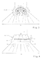
- FIG. 3 the rear portion of the plan view of a combine harvester 1 is shown with a radial fan 90 running as distribution device 48, which is the straw chopper (not shown) downstream.
- the radial fan 90 consists of two juxtaposed rotors 91 which rotate in opposite directions about parallel axes of rotation 92.
- Each rotor 91 is disposed in a housing 93 having a lower-side lid 94 and a circumference of the respective one Rotor 91 encompassing wall 95, wherein in the wall 95, an outlet opening 96 is provided, which is followed by a radial discharge channel 97.
- the housing 93 are each driven by an actuator 98 about the axis of rotation 92 of the associated rotor 91 oscillating, so that the position the discharge channels 97 changes continuously.
- the actuators 98 are connected to the control unit 61, which transmits the control signals Y, Z dependent on the corresponding adjustment range 62, 63 to the actuators 98 and thus defines the stops for the discharge channels 97, through which the distribution width 64 of the outlet from the radial blower 90 Good current 99 is specified on the field,
- FIG. 4 shows the rear region of a top view of a combine harvester 1 with a distribution device 48 designed as a distribution hood 103, which is arranged downstream of the straw chopper (not shown).
- a distribution device 48 designed as a distribution hood 103, which is arranged downstream of the straw chopper (not shown).
- a cover plate 104 a plurality of baffles 105 are arranged, which are mounted at its end facing the straw chopper pivotally mounted on the cover plate 104.
- the baffles 105 are connected to each other via a coupling mechanism 106 and are pivoted together via a hinged to the coupling mechanism 106 actuator 107.
- the actuator 107 is connected to the control unit 61, which transmits the control signal Y, Z dependent on the corresponding adjustment range 62, 63 to the actuator 107 and thus defines the pivot angle of the baffles 105 and thus the distribution width 64 of the output from the distribution hood 103 Gutstroms 108th determined on the field.
- the edge detection device 50 as a pushbutton, which is deflected when the contact edge 60, 65 is touched.
Abstract
Description
Die Erfindung betrifft eine Verteileinrichtung für einen aus einer Erntemaschine austretenden Gutstrom.The invention relates to a distribution device for a product stream emerging from a harvester.
Aus der
Nachteilig bei dieser bekannten Verteilvorrichtung ist, dass sie nur arbeitet, wenn die Positionsbestimmungseinrichtung die Signal des GPS-Systems empfängt beziehungsweise Signale vom GPS-System gesendet werden und das die Erntemaschine in einer vorgegebenen Fahrtrichtung das Feld befahren muss, da ansonsten die Seite des Bestand sowie des abgeernteten Feldes zur Erntemaschine vertauscht werden.A disadvantage of this known distribution device is that it only works when the position-determining device receives the signal of the GPS system or signals are sent from the GPS system and the harvester in a given direction of travel must drive the field, otherwise the side of the stock as well the harvested field are reversed to the harvester.
Der Erfindung liegt daher die Aufgabe zugrunde, die Nachteile des Standes der Technik zu vermeiden und insbesondere die Verteilbreite der Verteileinrichtung zu variieren und dabei die Lage der Bestandskante zu berücksichtigen.The invention is therefore based on the object to avoid the disadvantages of the prior art and in particular to vary the distribution width of the distributor and thereby to take into account the position of the stock edge.
Diese Aufgabe wird erfindungsgemäß durch die kennzeichnenden Merkmale des Anspruchs 1 gelöst Weitere vorteilhafte Wirkungen des Erfindungsgegenstandes ergeben sich aus den Unteransprüchen.This object is achieved by the characterizing features of
Indern die Regelung der Verteilbreite der Verteileinrichtung abhängig von den Entfernungssignalen der Karttenerkennungseinrichtung erfolgt, kann die Verteilbreite so verstellt werden, dass der aus der Verteileinrichtung austretende Gutstrom nicht in den Bestand geworfen wird.Indern the regulation of the distribution width of the distribution device is carried out depending on the distance signals of the Karttenerkennungseinrichtung, the distribution width can be adjusted so that the emerging from the distributor material flow is not thrown into the stock.
Vorteilhafterweise ist die Kantenerkennungseinrichtung eine Ortungsvorrichtung, die eine Bestandskante berührungslos detektiert, so dass die Kantenerkennungseinrichtung verschleißarm ausgeführt ist.Advantageously, the edge detection device is a locating device which detects a stock edge without contact, so that the edge detection device is designed wear.
Damit die Entfernungssignale rechnerunterstützt ausgewertet werden können, ist die Ortungsvorrichtung vorteilhafterweise mit einer Auswerteeinheit verbunden ist, wobei die Entfernungssignale an die Auswerteeinheit übermittelt werden.So that the distance signals can be evaluated with computer assistance, the locating device is advantageously connected to an evaluation unit, wherein the distance signals are transmitted to the evaluation unit.
In vorteilhafter Ausgestaltung der Erfindung ermittelt die Auswerteeinheit mit den Entfemungssignalen, ob der Bestand linksseitig oder rechtsseitig von der Bestandskante angeordnet ist und generiert ein Linkssignal, wenn der Bestand linksseitig der Bestandkante angeordnet ist und ein Rechtssignal wenn der Bestand rechtsseitig von der Bestandskante angeordnet ist, so dass die Lage des Bestandes automatisch ohne die Hilfe des Fahrers ermittelt wird, was eine Entlastung für den Fahrer bedeutet.In an advantageous embodiment of the invention, the evaluation unit determines with the removal signals whether the stock is arranged on the left side or right side of the stock edge and generates a left signal if the stock is left side of the stock edge and a right signal if the stock is located on the right side of the stock edge, so that the situation of the stock is automatically determined without the help of the driver, which means a relief for the driver.
Die Auswerteeinheit ist vorteilhafterweise mit einer Steuereinheit verbunden, wobei die Auswerteeinheit das Linkssignal und/oder das Rechtssignal an die Steuereinheit übermittelt so dass die Steuereinheit ständig Informationen über die Lage des Bestandes zur Bestandskante erhältThe evaluation unit is advantageously connected to a control unit, wherein the evaluation unit transmits the left signal and / or the right signal to the control unit so that the control unit constantly receives information about the position of the stock to the inventory edge
Eine vorteilhafte Ausgestaltung der Erfindung ergibt sich dadurch, wenn in der Steuereinheit ein erster Verstellbereich zur Regelung der Verteilbreite und ein zweiter Verstellbereich zur Regelung der Verteilbreite gespeichert sind und die Steuereinheit abhängig vom Linkssignal den ersten Verstellbereich festlegt und/oder abhängig vom Rechtssignal den zweiten Verstellbereich festlegt, so dass auch der Verstellbereich ohne Zutun des Fahrers automatisch ausgewählt wird.An advantageous embodiment of the invention results from, if in the control unit, a first adjustment for regulating the distribution width and a second adjustment range for controlling the distribution width are stored and the control unit determines the first adjustment depending on the left signal and / or determines the second adjustment depending on the right signal, so that the adjustment is automatically selected without the driver's intervention.
Vorteilhafterweise generiert die Steuereinheit in Abhängigkeit vom festgelegten Verstellbereich Steuersignale, wobei mit den Steuersignalen die Festlegung der Anschläge oder der Schwenkwinkel der Gutleitelemefite erfolgt so dass eine Anpassung der Verteilbreite selbsttätig erfolgt.Advantageously, the control unit generates control signals as a function of the specified adjustment range, with the control signals determining the stops or the swivel angle of the Gutleitelemefite so that an adjustment of the distribution width is carried out automatically.
In einer vorteilhaften Ausgestaltung der Erfindung ist die Erntemaschine ein Mähdrescher und die Verteileinrichtung ein Spreu- und/oder Häckselgutverteiler.In an advantageous embodiment of the invention, the harvester is a combine harvester and the distribution device is a chaff and / or Häckselgutverteiler.
In vorteilhafter Weiterbildung der Erfindung ist die Verteileinrichtung eine Verteilhaube mit zumindest einem verschwenkbaren Leitblech, wobei das von der Steuereinheit generierte Steuersignal den Verschwenkwinkel des Leitblechs begrenzt, so dass der aus der Verteilhaube austretende Gutstrom nicht in den Bestand geworfen wird,In an advantageous embodiment of the invention, the distribution device is a distribution hood with at least one pivotable baffle, wherein the control signal generated by the control unit limits the pivot angle of the baffle, so that the emerging from the distribution hood material flow is not thrown into the stock,
In vorteilhafter Weiterbildung der Erfindung weist die Verteileinrichtung wenigstens ein Wurfgebläse mit einer verschwenkbaren Abrisskante auf, wobei das von der Steuereinheit generierte Steuersignal die Anschläge der Abrisskante begrenzt, damit der aus dem Wurfgebläse austretende Gutstrom nicht in den Bestand geworfen wird.In an advantageous embodiment of the invention, the distributor has at least one throwing fan with a pivotable spoiler edge, wherein the control signal generated by the control unit limits the attacks of the spoiler edge, so that the emerging from the throwing blower stream is not thrown into the stock.
In vorteilhafter Weiterbildung der Erfindung ist die Verteileinrichtung ein Radialgebläse mit wenigstens einem oszillierenden Austragkanal, wobei das von der Steuereinheit generierte Steuersignal die Anschläge des Austragkanals begrenzt, so dass der aus dem Radialgebläse austretende Gutstrom nicht in den Bestand geworfen wird.In an advantageous embodiment of the invention, the distributor is a radial fan with at least one oscillating discharge, wherein the control signal generated by the control unit limits the attacks of the discharge, so that the emerging from the radial fan flow is not thrown into the stock.
Vorteilhafterweise weist die Erntemaschine wenigstens zwei Ortungsvorrichtungen aufweist, die jeweils Entfernungssignale generieren, damit der Mähdrescher nebeneinanderliegende Spuren auf dem Feld in entgegengesetzten Fahrtrichtungen abernten kann.Advantageously, the harvester has at least two locating devices, each generating distance signals, thus the combine harvester can track adjacent tracks on the field in opposite directions.
In vorteilhafter Weiterbildung der Erfindung sind die Ortungsvorrichtungen mit der Auswerteeinheit verbunden und die Ortungsvorrichtungen übermitteln die Entfernungssignale an die Steuereinheit so dass die Auswerteeinheit anhand der Entfernungssignale ermittelt, welche Ortungsvorrichtung eine Bestandkante erfasst.In an advantageous embodiment of the invention, the locating devices are connected to the evaluation unit and the locating devices transmit the distance signals to the control unit so that the evaluation unit determines from the distance signals which locating device detects a component edge.
Vorteilhafterweise ist die Auswerteeinheit mit einem Bedienelement verbunden, über das ein Bediener auswählt, mit weichen Entferntingssignale der Verstellbereich des Gutleitelements festgelegt wird, so dass der Bediener für den Fall, dass beide Ortungsvorrichtungen eine Bestandskante erfassen, festlegt, welche Bestandskante für die Regelung der Verteilbreite relevant istAdvantageously, the evaluation unit is connected to an operating element via which an operator selects soft adjustment signals of the adjustment of the Gutleitelements is set so that the operator determines in the event that both locating devices detect a stock edge, which inventory edge relevant to the regulation of the distribution width is
Vorteilhafterweise wird die Ortungsvorrichtung von einer Reflex-Ortungsvorrichtung gebildet, deren Abtastbereich vorausschauend auf die Bestandskante gerichtet werden kann, so dass die Bestandkante frühzeitig erkannt wird.Advantageously, the locating device is formed by a reflex locating device, the scanning region of which can be directed ahead of time onto the crop edge, so that the ground edge is detected early.
Die Reflex-Ortungsvorrichtung arbeitet vorteilhafterweise Laser-, Ultraschall- oder Infrarot-basiert, so dass die Entfernungen zwischen der Ortungsvorrichtung und dem abgetasteten Bereich online gemessen werden können.The reflex locator advantageously operates laser, ultrasound or infrared based so that the distances between the locator and the scanned area can be measured online.
In einer alternativen Ausführung der Erfindung ist die Kantenerkennungselnrichtung ein Taster, der bei Berührung mit der Bestandskante ausgelenkt wird. Der Taster ist eine im Vergleich zur Reflex-Ortungsvorrichtung einfache mechanische Apparatur mit ausreichender Genauigkeit.In an alternative embodiment of the invention, the edge detection direction is a button which is deflected in contact with the crop edge. The probe is a simple compared to the reflex locating device mechanical apparatus with sufficient accuracy.
Weitere vorteilhafte Ausgestaltungen sind Gegenstand weiterer Unteransprüche und werden nachfolgend an Hand der in mehrerer Figuren dargestellten Ausführungsbeispiele näher erläutert.Further advantageous embodiments are the subject of further subclaims and are explained in more detail below with reference to the exemplary embodiments illustrated in several figures.
Es zeigen:
- Fig. 1 eine schematische Seitenansicht eines Mähdreschers mit einer erfindungsgemäßen Verteileinrichtung
- Fig.1 zeigt eine schematische Draufsicht auf einen Mähdrescher gemäß der Fig. 1,
- Fig.3 zeigt eine Draufsicht auf eine als Radialgebläse ausgeführte, erfindungsgemäße Verteileinrichtung,
- Fig.4 zeigt eine Draufsicht auf eine als Verteil haube ausgeführte, erfindungsgemäßen Verteileinrichtung.
- Fig. 1 is a schematic side view of a combine with a distribution device according to the invention
- 1 shows a schematic plan view of a combine harvester according to FIG. 1,
- 3 shows a plan view of a radial fan designed as a distribution device according to the invention,
- 4 shows a plan view of a distribution hood designed as distribution device according to the invention.
Fig.1 zeigt die Seitenansicht einer als Mähdrescher 1 ausgeführten Erntemaschine mit einem an sich bekannten und daher hier nicht näher beschriebenen Dreschwerk 2 und einer diesem nachgeordneten Schüttlerhorde 3 als Abscheideorgan 4. Unterhalb der Schüttlerhorde 3 befindet sich eine Reinigungseinrichtung 5, bestehend aus zwei übereinander angeordneten Sieben 6, 7 und einem Reinigungsgebläse 8. Die Erfindung ist aber ausdrücklich nicht auf derartig ausgeführte Mähdreschertypen beschränkt. Im vorderen Bereich ist an dem Mähdrescher 1 ein Schneidwerk 10 angeordnet, mit dem das Erntegut 9 geschnitten und aufgenommen wird. Das Schneidwerk 10 führt das Erntegut 9 einem Schrägförderer 11 zu, der frontseitig am Mähdrescher 1 angeordnet ist. Der Schrägförderer 4 übergibt das Erntegut 9 an das im Maschinengehause 12 angeordnete Dreschwerk 2. Das Dreschwerk 2 bearbeitet das Erntegut 9 intensiv, so dass die Körner aus den Früchten des Ernteguts 2 herausgelöst werden. Ein überwiegenden aus Körnern bestehendes Korn-Spreu-Gemisch 13 wird an dem Dresch- und Abscheidekorb 14 des Dreschwerks 2 abgeschieden und gelangt über einen Vorbereitungsboden 15 zu der Reinigungseinrichtung 5, um die Körner 16 von den Nichtkornbestandteilen, das heißt von Halm- 17 und Spreuteilen 18 zu trennen. Im rückwärtigen Bereich ist dem Dreschwerk 2 eine rotierende Wendetrommel 19 zugeordnet, die den aus dem Dreschwerk 2 austretenden, im wesentlichen aus ausgedroschenen Halmen bestehenden Gutstrom 20 annimmt und der Schüttlerhorde 3 zuführt, die den Gutstrom 20 in den rückwärtigen Bereich des Mähdreschers 1 fördert.
Dabei werden die noch im Gutstrom 20 befindlichen Körner 16 sowie eventuell Kurzstroh 17 und Spreu 18 abgetrennt, indem sie durch die mit Sieböffnungen 21 versehene Schüttlerhorde 3 hindurch auf einen Rücklaufboden 22 fallen, Der Rücklaufboden 22 transportiert Körner 16, Kurzstroh 17 und Spreu 18 zum Vorbereitungsboden 15.
Die Körner 16, das Kurzstroh 17 und die Spreu 18 gelangen schließlich ebenfalls über den Vorbereitungsboden 15 in die Reinigungseinrichtung 5, in welcher die Körner 16 vom Kurzstroh 17 und von der Spreu 18 getrennt werden.
Dies erfolgt in der Weise, dass durch die Sieböffnungen 23, 24 im Obersieb 6 und im Untersieb 7 mittels des Gebläses 8 ein Luftstrom hindurchgefördert wird, welcher das über die Siebe 6, 7 in den hinteren Bereich des Mähdreschers 1 geführte Erntegut 25 auflockert und für das Heraustrennen der spezifisch leichteren Spreu- und Kurzstrohanteile 17, 18 sorgt, während die schweren Erntegutkörner 16 durch die Sieböffnungen 23, 24 fallen.
Ein Siebdurchgang 26, der im Überkehrbereich 27 durch das Obersieb 6 hindurchfällt und ein Siebüberlauf 28 am Ende des Untersiebs 7, enthält in der Regel schwerere Teilchen, d. h. unausgedroschene Ähren. Der Siebdurchgang 26 zusammen mit dem Siebüberlauf 28 wird nachfolgend als sogenannte Überkehrerntegutmenge 29 bezeichnet. Die Überkehrerntegutmenge 29 fällt auf einen schräg verlaufenden Auffangboden 30 unterhalb der Reinigungseinrichtung 5 und gleitet in eine Ahrenförderschnecke 31, Die Ahrenförderschnecke 31 fördert die überkehrerntegutmenge 29 in einen Ährenelevator 32, der sie erneut dem Dreschwerk 2 zuführt.
Die Körner 16, welche durch beide Siebe 6, 7 der Reinigungsvorrichtung 5 gelangt sind, fallen auf einen weiteren schräg verlaufenden Auffang- und Führungsboden 33 und gleiten in eine Kornförderschnecke 34, die die Körner 16 einem Kornelevator 35 zuführt. Der Kornelevator 35 fördert die Körner 16 in den Korntank 36.
Das Stroh 40 sowie ein bestimmter Prozentsatz an Verlustkörnern 41 wandern über die Schüttlerhorde 3 zum hinteren Ende des Mähdreschers 1 und fallen am Ende der Schüttlerhorde 3 in einen Strohhäcksler 42. Der Strohhäcksler 42 weist eine rotierende Häckslerwelle 43 auf, die in einem Häckslergehäuse 44 gelagert ist. Die Häckslerwelle 44 ist mit beweglichen Messern 45 besetzt, die mit im Häckslergehäuse 44 fest angeordneten Gegenmessern 46 kämmen. Mit diesen Messern 45, 46 wird das Stroh 40 zu Häckselgut zerkleinert und beschleunigt.
Der größtenteils aus Spreu 37 bestehende Siebüberlauf 38, der nicht durch das Obersieb 6 hindurch fällt, gelangt über das Obersieb 6 in den hinteren Bereich des Mähdreschers 1 und wird ebenfalls dem Strohhäcksler 42 zugeführt.
Der aus dem Strohhäcksler 42 austretende, die Spreu und das Häckselgut enthaltene Gutstrom 47 wird einer an späterer Stelle näher erläuterten, nachgeordneten Verteileinrichtung 48 radial zugeführt, die den Gutstrom 47 auf dem Feld verteilt. Damit die Verteileinrichtung 48 den aus dem Mähdrescher 1 austretende Gutstrom 47 nicht in den stehenden Bestand auf dem Feld fördert, ist erfindungsgemäß vorgesehen, dass eine später noch näher zu beschreibende Kantenerkennungsesnrtchtung 50 vorgesehen ist, wobei mit den von dieser Kantenerkennungsehnchtung 50 generierten Entfernungssignalen die Verteilbreite der Verteileinrichtung 48 regelbar ist.
Es liegt im Rahmen der Erfindung, dass dem Mähdrescher 1 mehrere Verteileinrichtungen 48 zugeordnet sein können, wobei beispielsweise eine Verteilvorrichtung 48 das aus dem Strohhäcksler 42 austretende Häckselgut 47 und eine weitere Verteileinrichtung die Spreu 37 separat auf dem Feld verteilt, wobei die Verteilbreiten der Verteileinrichtungen 48 erfindungsgemäß mit den von der Kantenerkennungseinrichtung 50 generierten Entfernungssignalen regelbar sind.
Oberhalb des Erntegutes 9 ist die als Ortungsvorrichtung 51 ausgeführte Kantenerkennungseinnchtung 50 an dem Schneidwerk 10 angeordnet, die mit einem in Fahrtrichtung FR des Mähdreschers 1 vorrausschauenden, zum Erntegut 9 gerichteten Abtaststrahl 52 den Bereich vor dem Schneidwerk 10 abtastet. Als Ortungsvorrichtung 51 kann jede dem Fachmann bekannte, berührungslos arbeitende Reflex-Ortungsvorrichtung, wie beispielsweise eine Laserreflexortungsvorrichtung, eine infrarotortungsvorrichtung oder eine Ultraschallortungsvorrichtung verwendet werden. Die Entfernung zwischen der Ortungsvorrichtung 51 und dem abgetastetem Bereich wird in an sich bekannter Weise mittels einer Laufzeitmessung zwischen dem gesendeten und empfangenen Radar, Schall- oder Lichtimpuls bestimmt.1 shows the side view of a
In the process, the
Finally, the
This is done in such a way that through the
A screen passage 26 which passes through the top wire 6 in the tailback area 27 and a
The
The straw 40 and a certain percentage of lost grains 41 travel over the shaker hull 3 to the rear end of the
The screen spill 38, which largely consists of chaff 37 and does not fall through the top wire 6, passes via the top wire 6 into the rear area of the
The
It is within the scope of the invention that the
Above the crop 9, the
Fig.2 zeigt die schematische Draufsicht des in Fig.1 dargestellten Mähdreschers 1. Die Ortungsvorrichtung 51 ist an der in Fahrtrichtung des Mähdreschers 1 gesehen linken Schneidwerkswand 53 des Schneidwerks 10 angeordnet, wobei die linke Schneidwerkswand 53 die Schnittbreite 54 des Schneidwerks 10 linksseitig begrenzt. Die Ortungsvorrichtung 51 kann wahlweise auch auf die rechte Schneidwerkswand 55 des Schneidwerks 10 umgebaut werden, welche die Schnittbreite 54 des Schneidwerks 10 rechtsseitig begrenzt.
Der Abtaststrahl 52 wird innerhalb eines Abtastbereichs 56 quer zur Fahrtrichtung FR des Mähdreschers 1 verschwenkt und tastet dabei eine Kontur des vor dem Schneidwerk 10 liegenden Bestandes 57 und des vor dem Schneidwerk 10 liegenden abgeernteten Feldes 58 ab. Die Ortungseinrichtung 51 generiert abhängig von den ermittelten Entfernungen Entfernungssignale ES, die an eine mit der jeweiligen Ortungsvorrichtung 51 verbundenen Auswerteeinheit 59 übermittelt werden. Die Auswerteeinheit 59 erkennt dabei beispielsweise anhand eines Entfernungssprungs oder Extremwerten der ausgewerteten Entfernungssignale ES eine Bestandskante 60. Gleichzeitig ermittelt die Auswerteeinheit 59 mit den Entfernungssignalen ES, ob der Bestand 57 in Fahrtrichtung FR des Mähdreschers 1 gesehen linksseitig oder rechtsseitig von der Bestandskante 60 angeordnet ist und generiert ein Rechtssignal RS, wenn der Bestand 57 rechtsseitig von der Bestandskante 60 angeordnet ist. Die Auswerteeinheit 59 ist mit einer Steuereinheit 61 verbunden, an die die Auswerteeinheit 59 das Rechtssignal RS übermittelt.
In der Steuereinheit 61 ist für das Rechtssignal RS ein erster Verstellbereich 62 für die Regelung der Verteilbreite 64 des Häckseigutverteilers 48 gespeichert. Abhängig vom Verstellbereich 62 werden entsprechende Steuerbefehle Y, Z an die an späterer Stelle noch näher erläuterte Verteileinrichtung 48 übermittelt, so dass die Regelung der Verteilbreite 64 erfindurigsgemäß abhängig von den von der Ortungsvorrichtung 51 generierten Entfernungssignalen ES erfolgt und die Verteilbreite 64 rechtsseitig verringert wird, um den Abstand zu der beim Ernten neu entstehenden Bestandskante 65 zu vergrößern. Erkennt die Ortungsvorrichtung 51 keine Erntegutkante 60, was beispielsweise bei der ersten Durchfahrt durch den Bestand vorkommt, so wird die Verteilbreite 64 beidseitig verringert, damit die Spreu weder in den links noch in den rechts vom Mähdrescher 1 stehenden Bestand geworfen wird.
Die Ortungsvorrichtung 51 kann wahlweise auch auf die rechte Schneidwerkwand 55 des Schneidwerks 10 umgebaut werden, welche die Schnittbreite des Schneidwerks 54 rechtsseitig begrenzt. In diesem Fall generiert die Auswerteeinheit 59 ein Linkssignal LS, wenn sie eine Bestandskante 60 erkennt und der Bestand 57 linksseitig der Bestandkante 60 angeordnet ist. Für die Linkssignale LS ist in der Steuereinheit 61 ein zweiter Verstellbereich 63 zur Steuerung der Verteilbreite 64 gespeichert. Die wechselweise Anbringung der Ortungsvorrichtung 51 entweder an der linken Schneidwerkswand 53 oder der linken Schneidwerkwand 55 erfordert, dass die landwirtschaftliche Arbeitsmaschine so durch den Bestand 57 fährt, dass die Bestandskante 60 stets im Abtastbereich 56 der Ortungsvorrichtung 51 liegt. Dies erfordert, dass der Mähdrescher stets in Abhängigkeit von der Lage der Ortungsvorrichtung 51 am Schneidwerk 10 in den Bestand fahren muss.
Um das Einfahren des Mähdreschers 1 von der Lage der Ortungsvorrichtung 51 zu entkoppeln, ist es denkbar, dass sowohl an der linken Schneidwerkswand 53 als auch an der rechten Schneidwerkswand 55 eine Ortungsvorrichtung 51 an dem Schneidwerk 10 angebracht ist. Die Ortungsvorfichtungen 51 generieren abhängig von der Entfernungen der jeweiligen Ortungsvorrichtung 51 zum Bestand 57 beziehungsweise zum abgeerntetem Feld 58 Entfernungssignale ES, ES1. Beide Ortungsvorrichtungen 51 sind mit der Auswerteeinheit 59 verbunden, an die die Entfernurigssignate ES, ES1 übermittelt werden. Sobald die Auswerteeinheit 59 ermittelt, dass die auf der linken Schneidwerkswand 53 angeordnete Ortungsvorrichtung 51 eine Bestandskante 60 und die auf der Schneidwerkswand 55 angeordnete Ortungsvorrichtung 51 keine Bestandskante sensiert, generiert die Auswerteeinheit 59 ein Linkssignal LS und sobald die Auswerteeinheit 59 ermittelt, dass die auf der rechten Schneidwerkswand 55 angeordnete Ortungsvorrtchtung 51 eine Bestandskante sensiert und die auf der linken Schneidwerkswand 53 angeordnete Ortungsvorrichtung 51 keine Bestandskante 60 sensiert, generiert die Auswerteeinheit 59 ein Rechtssignal RS. Dies erfolgt vor dem Hintergrund, dass wenn die linke Ortungsvorrichtung 51 beim Ernten eine Bestandkante 60 sensiert, der Bestand 57 üblicherweise rechtsseitig der Bestandskante 60 angeordnet ist und dass wenn die rechte Ortungsvorrichtung 51 beim Ernten eine Bestandkante sensiert, der Bestand 57 üblicherweise linksseitig der Bestandskante angeordnet ist.
Sensieren beide Ortungsvorrichtung 51 jeweils eine Bestandskante 60 oder sensieren beide Ortungsvorrichtung keine Bestandskanten, generiert die Auswerteeinheit sowohl ein Rechtssignal R und ein Linkssignal L, so dass die Verteilbreite 64 beidseitig reduziert wird,
Es ist denkbar, dass die Auswerteeinheit 59 mit einem Bedienelement 66 verbunden ist, wobei ein Bediener über das Bedienelement 66 auswählen kann, ob die Entfernungssignale ES der auf der linken Schneidwerkswand 53 angeordneten Ortungsvorrichtung 51 oder die Entfernungssignale ES1 der auf der rechten Schneidwerkswand 55 angeordneten Ortungsvorrichtung 51 zur Steuerung der Verteilbreite 64 des Häckselgutverteilers 48 herangezogen werden sollen.
Ebenso ist es denkbar, eine Ortungsvorrichtung 67 so am Mähdrescher anzuordnen, dass deren Abtaststrahl 68 auf den Bestand 57 in Fahrtrichtung FR rechts neben dem Mähdrescher gerichtet ist. Erkennt die Ortungsvorrichtung 67 eine Erntegutkante 65, so wird die Verteilbreite 64 rechtsseitig reduziert, erkennt die Ortungsvorrichtung 67 keine Erntegutkante, so wird die Verteilbreite 64 linksseitig reduziert. Die Abtaststrahl 68 der Ortungsvorrichtung 67 kann auch auf den Bestand in Fahrtrichtung FR links neben den Mähdrescher 1 gerichtet sein. Entsprechend wird die Verteilbreite 64 linksseitig reduziert, wenn die Ortungsvorrichtung 67 eine Erntegutkante erkennt und rechtsseitig reduziert, wenn die Ortungsvorrichtung 67 keine Erntegutkante erkennt.
Ebenso ist vorstellbar, die Entfernungssignale einer die Bestand kante 60 vor dem Schneidwerk 10 sensierenden Ortungsvorrichtung 51 und einer die bei der Erntefahrt entstehende Bestandskante 65 sensierenden Ortungsvorrichtung 67 zur Regelung der Verteilbreite 64 kombiniert zu nutzen.1 shows the schematic plan view of the
The
In the
Optionally, the locating device 51 can also be converted to the right-
In order to decouple the retraction of the
If both locating devices 51 respectively sense a
It is conceivable that the evaluation unit 59 is connected to a
Likewise, it is conceivable to arrange a locating
Likewise, it is conceivable to use the distance signals of a
Die im hinteren Bereich des Mähdreschers 1 angeordnete Verteileinrichtung 48 besteht aus zwei Wurfgebläsen 70, die auf einem Rahmen 71 der außerhalb eines Häckslergehäuses 44 auf der Häckslerwelle 43 gelagert ist. Mit dem Rahmen 71 ist ein nach hinten auskragendes Abdeckblech 72 (teilweise dargestellt) verbunden, in dem die Rotationsachsen 73 gelagert sind, Die Rotationsachsen 73 sind mit flexiblen Wurfschaufeln 74 besetzt, die unterseitig von einer mitrotierenden Scheibe 75 begrenzt werden, Zwischen den beiden aus dem oberen Abdeckblech 72, den rotierenden Achsen 73, den Wurfschaufeln 74 und den Scheiben 75 gebildeten Wurfgebläsen 70 ist ein V-förmiges Guttrennblech 76 angeordnet, dessen Spitze 77 gegen den von dem Strohhäcksler 42 kommenden Gutstrom 47 gerichtet ist, um diesen aufzuteilen. Die beiden Schenkel 78 des Guttrennblechs 76 schließen einen Raum zwischen sich ein und bilden starre Teilummantelungen 79 für die Wurfgebläse 70. An diese starren Teilummantelungen 79 schließen sich bewegliche Teilummantelungen 80 an, die aus einem weiteren Wandungsteil 81 bestehen. Das Wandungsteil 81 ist an einem Winkelhebel 82 befestigt, der auf einem Zapfen 83 drehbar aufgesetzt ist. Letzterer ist mit einer Quertraverse 84 fest verbunden, die über seitliche Längsträger 85 an dem Rahmen 71 befestigt ist. An dem anderen Ende des Winkelhebels 82 ist ein Stellglied 86 angelenkt, das seinerseits gelenkig mit dem Längsträger 85 verbunden ist und die bewegliche Teilummantelung 80 antreibt. Beide über die Stellglieder 86 angetriebenen Teilummantelungen 80 bilden jeweils eine in Rotationsrichtung laufende Abrisskante 87 einer Auslassöffnung des Wurfgebläses 70. Der aus dem Wurfgebläse 70 austretende Gutstrom 88 wird durch die Abrisskanten 87 beim Austreten aus dem Wurfgebläse 70 umgelenkt und verteilt. Die Stellglieder 86 der Teilummantelungen 80 sind mit der Steuereinheit 61 verbunden, die die von dem entsprechenden Verstellbereich 62, 63 abhängigen Steuersignale Y, Z an die Stellglieder 86 übermittelt und dadurch die Anschläge für die Abrisskanten 87 definiert. Durch die Verstellbereiche 62, 63 wird die Verteilbreite 64 des Gutstromes 88 auf dem Feld derart vorgegeben, dass verhindern wird, dass der Gutstrom 88 in den Bestand 57 geworfen wird.The
In Fig. 3 ist der hintere Bereich der Draufsicht auf einen Mähdrescher 1 mit einer als Radialgebläse 90 ausgeführten Verteileinrichtung 48 dargestellt, die dem Strohhäcksler (nicht dargestellt) nachgeordnet ist. Das Radialgebläse 90 besteht aus zwei nebeneinander angeordneten Rotoren 91 die in entgegengesetzten Richtungen um parallele Drehachsen 92 rotieren. Jeder Rotor 91 ist in einem Gehäuse 93 angeordnet, das einen unterseitigen Deckel 94 und eine den Umfang des jeweiligen Rotors 91 umgreifende Wandung 95 aufweist, wobei in der Wandung 95 eine Auslassöffnung 96 vorgesehen ist, an die sich radial ein Austragkanal 97 anschließt Die Gehäuse 93 sind jeweils mit einem Stellglied 98 um die Drehachse 92 des zugehörigen Rotors 91 oszillierend angetrieben, so dass die Position der Austragkanäle 97 sich kontinuierlich verändert. Die Stellglieder 98 sind mit der Steuereinheit 61 verbunden, die die von dem entsprechenden Verstellbereich 62, 63 abhängigen Steuersignale Y, Z an die Stellglieder 98 übermittelt und damit die Anschläge für die Austragkanäle 97 definiert, durch die die Verteilbreite 64 des aus dem Radialgebläse 90 austretenden Gutstroms 99 auf dem Feld vorgegeben wird,In Fig. 3, the rear portion of the plan view of a
In Fig.4 ist der hintere Bereich einer Draufsicht eines Mähdrescher 1 mit einer als Verteilhaube 103 ausgeführten Verteileinrichtung 48 dargestellt, die dem Strohhäcksler (nicht dargestellt) nachgeordnet ist. Unterhalb eines Abdeckblechs 104 sind mehrere Leitbleche 105 angeordnet, die an ihrem dem Strohhäcksler zugewandten Ende schwenkbar an dem Abdeckblech 104 gelagert sind. Die Leitbleche 105 sind über einen Koppelmechanismus 106 miteinander verbunden und werden über ein an dem Koppelmechanismus 106 angelenktes Stellglied 107 gemeinsam verschwenkt. Das Stellglied 107 ist mit der Steuereinheit 61 verbunden, die das von dem entsprechenden Verstellbereich 62, 63 abhängige Steuersignal Y, Z an das Stellglied 107 übermittelt und damit den Verschwenkwinkel der Leitbleche 105 definiert und damit die Verteilbreite 64 des aus der Verteilhaube 103 austretenden Gutstroms 108 auf dem Feld bestimmt.4 shows the rear region of a top view of a
Es liegt im Rahmen der Erfindung die Kantenerkennungseinrichtung 50 als Taster auszuführen, der bei der Berührung der Bestandkante 60, 65 ausgelenkt wird.It is within the scope of the invention to carry out the
Es liegt im Rahmen des Könnens eines Fachmannes die beschriebenen Ausführutigsbeispiele in nicht dargestellter Weise abzuwandeln oder in anderen Maschinensystemen einzusetzen, um die beschriebenen Effekte zu erzielen, ohne dabei den Rahmen der Erfindung zu verlassen.It is within the skill of one of ordinary skill in the art to modify the described embodiments in a manner not shown or to utilize them in other machine systems to achieve the described effects without departing from the scope of the invention.
Claims (17)
dadurch gekennzeichnet,
dass die Regelung der Verteilbreite (64) der Verteileinrichtung (48) abhängig von den Entfernungssignalen (ES, ES1) der Kantenerkennungseinnchtung (50, 51, 67) erfolgt.Distribution device for a product stream emerging from a harvester, wherein the distribution device has adjustable Gutleitelemente for regulating the distribution width of the crop stream and wherein the harvester has an edge detection device which generates depending on the location of a stock and / or a harvested field piece to the harvester distance signals,
characterized,
in that the regulation of the distribution width (64) of the distributor device (48) takes place as a function of the distance signals (ES, ES1) of the edge detection device (50, 51, 67).
dadurch gekennzeichnet,
dass die Kantenerkennungseinrichtung (50) eine Ortungsvorrichtung (51, 67) ist, die eine Bestandskante (60, 65) auf dem Feld berührungslos detektiert.Distributor according to claim 1,
characterized,
in that the edge detection device (50) is a locating device (51, 67) which detects a stock edge (60, 65) on the field without contact.
dadurch gekennzeichnet,
dass die Ortungsvorrichtung (51, 67) mit einer Auswerteeinheit (59) verbunden ist, wobei die Entfernungssignale (ES, ES1) an die Auswerteeinheit (59) übermittelt werden.Distributor according to at least one of the preceding claims,
characterized,
that the locating device (51, 67) is connected to an evaluation unit (59), wherein the distance signals (ES, ES1) are transmitted to the evaluation unit (59).
dadurch gekennzeichnet,
dass die Auswerteeinheit (59) mit den Entfernungssignalen (ES, ES1) ermittelt, ob der Bestand (57) linksseitig oder rechtsseitig von der Bestandskante (60) angeordnet ist und ein Linkssignal (LS) generiert, wenn der Bestand (57) linksseitig der Bestandkante (60) angeordnet ist und/oder ein Rechtssignal (RS) generiert, wenn der Bestand (57) rechtsseitig von der Bestandskante (60) angeordnet ist.Distributor according to at least one of the preceding claims,
characterized,
that the evaluation unit (59) with the distance signals (ES, ES1) to determine whether the component (57) is arranged on the left side or right side of the crop edge (60) and a left signal (LS) is generated when the stock (57) on the left side of the crop edge (60) is arranged and / or a Right signal (RS) generated when the stock (57) is arranged on the right side of the stock edge (60).
dadurch gekennzeichnet,
dass die Auswerteeinheit (59) mit einer Steuereinheit (61) verbunden ist und die Auswerteeinheit (59) das Linkssignal (LS) und/oder das Rechtssignal (RS) an die Steuereinheit (61) übermittelt.Distributor according to at least one of the preceding claims,
characterized,
in that the evaluation unit (59) is connected to a control unit (61) and the evaluation unit (59) transmits the left signal (LS) and / or the right signal (RS) to the control unit (61).
dadurch gekennzeichnet,
dass in der Steuereinheit (61) ein erster Verstellbereich (62) zur Regelung der Verteilbreite (64) und ein zweiter Verstellbereich (63) zur Regelung der Verteilbreite (64) gespeichert sind und die Steuereinheit (61) abhängig vom Linkssignal (LS) den ersten Verstellbereich (62) festlegt und/oder abhängig vom Rechtssignal (RS) den zweiten Verstellbereich (63) festlegt.Distributor according to at least one of the preceding claims,
characterized,
that in the control unit (61), a first adjustment range (62) for controlling the spreading width (64) and a second adjustment (63) for controlling the spreading width (64) are stored and the control unit (61) depending from the left signal (LS) to the first Defines adjusting range (62) and / or depending on the right signal (RS) determines the second adjustment range (63).
dadurch gekennzeichnet,
dass die Steuereinheit (61) in Abhängigkeit vom festgelegten Verstellbereich (62, 63) Steuersignale (Y, Z) generiert, wobei mit den Steuersignalen (Y, Z) die Festlegung der Anschläge oder der Schwenkwinkel der Gutleitelemente (80, 97, 105) erfolgt.Distributor according to at least one of the preceding claims,
characterized,
in that the control unit (61) generates control signals (Y, Z) as a function of the defined adjustment range (62, 63), the control signals (Y, Z) being used to fix the stops or the swivel angle of the goods guide elements (80, 97, 105) ,
dadurch gekennzeichnet,
dass die Erntemaschine ein Mähdrescher (1) ist und die Verteileinrichtung (48) ein Spreu- und/oder Häckselgutverteiler ist.Distributor according to at least one of the preceding claims,
characterized,
that the harvesting machine is a combine harvester (1) and the distributor (48) is a chaff and / or Häckselgutverteiler.
dadurch gekennzeichnet,
dass die Verteileinrichtung (48) eine Verteilhaube (103) mit zumindest einem verschwenkbaren Leitblech (105) ist, wobei das von der Steuereinheit (61) generierte Steuersignal (Y, Z) den Verschwenkwinkel des Leitblechs (105) begrenztDistributor according to at least one of the preceding claims,
characterized,
that the distributor device (48) includes a spreader cover (103) with at least one pivotable baffle (105), wherein the control unit (61) generated by the control signal (Y, Z) limits the pivot angle of the baffle (105)
dadurch gekennzeichnet,
dass die Verteileinrichtung (48) wenigstens ein Wurfgebläse (70) mit einer verschwenkbaren Abrisskante (87) aufweist, wobei das von der Steuereinheit (61) generierte Steuersignal (Y, Z) die Anschläge der Abrisskante (87) begrenzt.Distributor according to at least one of the preceding claims,
characterized,
that the distribution device (48) has at least one ejection blower (70) with a pivotable trailing edge (87), said generated by said control unit (61) control signal (Y, Z) limited the designs of the trailing edge (87).
dadurch gekennzeichnet,
dass die Verteileinrichtung (48) ein Radialgebläse (90) mit wenigstens einem oszillierenden Austragkanal (97) ist, wobei das von der Steuereinheit (61) generierte Steuersignal (Y, Z) die Anschläge des Austragkanals (97) begrenzt.Distributor according to at least one of the preceding claims,
characterized,
that the distributor device (48) is a radial blower (90) with at least one oscillating discharge passage (97), wherein the signal generated by the control unit (61) control signal (Y, Z) defines the stops of the discharge (97).
dadurch gekennzeichnet,
dass die Erntemaschine wenigstens zwei Ortungsvorrichtungen (51) aufweist, die jeweils Entfernungssignale (ES, ES1) generieren.Distributor according to at least one of the preceding claims,
characterized,
that the harvesting machine comprises at least two positioning devices (51) that generate each distance signals (ES, ES1).
dadurch gekennzeichnet,
dass die Ortungsvomchtungen (51) mit der Auswerteeinheit (59) verbunden sind, und die Ortungsvorrichtungen (51) die Entfernungssignale (ES, ES1) an die Steuereinheit (59) übermitteln.Distributor according to at least one of the preceding claims
characterized,
in that the locating devices (51) are connected to the evaluation unit (59), and the locating devices (51) transmit the distance signals (ES, ES1) to the control unit (59).
dadurch gekennzeichnet,
dass die Auswerteeinheit (59) mit einem Bedienelement (66) verbunden ist. über das ein Bediener auswählt, mit welchen Entfernungssignale (ES, ES1) der Verstellbereich (62, 63) des Gutleitelements festgelegt wird.Distributor according to at least one of the preceding claims,
characterized,
in that the evaluation unit (59) is connected to an operating element (66). via which an operator selects with which distance signals (ES, ES1) the adjustment range (62, 63) of the Gutleitelements is determined.
dadurch gekennzeichnet,
dass die Ortungsvorrichtung (51, 67) von einer Reflex-Ortungsvorrichtung gebildet wird.Distributor according to at least one of the preceding claims,
characterized,
in that the locating device (51, 67) is formed by a reflex locating device.
dadurch gekennzeichnet,
dass die Reflex-Ortungsvorrichtung Laser-, Ultraschall- oder Infrarot-basiert arbeitet.Vetteileinrichtung according to at least one of the preceding claims,
characterized,
that the reflex locating device works laser-, ultrasound- or infrared-based.
dadurch gekennzeichnet,
dass die Kantenerkennungseinrichtung (50) ein Taster ist, der bei Berührung mit der Bestandskante (60, 65) ausgelenkt wird,Distributor according to at least one of the preceding claims,
characterized,
that the edge detection device (50) is a button which is deflected in contact with the stock edge (60, 65),
Applications Claiming Priority (1)
| Application Number | Priority Date | Filing Date | Title |
|---|---|---|---|
| DE102005056553A DE102005056553A1 (en) | 2005-11-25 | 2005-11-25 | Distributor for material flow |
Publications (2)
| Publication Number | Publication Date |
|---|---|
| EP1790207A1 true EP1790207A1 (en) | 2007-05-30 |
| EP1790207B1 EP1790207B1 (en) | 2009-11-25 |
Family
ID=37709629
Family Applications (1)
| Application Number | Title | Priority Date | Filing Date |
|---|---|---|---|
| EP06120088A Active EP1790207B1 (en) | 2005-11-25 | 2006-09-05 | Harvesting machine |
Country Status (3)
| Country | Link |
|---|---|
| EP (1) | EP1790207B1 (en) |
| AT (1) | ATE449535T1 (en) |
| DE (2) | DE102005056553A1 (en) |
Cited By (5)
| Publication number | Priority date | Publication date | Assignee | Title |
|---|---|---|---|---|
| WO2010149500A1 (en) * | 2009-06-23 | 2010-12-29 | Agro-Ingenjör Ab | Improved spreader for spreading straw and harvest residues |
| EP3000303A1 (en) | 2014-09-26 | 2016-03-30 | CLAAS Selbstfahrende Erntemaschinen GmbH | Combine harvester with driver assistance system |
| EP3298880A1 (en) | 2016-09-27 | 2018-03-28 | CLAAS Selbstfahrende Erntemaschinen GmbH | Combine harvester with driver assistance system |
| DE102017108761A1 (en) | 2017-04-25 | 2018-10-25 | Claas Selbstfahrende Erntemaschinen Gmbh | Harvester |
| US10136578B2 (en) * | 2007-06-20 | 2018-11-27 | Rekordeverken Sweden AB | Oscillating spreading arrangement for a combine harvester |
Families Citing this family (7)
| Publication number | Priority date | Publication date | Assignee | Title |
|---|---|---|---|---|
| DE102008040128B4 (en) * | 2007-08-04 | 2016-04-28 | Deere & Company | Erntegutrestehäcksel and -istribution arrangement for a combine harvester with a matched to the contour of the straw chopper throwing fan |
| DE102007037485B3 (en) * | 2007-08-08 | 2009-01-22 | Deere & Company, Moline | Agricultural chopping and distributing device comprises a material separating element which can be displaced in a continuous lateral pivoting movement using a drive unit |
| DE102009011094A1 (en) * | 2009-03-03 | 2010-09-09 | Claas Selbstfahrende Erntemaschinen Gmbh | Good distribution device for combine harvesters |
| DE102013109983A1 (en) * | 2013-09-11 | 2015-03-12 | Claas Selbstfahrende Erntemaschinen Gmbh | Combine with a separator |
| DE202014102621U1 (en) * | 2014-06-05 | 2015-06-11 | Heuling Maschinenbau Gmbh & Co. Kg | Distribution device for shredders on a combine harvester |
| DE102018102594A1 (en) * | 2018-02-06 | 2019-08-08 | Claas Selbstfahrende Erntemaschinen Gmbh | Harvester |
| US11758847B2 (en) | 2019-09-19 | 2023-09-19 | Deere & Company | Residue quality assessment and performance system for a harvester |
Citations (4)
| Publication number | Priority date | Publication date | Assignee | Title |
|---|---|---|---|---|
| EP0732045A1 (en) * | 1995-03-13 | 1996-09-18 | CLAAS KGaA | Reflex-orientation device |
| DE10134141A1 (en) * | 2001-07-13 | 2003-02-06 | Deere & Co | Distribution device for chopped material emerging from a harvester |
| EP1332659A2 (en) * | 2002-02-05 | 2003-08-06 | CLAAS Selbstfahrende Erntemaschinen GmbH | Automotive agricultural working vehicle localizing system |
| EP1514466A2 (en) * | 2003-09-15 | 2005-03-16 | CLAAS Selbstfahrende Erntemaschinen GmbH | Chopping and distributor device |
Family Cites Families (3)
| Publication number | Priority date | Publication date | Assignee | Title |
|---|---|---|---|---|
| DE4419421C2 (en) * | 1994-06-03 | 1996-03-28 | Claas Ohg | Distribution device for choppers |
| DE10130665A1 (en) * | 2001-06-28 | 2003-01-23 | Deere & Co | Device for measuring the amount of plants in a field |
| DE10214648A1 (en) * | 2002-04-02 | 2003-10-16 | Claas Selbstfahr Erntemasch | Measuring device on an agricultural machine |
-
2005
- 2005-11-25 DE DE102005056553A patent/DE102005056553A1/en not_active Withdrawn
-
2006
- 2006-09-05 EP EP06120088A patent/EP1790207B1/en active Active
- 2006-09-05 DE DE502006005448T patent/DE502006005448D1/en active Active
- 2006-09-05 AT AT06120088T patent/ATE449535T1/en active
Patent Citations (4)
| Publication number | Priority date | Publication date | Assignee | Title |
|---|---|---|---|---|
| EP0732045A1 (en) * | 1995-03-13 | 1996-09-18 | CLAAS KGaA | Reflex-orientation device |
| DE10134141A1 (en) * | 2001-07-13 | 2003-02-06 | Deere & Co | Distribution device for chopped material emerging from a harvester |
| EP1332659A2 (en) * | 2002-02-05 | 2003-08-06 | CLAAS Selbstfahrende Erntemaschinen GmbH | Automotive agricultural working vehicle localizing system |
| EP1514466A2 (en) * | 2003-09-15 | 2005-03-16 | CLAAS Selbstfahrende Erntemaschinen GmbH | Chopping and distributor device |
Cited By (12)
| Publication number | Priority date | Publication date | Assignee | Title |
|---|---|---|---|---|
| US10136578B2 (en) * | 2007-06-20 | 2018-11-27 | Rekordeverken Sweden AB | Oscillating spreading arrangement for a combine harvester |
| WO2010149500A1 (en) * | 2009-06-23 | 2010-12-29 | Agro-Ingenjör Ab | Improved spreader for spreading straw and harvest residues |
| EP2266381A1 (en) * | 2009-06-23 | 2010-12-29 | Agro-Ingenjör AB | Improved spreader for spreading straw and harvest residues |
| EP3000303A1 (en) | 2014-09-26 | 2016-03-30 | CLAAS Selbstfahrende Erntemaschinen GmbH | Combine harvester with driver assistance system |
| DE102014113965A1 (en) | 2014-09-26 | 2016-03-31 | Claas Selbstfahrende Erntemaschinen Gmbh | Combine with driver assistance system |
| US9516812B2 (en) | 2014-09-26 | 2016-12-13 | CLAAS Selbstfahrende Erntenmaschinen GmbH | Combine harvester having a driver assistance system |
| EP3298880A1 (en) | 2016-09-27 | 2018-03-28 | CLAAS Selbstfahrende Erntemaschinen GmbH | Combine harvester with driver assistance system |
| DE102016118187A1 (en) | 2016-09-27 | 2018-03-29 | Claas Selbstfahrende Erntemaschinen Gmbh | Combine with driver assistance system |
| US10362732B2 (en) | 2016-09-27 | 2019-07-30 | Claas Selbstfahrende Erntemaschinen Gmbh | Combine harvester having a driver assistance system |
| DE102017108761A1 (en) | 2017-04-25 | 2018-10-25 | Claas Selbstfahrende Erntemaschinen Gmbh | Harvester |
| EP3395158A1 (en) | 2017-04-25 | 2018-10-31 | CLAAS Selbstfahrende Erntemaschinen GmbH | Combine harvester |
| US10492364B2 (en) | 2017-04-25 | 2019-12-03 | Claas Selbstfahrende Erntemaschinen Gmbh | Combine harvester |
Also Published As
| Publication number | Publication date |
|---|---|
| DE502006005448D1 (en) | 2010-01-07 |
| DE102005056553A1 (en) | 2007-05-31 |
| ATE449535T1 (en) | 2009-12-15 |
| EP1790207B1 (en) | 2009-11-25 |
Similar Documents
| Publication | Publication Date | Title |
|---|---|---|
| EP1790207B1 (en) | Harvesting machine | |
| EP1514466B1 (en) | Chopping and distributor device | |
| EP3000302B1 (en) | Combine harvester with a distribution device | |
| EP2298061B1 (en) | Method for distributing a flow of goods on a field and shredding and distributing device | |
| EP1350424B1 (en) | Harvester combine with motorized straw guiding device | |
| DE602004000245T2 (en) | Diversion plate for a combine harvester | |
| EP1493318B1 (en) | Method for the control of a threshing assembly of a harvester | |
| EP1897430B1 (en) | Shredder and distribution device | |
| EP3662738B1 (en) | Self-propelled combine harvester | |
| EP3000303A1 (en) | Combine harvester with driver assistance system | |
| EP1656827A1 (en) | Combine with straw chopper | |
| EP1421843B1 (en) | Combine with straw chopper | |
| DE10211800A1 (en) | Device for detecting the presence of a crop flow in a harvesting machine | |
| EP2845461B1 (en) | Assembly for measuring loss in a combine harvester | |
| EP0349908B1 (en) | Conveying device for harvesting machines | |
| EP2708107B1 (en) | Self-propelled combine harvester | |
| EP3662737B1 (en) | Self-propelled combine harvester | |
| EP1862055B1 (en) | Distribution device for distributing crops being discharged from a harvester | |
| EP2848113B1 (en) | Cleaning device for a combine | |
| DE60035635T2 (en) | Alarm system for agricultural machinery | |
| EP1470749B1 (en) | Thresher-separator system | |
| EP1820389B1 (en) | Combine-harvester with multi-stage separating zone | |
| DE10359398B3 (en) | Harvested crop recovery device for combine harvester with adjustable stripping elements on either side positioned for uniform distribution of harvested crop across width of delivery channel | |
| DE102020123939A1 (en) | ROTATING SCREEN BOX | |
| EP3797577A1 (en) | Combine harvester with residual grain sensor |
Legal Events
| Date | Code | Title | Description |
|---|---|---|---|
| PUAI | Public reference made under article 153(3) epc to a published international application that has entered the european phase |
Free format text: ORIGINAL CODE: 0009012 |
|
| AK | Designated contracting states |
Kind code of ref document: A1 Designated state(s): AT BE BG CH CY CZ DE DK EE ES FI FR GB GR HU IE IS IT LI LT LU LV MC NL PL PT RO SE SI SK TR |
|
| AX | Request for extension of the european patent |
Extension state: AL BA HR MK YU |
|
| 17P | Request for examination filed |
Effective date: 20071130 |
|
| AKX | Designation fees paid |
Designated state(s): AT BE BG CH CY CZ DE DK EE ES FI FR GB GR HU IE IS IT LI LT LU LV MC NL PL PT RO SE SI SK TR |
|
| GRAP | Despatch of communication of intention to grant a patent |
Free format text: ORIGINAL CODE: EPIDOSNIGR1 |
|
| RTI1 | Title (correction) |
Free format text: HARVESTING MACHINE |
|
| RIN1 | Information on inventor provided before grant (corrected) |
Inventor name: DIEKHANS, DR. NORBERT |
|
| GRAS | Grant fee paid |
Free format text: ORIGINAL CODE: EPIDOSNIGR3 |
|
| GRAA | (expected) grant |
Free format text: ORIGINAL CODE: 0009210 |
|
| AK | Designated contracting states |
Kind code of ref document: B1 Designated state(s): AT BE BG CH CY CZ DE DK EE ES FI FR GB GR HU IE IS IT LI LT LU LV MC NL PL PT RO SE SI SK TR |
|
| REG | Reference to a national code |
Ref country code: GB Ref legal event code: FG4D Free format text: NOT ENGLISH |
|
| REG | Reference to a national code |
Ref country code: CH Ref legal event code: EP |
|
| REG | Reference to a national code |
Ref country code: IE Ref legal event code: FG4D |
|
| REF | Corresponds to: |
Ref document number: 502006005448 Country of ref document: DE Date of ref document: 20100107 Kind code of ref document: P |
|
| REG | Reference to a national code |
Ref country code: NL Ref legal event code: VDEP Effective date: 20091125 |
|
| LTIE | Lt: invalidation of european patent or patent extension |
Effective date: 20091125 |
|
| PG25 | Lapsed in a contracting state [announced via postgrant information from national office to epo] |
Ref country code: IS Free format text: LAPSE BECAUSE OF FAILURE TO SUBMIT A TRANSLATION OF THE DESCRIPTION OR TO PAY THE FEE WITHIN THE PRESCRIBED TIME-LIMIT Effective date: 20100325 Ref country code: SE Free format text: LAPSE BECAUSE OF FAILURE TO SUBMIT A TRANSLATION OF THE DESCRIPTION OR TO PAY THE FEE WITHIN THE PRESCRIBED TIME-LIMIT Effective date: 20091125 Ref country code: PT Free format text: LAPSE BECAUSE OF FAILURE TO SUBMIT A TRANSLATION OF THE DESCRIPTION OR TO PAY THE FEE WITHIN THE PRESCRIBED TIME-LIMIT Effective date: 20100325 Ref country code: FI Free format text: LAPSE BECAUSE OF FAILURE TO SUBMIT A TRANSLATION OF THE DESCRIPTION OR TO PAY THE FEE WITHIN THE PRESCRIBED TIME-LIMIT Effective date: 20091125 Ref country code: LT Free format text: LAPSE BECAUSE OF FAILURE TO SUBMIT A TRANSLATION OF THE DESCRIPTION OR TO PAY THE FEE WITHIN THE PRESCRIBED TIME-LIMIT Effective date: 20091125 |
|
| PG25 | Lapsed in a contracting state [announced via postgrant information from national office to epo] |
Ref country code: SI Free format text: LAPSE BECAUSE OF FAILURE TO SUBMIT A TRANSLATION OF THE DESCRIPTION OR TO PAY THE FEE WITHIN THE PRESCRIBED TIME-LIMIT Effective date: 20091125 Ref country code: PL Free format text: LAPSE BECAUSE OF FAILURE TO SUBMIT A TRANSLATION OF THE DESCRIPTION OR TO PAY THE FEE WITHIN THE PRESCRIBED TIME-LIMIT Effective date: 20091125 Ref country code: CY Free format text: LAPSE BECAUSE OF FAILURE TO SUBMIT A TRANSLATION OF THE DESCRIPTION OR TO PAY THE FEE WITHIN THE PRESCRIBED TIME-LIMIT Effective date: 20091125 Ref country code: LV Free format text: LAPSE BECAUSE OF FAILURE TO SUBMIT A TRANSLATION OF THE DESCRIPTION OR TO PAY THE FEE WITHIN THE PRESCRIBED TIME-LIMIT Effective date: 20091125 |
|
| REG | Reference to a national code |
Ref country code: IE Ref legal event code: FD4D |
|
| PG25 | Lapsed in a contracting state [announced via postgrant information from national office to epo] |
Ref country code: BG Free format text: LAPSE BECAUSE OF FAILURE TO SUBMIT A TRANSLATION OF THE DESCRIPTION OR TO PAY THE FEE WITHIN THE PRESCRIBED TIME-LIMIT Effective date: 20100225 Ref country code: IE Free format text: LAPSE BECAUSE OF FAILURE TO SUBMIT A TRANSLATION OF THE DESCRIPTION OR TO PAY THE FEE WITHIN THE PRESCRIBED TIME-LIMIT Effective date: 20091125 Ref country code: RO Free format text: LAPSE BECAUSE OF FAILURE TO SUBMIT A TRANSLATION OF THE DESCRIPTION OR TO PAY THE FEE WITHIN THE PRESCRIBED TIME-LIMIT Effective date: 20091125 Ref country code: ES Free format text: LAPSE BECAUSE OF FAILURE TO SUBMIT A TRANSLATION OF THE DESCRIPTION OR TO PAY THE FEE WITHIN THE PRESCRIBED TIME-LIMIT Effective date: 20100308 Ref country code: NL Free format text: LAPSE BECAUSE OF FAILURE TO SUBMIT A TRANSLATION OF THE DESCRIPTION OR TO PAY THE FEE WITHIN THE PRESCRIBED TIME-LIMIT Effective date: 20091125 Ref country code: EE Free format text: LAPSE BECAUSE OF FAILURE TO SUBMIT A TRANSLATION OF THE DESCRIPTION OR TO PAY THE FEE WITHIN THE PRESCRIBED TIME-LIMIT Effective date: 20091125 Ref country code: DK Free format text: LAPSE BECAUSE OF FAILURE TO SUBMIT A TRANSLATION OF THE DESCRIPTION OR TO PAY THE FEE WITHIN THE PRESCRIBED TIME-LIMIT Effective date: 20091125 |
|
| PG25 | Lapsed in a contracting state [announced via postgrant information from national office to epo] |
Ref country code: SK Free format text: LAPSE BECAUSE OF FAILURE TO SUBMIT A TRANSLATION OF THE DESCRIPTION OR TO PAY THE FEE WITHIN THE PRESCRIBED TIME-LIMIT Effective date: 20091125 Ref country code: CZ Free format text: LAPSE BECAUSE OF FAILURE TO SUBMIT A TRANSLATION OF THE DESCRIPTION OR TO PAY THE FEE WITHIN THE PRESCRIBED TIME-LIMIT Effective date: 20091125 |
|
| PLBE | No opposition filed within time limit |
Free format text: ORIGINAL CODE: 0009261 |
|
| STAA | Information on the status of an ep patent application or granted ep patent |
Free format text: STATUS: NO OPPOSITION FILED WITHIN TIME LIMIT |
|
| PG25 | Lapsed in a contracting state [announced via postgrant information from national office to epo] |
Ref country code: GR Free format text: LAPSE BECAUSE OF FAILURE TO SUBMIT A TRANSLATION OF THE DESCRIPTION OR TO PAY THE FEE WITHIN THE PRESCRIBED TIME-LIMIT Effective date: 20100226 |
|
| 26N | No opposition filed |
Effective date: 20100826 |
|
| PG25 | Lapsed in a contracting state [announced via postgrant information from national office to epo] |
Ref country code: IT Free format text: LAPSE BECAUSE OF FAILURE TO SUBMIT A TRANSLATION OF THE DESCRIPTION OR TO PAY THE FEE WITHIN THE PRESCRIBED TIME-LIMIT Effective date: 20091125 |
|
| PG25 | Lapsed in a contracting state [announced via postgrant information from national office to epo] |
Ref country code: MC Free format text: LAPSE BECAUSE OF NON-PAYMENT OF DUE FEES Effective date: 20100930 |
|
| REG | Reference to a national code |
Ref country code: CH Ref legal event code: PL |
|
| PG25 | Lapsed in a contracting state [announced via postgrant information from national office to epo] |
Ref country code: LI Free format text: LAPSE BECAUSE OF NON-PAYMENT OF DUE FEES Effective date: 20100930 Ref country code: CH Free format text: LAPSE BECAUSE OF NON-PAYMENT OF DUE FEES Effective date: 20100930 |
|
| PG25 | Lapsed in a contracting state [announced via postgrant information from national office to epo] |
Ref country code: HU Free format text: LAPSE BECAUSE OF FAILURE TO SUBMIT A TRANSLATION OF THE DESCRIPTION OR TO PAY THE FEE WITHIN THE PRESCRIBED TIME-LIMIT Effective date: 20100526 Ref country code: LU Free format text: LAPSE BECAUSE OF NON-PAYMENT OF DUE FEES Effective date: 20100905 |
|
| PG25 | Lapsed in a contracting state [announced via postgrant information from national office to epo] |
Ref country code: TR Free format text: LAPSE BECAUSE OF FAILURE TO SUBMIT A TRANSLATION OF THE DESCRIPTION OR TO PAY THE FEE WITHIN THE PRESCRIBED TIME-LIMIT Effective date: 20091125 |
|
| REG | Reference to a national code |
Ref country code: AT Ref legal event code: MM01 Ref document number: 449535 Country of ref document: AT Kind code of ref document: T Effective date: 20110905 |
|
| PG25 | Lapsed in a contracting state [announced via postgrant information from national office to epo] |
Ref country code: AT Free format text: LAPSE BECAUSE OF NON-PAYMENT OF DUE FEES Effective date: 20110905 |
|
| REG | Reference to a national code |
Ref country code: FR Ref legal event code: PLFP Year of fee payment: 11 |
|
| REG | Reference to a national code |
Ref country code: FR Ref legal event code: PLFP Year of fee payment: 12 |
|
| REG | Reference to a national code |
Ref country code: FR Ref legal event code: PLFP Year of fee payment: 13 |
|
| P01 | Opt-out of the competence of the unified patent court (upc) registered |
Effective date: 20230515 |
|
| PGFP | Annual fee paid to national office [announced via postgrant information from national office to epo] |
Ref country code: GB Payment date: 20230920 Year of fee payment: 18 |
|
| PGFP | Annual fee paid to national office [announced via postgrant information from national office to epo] |
Ref country code: FR Payment date: 20230928 Year of fee payment: 18 Ref country code: DE Payment date: 20230920 Year of fee payment: 18 Ref country code: BE Payment date: 20230920 Year of fee payment: 18 |