EP2845461B1 - Assembly for measuring loss in a combine harvester - Google Patents
Assembly for measuring loss in a combine harvester Download PDFInfo
- Publication number
- EP2845461B1 EP2845461B1 EP14172884.0A EP14172884A EP2845461B1 EP 2845461 B1 EP2845461 B1 EP 2845461B1 EP 14172884 A EP14172884 A EP 14172884A EP 2845461 B1 EP2845461 B1 EP 2845461B1
- Authority
- EP
- European Patent Office
- Prior art keywords
- grain
- grain flow
- conveyor
- flow sensor
- combine harvester
- Prior art date
- Legal status (The legal status is an assumption and is not a legal conclusion. Google has not performed a legal analysis and makes no representation as to the accuracy of the status listed.)
- Active
Links
Images
Classifications
-
- A—HUMAN NECESSITIES
- A01—AGRICULTURE; FORESTRY; ANIMAL HUSBANDRY; HUNTING; TRAPPING; FISHING
- A01D—HARVESTING; MOWING
- A01D41/00—Combines, i.e. harvesters or mowers combined with threshing devices
- A01D41/12—Details of combines
- A01D41/127—Control or measuring arrangements specially adapted for combines
- A01D41/1271—Control or measuring arrangements specially adapted for combines for measuring crop flow
- A01D41/1272—Control or measuring arrangements specially adapted for combines for measuring crop flow for measuring grain flow
- A01D41/1273—Control or measuring arrangements specially adapted for combines for measuring crop flow for measuring grain flow for measuring grain loss
Definitions
- the invention relates to a combine harvester with a threshing device, a separator, a cleaning device, a conveyor for grain, which collects the separated material from the separator and transported it to the cleaning device and a loss measurement arrangement, which with a grain flow sensor for detecting the intensity of in the Separator of the combine harvester separated grain and a control unit is provided for calculating a grain loss value from the signals of the grain flow sensor.
- Agricultural combines are used to harvest grain and other grains.
- On a field standing or lying plants are cut off or picked up by means of a header and transported by means of an inclined conveyor into the interior of the combine. There, the plants are threshed and fed to a separation system. Grain deposited in the threshing or separating process is cleaned in a cleaning system and temporarily deposited in a grain tank for later transfer to a transport vehicle.
- the threshing process usually takes place by means of a tangential threshing drum or in the threshing section of an axial threshing and separating rotor.
- the separation process is usually carried out by means of separating drums and a straw shaker of a tangential Mehrtrommeldrehishisks or downstream of a Tangentialdrehishis arranged separation rotor or in the separation section of an axial threshing and separation rotor.
- the threshed straw is either placed in a swath on the field for later baling and baling, or passed through a straw chopper and finally spread across the width of the header on the field ,
- Analog is in the GB 1 157 337 A proposed to attach a baffle plate sensor directly in the end of a return pan of one of the middle straw shaker grid.
- a disadvantage here is that the measured values are relatively inaccurate because, on the one hand, the number of detectable grains is relatively small given the correct setting and operation of the combine harvester, and on the other hand, the grains are largely embedded in the straw and thus can not be detected by the baffle plate sensor. It is therefore usually first carried out a calibration in which the readings of a loss display device and the actual losses are detected in the field, for example by means of a loss test shell, and then continues at a speed on the loss display device to a acceptable loss leads.
- the WO 80/01532 describes an axial combine harvester in which the grains passing through the separating basket in the rear region of the threshing and separating rotor are detected by a conveyor bottom and supplied to a baffle plate sensor.
- the amount of grains detected by the baffle plate sensor is considered a measure of the losses.
- a separate conveyor bottom is needed to detect the grains and supply the baffle plate sensor.
- the US 4 951 031 A proposes to solve this problem to equip the threshing and separating device with a number of Körnerstromsensoren that capture at different points along the path of the crop through the threshing and separating device each of the amount of deposited grains.
- a deposition curve is calculated in order to detect situations in which a relatively high proportion of grain is deposited in the rear region of the separating device. In these situations, experience has shown that there are also high losses, because the straw still contains relatively much grain in the rear area of the separating device, which is finally at least partly expelled to the field.
- a similar arrangement can be found in DE 101 62 354 A1 , However, due to their limited dimensions, the grain current sensors also detect only relatively small numbers of grains which are not always representative in order to provide sufficiently accurate loss data.
- the object underlying the invention is seen to provide an arrangement for loss measurement in a combine harvester, which does not have the problems mentioned or to a lesser extent.
- An arrangement for loss measurement in a combine comprises a grain flow sensor for detecting the intensity of a grain flow deposited in a separator of the combine and a control unit for calculating a grain loss value from the signals of the grain flow sensor.
- the grain flow sensor is assigned to a conveying device for grain arranged between the separating device and a cleaning device.
- the conveyor collects the separated material from the separator (grain) and transports it to an inlet side of the cleaning device designed as a pre-screening, conveying floor or screw conveyor.
- the grain flow sensor is arranged.
- the grain flow sensor thus detects the collected material, which is conveyed by the conveyor from the separator to the cleaning device. In this way it is achieved that the grain flow sensor is exposed to a larger flow of material than in the prior art, in which it detects only the losses at the outlet of the separator or only one directly from the separator to him striking material flow.
- the grain current sensor provides a larger and more reliable signal that allows for the determination and display of a more reliable loss value than heretofore.
- the grain flow sensor detects the grain flow downstream of the conveyor or within the conveyor. In particular, it can be arranged downstream or inside a conveying floor or a return trough of the separating device.
- the separating device may comprise a straw shaker or a separating rotor.
- control means is connected to a total grain flow sensor for detecting the total grain flow in the combine and determines the grain loss value from the signals of the grain flow sensor and the total grain flow sensor.
- a total grain flow sensor for detecting the total grain flow in the combine and determines the grain loss value from the signals of the grain flow sensor and the total grain flow sensor.
- respective loss curves or tables can be stored in the control unit for different total grain flows, by means of which the control unit can determine the respective loss for a given grain flow detected by the grain flow sensor.
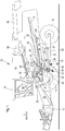
- FIG. 1 shows a self-propelled combine harvester 10 with a frame 12 which is supported by driven front wheels 14 and steerable rear wheels 16 on the ground and is moved away from them.
- the wheels 14 are rotated by means not shown drive means in rotation to the combine 10 z. B. to move over a field to be harvested.
- directional details such as front and rear, refer to the direction of travel V of the combine harvester 10 in harvesting operation.
- a crop gathering device 18 is detachably connected in the form of a cutter to harvest harvested crops in the form of crops or other threshable culottes from the field and feed them up and down by a feeder 20 to a multi-drum threshing unit.
- a threshing cylinder 22 arranged one behind the other - a threshing cylinder 22, a stripping drum 24, a superseding working conveyor drum 26, a Tangentialseparator 28 and a turning drum 30 includes.
- Downstream of the turning drum 30 is a straw shaker 32 with a plurality of laterally juxtaposed Horden thoroughemper.
- the threshing cylinder 22 is surrounded in its lower and rearward area by a concave 34.
- a finger rake 38 is arranged below the conveyor drum 26.
- a front conveyor floor 40 which performs in operation in an alternately forward and rearward swinging movement.
- a rear conveyor floor 42 is disposed below the straw walker 32 and performs in operation also alternately backwards and forwards directed swinging motion.
- the front conveyor floor 40 transports the mixture of grain and chaff down through the threshing basket 34 and through the separating basket 36 of the tangential separator 28 to the rear, while the rear conveyor floor 42 transports the mixture of grain and chaff flowing through the straw shaker 32 forwards ,
- the rear conveyor bottom 42 passes its mixture at its front end to the front conveyor bottom 40, which emits it by a rear finger rake 44 down.
- the mixture discharged from the front conveyor bottom 40 then passes into a cleaning device 46.
- Grain cleaned by the cleaning device 46 is fed by means of a grain screw 48 to an elevator, not shown, which transports it to a grain tank 50.
- a tailing auger 52 returns unmanaged ear parts through another elevator, not shown, back into the threshing process.
- the chaff may be ejected at the rear of the screen by a rotating chaff spreader, or it may be discharged through a straw chopper (not shown) disposed downstream of the straw walker 32.
- the cleaned grain from the grain tank 50 may be unloaded by a discharge system with cross augers 54 and a discharge conveyor 56.
- the systems mentioned are driven by means of an internal combustion engine 58 and controlled and controlled by an operator from a driver's cab 60.
- the various devices for threshing, conveying, cleaning and separating are located within the frame 12. Outside the frame 12 is an outer shell, which is largely hinged.
- multi-drum thresher shown here is only one embodiment. It could also be replaced by a single transverse threshing cylinder and a downstream separator with a straw walker or one or more separation rotors.
- the cleaning device 46 comprises a fan 62, which consists of one in rotation (in the FIG. 2 counterclockwise) 64 and a rotor 64 enclosing housing 66 composed. Furthermore, the cleaning device 46 comprises a Vorthesessieb 72 with supported in a sieve frame, there adjustable about its longitudinal axis at an angle Sieblamellen, which is located below the Fingerrechens 44 and extends approximately from the rear edge of the front conveyor floor 40 horizontally backwards and slightly upwards ,
- Vorthesessiebs 72 Below the front half of Vorthesessiebs 72 is a conveyor bottom 80, below which in turn the upper part of the housing 66 of the blower 62 is arranged. At the rear of the conveyor floor is a grate 96 followed by a top wire 90 and a bottom wire 92 arranged below it.
- the upper sieve 90 and the lower sieve 92 each comprise sieve blades which are arranged in a frame and are adjustable independently of one another at an angle about their longitudinal axis. Further details of the cleaning device 46 are the DE 10 2005 026 608 A1 removable. It can also find any other cleaning facilities use.
- the preliminary screen 72 could be replaced by a conveyor bottom or screw conveyor.
- a grain flow sensor 68 is provided which is located below the front end of a return trough 70, which is located below the rear of the straw shaker 32 and serves to deposited there grain to the conveyor bottom 42 to promote.
- the grain flow sensor 68 is located within a drop stage that traverses the grain between the return trough 70 and the conveyor bottom 42. Bouncing grains thus cause well detectable vibrations on the grain flow sensor 68, which may be a conventional baffle plate sensor.
- An additional or alternatively provided grain flow sensor 68 ' is located within the conveying floor 42, in particular approximately at the beginning of the rear third.
- the grain flow sensor 68 'lies in the plane of the conveying floor 42 and detects the vibrations caused by the grains impinging on it during the conveying process. It can also be designed as a baffle plate sensor.
- An additional or alternatively provided grain flow sensor 68 is located within a step that traverses the grain between the conveyor bottom 42 and the front conveyor bottom 40. Bouncing grains on the grain flow sensor 68", which may also be a conventional baffle plate sensor, thus cause well detectable vibrations ,
- the grain stream sensors 68, 68 'and / or 68 are signal transmitting connected to a control unit 74, which in turn is connected to a display unit 76.
- the control unit 74 is also connected to a Rescuekornchensensor 78, which is assigned in the illustrated embodiment of the grain screw 48 and her
- the total grain flow sensor 78 could sense the grain flow through light barriers in the grain elevator (not shown) located between the grain screw 48 and the grain tank 50.
- the control unit 74 receives signals from one or more of the grain flow sensors 68, 68 'and / or 68 "in harvesting mode. These signals are from a relatively large flow of grain integrated by the return trough 70 and the conveyor bottom 42 upstream, downstream or within the rear The control unit 74 is thus supplied with signals regarding the grain deposited in the rear third (grain flow sensor 68) or in the rear two thirds (grain flow sensor 68 ') or in the entire straw shaker 32 (grain flow sensor 68 "). These signals are converted by the control unit 74 into loss values.
- associated loss curves from a memory of the control unit 74 can be called up for different total grain flows detected with the total grain flow sensor 78 and the current loss value for the signal of the grain flow sensor 68, 68 'or 68 "is read from the respective valid loss curve and displayed on the display unit 76.
- the control device 74 may be connected to two grain flow sensors (eg 68 on the one hand and 68 'and / or 68 "on the other hand or 68' on the one hand and 68" on the other hand) based on the signals of the different ones Corner current sensors generate a deposition curve and on the basis of the deposition curve a loss value US 4 951 031 A and DE 101 62 354 A1 directed.
- control unit 74 in addition to conventional loss sensors for the To connect cleaning to also display the cleaning losses (and / or a cumulative loss value) on the display unit 76 can.
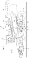
- a concave 132 and below the separating section 128, a separation grate 134 is arranged below the threshing section 126.
- a screw conveyor 140 conveys the grain falling downward through the concave 132 to the rear and to the pre-cleaning screen 72, while the rear conveyor floor 42 conveys the crop falling down through the separating rack 134 forward, and to a case where a grain flow sensor 68a is disposed , emits on the Vorthesessieb 72.
- Another or alternative grain flow sensor 68b is mounted in the rear third of the conveyor floor 42, analogous to the grain flow sensor 68 'of FIG FIG. 1 ,
- the grain stream sensor 68a detects the entire grain flow separated by the separator formed by the separation section 128 and the separation grate 134.
- the grain flow sensor 68b approximately detects the grain stream deposited in the rear third of the separator.
- the operation of the loss measurement device with the control unit 74, the display device 76, the grain flow sensor 68a and / or 68b, and the total grain flow sensor 78 is the same as that of the embodiment of FIG. 1 ,
Landscapes
- Life Sciences & Earth Sciences (AREA)
- Environmental Sciences (AREA)
- Threshing Machine Elements (AREA)
Description
Die Erfindung betrifft einen Mähdrescher mit einer Drescheinrichtung, einer Trenneinrichtung, einer Reinigungseinrichtung, einer Fördereinrichtung für Korn, welche das von der Trenneinrichtung abgeschiedene Material sammelt und es zur Reinigungseinrichtung transportiert und einer Anordnung zur Verlustmessung, welche mit einem Körnerstromsensor zur Erfassung der Intensität eines in der Trenneinrichtung des Mähdreschers abgeschiedenen Körnerstroms und einer Kontrolleinheit zur Berechnung eines Körnerverlustwerts anhand der Signale des Körnerstromsensors ausgestattet ist.The invention relates to a combine harvester with a threshing device, a separator, a cleaning device, a conveyor for grain, which collects the separated material from the separator and transported it to the cleaning device and a loss measurement arrangement, which with a grain flow sensor for detecting the intensity of in the Separator of the combine harvester separated grain and a control unit is provided for calculating a grain loss value from the signals of the grain flow sensor.
Landwirtschaftliche Mähdrescher dienen zur Ernte von Getreide und anderen Körnern. Auf einem Feld stehende oder liegende Pflanzen werden mittels eines Erntevorsatzes abschnitten oder aufgenommen und mittels eines Schrägförderers in das Innere des Mähdreschers transportiert. Dort werden die Pflanzen gedroschen und einem Trennsystem zugeführt. Im Dresch- oder Trennprozess abgeschiedenes Korn wird in einem Reinigungssystem gereinigt und temporär in einem Korntank abgelegt, um es später auf ein Transportfahrzeug zu überladen.Agricultural combines are used to harvest grain and other grains. On a field standing or lying plants are cut off or picked up by means of a header and transported by means of an inclined conveyor into the interior of the combine. There, the plants are threshed and fed to a separation system. Grain deposited in the threshing or separating process is cleaned in a cleaning system and temporarily deposited in a grain tank for later transfer to a transport vehicle.
Der Dreschprozess erfolgt üblicherweise mittels einer Tangentialdreschtrommel oder im Dreschabschnitt eines axialen Dresch- und Trennrotors. Der Trennprozess erfolgt in der Regel mittels Trenntrommeln und einem Strohschüttler eines tangentialen Mehrtrommeldreschwerks oder eines stromab eines Tangentialdreschwerks angeordneten Trennrotors oder im Trennabschnitt eines axialen Dresch- und Trennrotors. Am Ende des Trennprozesses wird das ausgedroschene Stroh entweder in einem Schwad auf dem Feld abgelegt, um es später mit einer Ballenpresse aufzunehmen und zu Ballen zu pressen oder es wird durch einen Strohhäcksler geleitet, um schließlich über die Breite des Erntevorsatzes auf dem Feld verteilt zu werden.The threshing process usually takes place by means of a tangential threshing drum or in the threshing section of an axial threshing and separating rotor. The separation process is usually carried out by means of separating drums and a straw shaker of a tangential Mehrtrommeldreschwerks or downstream of a Tangentialdreschwerks arranged separation rotor or in the separation section of an axial threshing and separation rotor. At the end of the separation process, the threshed straw is either placed in a swath on the field for later baling and baling, or passed through a straw chopper and finally spread across the width of the header on the field ,
Beim Trennprozess verbleibt ein gewisser Anteil an Korn im Stroh und wird auf das Feld ausgeworfen. Dabei entstehen einerseits unerwünschte, den Ertrag mindernde Verluste und andererseits später zu bekämpfender Pflanzenwuchs durch keimendes Korn. Es ist daher wünschenswert, die Menge an Verlustkorn im Stroh am Ende des Trennprozesses zu erfassen, um ggf. Gegenmaßnahmen treffen zu können, wie eine Verminderung der Fahrgeschwindigkeit oder geänderte Einstellungen der Dresch- und/oder Trenneinrichtung. Im Stand der Technik wird für diesen Zweck am rückwärtigen Ende des Strohschüttlers ein Prallplattensensor angebracht (
Die
Die
Die der Erfindung zu Grunde liegende Aufgabe wird darin gesehen, eine Anordnung zur Verlustmessung in einem Mähdrescher bereitzustellen, welche die erwähnten Probleme nicht oder in vermindertem Maße aufweist.The object underlying the invention is seen to provide an arrangement for loss measurement in a combine harvester, which does not have the problems mentioned or to a lesser extent.
Diese Aufgabe wird erfindungsgemäß durch die Lehre des Patentanspruchs 1 gelöst, wobei in den weiteren Patentansprüchen Merkmale aufgeführt sind, die die Lösung in vorteilhafter Weise weiterentwickeln.This object is achieved by the teaching of claim 1, wherein in the other claims features are listed, which further develop the solution in an advantageous manner.
Eine Anordnung zur Verlustmessung in einem Mähdrescher umfasst einen Körnerstromsensor zur Erfassung der Intensität eines in einer Trenneinrichtung des Mähdreschers abgeschiedenen Körnerstroms und eine Kontrolleinheit zur Berechnung eines Körnerverlustwerts anhand der Signale des Körnerstromsensors. Der Körnerstromsensor ist einer zwischen der Trenneinrichtung und einer Reinigungseinrichtung angeordneten Fördereinrichtung für Korn zugeordnet.An arrangement for loss measurement in a combine comprises a grain flow sensor for detecting the intensity of a grain flow deposited in a separator of the combine and a control unit for calculating a grain loss value from the signals of the grain flow sensor. The grain flow sensor is assigned to a conveying device for grain arranged between the separating device and a cleaning device.
Die Fördereinrichtung sammelt das von der Trenneinrichtung abgeschiedene Material (Korn) und transportiert es zu einem einlassseitigen, als Vorsieb, Förderboden oder Schneckenförderer ausgeführten Element der Reinigungseinrichtung. In einem Abschnitt des Wegs desThe conveyor collects the separated material from the separator (grain) and transports it to an inlet side of the cleaning device designed as a pre-screening, conveying floor or screw conveyor. In a section of the way of the
Materials durch die Fördereinrichtung ist der Körnerstromsensor angeordnet. Der Körnerstromsensor erfasst somit das gesammelte Material, das durch die Fördereinrichtung von der Trenneinrichtung zur Reinigungseinrichtung gefördert wird. Auf diese Weise erreicht man, dass der Körnerstromsensor einem größeren Materialstrom ausgesetzt ist als im Stand der Technik, in dem er nur die Verluste am Auslass der Trenneinrichtung oder nur einen direkt von der Trenneinrichtung auf ihn treffenden Materialstrom erfasst. Somit wird durch den Körnerstromsensor ein größeres und zuverlässigeres Signal bereitgestellt, das die Bestimmung und Anzeige eines zuverlässigeren Verlustwerts als bisher ermöglicht.Material by the conveyor, the grain flow sensor is arranged. The grain flow sensor thus detects the collected material, which is conveyed by the conveyor from the separator to the cleaning device. In this way it is achieved that the grain flow sensor is exposed to a larger flow of material than in the prior art, in which it detects only the losses at the outlet of the separator or only one directly from the separator to him striking material flow. Thus, the grain current sensor provides a larger and more reliable signal that allows for the determination and display of a more reliable loss value than heretofore.
Der Körnerstromsensor erfasst den Körnerstrom stromab der Fördereinrichtung oder innerhalb der Fördereinrichtung. Insbesondere kann er stromab oder innerhalb eines Förderbodens oder einer Rücklaufwanne der Trenneinrichtung angeordnet werden. Die Trenneinrichtung kann einen Strohschüttler oder einen Trennrotor umfassen.The grain flow sensor detects the grain flow downstream of the conveyor or within the conveyor. In particular, it can be arranged downstream or inside a conveying floor or a return trough of the separating device. The separating device may comprise a straw shaker or a separating rotor.
Vorzugsweise ist die Kontrolleinrichtung mit einem Gesamtkornflusssensor zur Erfassung des gesamten Kornflusses im Mähdrescher verbunden und bestimmt den Körnerverlustwert anhand der Signale des Körnerstromsensors und des Gesamtkornflusssensors. Dazu können in der Kontrolleinheit für unterschiedliche Gesamtkornflüsse jeweils zugehörige Verlustkurven oder -tabellen abgespeichert sein, anhand derer die Kontrolleinheit bei gegebenem vom Körnerstromsensor erfasstem Körnerstrom den jeweiligen Verlust bestimmen kann.Preferably, the control means is connected to a total grain flow sensor for detecting the total grain flow in the combine and determines the grain loss value from the signals of the grain flow sensor and the total grain flow sensor. For this purpose, respective loss curves or tables can be stored in the control unit for different total grain flows, by means of which the control unit can determine the respective loss for a given grain flow detected by the grain flow sensor.
In den Zeichnungen sind zwei nachfolgend näher beschriebene Ausführungsbeispiele der Erfindung dargestellt. Es zeigt:
- Fig. 1
- eine schematische seitliche Ansicht einer ersten Ausführungsform eines Mähdreschers mit einer erfindungsgemäßen Anordnung zur Verlustmessung, und
- Fig. 2
- eine schematische seitliche Ansicht einer zweiten Ausführungsform eines Mähdreschers mit einer erfindungsgemäßen Anordnung zur Verlustmessung.
- Fig. 1
- a schematic side view of a first embodiment of a combine with an inventive arrangement for loss measurement, and
- Fig. 2
- a schematic side view of a second embodiment of a combine with an inventive arrangement for loss measurement.
Die
im Erntebetrieb.The
in harvesting operation.
An den vorderen Endbereich des Mähdreschers 10 ist eine Erntegutbergungsvorrichtung 18 in Form eines Schneidwerks abnehmbar angeschlossen, um beim Erntebetrieb Erntegut in Form von Getreide oder andere, dreschbare Halmfrüchten von dem Feld zu ernten und es nach oben und hinten durch einen Schrägförderer 20 einem Mehrtrommeldreschwerk zuzuführen, das - in Fahrtrichtung V hintereinander angeordnet - eine Dreschtrommel 22, eine Abstreiftrommel 24, eine oberschlächtig arbeitende Fördertrommel 26, einen Tangentialseparator 28 sowie eine Wendetrommel 30 umfasst. Stromab der Wendetrommel 30 befindet sich ein Strohschüttler 32 mit mehreren, seitlich nebeneinander angeordneten Hordenschüttlern. Die Dreschtrommel 22 ist in ihrem unteren und rückwärtigen Bereich von einem Dreschkorb 34 umgeben. Unterhalb der Fördertrommel 26 ist eine mit Öffnungen versehene oder geschlossene Abdeckung 35 angeordnet, während sich oberhalb der Fördertrommel 26 eine fest stehende Abdeckung und unterhalb des Tangentialseparators 28 ein Separierkorb 36 mit verstellbaren Fingerelementen befindet. Unterhalb der Wendetrommel 30 ist ein Fingerrechen 38 angeordnet.At the front end portion of the
Unterhalb des Mehrtrommeldreschwerks befindet sich ein vorderer Förderboden 40, der im Betrieb in eine abwechselnd nach vorn und hinten gerichtete Schwingbewegung durchführt. Ein hinterer Förderboden 42 ist unterhalb des Strohschüttlers 32 angeordnet und vollführt im Betrieb ebenfalls eine abwechselnd nach hinten und vorn gerichtete Schwingbewegung. Der vordere Förderboden 40 transportiert das durch den Dreschkorb 34 und durch den Separierkorb 36 des Tangentialseparators 28 nach unten hindurch tretende Gemisch aus Korn und Spreu nach hinten, während der hintere Förderboden 42 das durch den Strohschüttler 32 hindurch strömende Gemisch aus Korn und Spreu nach vorn transportiert. Der hintere Förderboden 42 übergibt sein Gemisch an seinem vorderen Ende an den vorderen Förderboden 40, der es durch einen rückwärtigen Fingerrechen 44 nach unten abgibt. Das vom vorderen Förderboden 40 abgegebene Gemisch gelangt dann in eine Reinigungseinrichtung 46.Below the multi-drum thresher is a
Durch die Reinigungseinrichtung 46 gereinigtes Getreide wird mittels einer Körnerschnecke 48 einem nicht gezeigten Elevator zugeführt, der es in einen Korntank 50 befördert. Eine Überkehrschnecke 52 gibt unausgedroschene Ährenteile durch einen weiteren nicht gezeigten Elevator zurück in den Dreschprozess. Die Spreu kann an der Rückseite der Siebeinrichtung durch einen rotierenden Spreuverteiler ausgeworfen werden, oder sie wird durch einen stromab des Strohschüttlers 32 angeordneten Strohhäcksler (nicht eingezeichnet) ausgetragen. Das gereinigte Getreide aus dem Korntank 50 kann durch ein Entladesystem mit Querschnecken 54 und einem Entladeförderer 56 entladen werden.Grain cleaned by the
Die genannten Systeme werden mittels eines Verbrennungsmotors 58 angetrieben und von einem Bediener aus einer Fahrerkabine 60 heraus kontrolliert und gesteuert. Die verschiedenen Vorrichtungen zum Dreschen, Fördern, Reinigen und Abscheiden befinden sich innerhalb des Rahmens 12. Außerhalb des Rahmens 12 befindet sich eine Außenhülle, die größtenteils aufklappbar ist.The systems mentioned are driven by means of an
Es bleibt anzumerken, dass das hier dargestellte Mehrtrommeldreschwerk nur ein Ausführungsbeispiel ist. Es könnte auch durch eine einzige quer angeordnete Dreschtrommel und eine nachgeordnete Trenneinrichtung mit einem Strohschüttler oder einem oder mehreren Trennrotoren ersetzt werden.It should be noted that the multi-drum thresher shown here is only one embodiment. It could also be replaced by a single transverse threshing cylinder and a downstream separator with a straw walker or one or more separation rotors.
Die Reinigungseinrichtung 46 umfasst ein Gebläse 62, das sich aus einem in Drehung (in der
Unterhalb der vorderen Hälfte des Vorreinigungssiebs 72 befindet sich ein Förderboden 80, unter dem wiederum der obere Teil des Gehäuses 66 des Gebläses 62 angeordnet ist. Rückwärtig des Förderbodens ist ein Rost 96, dem ein Obersieb 90 und ein darunter angeordnetes Untersieb 92 folgt. Das Obersieb 90 und das Untersieb 92 umfassen jeweils in einem Rahmen angeordnete, um ihre Längsachse im Winkel unabhängig voneinander verstellbare Sieblamellen. Weitere Einzelheiten der Reinigungseinrichtung 46 sind der
Um die Verluste in der Trenneinrichtung, die bei der Ausführungsform nach
Ein zusätzlicher oder alternativ vorgesehener Körnerstromsensor 68' befindet sich innerhalb des Förderbodens 42, insbesondere etwa am Anfang des rückwärtigen Drittels. Der Körnerstromsensor 68' liegt in der Ebene des Förderbodens 42 und erfasst die beim Fördervorgang durch auf ihn aufprallende Körner verursachten Schwingungen. Er kann ebenfalls als Prallplattensensor ausgebildet sein.An additional or alternatively provided grain flow sensor 68 'is located within the conveying
Ein zusätzlicher oder alternativ vorgesehener Körnerstromsensor 68" befindet sich innerhalb einer Fallstufe, die das Korn zwischen dem Förderboden 42 und dem vorderen Förderboden 40 zurücklegt. Aufprallende Körner verursachen auf dem Körnerstromsensor 68", der ebenfalls als konventioneller Prallplattensensor ausgebildet sein kann, somit gut nachweisbare Schwingungen.An additional or alternatively provided
Die Körnerstromsensoren 68, 68' und/oder 68" sind signalübertragend mit einer Kontrolleinheit 74 verbunden, die ihrerseits mit einer Anzeigeneinheit 76 verbunden ist. Die Kontrolleinheit 74 ist außerdem mit einem Gesamtkornflusssensor 78 verbunden, der im dargestellten Ausführungsbeispiel der Körnerschnecke 48 zugeordnet ist und ihr Antriebsmoment erfasst. Der Gesamtkornflusssensor 78 könnte bei einer anderen Ausführungsform den Kornfluss durch Lichtschranken im Körnerelevator (nicht gezeigt) erfassen, der sich zwischen der Körnerschnecke 48 und dem Korntank 50 befindet.The
Die Kontrolleinheit 74 erhält im Erntebetrieb Signale von einem oder mehreren der Körnerstromsensoren 68, 68' und/oder 68". Diese Signale werden von einem relativ großen, durch die Rücklaufwanne 70 und den Förderboden 42 integrierten Fluss des Korns stromauf, stromab oder innerhalb des hinteren Förderbodens 42 generiert und sind daher recht zuverlässig. Die Kontrolleinheit 74 wird somit mit Signalen hinsichtlich der im hinteren Drittel (Körnerstromsensor 68) oder in den hinteren zwei Dritteln (Körnerstromsensor 68') oder im gesamten Strohschüttler 32 (Körnerstromsensor 68") abgeschiedenen Korns beaufschlagt. Diese Signale werden durch die Kontrolleinheit 74 in Verlustwerte umgerechnet. Dazu können für unterschiedliche Gesamtkornflüsse, die mit dem Gesamtkornflusssensor 78 erfasst werden, zugehörige Verlustkurven aus einem Speicher der Kontrolleinheit 74 abgerufen werden und der aktuelle Verlustwert für das Signal des Körnerstromsensors 68, 68' oder 68" aus der jeweils gültigen Verlustkurve ausgelesen und auf der Anzeigeneinheit 76 dargestellt werden. Alternativ oder zusätzlich kann die Kontrolleinrichtung 74 mit zwei an unterschiedlichen Stellen der Fördereinrichtung angeordneten Körnerstromsensoren (z.B. 68 einerseits und 68' und/oder 68" andererseits oder 68' einerseits und 68" andererseits) verbunden werden und anhand der Signale der unterschiedlichen Körnerstromsensoren eine Abscheidekurve und anhand der Abscheidekurve einen Verlustwert generieren. Hierzu sei auf den Stand der Technik nach
Es wäre auch denkbar, die Kontrolleinheit 74 zusätzlich mit konventionellen Verlustsensoren für die Reinigung zu verbinden, um auch die Reinigungsverluste (und/oder einen kumulierten Verlustwert) auf der Anzeigeneinheit 76 anzeigen zu können.It would also be conceivable, the
Bei der Ausführungsform des Mähdreschers 10' nach
Unterhalb des Dreschabschnitts 126 ist ein Dreschkorb 132 und unterhalb des Trennabschnitts 128 ein Trennrost 134 angeordnet. Ein Schneckenförderer 140 fördert das durch den Dreschkorb 132 nach unten fallende Korn nach hinten und auf das Vorreinigungssieb 72, während der hintere Förderboden 42 das durch den Trennrost 134 nach unten fallende Erntegut nach vorn fördert und in einer Fallstufe, in der ein Körnerstromsensor 68a angeordnet ist, auf das Vorreinigungssieb 72 abgibt. Ein weiterer oder alternativer Körnerstromsensor 68b ist im rückwärtigen Drittel des Förderbodens 42 angebracht, analog zum Körnerstromsensor 68' der
Bei dieser Ausführungsform erfasst der Körnerstromsensor 68a somit den gesamten, von der Trenneinrichtung, die durch den Trennabschnitt 128 und den Trennrost 134 gebildet wird, abgeschiedenen Körnerstrom. Der Körnerstromsensor 68b erfasst näherungsweise den im hinteren Drittel der Trenneinrichtung abgeschiedenen Körnerstrom. Die Funktionsweise der Anordnung zur Verlustmessung mit der Kontrolleinheit 74, der Anzeigeneinrichtung 76, dem Körnerstromsensor 68a und/oder 68b und dem Gesamtkornflusssensor 78 entspricht jener der Ausführungsform nach
Claims (5)
- Combine harvester (10) having:a threshing device,a separating device,a cleaning device (46), which comprises an inlet-side element which is embodied as a pre-conveyor (72), floor or worm conveyor, downstream of which screens (90, 92) to which a stream of air is supplied by a blower (62) are arranged,a front conveyor for grain which is arranged underneath the threshing device and adapted to collect material which is separated off by the threshing device and to feed said material to the inlet-side element of the cleaning device (46),a rear conveyor device for grain, which device is adapted to collect material which is separated off by the separating device and to convey said material to the front conveyor or to the inlet-side element of the cleaning device (46),and an arrangement for loss measurement, which arrangement is equipped with a grain flow sensor (68, 68', 68", 68a, 68b) for sensing the intensity of a grain flow which is separated off in the separating device of the combine harvester (10, 10'), and a control unit (74) for calculating a grain loss value on the basis of the signals of the grain flow sensor (68, 68', 68", 68a, 68b),wherein the grain flow sensor (68, 68', 68", 68a, 68b) is assigned to the rear conveyor device and configured to sense the grain flow downstream of the rear conveyor device or within the rear conveyor device.
- Combine harvester (10) according to Claim 1, wherein the grain flow sensor (68, 68', 68", 68a, 68b) is arranged downstream or within a conveyor floor (42) or a return pan (70) of the separating device.
- Combine harvester (10) according to Claim 2, wherein the separating device comprises a straw walker (32) or a separating rotor.
- Combine harvester (10) according to one of Claims 1 to 3, wherein the control device (74) is connected to a total grain flow sensor (78) for sensing the total grain flow in the combine harvester (10, 10') and can be operated to determine the grain loss value on the basis of the signals of the grain flow sensor (68, 68', 68", 68a, 68b) and of the total grain flow sensor (78).
- Combine harvester (10) according to one of Claims 1 to 4, wherein the control device (74) is connected to two grain flow sensors (68, 68', 68", 68a, 68b) which are arranged at different locations on the rear conveyor device and can be operated to generate a separation curve on the basis of the signals of the grain flow sensors (68, 68', 68", 68a, 68b), and a loss value on the basis of the separation curve.
Applications Claiming Priority (1)
| Application Number | Priority Date | Filing Date | Title |
|---|---|---|---|
| DE102013214984.0A DE102013214984A1 (en) | 2013-07-31 | 2013-07-31 | Arrangement for loss measurement in a combine harvester |
Publications (2)
| Publication Number | Publication Date |
|---|---|
| EP2845461A1 EP2845461A1 (en) | 2015-03-11 |
| EP2845461B1 true EP2845461B1 (en) | 2018-01-10 |
Family
ID=50943210
Family Applications (1)
| Application Number | Title | Priority Date | Filing Date |
|---|---|---|---|
| EP14172884.0A Active EP2845461B1 (en) | 2013-07-31 | 2014-06-18 | Assembly for measuring loss in a combine harvester |
Country Status (3)
| Country | Link |
|---|---|
| US (1) | US20150080069A1 (en) |
| EP (1) | EP2845461B1 (en) |
| DE (1) | DE102013214984A1 (en) |
Families Citing this family (10)
| Publication number | Priority date | Publication date | Assignee | Title |
|---|---|---|---|---|
| US9345197B2 (en) * | 2013-05-10 | 2016-05-24 | Agco Corporation | Combine harvester with even crop distribution |
| US10334781B2 (en) * | 2015-08-20 | 2019-07-02 | Cnh Industrial America Llc | Side shake rate based on machine throughputs |
| US10729065B2 (en) * | 2015-09-10 | 2020-08-04 | Deere & Company | Augmented crop loss sensing |
| US10512217B2 (en) | 2017-08-23 | 2019-12-24 | Deere & Company | Metering flow of grain to a cleaning device |
| US11083137B2 (en) * | 2018-05-01 | 2021-08-10 | Deere & Company | Return pan grain presentation to a sensor |
| GB201820714D0 (en) | 2018-12-19 | 2019-01-30 | Agco Int Gmbh | Grain cleaning system and method of controlling such |
| US12225849B2 (en) * | 2021-09-03 | 2025-02-18 | Cnh Industrial America Llc | Active loss monitor for a harvester |
| DE102022116228A1 (en) * | 2022-06-29 | 2024-01-04 | Deere & Company | Sensor arrangement for detecting properties of a mixture containing grain and impurities in a cleaning device of a combine harvester |
| US12310285B2 (en) | 2023-02-27 | 2025-05-27 | Deere & Company | Agricultural operation evaluation system and method |
| DE102023110536A1 (en) * | 2023-04-25 | 2024-10-31 | Deere & Company | sensor arrangement for a combine harvester |
Family Cites Families (15)
| Publication number | Priority date | Publication date | Assignee | Title |
|---|---|---|---|---|
| GB1157337A (en) * | 1966-12-05 | 1969-07-09 | Fortschritt Veb K | Methods Of, and Apparatus For, Measuring Grain Losses in Threshing Mechanisms |
| US3606745A (en) * | 1969-09-08 | 1971-09-21 | Massey Ferguson Ind Ltd | Grain flow rate monitor |
| FR2165441A5 (en) * | 1971-12-23 | 1973-08-03 | Fahr Ag Maschf | |
| US3939846A (en) * | 1974-06-27 | 1976-02-24 | Vladimir Kirillovich Drozhzhin | Device for monitoring and controlling the relative flows and losses of grain in a grain combine thresher |
| DE2448745C2 (en) | 1974-10-12 | 1982-09-02 | Gebr.Claas Maschinenfabrik GmbH, 4834 Harsewinkel | Sensor for measuring grain loss in combine harvesters |
| US4036065A (en) * | 1976-05-11 | 1977-07-19 | Senstek Ltd. | Grain loss monitor |
| US4230130A (en) * | 1979-02-05 | 1980-10-28 | International Harvester Company | Combine grain loss sensing |
| DE3850570T2 (en) | 1988-04-26 | 1994-10-20 | Ford New Holland Nv | Method and device for grain loss measurement on threshing machines. |
| US5046362A (en) * | 1988-04-26 | 1991-09-10 | Ford New Holland, Inc. | Grain loss monitors for harvesting machines |
| DE10162354A1 (en) | 2001-12-18 | 2003-07-03 | Claas Selbstfahr Erntemasch | Loss determination method on agricultural harvesters |
| DE102005026608A1 (en) | 2005-06-09 | 2007-01-04 | Deere & Company, Moline | Cleaning device for a combine harvester |
| GB0604860D0 (en) * | 2006-03-10 | 2006-04-19 | Cnh Belgium Nv | Improvements in or relating to material stream sensors |
| DE102007029218A1 (en) * | 2007-06-22 | 2008-12-24 | Claas Selbstfahrende Erntemaschinen Gmbh | Self-propelled agricultural harvester with loss meter |
| US8021219B2 (en) | 2007-10-31 | 2011-09-20 | Deere And Company | Top cover for axial rotary combine having coned transition |
| DE102011052282A1 (en) * | 2011-07-29 | 2013-01-31 | Claas Selbstfahrende Erntemaschinen Gmbh | Cleaning sensor for controlling crop and blower pressure distribution |
-
2013
- 2013-07-31 DE DE102013214984.0A patent/DE102013214984A1/en not_active Withdrawn
-
2014
- 2014-06-18 EP EP14172884.0A patent/EP2845461B1/en active Active
- 2014-07-31 US US14/448,754 patent/US20150080069A1/en not_active Abandoned
Non-Patent Citations (1)
| Title |
|---|
| None * |
Also Published As
| Publication number | Publication date |
|---|---|
| DE102013214984A1 (en) | 2015-02-05 |
| US20150080069A1 (en) | 2015-03-19 |
| EP2845461A1 (en) | 2015-03-11 |
Similar Documents
| Publication | Publication Date | Title |
|---|---|---|
| EP2845461B1 (en) | Assembly for measuring loss in a combine harvester | |
| EP3662741B1 (en) | Agricultural machine and method for operating an agricultural machine | |
| EP2761984B1 (en) | Vibration pick-up unit | |
| EP2517549B1 (en) | Assembly and method for detecting the quantity of plants on a field | |
| EP1350424B1 (en) | Harvester combine with motorized straw guiding device | |
| DE102008006882B4 (en) | Harvesting machine combination for plant residue utilization | |
| DE60021711T2 (en) | Condenser for harvesting device | |
| EP1344444B1 (en) | Device for detecting the presence of a flow in a harvesting machine | |
| EP2591654B1 (en) | Assembly and method for automatic documentation of situations in agricultural work | |
| DE102008043377A1 (en) | Measuring arrangement for the spectroscopic examination and throughput detection of a crop stream | |
| EP3597027B1 (en) | Combine with an inclined conveyor with lower deflection roller adjusted by means of an actuator | |
| DE102007046678A1 (en) | Agricultural work vehicle | |
| EP1862055A2 (en) | Distribution device for distributing crops being discharged from a harvester | |
| EP3797575B1 (en) | Combine harvester with driver assistance system | |
| DE3709242A1 (en) | CLEANING DEVICE FOR COMBINATION | |
| EP2848113B1 (en) | Cleaning device for a combine | |
| EP2774474B1 (en) | Combine harvester | |
| EP3797577B1 (en) | Combine harvester with residual grain sensor | |
| EP3072378B1 (en) | Grain flow sensor assembly for a combine harvester | |
| DE1965025B1 (en) | Arrangement for re-threshing the goods which have not been threshed through the cleaning device of a threshing machine or a combine harvester | |
| EP4442102A1 (en) | Method and arrangement for the computer-assisted processing of an electronic yield map | |
| DE10359398B3 (en) | Harvested crop recovery device for combine harvester with adjustable stripping elements on either side positioned for uniform distribution of harvested crop across width of delivery channel | |
| DE102021110556A1 (en) | Combine harvester and method for operating a combine harvester | |
| EP1576869A1 (en) | Measuring device or measuring superficial humidity | |
| DE102024118178A1 (en) | Sensor arrangement for detecting grains in a material stream containing grains and non-grain components in a combine harvester |
Legal Events
| Date | Code | Title | Description |
|---|---|---|---|
| 17P | Request for examination filed |
Effective date: 20140618 |
|
| AK | Designated contracting states |
Kind code of ref document: A1 Designated state(s): AL AT BE BG CH CY CZ DE DK EE ES FI FR GB GR HR HU IE IS IT LI LT LU LV MC MK MT NL NO PL PT RO RS SE SI SK SM TR |
|
| AX | Request for extension of the european patent |
Extension state: BA ME |
|
| PUAI | Public reference made under article 153(3) epc to a published international application that has entered the european phase |
Free format text: ORIGINAL CODE: 0009012 |
|
| R17P | Request for examination filed (corrected) |
Effective date: 20150911 |
|
| RBV | Designated contracting states (corrected) |
Designated state(s): AL AT BE BG CH CY CZ DE DK EE ES FI FR GB GR HR HU IE IS IT LI LT LU LV MC MK MT NL NO PL PT RO RS SE SI SK SM TR |
|
| 17Q | First examination report despatched |
Effective date: 20160509 |
|
| GRAP | Despatch of communication of intention to grant a patent |
Free format text: ORIGINAL CODE: EPIDOSNIGR1 |
|
| INTG | Intention to grant announced |
Effective date: 20170811 |
|
| GRAS | Grant fee paid |
Free format text: ORIGINAL CODE: EPIDOSNIGR3 |
|
| GRAA | (expected) grant |
Free format text: ORIGINAL CODE: 0009210 |
|
| AK | Designated contracting states |
Kind code of ref document: B1 Designated state(s): AL AT BE BG CH CY CZ DE DK EE ES FI FR GB GR HR HU IE IS IT LI LT LU LV MC MK MT NL NO PL PT RO RS SE SI SK SM TR |
|
| REG | Reference to a national code |
Ref country code: CH Ref legal event code: EP Ref country code: AT Ref legal event code: REF Ref document number: 961403 Country of ref document: AT Kind code of ref document: T Effective date: 20180115 |
|
| REG | Reference to a national code |
Ref country code: IE Ref legal event code: FG4D Free format text: LANGUAGE OF EP DOCUMENT: GERMAN |
|
| REG | Reference to a national code |
Ref country code: DE Ref legal event code: R096 Ref document number: 502014006869 Country of ref document: DE |
|
| REG | Reference to a national code |
Ref country code: NL Ref legal event code: MP Effective date: 20180110 |
|
| PG25 | Lapsed in a contracting state [announced via postgrant information from national office to epo] |
Ref country code: NL Free format text: LAPSE BECAUSE OF FAILURE TO SUBMIT A TRANSLATION OF THE DESCRIPTION OR TO PAY THE FEE WITHIN THE PRESCRIBED TIME-LIMIT Effective date: 20180110 |
|
| PG25 | Lapsed in a contracting state [announced via postgrant information from national office to epo] |
Ref country code: NO Free format text: LAPSE BECAUSE OF FAILURE TO SUBMIT A TRANSLATION OF THE DESCRIPTION OR TO PAY THE FEE WITHIN THE PRESCRIBED TIME-LIMIT Effective date: 20180410 Ref country code: LT Free format text: LAPSE BECAUSE OF FAILURE TO SUBMIT A TRANSLATION OF THE DESCRIPTION OR TO PAY THE FEE WITHIN THE PRESCRIBED TIME-LIMIT Effective date: 20180110 Ref country code: ES Free format text: LAPSE BECAUSE OF FAILURE TO SUBMIT A TRANSLATION OF THE DESCRIPTION OR TO PAY THE FEE WITHIN THE PRESCRIBED TIME-LIMIT Effective date: 20180110 Ref country code: HR Free format text: LAPSE BECAUSE OF FAILURE TO SUBMIT A TRANSLATION OF THE DESCRIPTION OR TO PAY THE FEE WITHIN THE PRESCRIBED TIME-LIMIT Effective date: 20180110 Ref country code: CY Free format text: LAPSE BECAUSE OF FAILURE TO SUBMIT A TRANSLATION OF THE DESCRIPTION OR TO PAY THE FEE WITHIN THE PRESCRIBED TIME-LIMIT Effective date: 20180110 Ref country code: FI Free format text: LAPSE BECAUSE OF FAILURE TO SUBMIT A TRANSLATION OF THE DESCRIPTION OR TO PAY THE FEE WITHIN THE PRESCRIBED TIME-LIMIT Effective date: 20180110 |
|
| PG25 | Lapsed in a contracting state [announced via postgrant information from national office to epo] |
Ref country code: GR Free format text: LAPSE BECAUSE OF FAILURE TO SUBMIT A TRANSLATION OF THE DESCRIPTION OR TO PAY THE FEE WITHIN THE PRESCRIBED TIME-LIMIT Effective date: 20180411 Ref country code: IS Free format text: LAPSE BECAUSE OF FAILURE TO SUBMIT A TRANSLATION OF THE DESCRIPTION OR TO PAY THE FEE WITHIN THE PRESCRIBED TIME-LIMIT Effective date: 20180510 Ref country code: PL Free format text: LAPSE BECAUSE OF FAILURE TO SUBMIT A TRANSLATION OF THE DESCRIPTION OR TO PAY THE FEE WITHIN THE PRESCRIBED TIME-LIMIT Effective date: 20180110 Ref country code: LV Free format text: LAPSE BECAUSE OF FAILURE TO SUBMIT A TRANSLATION OF THE DESCRIPTION OR TO PAY THE FEE WITHIN THE PRESCRIBED TIME-LIMIT Effective date: 20180110 Ref country code: SE Free format text: LAPSE BECAUSE OF FAILURE TO SUBMIT A TRANSLATION OF THE DESCRIPTION OR TO PAY THE FEE WITHIN THE PRESCRIBED TIME-LIMIT Effective date: 20180110 Ref country code: BG Free format text: LAPSE BECAUSE OF FAILURE TO SUBMIT A TRANSLATION OF THE DESCRIPTION OR TO PAY THE FEE WITHIN THE PRESCRIBED TIME-LIMIT Effective date: 20180410 Ref country code: RS Free format text: LAPSE BECAUSE OF FAILURE TO SUBMIT A TRANSLATION OF THE DESCRIPTION OR TO PAY THE FEE WITHIN THE PRESCRIBED TIME-LIMIT Effective date: 20180110 |
|
| PG25 | Lapsed in a contracting state [announced via postgrant information from national office to epo] |
Ref country code: MT Free format text: LAPSE BECAUSE OF FAILURE TO SUBMIT A TRANSLATION OF THE DESCRIPTION OR TO PAY THE FEE WITHIN THE PRESCRIBED TIME-LIMIT Effective date: 20180110 |
|
| REG | Reference to a national code |
Ref country code: DE Ref legal event code: R097 Ref document number: 502014006869 Country of ref document: DE |
|
| PG25 | Lapsed in a contracting state [announced via postgrant information from national office to epo] |
Ref country code: EE Free format text: LAPSE BECAUSE OF FAILURE TO SUBMIT A TRANSLATION OF THE DESCRIPTION OR TO PAY THE FEE WITHIN THE PRESCRIBED TIME-LIMIT Effective date: 20180110 Ref country code: AL Free format text: LAPSE BECAUSE OF FAILURE TO SUBMIT A TRANSLATION OF THE DESCRIPTION OR TO PAY THE FEE WITHIN THE PRESCRIBED TIME-LIMIT Effective date: 20180110 Ref country code: RO Free format text: LAPSE BECAUSE OF FAILURE TO SUBMIT A TRANSLATION OF THE DESCRIPTION OR TO PAY THE FEE WITHIN THE PRESCRIBED TIME-LIMIT Effective date: 20180110 |
|
| PLBE | No opposition filed within time limit |
Free format text: ORIGINAL CODE: 0009261 |
|
| STAA | Information on the status of an ep patent application or granted ep patent |
Free format text: STATUS: NO OPPOSITION FILED WITHIN TIME LIMIT |
|
| PG25 | Lapsed in a contracting state [announced via postgrant information from national office to epo] |
Ref country code: CZ Free format text: LAPSE BECAUSE OF FAILURE TO SUBMIT A TRANSLATION OF THE DESCRIPTION OR TO PAY THE FEE WITHIN THE PRESCRIBED TIME-LIMIT Effective date: 20180110 Ref country code: SM Free format text: LAPSE BECAUSE OF FAILURE TO SUBMIT A TRANSLATION OF THE DESCRIPTION OR TO PAY THE FEE WITHIN THE PRESCRIBED TIME-LIMIT Effective date: 20180110 Ref country code: DK Free format text: LAPSE BECAUSE OF FAILURE TO SUBMIT A TRANSLATION OF THE DESCRIPTION OR TO PAY THE FEE WITHIN THE PRESCRIBED TIME-LIMIT Effective date: 20180110 Ref country code: SK Free format text: LAPSE BECAUSE OF FAILURE TO SUBMIT A TRANSLATION OF THE DESCRIPTION OR TO PAY THE FEE WITHIN THE PRESCRIBED TIME-LIMIT Effective date: 20180110 |
|
| 26N | No opposition filed |
Effective date: 20181011 |
|
| REG | Reference to a national code |
Ref country code: CH Ref legal event code: PL |
|
| GBPC | Gb: european patent ceased through non-payment of renewal fee |
Effective date: 20180618 |
|
| PG25 | Lapsed in a contracting state [announced via postgrant information from national office to epo] |
Ref country code: SI Free format text: LAPSE BECAUSE OF FAILURE TO SUBMIT A TRANSLATION OF THE DESCRIPTION OR TO PAY THE FEE WITHIN THE PRESCRIBED TIME-LIMIT Effective date: 20180110 |
|
| REG | Reference to a national code |
Ref country code: IE Ref legal event code: MM4A |
|
| PG25 | Lapsed in a contracting state [announced via postgrant information from national office to epo] |
Ref country code: LU Free format text: LAPSE BECAUSE OF NON-PAYMENT OF DUE FEES Effective date: 20180618 Ref country code: MC Free format text: LAPSE BECAUSE OF FAILURE TO SUBMIT A TRANSLATION OF THE DESCRIPTION OR TO PAY THE FEE WITHIN THE PRESCRIBED TIME-LIMIT Effective date: 20180110 |
|
| PG25 | Lapsed in a contracting state [announced via postgrant information from national office to epo] |
Ref country code: GB Free format text: LAPSE BECAUSE OF NON-PAYMENT OF DUE FEES Effective date: 20180618 Ref country code: CH Free format text: LAPSE BECAUSE OF NON-PAYMENT OF DUE FEES Effective date: 20180630 Ref country code: IE Free format text: LAPSE BECAUSE OF NON-PAYMENT OF DUE FEES Effective date: 20180618 Ref country code: FR Free format text: LAPSE BECAUSE OF NON-PAYMENT OF DUE FEES Effective date: 20180630 Ref country code: LI Free format text: LAPSE BECAUSE OF NON-PAYMENT OF DUE FEES Effective date: 20180630 |
|
| PG25 | Lapsed in a contracting state [announced via postgrant information from national office to epo] |
Ref country code: TR Free format text: LAPSE BECAUSE OF FAILURE TO SUBMIT A TRANSLATION OF THE DESCRIPTION OR TO PAY THE FEE WITHIN THE PRESCRIBED TIME-LIMIT Effective date: 20180110 |
|
| PG25 | Lapsed in a contracting state [announced via postgrant information from national office to epo] |
Ref country code: HU Free format text: LAPSE BECAUSE OF FAILURE TO SUBMIT A TRANSLATION OF THE DESCRIPTION OR TO PAY THE FEE WITHIN THE PRESCRIBED TIME-LIMIT; INVALID AB INITIO Effective date: 20140618 Ref country code: PT Free format text: LAPSE BECAUSE OF FAILURE TO SUBMIT A TRANSLATION OF THE DESCRIPTION OR TO PAY THE FEE WITHIN THE PRESCRIBED TIME-LIMIT Effective date: 20180110 |
|
| PG25 | Lapsed in a contracting state [announced via postgrant information from national office to epo] |
Ref country code: MK Free format text: LAPSE BECAUSE OF NON-PAYMENT OF DUE FEES Effective date: 20180110 |
|
| REG | Reference to a national code |
Ref country code: AT Ref legal event code: MM01 Ref document number: 961403 Country of ref document: AT Kind code of ref document: T Effective date: 20190618 |
|
| PG25 | Lapsed in a contracting state [announced via postgrant information from national office to epo] |
Ref country code: AT Free format text: LAPSE BECAUSE OF NON-PAYMENT OF DUE FEES Effective date: 20190618 |
|
| PGFP | Annual fee paid to national office [announced via postgrant information from national office to epo] |
Ref country code: IT Payment date: 20220621 Year of fee payment: 9 |
|
| PG25 | Lapsed in a contracting state [announced via postgrant information from national office to epo] |
Ref country code: IT Free format text: LAPSE BECAUSE OF NON-PAYMENT OF DUE FEES Effective date: 20230618 |
|
| PGFP | Annual fee paid to national office [announced via postgrant information from national office to epo] |
Ref country code: DE Payment date: 20250521 Year of fee payment: 12 |
|
| PGFP | Annual fee paid to national office [announced via postgrant information from national office to epo] |
Ref country code: BE Payment date: 20250627 Year of fee payment: 12 |