EP1862055A2 - Distribution device for distributing crops being discharged from a harvester - Google Patents
Distribution device for distributing crops being discharged from a harvester Download PDFInfo
- Publication number
- EP1862055A2 EP1862055A2 EP07103435A EP07103435A EP1862055A2 EP 1862055 A2 EP1862055 A2 EP 1862055A2 EP 07103435 A EP07103435 A EP 07103435A EP 07103435 A EP07103435 A EP 07103435A EP 1862055 A2 EP1862055 A2 EP 1862055A2
- Authority
- EP
- European Patent Office
- Prior art keywords
- distributor according
- control
- machine housing
- inclination
- evaluation unit
- Prior art date
- Legal status (The legal status is an assumption and is not a legal conclusion. Google has not performed a legal analysis and makes no representation as to the accuracy of the status listed.)
- Granted
Links
- 238000009826 distribution Methods 0.000 title claims description 29
- 238000011156 evaluation Methods 0.000 claims description 28
- 239000000463 material Substances 0.000 claims description 16
- 230000001419 dependent effect Effects 0.000 claims description 2
- 238000005266 casting Methods 0.000 claims 1
- 239000002689 soil Substances 0.000 abstract description 8
- 230000008859 change Effects 0.000 abstract description 4
- 239000010902 straw Substances 0.000 description 16
- 238000003306 harvesting Methods 0.000 description 8
- 230000007480 spreading Effects 0.000 description 7
- 238000003892 spreading Methods 0.000 description 7
- 238000006073 displacement reaction Methods 0.000 description 6
- 230000000694 effects Effects 0.000 description 5
- 238000004140 cleaning Methods 0.000 description 4
- 238000005520 cutting process Methods 0.000 description 4
- 230000007246 mechanism Effects 0.000 description 2
- 239000000203 mixture Substances 0.000 description 2
- 238000002360 preparation method Methods 0.000 description 2
- 241001124569 Lycaenidae Species 0.000 description 1
- 239000000470 constituent Substances 0.000 description 1
- 230000008878 coupling Effects 0.000 description 1
- 238000010168 coupling process Methods 0.000 description 1
- 238000005859 coupling reaction Methods 0.000 description 1
- 230000008021 deposition Effects 0.000 description 1
- 238000011161 development Methods 0.000 description 1
- 238000000034 method Methods 0.000 description 1
- 238000012544 monitoring process Methods 0.000 description 1
- 230000008569 process Effects 0.000 description 1
- 238000000926 separation method Methods 0.000 description 1
- 239000000454 talc Substances 0.000 description 1
- 229910052623 talc Inorganic materials 0.000 description 1
- 230000032258 transport Effects 0.000 description 1
- 238000011144 upstream manufacturing Methods 0.000 description 1
Images

Classifications
-
- A—HUMAN NECESSITIES
- A01—AGRICULTURE; FORESTRY; ANIMAL HUSBANDRY; HUNTING; TRAPPING; FISHING
- A01D—HARVESTING; MOWING
- A01D41/00—Combines, i.e. harvesters or mowers combined with threshing devices
- A01D41/12—Details of combines
- A01D41/1243—Devices for laying-out or distributing the straw
Definitions
- the invention relates to a distribution device for distributing crop material emerging from a harvester according to the preamble of claim 1,
- a distributor for emerging from a harvester shredded material is from the DE 38 38 936 known.
- the distribution device is arranged behind a straw chopper and has adjustable baffles with which the chopped straw emerging from the straw chopper is deflected and stored in a distribution width in the field, the baffles are common depending on the determined by an inclination sensor slope transverse to the direction of the combine harvester automatically adjusted by a motor, in order to throw the harvested crop upwards along the slope during harvesting, and thus to prevent the shredded material from being thrown down into the valley,
- a disadvantage of this distribution device is that it can be used appropriately only in combine harvesters, in which the machine housing and / or the distribution device aligns at harvest time on a slope to the slope of the field and thus the distributor has a constant distance to the field soil.
- the distributor In Hangmähdreschern in which the machine housing and / or the distribution device is aligned with the crop ride on a slope with a slope compensation device to the vertical, the distributor has uphill a shorter distance and the valley side a greater distance from the field floor. These distances of the distribution device limit the trajectories of the crop. An adjustment of the spread in the direction of slope would cause the amount of crop, the slope before reaching the desired Spread on the impinging at an angle to the trajectory of the crop field soil hits, increases.
- the present invention is therefore based on the object to avoid the disadvantages of the prior art and in particular to provide a device in which the shredded material is stored regardless of the slope in a constant distribution width in the field.
- the distribution device is arranged downstream of at least one guide element with which the Gutiolosraum of exiting the distributor crop is changeable at least in the vertical direction, the shredded material can be stored regardless of the slope in a constant distribution width on the field floor.
- the trajectory of the shredded material can be adjusted according to the slope.
- the adjustability of the guide elements is also designed in an advantageous development of the invention that a greater throwing distance is achieved by setting a higher throwing parabola for the crop.
- the guide element is formed flat and Gutabgabe Vietnamese has a pointing in the vertical direction curvature, the Gutumlenkung can be made in a structurally simple manner and yet precise.
- the curvature is formed only the outer regions of the vanes, also disturbances in the crop flow during passage of the vanes is counteracted.
- An efficient adjustment of the distribution width uphill is achieved in an advantageous embodiment of the invention, when the distributor comprises one or more impeller blower and each throw fan at least in the rear lower side area a Gutleitelement is assigned in such a way that the curvature of the respective Gutleitiatas directed vertically upward is.
- an efficient adjustment of the distribution width down the slope is achieved when the or the blowers are assigned in the rear and top side area further Gutleitelement in such a way that the curvature of the respective Gutleitiatas is directed downwards in the vertical direction.
- the curvature increases in the direction of the outer regions of the guide elements, so that with increasing influence of the inclination of the soil on the distribution width and the intensity of Gutumlenkung increases.
- the distribution device is arranged on a machine housing, wherein the machine housing is aligned with a slope compensation system relative to the field soil, so that the working bodies connected to the machine housing occupy an approximately horizontal position even in pending terrain and thus during harvesting get the best results on a slope
- one or more inclination sensors are assigned to the machine housing and wherein the inclination signals generated by the inclination signals are transmitted to a control and evaluation unit and the control and evaluation unit generates at least taking into account these inclination signals control signals indicating an adjustment of the slope compensation system in the Cause at least the machine housing is held in a nearly horizontal position, in the simplest case, this is achieved by the setting of the Slope compensation system by pressurization or pressure relief of the slope compensation system associated lifting cylinders takes place
- the position of the at least one slope compensation system relative to the machine housing is detected with a rotation angle sensor, the rotation angle sensor depending on the position of the slope compensation system to the machine housing generates tilt signals In this way, a structurally simple system for determining the Slope created.
- the combine harvester on a swinging rear axle and the position of the rear axle relative to the machine housing is detected with a rotation angle sensor, wherein the rotation angle sensor depending on the position of the slope compensation system to the machine housing generates tilt signals, so that also easy on these rotation angle sensors Way the inclination of the field soil can be determined.
- control and evaluation unit By generating the control and evaluation unit at least from the rotational angle sensor associated with the oscillating rear axle and / or inclination signals generated by the angle compensation system, at least one control signal for adjusting the guide elements, a control system is created which can very efficiently adapt the distribution width to changing slopes.
- each control element is associated with an actuator for pivoting the respective guide element and wherein the control signals generated in the control and evaluation unit as Verstellwegsignale effect an adjustment of the respective actuator,
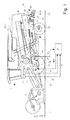
- FIG. 1 shows a side view of an agricultural machine designed as a combine harvester 1 during harvesting.
- the crop 2 is first picked up by a cutting unit 3, which feeds the crop 2 to an inclined conveyor 4, which is arranged on the front of the combine harvester 1.
- an inclined conveyor 4 transfers the crop 2 to a threshing mechanism 6 arranged in the machine housing 5 of the combine harvester 1.
- the threshing unit 6 processes the crop 2 intensively, so that the grains are released from the crops of the crop 2
- a grain consisting predominantly of grains Chaff mixture 7 is deposited on the threshing and separating basket 8 of the threshing 6 and passes through a preparation tray 9 to a known and therefore not further explained here cleaning device 10, in which the grains of the non-grain constituents, ie of straw and Spreader parts are separated.
- Overflowing over the cleaning device 10 consisting essentially of short straw and chaff screen overflow 11 passes through a Zunaturalgeber 12 in an even closer to described Strohzerklein ceremoniess- and Vertert sensory 15, which includes at least one below a Strohausfallhaube 14 arranged straw chopper 13 and a downstream distribution device 31.
- the separator 18 In the rear region of the threshing 6 is associated with a rotating counterclockwise turning drum 16, which assumes the emerging from the threshing 6, consisting essentially of threshed crops Gutstrom 17 and a separator 18 such as two juxtaposed separating rotors 19 feeds the goods 17
- the separator 18 In the rear region of the combine harvester 1 promote the still in the flow 17 grains 20 and possibly short straw 21 and chaff 22 are separated by falling through the screen openings provided with separation rotors 19 through a return bottom 23, the separator 18 is not on this Restricted execution, the separator 18 may also be designed as a known and therefore not shown Horden commonlyler, but it is also conceivable that the separator 18 is designed as a single rotor or double rotor system in which each rotor a so-called threshing un d deposition area has.
- the return bottom 23 transports grains 21, short straw 20 and chaff 22 also to the preparation tray 9 and via this likewise into the cleaning device 10, in which the grains 21 are separated from the short straw 20 and from the chaff 22
- the crop material 24 emerging from the separating rotors 19 at the end of the separating rotors 19 and for the most part consisting of straw is fed to the straw chopper 13 via the straw chute hood 14.
- the straw chopper 13 has a rotary cutter shaft 26 which is mounted in the chopper housing 27.
- the chopper shaft 26 is occupied with movable blades 28 which mesh with fixed in the chopper housing 27 counter knives 29.
- the crop 24 is shredded to shredded material 30 and accelerated and fed at high speed to a arranged on the machine housing 5 distribution device 31, with which the shredded material 30 is distributed on the field floor 32.
- the distributing device 31 are subordinate to later explained inventive guide elements 33, 34, with which the emerging from the distributor 31 shred 30 experiences in a manner to be described in more detail, at least in the vertical direction, a change in Gutaustrittraum.
- the combine harvester 1 is designed as a so-called slope combine harvester, the front axle 36 receives a known slope compensation system 37, wherein the two wheels 38 of the front axle 36 associated with such a leveling system 37
- Each slope compensation system 37 is substantially of a with the respective impeller 38 in Active connection standing wheel gear 39 is formed, soft about the front axle 36 is pivotally mounted on this.
- the pivoting of the wheel gear 39 is achieved in that between the brackets 40 of the front axle 36 and the wheel gears 39 each have a lifting cylinder 41 is arranged, the pressurization or pressure relief leads to a pivoting of the associated wheel gear 39 clockwise or counterclockwise about the front axle 36.
- the wheel gear 39 are pivoted in the manner described about the front axle 36, at the same time change the connected to the wheel gear 39 wheels 38 their position on the combine 1 in both the vertical and in the horizontal direction, whereby the machine housing 5 can be aligned.
- the combine harvester 1 shown has different sensors at different points in a manner to be described in more detail. These include first so-called tilt sensors 43, 44 which are fixedly connected to the machine housing 5. The tilt sensors 43, 44 detect the longitudinal and transverse inclination of the machine frame 5 and the field bottom 32 and generate depending on this longitudinal or transverse inclination signals H, l.
- the slope compensation systems 37 of the combine harvester 1 are further associated with rotational angle sensors 45, which determine the pivot angle 41 of the wheel gear 39 relative to the front axle 36 and thus the position of the wheels 38 to the machine housing 5.
- the rotation angle sensors 45 generate inclination signals K, L proportional to the position of the wheel gear 34 relative to the front axle 36
- the inclination sensors 43, 44 and the rotation angle sensors 45 are connected to a control and evaluation unit 47.
- the control and evaluation unit 47 determines control signals M, N as a function of the inclination signals H, l generated by the inclination sensors 43, 44 and depending on the inclination signals K, L generated by the rotation angle sensors 45.
- the control signals M, N control the pressurization or respectively Pressure relief of the lifting cylinder 41 of the slope compensation systems 37, each slope compensation system 37 is controlled separately, so that each impeller 38 can be adjusted individually to the bottom profile of the field bottom 32.
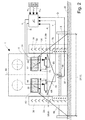
- FIG. 2 shows the rear view of the combine harvester 1 illustrated in FIG. 1 during harvesting on a horizontal field floor 32.
- the distributing device 31 consists of two side-by-side blowers 49, 50 arranged on the machine housing 5, behind which the shredded material 30 emerging on trajectories lies behind on a spreading width 51 the Dispose combine harvester 1 on the field floor 32, wherein the distribution width 51 in the illustrated embodiment advantageously corresponds to the working width 52 of the cutting unit 3 of the combine 1 and both the working width 51 and the distribution width 52 are arranged symmetrically to the central axis 53 of the combine 1, to simplify 2, only the outer trajectories 69, 70 of the shredded material 30 are shown.
- the trailing fans 49, 50 according to the invention guide elements 33, 34 are each arranged about an approximately perpendicular to the central axis 53 of the combine harvester 1 axis 54, 55 pivotally mounted on the machine housing 5, wherein between the machine housing 5 and an associated guide element 33, 34 rigidly arranged levers 56, 57 each have an actuator 58, 59 is articulated, with which the respective guide element 33, 34 can be pivoted.
- the actuators 58, 59 are designed as linear motors 60, 61 in the illustrated embodiment. However, it is also conceivable to perform the actuators 58, 59 as a hydraulic cylinder.
- the guide elements 33, 34 are arranged below the throwing fans 49, 50, so that the chopped material 30 emerging radially from the throwing blowers 49, 50 is not deflected by the guide elements 33, 44.
- the instantaneous positions of the guide elements 33, 34 are respectively detected via the linear motors 60, 61 associated displacement sensors 64, 65 proportional to the current displacement of the linear motors 61, 62 generate position signals P, R.
- the machine housing 5 is mounted in the rear area of the combine harvester 1 on a swinging rear axle 66 which adapts to the inclination of the field floor 32.
- the oscillating rear axle 66 of the combine harvester 1 is assigned a rotational angle sensor 67, which detects the instantaneous position of the rear axle 66 relative to the machine housing 5 and generates a tilt signal Q depending on the position.
- the oscillating rear axle 66 may also be associated with an inclination sensor, with which the inclination of the field bottom 32 can be determined.
- the displacement sensors 64, 65 on the linear motors 61, 62 and the rotation angle sensor 67 on the oscillating rear axle 66 are also connected to the control and evaluation unit 47 and pass to this the tilt signal Q generated by the rotation angle sensor 67 and those generated by the travel sensors 64, 65 Position signals P, R. While the tilt signals H generated by the tilt sensors 43, 44 fixed to the machine frame 5 are used to define the control signals M, N for the lift cylinders 41 of the slope compensation systems 37, the tilt signals K generated by the various rotation angle sensors 45, 67 are used , L, Q first to determine the deflection of the wheels 38 of the front axle 36 and the deflection of the oscillating mounted rear axle 66.
- tilt signals K, L, Q as described in more detail below, also used to generate control signals S, T, the a retraction or extension of the respective linear motors 60, 61 cause such d the guide plates 33, 34 according to the invention are pivoted in dependence on the inclination of the field bottom 32.
- the invention will now be described in detail.
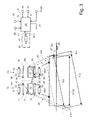
- the combine harvester 1 would be aligned almost horizontal to the ground 32, the throwing fans 49, 50 are also aligned horizontally because of their rigid articulation on the combine 1.
- the throwing fans 49, 50 have the distribution characteristic in a manner known per se that the shredded material 30 passing through the throwing fans 49, 50 is deposited on the floor 32 over a spreading width 51 which corresponds to the working width 52 of the cutting unit 3. If the combine harvester 1 now passes over a floor 32a which has a marked slope, the slope compensation system 37 already described would move the combine harvester 1 and the discharge fans 49, 50 connected to it again to a horizontal position.
- the distribution width 51a realized by the throwing blowers 49, 50 changes in such a way that the throwing distance shortens uphill while the throwing distance increases downhill. This is where the invention begins.
- the distribution width 51a and the working width 52a to end up in a similar range at least upstream of the hatch, the product flow 30 emerging from the throwing fans 49, 50 must be deflected more uphill.
- control and evaluation unit 47 would cause the adjustment of the actuators 75, 76 in such a way that the guide element 71, 72 respectively disposed downstream is pivoted about its pivot axis 77, 78 in the direction of the bottom 32a, so that the fury blower 49th As a result, this also means that in the downhill region the vertical width 51a and the working width 52a almost coincide,
- the control and evaluation unit 47 at least from the rotational angle sensor 67 associated with the oscillating rear axle 66 and / or the inclination signals K generated by the tilt compensation system 37 L, Q generates at least one control signal S. T.
- the adjustment of the guide elements 33, 34, 71, 72 by retraction or extension of the coupling rods of the actuators 58, 59, 75, 76, so that the guide elements 33, 34, 71, 72 about their jewellige pivot axis 54, 55, 77, 78 are pivoted, wherein the respective mountain side and bottom side guide element 33, 34 is pivoted about its pivot axis 54, 55 in the vertical direction upwards, while the valley side and top side guide element 71, 72 about its pivot axis 77, 78 in the vertical direction is swung down.
- the inclination sensors 43, 44 fixed to the machine housing 5 and the various rotation angle sensors 45, 67 are connected to the control and evaluation unit 47 and the control and evaluation unit 47 the inclination signals H generated by the inclination sensors 43, 44 l and the inclination signals K, L, Q generated by the rotation angle sensors 45, 67 and the control signals M, N of the lifting cylinders 41 of the slope compensation system 37 for defining the control signals S, T with which the linear motors 61, 62, 75, 76 are retracted and extended
- the control and evaluation unit 47 takes into account only a part of the signals described above.
- the guide elements 33, 34, 71, 72 are additionally adjusted in dependence on the wind direction and wind strength.
Landscapes
- Life Sciences & Earth Sciences (AREA)
- Environmental Sciences (AREA)
- Harvester Elements (AREA)
- Outside Dividers And Delivering Mechanisms For Harvesters (AREA)
- Threshing Machine Elements (AREA)
Abstract
Description
Die Erfindung betrifft eine Verteilvorrichtung zum Verteilen von aus einer Erntemaschine austretendem Erntegut nach dem Oberbegriff des Anspruchs 1,The invention relates to a distribution device for distributing crop material emerging from a harvester according to the preamble of
Eine Verteileinrichtung für aus einer Erntemaschine austretendes Häckselgut ist aus der
Nachteilig bei dieser Verteileinrichtung ist, dass sie nur bei Mähdreschern zweckmäßig einsetzbar ist, bei denen sich das Maschinengehäuse und/oder die Verteilvorrichtung bei der Erntefahrt am Hang zur Neigung des Feldes ausrichtet und die Verteileinrichtung somit einen gleichbleibenden Abstand zum Feldboden aufweist. Bei Hangmähdreschern, bei denen das Maschinengehäuse und/oder die Verteileinrichtung bei der Erntefahrt am Hang mit einer Hangausgleichseinrichtung zur Vertikalen ausgerichtet wird, weist die Verteileinrichtung hangaufwärts einen kürzeren Abstand und talseitig einen größeren Abstand zum Feldboden auf. Diese Abstände der Verteileinrichtung begrenzen die Wurfbahnen des Erntegutes. Eine Verstellung der Streubreite in Richtung Hang würde bewirken, dass die Erntegutmenge, die hangseitig schon vor dem Erreichen der gewünschten Streubreite auf den im Winkel zur Wurfbahn des Erntegutes verlaufenden Feldboden auftrifft, ansteigt.A disadvantage of this distribution device is that it can be used appropriately only in combine harvesters, in which the machine housing and / or the distribution device aligns at harvest time on a slope to the slope of the field and thus the distributor has a constant distance to the field soil. In Hangmähdreschern in which the machine housing and / or the distribution device is aligned with the crop ride on a slope with a slope compensation device to the vertical, the distributor has uphill a shorter distance and the valley side a greater distance from the field floor. These distances of the distribution device limit the trajectories of the crop. An adjustment of the spread in the direction of slope would cause the amount of crop, the slope before reaching the desired Spread on the impinging at an angle to the trajectory of the crop field soil hits, increases.
Der vorliegenden Erfindung liegt daher die Aufgabe zugrunde, die Nachteile des Standes der Technik zu vermeiden und insbesondere eine Vorrichtung anzugeben, bei der das Häckselgut unabhängig von der Hangneigung in gleichbleibender Verteilbreite auf dem Feld abgelegt wird.The present invention is therefore based on the object to avoid the disadvantages of the prior art and in particular to provide a device in which the shredded material is stored regardless of the slope in a constant distribution width in the field.
Diese Aufgabe wird erfindungsgemäß durch die kennzeichnenden Merkmale des Anspruchs 1 gelöst Weitere vorteilhafte Wirkungen des Erfindungsgegenstandes ergeben sich aus den Unteransprüchen.This object is achieved by the characterizing features of
Indem der Verteilvorrichtung wenigstens ein Leitelement nachgeordnet ist, mit dem die Gutbewegungsrichtung des aus der Verteilvorrichtung austretenden Erntegutes zumindest in vertikaler Richtung änderbar ist kann das Häckselgut unabhängig von der Hangneigung in gleichbleibender Verteilbreite auf dem Feldboden abgelegt werden.By the distribution device is arranged downstream of at least one guide element with which the Gutbewegungsrichtung of exiting the distributor crop is changeable at least in the vertical direction, the shredded material can be stored regardless of the slope in a constant distribution width on the field floor.
Dadurch, dass das Leitelement in Abhängigkeit von der Neigung des Feldbodens verstellbar ist, kann die Wurfbahn des Häckselgutes entsprechend der Hangneigung angepasst werden.Characterized in that the guide element is adjustable in dependence on the inclination of the field soil, the trajectory of the shredded material can be adjusted according to the slope.
Die Verstellbarkeit der Leitelemente ist in einer vorteilhaften Weiterbildung der Erfindung zudem so gestaltet, dass eine größere Wurfweite durch Einstellung einer höheren Wurfparabel für das Erntegutes realisiert wird.The adjustability of the guide elements is also designed in an advantageous development of the invention that a greater throwing distance is achieved by setting a higher throwing parabola for the crop.
Indem das jeweilige Leitelement in einer vorteilhaften Ausgestaltung das Leitelement flächig ausgebildet ist und in Gutabgaberichtung eine in vertikaler Richtung weisende Wölbung aufweist, kann die Gutumlenkung auf konstruktiv einfache Weise und dennoch präzise vorgenommen werden. Indem die Wölbung nur den äußeren Bereichen der Leitelemente angeformt ist, wird zudem Störungen im Gutfluss während des Passieren der Leitelemente entgegengewirkt.By the respective guide element in an advantageous embodiment, the guide element is formed flat and Gutabgaberichtung has a pointing in the vertical direction curvature, the Gutumlenkung can be made in a structurally simple manner and yet precise. By the curvature is formed only the outer regions of the vanes, also disturbances in the crop flow during passage of the vanes is counteracted.
Eine effiziente Anpassung der Verteilbreite hangaufwärts wird in vorteilhafter Ausgestaltung der Erfindung dann erreicht, wenn die Verteilvorrichtung ein oder mehrere Wurfgebläse umfasst und jedem Wurfgebläse zumindest im rückwärtigen untenseitigen Bereich ein Gutleitelement in der Weise zugeordnet ist, dass die Wölbung des jeweiligen Gutleitelementes in vertikaler Richtung aufwärts gerichtet ist. Analog hierzu wird eine effiziente Anpassung der Verteilbreite hangabwärts dann erreicht, wenn dem oder den Wurfgebläsen im rückwärtigen und obenseitigen Bereich weitere Gutleitelement in der Weise zugeordnet sind, dass die Wölbung des jeweiligen Gutleitelementes in vertikaler Richtung abwärts gerichtet ist.An efficient adjustment of the distribution width uphill is achieved in an advantageous embodiment of the invention, when the distributor comprises one or more impeller blower and each throw fan at least in the rear lower side area a Gutleitelement is assigned in such a way that the curvature of the respective Gutleitelementes directed vertically upward is. Analogous to this, an efficient adjustment of the distribution width down the slope is achieved when the or the blowers are assigned in the rear and top side area further Gutleitelement in such a way that the curvature of the respective Gutleitelementes is directed downwards in the vertical direction.
In vorteilhafter Ausgestaltung der Erfindung nimmt die Wölbung in Richtung der äußeren Bereiche der Leitelemente zu, sodass mit zunehmendem Einfluss der Neigung des Bodens auf die Verteilbreite auch die Intensität der Gutumlenkung zunimmt.In an advantageous embodiment of the invention, the curvature increases in the direction of the outer regions of the guide elements, so that with increasing influence of the inclination of the soil on the distribution width and the intensity of Gutumlenkung increases.
In einer vorteilhaften Ausgestaltung der Erfindung ist die Verteileinrichtung an einem Maschinengehäuse angeordnet ist, wobei das Maschinengehäuse mit einem Hangausgleichssystem gegenüber dem Feldboden ausrichtbar ist, so dass die mit dem Maschinengehäuse verbundenen Arbeitsorgane auch in hängigem Gelände eine annähernd horizontale Position einnehmen und damit auch bei der Erntefahrt am Hang optimale Ergebnisse erzielen,In an advantageous embodiment of the invention, the distribution device is arranged on a machine housing, wherein the machine housing is aligned with a slope compensation system relative to the field soil, so that the working bodies connected to the machine housing occupy an approximately horizontal position even in pending terrain and thus during harvesting get the best results on a slope
In vorteilhafter Ausgestaltung der Erfindung sind dem Maschinengehäuse ein oder mehrere Neigungssensoren zugeordnet und wobei die von den Neigungssensoren generierten Neigungssignale an eine Steuer- und Auswerteinheit übermittelt werden und die Steuer- und Auswerteinheit zumindest unter Berücksichtigung dieser Neigungssignale Steuersignale generiert, die eine Einstellung des Hangausgleichssystems in der Weise bewirken, dass zumindest das Maschinengehäuse in einer nahezu waagerechten Position gehalten wird, Im einfachsten Fall wird dies dadurch erreicht, dass die Einstellung des Hangausgleichssystems durch Druckbeaufschlagung oder Druckentlastung von dem Hangausgleichsystem zugeordneten Hubzylindern erfolgtIn an advantageous embodiment of the invention, one or more inclination sensors are assigned to the machine housing and wherein the inclination signals generated by the inclination signals are transmitted to a control and evaluation unit and the control and evaluation unit generates at least taking into account these inclination signals control signals indicating an adjustment of the slope compensation system in the Cause at least the machine housing is held in a nearly horizontal position, in the simplest case, this is achieved by the setting of the Slope compensation system by pressurization or pressure relief of the slope compensation system associated lifting cylinders takes place
In einer vorteilhaften Ausgestaltung der Erfindung ist es vorgesehen, dass die Stellung des zumindest einen Hangausgleichssystems gegenüber dem Maschinengehäuse mit einem Drehwinkelsensor erfasst wird, wobei der Drehwinkelsensor abhängig von der Stellung des Hangausgleichssystems zum Maschinengehäuse Neigungssignale generiert Auf diese Weise wird ein konstruktiv einfaches System zur Ermittlung der Hangneigung geschaffen.In an advantageous embodiment of the invention, it is provided that the position of the at least one slope compensation system relative to the machine housing is detected with a rotation angle sensor, the rotation angle sensor depending on the position of the slope compensation system to the machine housing generates tilt signals In this way, a structurally simple system for determining the Slope created.
In einer weiteren vorteilhaften Ausführung der Erfindung weist der Mähdrescher eine pendelnde Hinterachse auf und die Position der Hinterachse gegenüber dem Maschinengehäuse wird mit einem Drehwinkelsensor erfasst, wobei der Drehwinkelsensor abhängig von der Stellung des Hangausgleichssystems zum Maschinengehäuse Neigungssignale generiert, so dass auch über diese Drehwinkelsensoren auf einfache Weise die Neigung des Feldbodens ermittelt werden kann.In a further advantageous embodiment of the invention, the combine harvester on a swinging rear axle and the position of the rear axle relative to the machine housing is detected with a rotation angle sensor, wherein the rotation angle sensor depending on the position of the slope compensation system to the machine housing generates tilt signals, so that also easy on these rotation angle sensors Way the inclination of the field soil can be determined.
Indem die Steuer- und Auswerteeinheit zumindest aus dem der pendelnden Hinterachse zugeordneten Drehwinkelsensor und/oder dem dem Hangausgleichssystem zugeordneten Drehwinkelsensor generierten Neigungssignalen wenigstens ein Steuersignal zur Einstellung der Leitelemente generiert wird ein Regelungssystem geschaffen, welches sehr effizient die Verteilbreite an sich ändernde Hangneigungen anpassen kann,By generating the control and evaluation unit at least from the rotational angle sensor associated with the oscillating rear axle and / or inclination signals generated by the angle compensation system, at least one control signal for adjusting the guide elements, a control system is created which can very efficiently adapt the distribution width to changing slopes.
Eine sehr zuverlässig arbeitende Verstelleinrichtung ergibt sich dann, wenn in vorteilhafter Ausgestaltung jedem Leitelement ein Stellglied zur Verschwenkung des jeweiligen Leitelementes zugeordnet ist und wobei die in der Steuer- und Auswerteinheit generierten Steuersignale als Verstellwegsignale eine Verstellung des jeweiligen Stellgliedes bewirken,A very reliable adjusting device results when, in an advantageous embodiment, each control element is associated with an actuator for pivoting the respective guide element and wherein the control signals generated in the control and evaluation unit as Verstellwegsignale effect an adjustment of the respective actuator,
Eine effiziente Anpassung der Verteilbreite an die Arbeitsbreite wird sowohl hangaufwärts als auch hangabwärts dann erreicht, wenn das bergseitig und untenseitig angeordnete Leitelement um eine Schwenkachse in verlikaler Richtung nach oben verschwenk wird und das talseitig und obenseitig angeordnete Leitelement um eine Schwenkachse in vertikaler Richtung nach unten verschwenkt werden kann,An efficient adjustment of the spreading width to the working width is achieved both uphill and downhill when the uphill and downside arranged guide element is pivoted about a pivot axis in the vertical direction upward and the talc and upside arranged guide pivoted about a pivot axis in the vertical direction downwards can be,
indem die Lage des Leitelements über zumindest einen Wegesensor erfasst wird, der den aktuellen Verstellweg des jeweiligen Stellgliedes erfasst und an die Steuer- und Auswerteinheit übergibt, wobei in der Steuer- und Auswerteinheit solange eine Anpassung des Verstellweges vornimmt, bis der Verstellweg dem von der Steuer- und Auswerteinheit generierten Steuersignal entspricht, wird eine präzise Überwachung der Position des jeweiligen Leitelementes möglich.by detecting the position of the guide element via at least one displacement sensor, which detects the current displacement path of the respective actuator and transfers it to the control and evaluation, wherein in the control and evaluation unit as long as performs an adjustment of the adjustment until the adjustment of the control - And evaluation unit generated control signal corresponds, a precise monitoring of the position of the respective guide element is possible.
Weitere vorteilhafte Ausgestaltungen sind Gegenstand weiterer Unteransprüche und werden nachfolgend an Hand des in mehreren Figuren dargestellten Ausführungsbeispiels näher erläutert.Further advantageous embodiments are the subject of further subclaims and are explained in more detail below with reference to the embodiment shown in several figures.
Es zeigen.
- Fig.1
- eine schematische Seitenansicht eines Mähdreschers bei der Erntefahrt,
- Fig. 2
- eine Rückansicht der landwirtschaftlichen Arbeitsmaschine nach Fig. 1 bei der Erntefahrt in der horizontalen Ebene,
- Fig. 3
- eine Rückansicht der landwirtschaftlichen Arbeitsmaschine nach Fig. 1 bei der Erntefahrt am Hang.
- Fig.1
- a schematic side view of a combine harvester at harvest,
- Fig. 2
- a rear view of the agricultural machine of Figure 1 at the harvesting in the horizontal plane.
- Fig. 3
- a rear view of the agricultural machine of FIG. 1 at harvest on a slope.
Fig.1 zeigt eine Seitenansicht einer als Mähdrescher 1 ausgeführten landwirtschaftlichen Arbeitsmaschine bei der Erntefahrt. Das Erntegut 2 wird zunächst von einem Schneidwerk 3 aufgenommen, welches das Erntegut 2 einem Schrägförderer 4 zuführt, der frontseitig am Mähdrescher 1 angeordnet ist. Der Schragförderer 4 übergibt das Erntegut 2 an ein im Maschinengehäuse 5 des Mähdreschers 1 angeordnetes Dreschwerk 6, Das Dreschwerk 6 bearbeitet das Erntegut 2 intensiv, so dass die Körner aus den Früchten des Ernteguts 2 herausgelöst werden, Ein aus zum überwiegenden Teil aus Körnern bestehendes Korn-Spreu-Gemisch 7 wird an dem Dresch- und Abscheidekorb 8 des Dreschwerks 6 abgeschieden und gelangt über einen Vorbereitungsboden 9 zu einer an sich bekannten und daher hier nicht näher erläuterten Reinigungseinrichtung 10, in der die Körner von den Nichtkornbestandteilen, das heißt von Halm- und Spreuteilen getrennt werden. Der über die Reinigungseinrichtung 10 Überlaufende im wesentlichen aus Kurzstroh und Spreu bestehende Siebüberlauf 11 gelangt über einen Zuführboden 12 in eine noch näher zu beschreibende Strohzerkleinerungs- und Verterteinrichtung 15, die zumindest einen unterhalb einer Strohausfallhaube 14 angeordneten Strohhäcksler 13 sowie eine diesem nachgeordnete Verteileinrichtung 31 umfasst.1 shows a side view of an agricultural machine designed as a
Im rückwärtigen Bereich ist dem Dreschwerk 6 eine entgegen dem Uhrzeigersinn rotierende Wendetrommel 16 zugeordnet, die den aus dem Dreschwerk 6 austretenden, im wesentlichen aus ausgedroschenen Halmen bestehenden Gutstrom 17 annimmt und einer Trennvorrichtung 18 wie beispielsweise zwei nebeneinander angeordneten Trennrotoren 19 zuführt, die den Gutstrom 17 in den rückwärtigen Bereich des Mähdreschers 1 fördern Dabei werden die noch im Gutstrom 17 befindlichen Körner 20 sowie eventuell Kurzstroh 21 und Spreu 22 abgetrennt, indem sie durch die mit Sieböffnungen versehenen Trennrotoren 19 hindurch auf einen Rücklaufboden 23 fallen, Die Trennvorrichtung 18 ist nicht auf diese Ausführung beschränkt, so kann die Trenneinrichtung 18 auch als an sich bekannter und deshalb nicht dargestellter Hordenschüttler ausgeführt sein, Es ist aber auch denkbar, dass die Trenneinrichtung 18 als Einrotor- oder Doppelrotorsystem ausgebildet ist, bei dem jeder Rotor einen sogenannten Dresch- und Abscheidebereich aufweist.In the rear region of the threshing 6 is associated with a rotating counterclockwise turning
Der Rücklaufboden 23 transportiert Körner 21, Kurzstroh 20 und Spreu 22 ebenfalls zum Vorbereitungsboden 9 und über diesen ebenfalls in die Reinigungseinrichtung 10, in welcher die Körner 21 vom Kurzstroh 20 und von der Spreu 22 getrennt werden, Das am Ende der Trennrotoren 19 aus den Trennrotoren 19 austretende, zum größten Anteil aus Stroh bestehende Erntegut 24 wird über die Strohausfallhaube 14 dem Strohhäcksler 13 zugeführt. Der Strohhäcksler 13 weist eine rotierende Häckslerwelle 26 auf, die in dem Häckslergehäuse 27 gelagert ist. Die Häckslerwelle 26 ist mit beweglichen Messern 28 besetzt, die mit im Häckslergehäuse 27 fest angeordneten Gegenmessern 29 kämmen. Mit diesen Messern 28, 29 wird das Erntegut 24 zu Häckselgut 30 zerkleinert und beschleunigt und mit hoher Geschwindigkeit einer an dem Maschinengehäuse 5 angeordneten Verteilvorrichtung 31 zugeführt, mit der das Häckselgut 30 auf dem Feldboden 32 verteilt wird. Der Verteilvorrichtung 31 sind an späterer Stelle näher erläuterte erfindungsgemäße Leitelemente 33, 34 nachgeordnet, mit denen das aus der Verteileinrichtung 31 austretende Häckselgut 30 in noch näher zu beschreibender Weise zumindest in vertikaler Richtung eine Änderung der Gutaustrittrichtung erfährt.The
Im dargestellten Ausführungsbeispiel ist der Mähdrescher 1 als sogenannter Hangmähdrescher ausgeführt, dessen Vorderachse 36 ein an sich bekanntes Hangausgleichssystem 37 aufnimmt, wobei beiden Laufrädern 38 der Vorderachse 36 ein solches Hangausgleichssystem 37 zugeordnet ist Jedes Hangausgleichsystem 37 wird im wesentlichen von einem mit dem jeweiligen Laufrad 38 in Wirkverbindung stehendem Radgetriebe 39 gebildet, weiches um die Vorderachse 36 verschwenkbar an dieser angeordnet ist. Die Verschwenkbarkeit der Radgetriebe 39 wird dadurch erreicht, dass zwischen den Konsolen 40 der Vorderachse 36 und den Radgetrieben 39 jeweils ein Hubzylinder 41 angeordnet ist, dessen Druckbeaufschlagung oder Druckentlastung zu einem Verschwenken des zugehörigen Radgetriebes 39 im oder entgegen dem Uhrzeigersinn um die Vorderachse 36 führt. Indem die Radgetriebe 39 in der beschriebenen Weise um die Vorderachse 36 verschwenkt werden, ändern zugleich die mit den Radgetrieben 39 verbundenen Laufräder 38 ihre Position am Mähdrescher 1 sowohl in vertikaler als auch in horizontaler Richtung, wodurch das Maschinengehäuse 5 ausgerichtet werden kann.In the illustrated embodiment, the
Der dargestellte Mähdrescher 1 weist an verschiedenen Stellen in noch näher zu beschreibende Weise unterschiedliche Sensoren auf. Hierzu gehören zunächst sogenannte Neigungssensoren 43, 44, die fest mit dem Maschinengehäuse 5 verbunden sind. Die Neigungssensoren 43, 44 erfassen die Längs- und Querneigung des Maschinengestells 5 beziehungsweise des Feldbodens 32 und generieren abhängig von dieser Längs- beziehungsweise Querneigung Neigungssignale H,l.The
Den Hangausgleichssystemen 37 des Mähdreschers 1 sind weiterhin Drehwinkelsensoren 45 zugeordnet, die die Verschwenkwinkel 41 der Radgetriebe 39 gegenüber der Vorderachse 36 und damit die Lage der Laufräder 38 zum Maschinengehäuse 5 ermitteln. Die Drehwinkelsensoren 45 generieren proportional zur Lage der Radgetriebe 34 zur Vorderachse 36 Neigungssignale K, LThe
Die Neigungssensoren 43, 44 und die Drehwinkelsensoren 45 sind mit einer Steuer- und Auswerteinheit 47 verbunden. Die Steuer- und Auswerteinheit 47 ermittelt in Abhängigkeit von den von den Neigungssensoren 43, 44 generierten Neigungssignalen H, l und in Abhängigkeit von den von den Drehwinkelsensoren 45 generierten Neigungssignalen K, L Steuersignale M, N, Die Steuersignal M, N regeln die Druckbeaufschlagung beziehungsweise Druckentlastung der Hubzylinder 41 der Hangausgleichssysteme 37, wobei jedes Hangausgleichssystem 37 getrennt angesteuert wird, so dass jedes Laufrad 38 individuell an das Bodenprofil des Feldbodens 32 angepasst werden kann. Auf diese Weise ist es möglich die exakte Längs" und Querneigung des Maschinengehäuses 5 sowie die genaue Position der Laufräder 38 zu ermitteln und diese so zu verändern, dass das Maschinengestell 5 und die damit verbundenen Arbeitsorgane 10, 18 eine annähernd horizontale Position einnehmen, damit diese auch in hängigem Gelände optimale Ergebnisse erzielen.The
Fig. 2 zeigt die Rückansicht des in Fig.1 dargestellten Mähdrescher 1 bei der Erntefahrt auf horizontalem Feldboden 32, Die Verteileinrichtung 31 besteht aus zwei nebeneinander am Maschinengehäuse 5 angeordneten Wurfgebläsen 49, 50, die das auf Wurfbahnen austretende Häckselgut 30 auf einer Verteilbreite 51 hinter dem Mähdrescher 1 auf dem Feldboden 32 verteilen, wobei die Verteilbreite 51 im dargestellten Ausführungsbeispiel vorteilhafterweise der Arbeitsbreite 52 des Schneidwerks 3 des Mähdreschers 1 entspricht und sowohl die Arbeitsbreite 51 als auch die Verteilbreite 52 symmetrisch zur Mittelachse 53 des Mähdreschers 1 angeordnet sind, Zur Vereinfachung sind in Fig. 2 nur die äußeren Wurfbahnen 69, 70 des Häckselgutes 30 dargestellt Die den Wurfgebläsen 49, 50 nachgeordneten erfindungsgemäßen Leitelemente 33, 34 sind jeweils um eine annähernd senkrecht zur Mittelachse 53 des Mähdreschers 1 verlaufende Achse 54, 55 verschwenkbar an dem Maschinengehäuse 5 angeordnet, wobei zwischen dem Maschinengehäuse 5 und einem am zugehörigen Leitelement 33, 34 starr angeordneten Hebel 56, 57 jeweils ein Stellglied 58, 59 angelenkt ist, mit dem das jeweilige Leitelement 33, 34 verschwenkt werden kann. Die Stellglieder 58, 59 sind im dargestellten Ausführungsbeispiel als Linearmotoren 60, 61 ausgeführt. Es ist jedoch auch denkbar, die Stellglieder 58, 59 als Hydraulikzylinder auszuführen. Die Leitelemente 33, 34 sind unterhalb der Wurfgebläse 49, 50 angeordnet, so dass das radial aus den Wurfgebläsen 49, 50 austretende Häckselgut 30 nicht durch die Leitelemente 33, 44 umgelenkt wird.FIG. 2 shows the rear view of the
Die momentanen Positionen der Leitelemente 33, 34 werden jeweils über den Lineamotoren 60, 61 zugeordnete Wegesensoren 64, 65 erfasst die proportional zum aktuellen Verstellweg der Linearmotoren 61, 62 Positionssignale P, R generieren.The instantaneous positions of the
Das Maschinengehäuse 5 ist im hinteren Bereich des Mähdreschers 1 auf einer pendelnden Hinterachse 66 gelagert, die sich an die Neigung des Feldbodens 32 anpasst. Der pendelnden Hinterachse 66 des Mähdreschers 1 ist ein Drehwinkelsensor 67 zugeordnet, der die momentane Lage der Hinterachse 66 zum Maschinengehäuse 5 erfasst und lageabhängig ein Neigungssignal Q generiert. Alternativ kann der pendelnden Hinterachse 66 auch ein Neigungssensor zugeordnet sein, mit dem die Neigung des Feldbodens 32 ermittelbar ist.The
Die Wegesensoren 64, 65 an den Linearmotoren 61, 62 und der Drehwinkelsensor 67 an der pendelnden Hinterachse 66 sind ebenfalls mit der Steuer und Auswerteeinheit 47 verbunden und übergeben an diese das von dem Drehwinkelsensor 67 erzeugte Neigungssignal Q und die von den Wegesensoren 64, 65 erzeugten Positionssignale P, R. Während die von den am Maschinengestell 5 fixierten Neigungssensoren 43, 44 generierten Neigungssignale H, zur Definition von Steuersignalen M, N für die Hubzylinder 41 der Hangausgleichssysteme 37 herangezogen werden, dienen die von den verschiedenen Drehwinkelsensoren 45, 67 generierten Neigungssignale K,L,Q zunächst zur Ermittlung der Auslenkung der Laufräder 38 der Vorderachse 36 sowie der Auslenkung der pendelnd gelagerten Hinterachse 66. Zugleich werden diese Neigungssignale K,L,Q, wie nachfolgen näher beschrieben, auch zur Generierung von Steuersignalen S, T herangezogen, die ein Ein- oder Ausfahren der jeweiligen Linearmotoren 60, 61 derart bewirken, dass die erfindungsgemäßen Leitbleche 33, 34 in Abhängigkeit von der Neigung des Feldbodens 32 verschwenkt werden.The
In der schematischen Darstellung nach Fig. 3 wird nun die Erfindung im Detail beschrieben. In ebenem Gelände würde der Mähdrescher 1 nahezu horizontal zum Boden 32 ausgerichtet sein, wobei die Wurfgebläse 49, 50 wegen ihrer starren Anlenkung am Mähdrescher 1 ebenfalls horizontal ausgerichtet sind. In diesem Fall haben die Wurfgebläse 49, 50 in an sich bekannter Weise die Verteileigenschaft, dass das die Wurfgebläse 49, 50 durchlaufende Häckselgut 30 über eine Verteilbreite 51 auf dem Boden 32 abgelegt wird, die der Arbeitsbreite 52 des Schneidwerks 3 entspricht. Überfährt der Mähdrescher 1 nun einen Boden 32a, der eine deutliche Hangneigung aufweist, würde das bereits beschriebene Hangausgleichssystem 37 den Mähdrescher 1 und die mit ihm fest verbundenen Wurfgebläse 49, 50 wieder in eine horizontale Position bewegen. Dabei ändert sich die von den Wurfgebläsen 49, 50 realisierte Verteilbreite 51a in der Weise, dass sich die Wurfweite hangaufwärts verkürzt, während die Wurfweite hangabwärts zunimmt. Hier setzt nun die Erfindung an. Damit zumindest hatigaufwärts die Verteilbreite 51a und die Arbeitsbreite 52a in einem ähnlichen Bereich enden, muss der aus den Wurfgebläsen 49, 50 austretende Gutstrom 30 stärker bergauf ausgelenkt werden.In the schematic representation of Fig. 3, the invention will now be described in detail. In flat terrain, the
Dies geschieht in erfindungsgemäßer Weise dadurch, dass zumindest das hangaufwärts angeordnete Leitelement 34 proportional zur Hangneigung ausgelenkt wird, sodass sich zumindest hangaufwärts wieder die ursprüngliche Verteilbreite 51 einstellt. Wie bereits beschrieben wird dies im einfachsten Fall dadurch erreicht, dass das hangaufwärts gelegene Leitelement 34 durch Verstellung des ihm zugeordneten Stellgliedes 59 um seine Schwenkachse 55 in vertikaler Richtung ausgelenkt wird, wobei die Auslenkung ϕ durch die Steuer- und Auswerteinheit 47 so in Abhängigkeit von der Verschwenkung des Maschinengehäuses 5 bestimmt wird, dass zumindest hangaufwärts die Verteilbreite 51a wieder mit der Arbeitsbreite 52a zusammenfällt. In analoger Weise wird die Verstellung des weiteren Leitelementes 33 vorgenommen, wenn der Mähdrescher 1 in umgekehrter Richtung den Boden 32 überquert sodass das in Figur 3 hangabwärts weisende Leitelement 33 dann hangaufwärts angeordnet ist.This is done according to the invention in that at least the
Aus Figur 3 ist zudem ersichtlich, dass sich bei geneigtem Boden 32a hangabwärts eine größere Wurfweite einstellt, sodass die Verteilbreite 51a des Erntegutes 30 hangabwärts über die Arbeitsbreite 52a hinausgehen würde Dies kann in vorteilhafter Ausgestaltung der Erfindung dadurch vermieden werden, dass den Wurfgebläsen 49, 50 zudem obenseitig weitere Leitelemente 71, 72 und zugehörige Verstellmechanismen 73, 74 zugeordnet sein können, die im einfachsten Fall spiegelbildlich zu den bereits beschriebenen Leitelementen 33, 34 und ihren Stellgliedern 58, 59 ausgeführt und angesteuert sind. Für diesen Fall würde die Steuer- und Auswerteinheit 47 die Verstellung der Stellglieder 75, 76 in der Weise bewirken, dass das jeweils hangabwärts angeordnete Leitelement 71, 72 um seine Schwenkachse 77, 78 in Richtung Boden 32a verschwenkt wird, sodass das aus den Wutlgebläsen 49, 50 austretende Erntegut 30 in Richtung Boden 32 umgelenkt wird, Im Ergebnis führt dies dazu, dass auch in dem hangabwärts liegenden Bereich die Vertelbreite 51a und die Arbeitsbreite 52a nahezu zusammenfallen,It can also be seen from FIG. 3 that a greater range of throwing occurs on
Der Effekt der Gutumlenkung wird auch dadurch noch erhöht, dass die Leitelemente 33, 34, 71, 72 gemäß der Detailansicht nach Fig. 4 gutabgabeseitig gewölbt ausgeführt sind, wobei bei den untenseitig den Wurfgebläsen 49, 50 zugeordneten Leitelemente 33, 34 die Wölbung 79 vertikal nach oben gerichtet ist während sie bei den oberhalb der Wurfgebläse 49, 50 angeordneten Leitelementen 71, 72 vertikal nach unten weist. In einer vorteilhaften Ausgestaltung sind den Gutleitelementen 33, 34, 71, 72 die Wölbungen 79 nur in ihren gutabgabeseitigen Randbereichen angeformt. Indem die Wölbung in Richtung der Randbereiche zudem wird sichergestellt, dass mit zunehmendem Einfluss der Neigung des Bodens 32a auf die Verteilbreite 51 die Intensität der Gutumlenkung ebenfalls steigt, sodass auch bei Hangneigung eine optimale Verteilbreite 51a erreicht wird.The effect of Gutumlenkung is also increased by the fact that the
Zur Realisierung einer hochpräzisen Verstellung der verschiedenen Leitelemente 33, 34, 71, 72 ist es vorgesehen, dass die Steuer- und Auswerteeinheit 47 zumindest aus dem der pendelnden Hinterachse 66 zugeordneten Drehwinkelsensor 67 und/oder dem dem Hangausgleichssystem 37 zugeordneten Drehwinkelsensor 45 generierten Neigungssignalen K,L,Q wenigstens ein Steuersignal S. T generiert. Weiter ist, wie bereits beschrieben, jedem Leitelement 33, 34, 72, 73 ein Stellglied 58, 59, 75, 76 zur Verschwenkung des jeweiligen Leitelementes 33, 34, 72, 73 zugeordnet, wobei die in der Steuer- und Auswerteinheit 47 generierten Steuersignale S, T als Verstellwegsignale eine Verstellung des jeweiligen Stellgliedes 58, 59, 75, 76 bewirken. Im einfachsten Fall erfolgt die Verstellung der Leitelemente 33, 34, 71, 72 durch Ein- oder Ausfahren der Koppelstangen der Stellglieder 58, 59, 75, 76, sodass die Leitelemente 33, 34, 71, 72 um ihre jewellige Schwenkachse 54, 55, 77, 78 verschwenkt werden, wobei das jeweils bergseitig und untenseitig angeordnete Leitelement 33, 34 um seine Schwenkachse 54, 55 in vertikaler Richtung nach oben verschwenk wird, während das talseitig und obenseitig angeordnete Leitelement 71, 72 um seine Schwenkachse 77, 78 in vertikaler Richtung nach unten verschwenk wird.In order to realize a high-precision adjustment of the
Es liegt im Rahmen der Erfindung, dass die am Maschinengehäuse 5 fixierten Neigungssensoren 43, 44 und die verschiedenen Drehwinkelsensoren 45, 67 mit der Steuer und Auswerteeinheit 47 verbunden sind und die Steuer- und Auswerteeinheit 47 die von den Neigungssensoren 43, 44 generierten Neigungssignale H, l und die von den Drehwinkelsensoren 45, 67 generierten Neigungssignale K,L,Q sowie die Steuersignale M, N der Hubzylinder 41 des Hangausgleichssystems 37 zur Definition der Steuersignale S, T heranzieht, mit der die Linearmotoren 61, 62, 75, 76 ein- und ausgefahren werden, Es liegt zudem im Rahmen der Erfindung, dass die Steuer- und Auswerteinheit 47 nur einen Teil der zuvor beschriebenen Signale berücksichtigt.It is within the scope of the invention that the
Ferner wird die Lage aller Leitelemente 33, 34, 71, 72 über Wegesensoren 64, 65 erfasst, die den aktuellen Verstellweg des jeweiligen Stellgliedes 58, 59, 75, 76 erfasst und an die Steuer- und Auswerteinheit 47 übergibt, wobei die Steuer- und Auswerteinheit 47 solange eine Anpassung des Verstellweges vornimmt, bis der Verstellweg dem von der Steuer- und Auswerteinheit 47 generierten Steuersignal S, T entspricht.Furthermore, the position of all the
Zudem liegt es im Rahmen der Erfindung, dass die Leitelemente 33, 34, 71, 72 zusätzlich in Abhängigkeit von der Windrichtung und Windstärke verstellt werden.In addition, it is within the scope of the invention that the
Es liegt im Rahmen des Könnens eines Fachmannes die beschriebenen Ausführungsbeispiele in nicht dargestellter Weise abzuwandeln oder in anderen Maschinensystemen einzusetzen, um die beschriebenen Effekte zu erzielen, ohne dabei den Rahmen der Erfindung zu verlassen,It is within the skill of one skilled in the art to modify the described embodiments in a manner not shown or to use in other machine systems to achieve the effects described, without departing from the scope of the invention,
- 11
- MähdrescherHarvester
- 22
- Erntegutcrop
- 33
- Schneidwerkcutting
- 44
- Schrägfördererfeederhouse
- 55
- Maschinengehäusemachine housing
- 66
- Dreschwerkthreshing
- 77
- Korn-Spreu-GemischGrain chaff mixture
- 88th
- Abscheidekorbseparator concave
- 99
- Vorbereitungsbodenpreparing the ground
- 1010
- Reinigungseinrichtungcleaning device
- 1111
- Siebüberlaufscreen oversize
- 1212
- Zuführbodenfeed pan
- 1313
- Strohhäckslerstraw chopper
- 1414
- StrohausfallhaubeRear hood
- 1515
- Strohzerkleinerungs- und -verteileinrichtungStraw crushing and distribution device
- 1616
- Wendetrommelbeater
- 1717
- Gutstrommaterial flow
- 1818
- Trennvorrichtungseparating device
- 1919
- Trennrotorseparating rotor
- 2020
- Kurzstrohshort straw
- 2121
- Körnergrains
- 2222
- Spreuchaff
- 2323
- RücklaufbodenReturn pan
- 2424
- Erntegutcrop
- 2525
- 2626
- HäckslerwelleHäckslerwelle
- 2727
- Häckslergehäusechopper housing
- 2828
- bewegliche Messermovable knives
- 2929
- Gegenmesseragainst knife
- 3030
- Häckselgutchaff
- 3131
- Verteileinrichtungdistributor
- 3232
- Feldbodenfield soil
- 3333
- Leitelementvane
- 3434
- Leitelementvane
- 3535
- 3636
- VorderachseFront
- 3737
- HangausgleichssystemLeveling System
- 3838
- LaufradWheel
- 3939
- Radgetriebewheel gear
- 4040
- Konsoleconsole
- 4141
- Hubzylinderlifting cylinder
- 4242
- 4343
- Neigungssensortilt sensor
- 4444
- Neigungssensortilt sensor
- 4545
- DrehwinkelsensorRotation angle sensor
- 4747
- Steuer- und AuswerteeinheitControl and evaluation unit
- 4848
- 4949
- Wurfgebläseimpeller blower
- 5050
- Wurfgebläseimpeller blower
- 5151
- Verteilbreitespreading width
- 5252
- Arbeitsbreiteworking width
- 5353
- Mittelachsecentral axis
- 5454
- Achseaxis
- 5555
- Achseaxis
- 5656
- Hebellever
- 5757
- Hebellever
- 5858
- Stellgliedactuator
- 5959
- Stellgliedactuator
- 6060
- Linearmotorlinear motor
- 6161
- Linearmotorlinear motor
- 6262
- 6363
- 6464
- Wegesensortravel sensor
- 6565
- Wegesensortravel sensor
- 6666
- pendelnde Hinterachseswinging rear axle
- 6767
- DrehwinkelsensorRotation angle sensor
- 6868
- 6969
- Wurfbahntrajectory
- 7070
- Wurfbahntrajectory
- 7171
- Leitelementvane
- 7272
- Leitelementvane
- 7373
- Verstellmechanismusadjustment
- 7474
- Verstellmechanismusadjustment
- 7575
- Stellgliedactuator
- 7676
- Stellgliedactuator
- 7777
- Schwenkachseswivel axis
- 7878
- Schwenkachseswivel axis
- 7979
- Wölbungbulge
- HH
- Neigungssignaltilt signal
- II
- Neigungssignaltilt signal
- KK
- Neigungssignaltilt signal
- LL
- Neigungssignaltilt signal
- MM
- Steuersignalcontrol signal
- NN
- Steuersignalcontrol signal
- PP
- Positionssignalposition signal
- Neigungssignaltilt signal
- RR
- Positionssignalposition signal
- SS
- Steuersignalcontrol signal
- TT
- Steuersignalcontrol signal
Claims (18)
dadurch gekennzeichnet,
dass der Verteilvorrichtung (31) wenigstens ein Leitelement (33, 34, 72, 73) nachgeordnet ist, mit dem die Gutbewegungsrichtung des aus der Verteilvorrichtung (31) austretenden Erntegutes (30) zumindest in vertikaler Richtung änderbar ist.Distributor (31) for distributing a crop (30) leaving a combine harvester (1) on the field floor (32),
characterized,
that the distribution device (31) comprises at least one guide element (33, 34, 72, 73) is arranged downstream, with which the Gutbewegungsrichtung emerging from the distributor device (31) the crop material (30) is changed at least in the vertical direction.
dadurch gekennzeichnet,
dass das Leitelement (33, 34, 72, 73) in Abhängigkeit von der Neigung des Feldbodens (32) verstellbar ist.Distributor according to claim 1,
characterized,
in that the guide element (33, 34, 72, 73) is adjustable as a function of the inclination of the field bottom (32).
dadurch gekennzeichnet.
dass die Vetstellbarkeit der Leitelemente (33, 34, 72, 73) eine größere Wurfweite durch Einstellung einer höheren Wurfparabel für das Erntegutes (30) bewirkt.Distributor according to one of the preceding claims,
characterized.
that the Vetstellbarkeit the guide elements (33, 34, 72, 73) causes a greater throw by setting a higher parameet for the crop (30).
dadurch gekennzeichnet,
dass das Leitelement (33, 34, 72, 73) flächig ausgebildet ist und in Gutabgaberichtung eine in vertikaler Richtung weisende Wölbung (79) aufweist,Distributor according to one of the preceding claims,
characterized,
that the guide element (33, 34, 72, 73) is flat and formed in a Gutabgaberichtung pointing in the vertical direction curvature (79)
dadurch gekennzeichnet,
dass die Wölbung (79) nur den äußeren Bereichen der Leitelemente (33, 34, 72, 73) angeformt ist.Distributor according to claim 4,
characterized,
that the curvature (79) is formed only on the outer regions of the guide elements (33, 34, 72, 73).
dadurch gekennzeichnet.
dass die Wölbung (79) in Richtung der äußeren Bereiche der Leitelemente (33, 34, 72, 73) zunimmt.Distributor according to claim 5,
characterized.
in that the curvature (79) increases in the direction of the outer regions of the guide elements (33, 34, 72, 73).
dadurch gekennzeichnet,
dass die Verteilvorrichtung (31) ein oder mehrere Wurfgebläse (49, 50) umfasst und jedem Wurfgebläse (49, 50) zumindest im rückwärtigen untenseitigen Bereich ein Gutleitelement (33, 34) in der Weise zugeordnet ist, dass die Wölbung (79) des jeweiligen Gutlestelementes (33, 34) in vertikaler Richtung aufwärts gerichtet ist.Distributor according to one of the preceding claims,
characterized,
that the distribution device (31) and one or more impeller blower (49, 50) each casting blower (49, 50) at least in the rear bottom-side region of a Gutleitelement (33, 34) is associated in such a way that the curvature (79) of the respective Gutlestelementes (33, 34) is directed upward in the vertical direction.
dadurch gekennzeichnet,
dass dem oder den Wurfgebläsen (49, 50) im rückwärtigen und obenseitigen Bereich weitere Gutleitelement (72, 73) in der Weise zugeordnet sind, dass die Wölbung (79) des jeweiligen Gutleitelementes (72, 73) in vertikaler Richtung abwärts gerichtet ist.Distributor according to claim 7,
characterized,
in that in the rear and top area further material-guiding elements (72, 73) are assigned to the one or more throwing fans (49, 50) in such a way that the curvature (79) of the respective goods-conveying element (72, 73) is directed downwards in the vertical direction.
dadurch gekennzeichnet,
dass die Verteileinrichtung (31) an einem Maschinengehäuse (5) angeordnet ist, wobei das Maschinengehäuse (5) mit einem Hangausgleichssystem (37) gegenüber dem Feldboden (32) ausrichtbar ist.Distributor according to one of the preceding claims,
characterized,
that the distribution device (31) to a machine housing (5) is arranged, wherein the machine housing (5) is aligned with a slope compensation system (37) relative to the box bottom (32).
dadurch gekennzeichnet,
dass dem Maschinengehäuse (5) ein oder mehrere Neigungssensoren (43, 44) zugeordnet sind und wobei die von den Neigungssensoren (43, 44) generierten Neigungssignale (H, I) an eine Steuer- und Auswerteinheit (47) übermittelt werden und die Steuer- und Auswerteinheit (47) zumindest unter Berücksichtigung dieser Neigungssignale (H, I) Steuersignale (M, N) generiert, die eine Einstellung des Hangausgleichssystems (37) in der Weise bewirken, dass zumindest das Maschinengehäuse (5) in einer nahezu waagerechten Position gehalten wird,Distributor according to claim 9,
characterized,
in that one or more inclination sensors (43, 44) are assigned to the machine housing (5) and that the inclination signals (H, I) generated by the inclination sensors (43, 44) are transmitted to a control and evaluation unit (47) and the control unit and evaluation unit (47) at least taking into account these inclination signals (H, I) generated control signals (M, N), which cause an adjustment of the slope compensation system (37) in the manner that at least the machine housing (5) is held in a nearly horizontal position,
dadurch gekennzeichnet,
dass die Einstellung des Hangausgleichssystems (37) durch Druckbeaufschlagung oder Druckentlastung von dem Hangausgleichsystem (37) zugeordneten Hubzylindern (41) erfolgtDistributor according to claim 10.
characterized,
that the adjustment of the slope compensation system (37) is carried out by pressurization or depressurization of the slope compensation system (37) associated with lifting cylinders (41)
dadurch gekennzeichnet,
dass die Stellung des zumindest einen Hangausgleichssystems (37) gegenüber dem Maschinengehäuse (5) mit einem Drehwinkelsensor (45) erfasst wird, wobei der Drehwinkelsensor (45) abhängig von der Stellung des Hangausgleichssystems (37) zum Maschinengehäuse (5) Neigungssignale (K, L) generiert.Distributor according to one of the preceding claims,
characterized,
in that the position of the at least one slope compensation system (37) relative to the machine housing (5) is detected by a rotation angle sensor (45), the rotation angle sensor (45) depending on the position of the slope compensation system (37) to the machine housing (5) inclination signals (K, L ) generated.
dadurch gekennzeichnet
dass der Mähdrescher (1) eine pendelnde Hinterachse (66) aufweist und die Position der Hinterachse (66) gegenüber dem Maschinengehäuse (5) mit einem Drehwinkelsensor (67) erfasst wird, wobei der Drehwinkelsensor (45) abhängig von der Stellung des Hangausgleichssystems (37) zum Maschinengehäuse (5) Neigungssignale (Q) generiert.Distributor according to one of the preceding claims,
characterized
in that the combine harvester (1) has a pendulum rear axle (66) and the position of the rear axle (66) relative to the machine housing (5) is detected by a rotation angle sensor (67), the rotation angle sensor (45) being dependent on the position of the slope compensation system (37 ) to the machine housing (5) inclination signals (Q) generated.
dadurch gekennzeichnet,
dass die Steuer- und Auswerteeinheit (47) zumindest aus dem der pendelnden Hinterachse (66) zugeordneten Drehwinkelsensor (67) und/oder dem dem Hangausgleichssystem (37) zugeordneten Drehwinkelsensor, (45) generierten Neigungssignalen (K,L,Q) wenigstens ein Steuersignal (S, T) zur Einstellung der Leitelemente (33, 34, 71 ,72) generiertDistributor according to one of the preceding claims,
characterized,
in that the control and evaluation unit (47) generates at least one control signal from the rotational angle sensor (67) associated with the oscillating rear axle (66) and / or the rotational angle sensor (45) associated with the tilt compensation system (37) (S, T) for setting the guide elements (33, 34, 71, 72) generated
dadurch gekennzeichnet,
dass jedem Leitelement (33, 34, 71, 72) ein Stellglied (58, 59, 75, 76) zur Verschwenkung des jeweiligen Leitelementes (33, 34, 71, 72) zugeordnet ist und wobei die in der Steuer- und Auswerteinheit (47) generierten Steuersignale (S, T) als Verstelwegsignale eine Verstellung des jeweiligen Stellgliedes (58, 59, 75, 76) bewirken.Distributor according to one of the preceding claims,
characterized,
in that each guide element (33, 34, 71, 72) is associated with an actuator (58, 59, 75, 76) for pivoting the respective guide element (33, 34, 71, 72), and wherein the control unit and the evaluation unit (47 ) generate control signals (S, T) as Verstelwegsignale an adjustment of the respective actuator (58, 59, 75, 76).
dadurch gekennzeichnet,
dass das bergseitig und untenseitig angeordnete Leitelement (33) um eine Schwenkachse (55) in vertikaler Richtung nach oben verschwenk wird,Distributor according to claim 15,
characterized,
that the mountain side and the lower side arranged guide element (33) about a pivot axis (55) which can pivot in a vertical upward direction,
dadurch gekennzeichnet,
dass das talseitig und obenseitig angeordnete Leitelement (71) um eine Schwenkachse (77) in vertikaler Richtung nach unten verschwenk wird.Distributor according to claim 15,
characterized,
that the valley side and above each other arranged conducting element (71) about a pivot axis (77) which can pivot in the vertical direction downwards.
dadurch gekennzeichnet,
dass die Lage des Leitelements (33, 34, 71, 72) über zumindest einen Wegesensor (64, 65) erfasst wird, der den aktuellen Verstellweg des jeweiligen Stellgliedes (58, 59) erfasst und an die Steuer- und Auswerteinheit (47) übergibt, wobei in der Steuer- und Auswerteinheit (47) solange eine Anpassung des Verstellweges vornimmt, bis der Verstellweg dem von der Steuer- und Auswerteinheit (47) generierten Steuersignal (S, T) entsprichtDistributor according to one of the preceding claims,
characterized,
that the position of the guide element (33, 34, 71, 72) via at least one path sensor (64, 65) is detected, the passes the current adjustment of the respective actuator (58, 59) and transmitted to the control and evaluation unit (47) , wherein in the control and evaluation unit (47) as long as an adjustment of the adjustment makes until the adjustment corresponds to the control and evaluation unit (47) generated control signal (S, T)
Applications Claiming Priority (1)
| Application Number | Priority Date | Filing Date | Title |
|---|---|---|---|
| DE200610026041 DE102006026041A1 (en) | 2006-06-01 | 2006-06-01 | Distributor for distributing crop material exiting a harvester |
Publications (3)
| Publication Number | Publication Date |
|---|---|
| EP1862055A2 true EP1862055A2 (en) | 2007-12-05 |
| EP1862055A3 EP1862055A3 (en) | 2008-09-03 |
| EP1862055B1 EP1862055B1 (en) | 2017-05-10 |
Family
ID=38474065
Family Applications (1)
| Application Number | Title | Priority Date | Filing Date |
|---|---|---|---|
| EP07103435.9A Active EP1862055B1 (en) | 2006-06-01 | 2007-03-02 | Distribution device for distributing crops being discharged from a harvester |
Country Status (2)
| Country | Link |
|---|---|
| EP (1) | EP1862055B1 (en) |
| DE (1) | DE102006026041A1 (en) |
Cited By (3)
| Publication number | Priority date | Publication date | Assignee | Title |
|---|---|---|---|---|
| EP2769613A1 (en) * | 2013-02-22 | 2014-08-27 | CLAAS Saulgau GmbH | Control device for operating a harvesting machine and harvester with such a control device |
| WO2018162680A1 (en) * | 2017-03-09 | 2018-09-13 | Cnh Industrial Belgium Nv | Spreader system for an agricultural harvester with an oscillating deflector |
| EP3476202A1 (en) * | 2017-10-30 | 2019-05-01 | Deere & Company | Level control method for an agricultural combine |
Families Citing this family (7)
| Publication number | Priority date | Publication date | Assignee | Title |
|---|---|---|---|---|
| DE102016118187A1 (en) | 2016-09-27 | 2018-03-29 | Claas Selbstfahrende Erntemaschinen Gmbh | Combine with driver assistance system |
| BR102019009913A2 (en) | 2018-05-17 | 2020-05-05 | Cnh Ind America Llc | discharge of waste from a combine harvester |
| USD1031791S1 (en) | 2022-08-30 | 2024-06-18 | Calmer Holding Company, Llc | Straight bar concave |
| USD1031793S1 (en) | 2022-08-30 | 2024-06-18 | Calmer Holding Company, Llc | Separating grate |
| USD1032666S1 (en) | 2022-08-30 | 2024-06-25 | Calmer Holding Company, Llc | MOG limiting subassembly for combine concave |
| US11877538B1 (en) | 2022-08-30 | 2024-01-23 | Calmer Holding Company, Llc | Threshing grains and legumes utilizing concaves with adjustable openings |
| USD1031792S1 (en) | 2022-08-30 | 2024-06-18 | Calmer Holding Company, Llc | Round bar concave |
Citations (9)
| Publication number | Priority date | Publication date | Assignee | Title |
|---|---|---|---|---|
| GB2165732A (en) * | 1984-10-20 | 1986-04-23 | Claas Ohg | Combine harvester with supplementary straw chopper |
| FR2651957A1 (en) * | 1989-09-21 | 1991-03-22 | Cemagref | Method and device for correcting the drift of an agricultural implement |
| EP0537621A2 (en) * | 1991-10-16 | 1993-04-21 | Deere & Company | Distribution device |
| US5569081A (en) * | 1994-06-03 | 1996-10-29 | Claas Ohg Bwaxhaenkt Haftende Offene Handelsgesellschaft | Distributing device for chopper |
| DE19823347A1 (en) * | 1998-05-13 | 1999-11-18 | Claas Ohg | Device for the control and adjustment of working cylinders |
| US20030109293A1 (en) * | 2001-12-12 | 2003-06-12 | Wolters Joshua J. | Multi-tier crop residue flow guide for an agricultural combine |
| EP1522215A1 (en) * | 2003-10-08 | 2005-04-13 | Angel Carlos Irujo Lopez | Levelling-compensating system for harvesters and the like |
| WO2005102027A1 (en) * | 2004-04-23 | 2005-11-03 | Redekop Chaff Systems Ltd. | Combine harvester with a spreader having independent spread width control |
| EP1690447A1 (en) * | 2005-02-15 | 2006-08-16 | CNH Belgium N.V. | Unitary pivoting spreading apparatus |
-
2006
- 2006-06-01 DE DE200610026041 patent/DE102006026041A1/en not_active Withdrawn
-
2007
- 2007-03-02 EP EP07103435.9A patent/EP1862055B1/en active Active
Patent Citations (9)
| Publication number | Priority date | Publication date | Assignee | Title |
|---|---|---|---|---|
| GB2165732A (en) * | 1984-10-20 | 1986-04-23 | Claas Ohg | Combine harvester with supplementary straw chopper |
| FR2651957A1 (en) * | 1989-09-21 | 1991-03-22 | Cemagref | Method and device for correcting the drift of an agricultural implement |
| EP0537621A2 (en) * | 1991-10-16 | 1993-04-21 | Deere & Company | Distribution device |
| US5569081A (en) * | 1994-06-03 | 1996-10-29 | Claas Ohg Bwaxhaenkt Haftende Offene Handelsgesellschaft | Distributing device for chopper |
| DE19823347A1 (en) * | 1998-05-13 | 1999-11-18 | Claas Ohg | Device for the control and adjustment of working cylinders |
| US20030109293A1 (en) * | 2001-12-12 | 2003-06-12 | Wolters Joshua J. | Multi-tier crop residue flow guide for an agricultural combine |
| EP1522215A1 (en) * | 2003-10-08 | 2005-04-13 | Angel Carlos Irujo Lopez | Levelling-compensating system for harvesters and the like |
| WO2005102027A1 (en) * | 2004-04-23 | 2005-11-03 | Redekop Chaff Systems Ltd. | Combine harvester with a spreader having independent spread width control |
| EP1690447A1 (en) * | 2005-02-15 | 2006-08-16 | CNH Belgium N.V. | Unitary pivoting spreading apparatus |
Cited By (6)
| Publication number | Priority date | Publication date | Assignee | Title |
|---|---|---|---|---|
| EP2769613A1 (en) * | 2013-02-22 | 2014-08-27 | CLAAS Saulgau GmbH | Control device for operating a harvesting machine and harvester with such a control device |
| WO2018162680A1 (en) * | 2017-03-09 | 2018-09-13 | Cnh Industrial Belgium Nv | Spreader system for an agricultural harvester with an oscillating deflector |
| BE1025043B1 (en) * | 2017-03-09 | 2018-10-11 | Cnh Industrial Belgium Nv | SCREWING SYSTEM FOR A HARVESTING MACHINE FOR AGRICULTURAL APPLICATIONS WITH A SINGLE AND AGAINST DEFLECTOR |
| US11547048B2 (en) | 2017-03-09 | 2023-01-10 | Cnh Industrial America Llc | Spreader system for an agricultural harvester with an oscillating deflector |
| EP3476202A1 (en) * | 2017-10-30 | 2019-05-01 | Deere & Company | Level control method for an agricultural combine |
| US10375890B2 (en) | 2017-10-30 | 2019-08-13 | Deere & Company | Level control method for an agricultural combine |
Also Published As
| Publication number | Publication date |
|---|---|
| EP1862055B1 (en) | 2017-05-10 |
| EP1862055A3 (en) | 2008-09-03 |
| DE102006026041A1 (en) | 2007-12-20 |
Similar Documents
| Publication | Publication Date | Title |
|---|---|---|
| EP1862055B1 (en) | Distribution device for distributing crops being discharged from a harvester | |
| EP2298061B1 (en) | Method for distributing a flow of goods on a field and shredding and distributing device | |
| EP3000303B1 (en) | Combine harvester with driver assistance system | |
| EP3000302B1 (en) | Combine harvester with a distribution device | |
| EP1219164B1 (en) | Method and device for conveying crop in an agricultural machine | |
| EP1408732B1 (en) | Distributing device for chopped products discharged from a harvester | |
| EP1493318B1 (en) | Method for the control of a threshing assembly of a harvester | |
| EP2810549B1 (en) | Combine harvester | |
| EP2225929B1 (en) | Straw spreader for a combine harvester | |
| EP2364587B1 (en) | Axial separator for a combine harvester | |
| EP1897430B1 (en) | Shredder and distribution device | |
| DE102007009587A1 (en) | Device for adjusting the position of the Nachbeschleunigungsorgans in an agricultural harvester | |
| DE102010003907A1 (en) | Harvest crop shred and distribution arrangement for a combine harvester | |
| EP2845461B1 (en) | Assembly for measuring loss in a combine harvester | |
| EP0727135B1 (en) | Combine | |
| EP2708107B1 (en) | Self-propelled combine harvester | |
| EP2232976B1 (en) | Harvested goods remnant shredder and distribution assembly for a combine harvester | |
| DE102018102594A1 (en) | Harvester | |
| EP3714678B1 (en) | Axial separator for a combine harvester | |
| EP1856966B1 (en) | Method and device for operating a crop milling and distribution device | |
| EP1532858B1 (en) | Process and device for chopping and distributing harvested products | |
| DE102013019680A1 (en) | Separator of a rotor combine | |
| EP4008171A1 (en) | Method for operating a combine harvester | |
| EP3069596B1 (en) | Forage harvester | |
| DE102006017404A1 (en) | Plant harvester, has outlets arranged at oppositely lying sides of harvester, and plate arranged in housing, where cross-section of opening of each outlet is adjustable by movable locking unit |
Legal Events
| Date | Code | Title | Description |
|---|---|---|---|
| PUAI | Public reference made under article 153(3) epc to a published international application that has entered the european phase |
Free format text: ORIGINAL CODE: 0009012 |
|
| AK | Designated contracting states |
Kind code of ref document: A2 Designated state(s): AT BE BG CH CY CZ DE DK EE ES FI FR GB GR HU IE IS IT LI LT LU LV MC MT NL PL PT RO SE SI SK TR |
|
| AX | Request for extension of the european patent |
Extension state: AL BA HR MK YU |
|
| PUAL | Search report despatched |
Free format text: ORIGINAL CODE: 0009013 |
|
| AK | Designated contracting states |
Kind code of ref document: A3 Designated state(s): AT BE BG CH CY CZ DE DK EE ES FI FR GB GR HU IE IS IT LI LT LU LV MC MT NL PL PT RO SE SI SK TR |
|
| AX | Request for extension of the european patent |
Extension state: AL BA HR MK RS |
|
| RIC1 | Information provided on ipc code assigned before grant |
Ipc: A01D 41/12 20060101AFI20070918BHEP Ipc: A01D 75/28 20060101ALI20080728BHEP |
|
| 17P | Request for examination filed |
Effective date: 20090303 |
|
| 17Q | First examination report despatched |
Effective date: 20090406 |
|
| AKX | Designation fees paid |
Designated state(s): AT BE BG CH CY CZ DE DK EE ES FI FR GB GR HU IE IS IT LI LT LU LV MC MT NL PL PT RO SE SI SK TR |
|
| RAP1 | Party data changed (applicant data changed or rights of an application transferred) |
Owner name: CLAAS SELBSTFAHRENDE ERNTEMASCHINEN GMBH |
|
| GRAP | Despatch of communication of intention to grant a patent |
Free format text: ORIGINAL CODE: EPIDOSNIGR1 |
|
| INTG | Intention to grant announced |
Effective date: 20161209 |
|
| GRAS | Grant fee paid |
Free format text: ORIGINAL CODE: EPIDOSNIGR3 |
|
| GRAA | (expected) grant |
Free format text: ORIGINAL CODE: 0009210 |
|
| AK | Designated contracting states |
Kind code of ref document: B1 Designated state(s): AT BE BG CH CY CZ DE DK EE ES FI FR GB GR HU IE IS IT LI LT LU LV MC MT NL PL PT RO SE SI SK TR |
|
| REG | Reference to a national code |
Ref country code: GB Ref legal event code: FG4D Free format text: NOT ENGLISH |
|
| REG | Reference to a national code |
Ref country code: AT Ref legal event code: REF Ref document number: 891305 Country of ref document: AT Kind code of ref document: T Effective date: 20170515 Ref country code: CH Ref legal event code: EP |
|
| REG | Reference to a national code |
Ref country code: IE Ref legal event code: FG4D Free format text: LANGUAGE OF EP DOCUMENT: GERMAN |
|
| REG | Reference to a national code |
Ref country code: DE Ref legal event code: R096 Ref document number: 502007015628 Country of ref document: DE |
|
| REG | Reference to a national code |
Ref country code: NL Ref legal event code: MP Effective date: 20170510 |
|
| REG | Reference to a national code |
Ref country code: LT Ref legal event code: MG4D |
|
| PG25 | Lapsed in a contracting state [announced via postgrant information from national office to epo] |
Ref country code: FI Free format text: LAPSE BECAUSE OF FAILURE TO SUBMIT A TRANSLATION OF THE DESCRIPTION OR TO PAY THE FEE WITHIN THE PRESCRIBED TIME-LIMIT Effective date: 20170510 Ref country code: GR Free format text: LAPSE BECAUSE OF FAILURE TO SUBMIT A TRANSLATION OF THE DESCRIPTION OR TO PAY THE FEE WITHIN THE PRESCRIBED TIME-LIMIT Effective date: 20170811 Ref country code: LT Free format text: LAPSE BECAUSE OF FAILURE TO SUBMIT A TRANSLATION OF THE DESCRIPTION OR TO PAY THE FEE WITHIN THE PRESCRIBED TIME-LIMIT Effective date: 20170510 Ref country code: ES Free format text: LAPSE BECAUSE OF FAILURE TO SUBMIT A TRANSLATION OF THE DESCRIPTION OR TO PAY THE FEE WITHIN THE PRESCRIBED TIME-LIMIT Effective date: 20170510 |
|
| PG25 | Lapsed in a contracting state [announced via postgrant information from national office to epo] |
Ref country code: SE Free format text: LAPSE BECAUSE OF FAILURE TO SUBMIT A TRANSLATION OF THE DESCRIPTION OR TO PAY THE FEE WITHIN THE PRESCRIBED TIME-LIMIT Effective date: 20170510 Ref country code: NL Free format text: LAPSE BECAUSE OF FAILURE TO SUBMIT A TRANSLATION OF THE DESCRIPTION OR TO PAY THE FEE WITHIN THE PRESCRIBED TIME-LIMIT Effective date: 20170510 Ref country code: LV Free format text: LAPSE BECAUSE OF FAILURE TO SUBMIT A TRANSLATION OF THE DESCRIPTION OR TO PAY THE FEE WITHIN THE PRESCRIBED TIME-LIMIT Effective date: 20170510 Ref country code: IS Free format text: LAPSE BECAUSE OF FAILURE TO SUBMIT A TRANSLATION OF THE DESCRIPTION OR TO PAY THE FEE WITHIN THE PRESCRIBED TIME-LIMIT Effective date: 20170910 Ref country code: BG Free format text: LAPSE BECAUSE OF FAILURE TO SUBMIT A TRANSLATION OF THE DESCRIPTION OR TO PAY THE FEE WITHIN THE PRESCRIBED TIME-LIMIT Effective date: 20170810 Ref country code: PL Free format text: LAPSE BECAUSE OF FAILURE TO SUBMIT A TRANSLATION OF THE DESCRIPTION OR TO PAY THE FEE WITHIN THE PRESCRIBED TIME-LIMIT Effective date: 20170510 |
|
| PG25 | Lapsed in a contracting state [announced via postgrant information from national office to epo] |
Ref country code: DK Free format text: LAPSE BECAUSE OF FAILURE TO SUBMIT A TRANSLATION OF THE DESCRIPTION OR TO PAY THE FEE WITHIN THE PRESCRIBED TIME-LIMIT Effective date: 20170510 Ref country code: RO Free format text: LAPSE BECAUSE OF FAILURE TO SUBMIT A TRANSLATION OF THE DESCRIPTION OR TO PAY THE FEE WITHIN THE PRESCRIBED TIME-LIMIT Effective date: 20170510 Ref country code: CZ Free format text: LAPSE BECAUSE OF FAILURE TO SUBMIT A TRANSLATION OF THE DESCRIPTION OR TO PAY THE FEE WITHIN THE PRESCRIBED TIME-LIMIT Effective date: 20170510 Ref country code: SK Free format text: LAPSE BECAUSE OF FAILURE TO SUBMIT A TRANSLATION OF THE DESCRIPTION OR TO PAY THE FEE WITHIN THE PRESCRIBED TIME-LIMIT Effective date: 20170510 Ref country code: EE Free format text: LAPSE BECAUSE OF FAILURE TO SUBMIT A TRANSLATION OF THE DESCRIPTION OR TO PAY THE FEE WITHIN THE PRESCRIBED TIME-LIMIT Effective date: 20170510 |
|
| REG | Reference to a national code |
Ref country code: DE Ref legal event code: R097 Ref document number: 502007015628 Country of ref document: DE |
|
| PLBE | No opposition filed within time limit |
Free format text: ORIGINAL CODE: 0009261 |
|
| STAA | Information on the status of an ep patent application or granted ep patent |
Free format text: STATUS: NO OPPOSITION FILED WITHIN TIME LIMIT |
|
| REG | Reference to a national code |
Ref country code: FR Ref legal event code: PLFP Year of fee payment: 12 |
|
| 26N | No opposition filed |
Effective date: 20180213 |
|
| PG25 | Lapsed in a contracting state [announced via postgrant information from national office to epo] |
Ref country code: SI Free format text: LAPSE BECAUSE OF FAILURE TO SUBMIT A TRANSLATION OF THE DESCRIPTION OR TO PAY THE FEE WITHIN THE PRESCRIBED TIME-LIMIT Effective date: 20170510 |
|
| PG25 | Lapsed in a contracting state [announced via postgrant information from national office to epo] |
Ref country code: MT Free format text: LAPSE BECAUSE OF FAILURE TO SUBMIT A TRANSLATION OF THE DESCRIPTION OR TO PAY THE FEE WITHIN THE PRESCRIBED TIME-LIMIT Effective date: 20170510 |
|
| REG | Reference to a national code |
Ref country code: CH Ref legal event code: PL |
|
| GBPC | Gb: european patent ceased through non-payment of renewal fee |
Effective date: 20180302 |
|
| PG25 | Lapsed in a contracting state [announced via postgrant information from national office to epo] |
Ref country code: MC Free format text: LAPSE BECAUSE OF FAILURE TO SUBMIT A TRANSLATION OF THE DESCRIPTION OR TO PAY THE FEE WITHIN THE PRESCRIBED TIME-LIMIT Effective date: 20170510 |
|
| REG | Reference to a national code |
Ref country code: IE Ref legal event code: MM4A |
|
| PG25 | Lapsed in a contracting state [announced via postgrant information from national office to epo] |
Ref country code: LU Free format text: LAPSE BECAUSE OF NON-PAYMENT OF DUE FEES Effective date: 20180302 |
|
| PG25 | Lapsed in a contracting state [announced via postgrant information from national office to epo] |
Ref country code: IE Free format text: LAPSE BECAUSE OF NON-PAYMENT OF DUE FEES Effective date: 20180302 |
|
| PG25 | Lapsed in a contracting state [announced via postgrant information from national office to epo] |
Ref country code: LI Free format text: LAPSE BECAUSE OF NON-PAYMENT OF DUE FEES Effective date: 20180331 Ref country code: GB Free format text: LAPSE BECAUSE OF NON-PAYMENT OF DUE FEES Effective date: 20180302 Ref country code: CH Free format text: LAPSE BECAUSE OF NON-PAYMENT OF DUE FEES Effective date: 20180331 |
|
| REG | Reference to a national code |
Ref country code: AT Ref legal event code: MM01 Ref document number: 891305 Country of ref document: AT Kind code of ref document: T Effective date: 20180302 |
|
| PG25 | Lapsed in a contracting state [announced via postgrant information from national office to epo] |
Ref country code: AT Free format text: LAPSE BECAUSE OF NON-PAYMENT OF DUE FEES Effective date: 20180302 |
|
| PG25 | Lapsed in a contracting state [announced via postgrant information from national office to epo] |
Ref country code: TR Free format text: LAPSE BECAUSE OF FAILURE TO SUBMIT A TRANSLATION OF THE DESCRIPTION OR TO PAY THE FEE WITHIN THE PRESCRIBED TIME-LIMIT Effective date: 20170510 |
|
| PGFP | Annual fee paid to national office [announced via postgrant information from national office to epo] |
Ref country code: DE Payment date: 20200130 Year of fee payment: 14 |
|
| PG25 | Lapsed in a contracting state [announced via postgrant information from national office to epo] |
Ref country code: PT Free format text: LAPSE BECAUSE OF FAILURE TO SUBMIT A TRANSLATION OF THE DESCRIPTION OR TO PAY THE FEE WITHIN THE PRESCRIBED TIME-LIMIT Effective date: 20170510 Ref country code: HU Free format text: LAPSE BECAUSE OF FAILURE TO SUBMIT A TRANSLATION OF THE DESCRIPTION OR TO PAY THE FEE WITHIN THE PRESCRIBED TIME-LIMIT; INVALID AB INITIO Effective date: 20070302 |
|
| PG25 | Lapsed in a contracting state [announced via postgrant information from national office to epo] |
Ref country code: CY Free format text: LAPSE BECAUSE OF FAILURE TO SUBMIT A TRANSLATION OF THE DESCRIPTION OR TO PAY THE FEE WITHIN THE PRESCRIBED TIME-LIMIT Effective date: 20170510 |
|
| PGFP | Annual fee paid to national office [announced via postgrant information from national office to epo] |
Ref country code: IT Payment date: 20200318 Year of fee payment: 14 |
|
| REG | Reference to a national code |
Ref country code: DE Ref legal event code: R119 Ref document number: 502007015628 Country of ref document: DE |
|
| PG25 | Lapsed in a contracting state [announced via postgrant information from national office to epo] |
Ref country code: DE Free format text: LAPSE BECAUSE OF NON-PAYMENT OF DUE FEES Effective date: 20211001 |
|
| PG25 | Lapsed in a contracting state [announced via postgrant information from national office to epo] |
Ref country code: IT Free format text: LAPSE BECAUSE OF NON-PAYMENT OF DUE FEES Effective date: 20210302 |
|
| P01 | Opt-out of the competence of the unified patent court (upc) registered |
Effective date: 20230515 |
|
| PGFP | Annual fee paid to national office [announced via postgrant information from national office to epo] |
Ref country code: FR Payment date: 20240321 Year of fee payment: 18 Ref country code: BE Payment date: 20240320 Year of fee payment: 18 |