EP1789192B1 - Analytisches testelement - Google Patents
Analytisches testelement Download PDFInfo
- Publication number
- EP1789192B1 EP1789192B1 EP05756366A EP05756366A EP1789192B1 EP 1789192 B1 EP1789192 B1 EP 1789192B1 EP 05756366 A EP05756366 A EP 05756366A EP 05756366 A EP05756366 A EP 05756366A EP 1789192 B1 EP1789192 B1 EP 1789192B1
- Authority
- EP
- European Patent Office
- Prior art keywords
- test element
- channel
- element according
- analytical test
- analytical
- Prior art date
- Legal status (The legal status is an assumption and is not a legal conclusion. Google has not performed a legal analysis and makes no representation as to the accuracy of the status listed.)
- Expired - Lifetime
Links
Images

Classifications
-
- G—PHYSICS
- G01—MEASURING; TESTING
- G01N—INVESTIGATING OR ANALYSING MATERIALS BY DETERMINING THEIR CHEMICAL OR PHYSICAL PROPERTIES
- G01N27/00—Investigating or analysing materials by the use of electric, electrochemical, or magnetic means
- G01N27/26—Investigating or analysing materials by the use of electric, electrochemical, or magnetic means by investigating electrochemical variables; by using electrolysis or electrophoresis
- G01N27/28—Electrolytic cell components
- G01N27/30—Electrodes, e.g. test electrodes; Half-cells
- G01N27/327—Biochemical electrodes, e.g. electrical or mechanical details for in vitro measurements
- G01N27/3271—Amperometric enzyme electrodes for analytes in body fluids, e.g. glucose in blood
- G01N27/3272—Test elements therefor, i.e. disposable laminated substrates with electrodes, reagent and channels
-
- A—HUMAN NECESSITIES
- A61—MEDICAL OR VETERINARY SCIENCE; HYGIENE
- A61B—DIAGNOSIS; SURGERY; IDENTIFICATION
- A61B5/00—Measuring for diagnostic purposes; Identification of persons
- A61B5/145—Measuring characteristics of blood in vivo, e.g. gas concentration or pH-value ; Measuring characteristics of body fluids or tissues, e.g. interstitial fluid or cerebral tissue
- A61B5/14532—Measuring characteristics of blood in vivo, e.g. gas concentration or pH-value ; Measuring characteristics of body fluids or tissues, e.g. interstitial fluid or cerebral tissue for measuring glucose, e.g. by tissue impedance measurement
-
- B—PERFORMING OPERATIONS; TRANSPORTING
- B01—PHYSICAL OR CHEMICAL PROCESSES OR APPARATUS IN GENERAL
- B01L—CHEMICAL OR PHYSICAL LABORATORY APPARATUS FOR GENERAL USE
- B01L3/00—Containers or dishes for laboratory use, e.g. laboratory glassware; Droppers
- B01L3/50—Containers for the purpose of retaining a material to be analysed, e.g. test tubes
- B01L3/502—Containers for the purpose of retaining a material to be analysed, e.g. test tubes with fluid transport, e.g. in multi-compartment structures
- B01L3/5027—Containers for the purpose of retaining a material to be analysed, e.g. test tubes with fluid transport, e.g. in multi-compartment structures by integrated microfluidic structures, i.e. dimensions of channels and chambers are such that surface tension forces are important, e.g. lab-on-a-chip
- B01L3/502707—Containers for the purpose of retaining a material to be analysed, e.g. test tubes with fluid transport, e.g. in multi-compartment structures by integrated microfluidic structures, i.e. dimensions of channels and chambers are such that surface tension forces are important, e.g. lab-on-a-chip characterised by the manufacture of the container or its components
-
- B—PERFORMING OPERATIONS; TRANSPORTING
- B01—PHYSICAL OR CHEMICAL PROCESSES OR APPARATUS IN GENERAL
- B01L—CHEMICAL OR PHYSICAL LABORATORY APPARATUS FOR GENERAL USE
- B01L3/00—Containers or dishes for laboratory use, e.g. laboratory glassware; Droppers
- B01L3/50—Containers for the purpose of retaining a material to be analysed, e.g. test tubes
- B01L3/502—Containers for the purpose of retaining a material to be analysed, e.g. test tubes with fluid transport, e.g. in multi-compartment structures
- B01L3/5027—Containers for the purpose of retaining a material to be analysed, e.g. test tubes with fluid transport, e.g. in multi-compartment structures by integrated microfluidic structures, i.e. dimensions of channels and chambers are such that surface tension forces are important, e.g. lab-on-a-chip
- B01L3/502715—Containers for the purpose of retaining a material to be analysed, e.g. test tubes with fluid transport, e.g. in multi-compartment structures by integrated microfluidic structures, i.e. dimensions of channels and chambers are such that surface tension forces are important, e.g. lab-on-a-chip characterised by interfacing components, e.g. fluidic, electrical, optical or mechanical interfaces
-
- B—PERFORMING OPERATIONS; TRANSPORTING
- B01—PHYSICAL OR CHEMICAL PROCESSES OR APPARATUS IN GENERAL
- B01L—CHEMICAL OR PHYSICAL LABORATORY APPARATUS FOR GENERAL USE
- B01L3/00—Containers or dishes for laboratory use, e.g. laboratory glassware; Droppers
- B01L3/50—Containers for the purpose of retaining a material to be analysed, e.g. test tubes
- B01L3/502—Containers for the purpose of retaining a material to be analysed, e.g. test tubes with fluid transport, e.g. in multi-compartment structures
- B01L3/5027—Containers for the purpose of retaining a material to be analysed, e.g. test tubes with fluid transport, e.g. in multi-compartment structures by integrated microfluidic structures, i.e. dimensions of channels and chambers are such that surface tension forces are important, e.g. lab-on-a-chip
- B01L3/502723—Containers for the purpose of retaining a material to be analysed, e.g. test tubes with fluid transport, e.g. in multi-compartment structures by integrated microfluidic structures, i.e. dimensions of channels and chambers are such that surface tension forces are important, e.g. lab-on-a-chip characterised by venting arrangements
-
- A—HUMAN NECESSITIES
- A61—MEDICAL OR VETERINARY SCIENCE; HYGIENE
- A61B—DIAGNOSIS; SURGERY; IDENTIFICATION
- A61B2562/00—Details of sensors; Constructional details of sensor housings or probes; Accessories for sensors
- A61B2562/02—Details of sensors specially adapted for in-vivo measurements
- A61B2562/0295—Strip shaped analyte sensors for apparatus classified in A61B5/145 or A61B5/157
-
- B—PERFORMING OPERATIONS; TRANSPORTING
- B01—PHYSICAL OR CHEMICAL PROCESSES OR APPARATUS IN GENERAL
- B01L—CHEMICAL OR PHYSICAL LABORATORY APPARATUS FOR GENERAL USE
- B01L2300/00—Additional constructional details
- B01L2300/04—Closures and closing means
- B01L2300/041—Connecting closures to device or container
- B01L2300/044—Connecting closures to device or container pierceable, e.g. films, membranes
-
- B—PERFORMING OPERATIONS; TRANSPORTING
- B01—PHYSICAL OR CHEMICAL PROCESSES OR APPARATUS IN GENERAL
- B01L—CHEMICAL OR PHYSICAL LABORATORY APPARATUS FOR GENERAL USE
- B01L2300/00—Additional constructional details
- B01L2300/08—Geometry, shape and general structure
- B01L2300/0809—Geometry, shape and general structure rectangular shaped
- B01L2300/0825—Test strips
-
- B—PERFORMING OPERATIONS; TRANSPORTING
- B01—PHYSICAL OR CHEMICAL PROCESSES OR APPARATUS IN GENERAL
- B01L—CHEMICAL OR PHYSICAL LABORATORY APPARATUS FOR GENERAL USE
- B01L2300/00—Additional constructional details
- B01L2300/08—Geometry, shape and general structure
- B01L2300/0887—Laminated structure
-
- B—PERFORMING OPERATIONS; TRANSPORTING
- B01—PHYSICAL OR CHEMICAL PROCESSES OR APPARATUS IN GENERAL
- B01L—CHEMICAL OR PHYSICAL LABORATORY APPARATUS FOR GENERAL USE
- B01L2300/00—Additional constructional details
- B01L2300/10—Means to control humidity and/or other gases
- B01L2300/105—Means to control humidity and/or other gases using desiccants
-
- B—PERFORMING OPERATIONS; TRANSPORTING
- B01—PHYSICAL OR CHEMICAL PROCESSES OR APPARATUS IN GENERAL
- B01L—CHEMICAL OR PHYSICAL LABORATORY APPARATUS FOR GENERAL USE
- B01L2400/00—Moving or stopping fluids
- B01L2400/04—Moving fluids with specific forces or mechanical means
- B01L2400/0403—Moving fluids with specific forces or mechanical means specific forces
- B01L2400/0406—Moving fluids with specific forces or mechanical means specific forces capillary forces
-
- B—PERFORMING OPERATIONS; TRANSPORTING
- B01—PHYSICAL OR CHEMICAL PROCESSES OR APPARATUS IN GENERAL
- B01L—CHEMICAL OR PHYSICAL LABORATORY APPARATUS FOR GENERAL USE
- B01L2400/00—Moving or stopping fluids
- B01L2400/06—Valves, specific forms thereof
- B01L2400/0694—Valves, specific forms thereof vents used to stop and induce flow, backpressure valves
Definitions
- the present invention relates to an analytical test element, a test element magazine having a plurality of analytical test elements, and a system for analyzing liquid samples having at least one analytical test element.
- test element analysis systems are often used in which the samples to be analyzed are placed on a test element and optionally reacted with one or more reagents in a test field on the test element before being analyzed.
- the optical, in particular photometric evaluation of test elements represents one of the most common methods for the rapid determination of the concentration of analytes in samples.
- Photometric evaluations are generally used in the field of analytics, environmental analysis and especially in the field of medical diagnostics. Particularly in the field of blood glucose diagnostics of capillary blood, test elements that are evaluated photometrically have a high priority.
- test elements there are different forms of test elements. For example, substantially square leaflets, also referred to as slides, are known in their middle multilayer test field is located. Diagnostic test elements that are strip-shaped are referred to as test strips. For the spatial separation of the detection zone and the sample application point of a test element, capillary test elements are known in the prior art.
- a sensor and a set of sensors are disclosed.
- the sensor comprises an analysis part and a passage with two ends. One end of the passage is connected to the analysis part. The other end of the passage is closed prior to use so that the interior of the passage and the analysis part are sealed to prevent contact with the environment. If the sensor is to be used, the other end of the passage is opened to provide an inlet for a sample.
- WO 99/29429 relates to an analytical test element for the determination of an analyte in a liquid, comprising an inert support, a detection element and a capillary liquid transportable channel having a sample introduction port on one and a vent on the other end of the capillary liquid transportable channel.
- the channel capable of capillary liquid transport is at least partially formed by the carrier and the detection element and extends in the direction of the capillary transport from the sample application opening at least to the edge of the detection element closest to the vent opening.
- the packaging of the respective test element is designed to perform the essential functions of maintaining the function of the chemical and biochemical constituents on the test element during a longer shelf life. These tasks are above all protection against the effects of light rays, protection against the ingress of moisture, dirt, germs and dust, as well as protection against mechanical impairment of the test elements.
- storage containers which contain a plurality of individually removable test elements and provide a sufficiently large desiccant supply to absorb the moisture introduced by opening and removing a test element and thus to ensure a sufficient storage time for all test elements provided in the container.
- a reservoir is off EP 0 640 393 B1 known.
- the test elements stuck as in a quiver, from which they can be removed when the storage system is open.
- test elements Another encountered form of reservoir for test elements are aluminum or plastic tubes, which are closed by a réelleelleden or screwed plug. These reservoirs have the disadvantage that the individual test elements must be removed manually cumbersome. For example, a patient who wants to perform a blood glucose test must carry a lancing device and a separate test element reservoir next to the meter. In addition to this inconvenience, it is especially disadvantageous that when removing a test element this and / or another is contaminated and the contamination can lead to false measurement results. There is a risk of contamination of test strips by dirt adhering to the patient's hands or due to the falling out of the test element.
- test strips can be arranged in such a way that they form a band which can be wound in a tape cassette similar to the tape. Instead, they can also be arranged in such a way that they form a round disk on which they are arranged at a defined distance from one another in the region of the disk circumference so that a new test field comes into the corresponding measuring position by rotating the disk.
- the test strips form a stack, which is processed individually by a mechanism and brings the test strips in succession in the appropriate measurement position and after the measurement in a collection tray.
- the reservoir or the chamber in which a test element is located is opened by an opening mechanism of the device and the test element is brought into a sample receiving position by a movement mechanism
- a storage container is described with separate water vapor-tight chambers for test elements.
- Each of the chambers has at least two opposing openings closed by a respective sealing film.
- a test element is pushed out of its chamber with the aid of a plunger.
- the plunger cuts through the sealing film on one side of the chamber and then presses on the test element, which cuts the sealing film on the opposite side due to this pressure of the plunger, so that the test element can be pushed out of the chamber.
- the detection and measurement data evaluation takes place in the measuring device.
- the reservoir is automatically positioned so that a further measurement can be done.
- test elements in particular before the occurrence of moisture, usually takes place in the prior art by sealing the reservoir or individual chambers of the reservoir for the test elements.
- the seal is carried out, for example, in the form of a suitable film material having a low water vapor permeability (for example, aluminum foil coated with adhesive plastic).
- the test elements are often protected by the introduction of desiccants in the reservoir or in the chambers from moisture.
- test elements within the device must be transported to different positions (from the reservoir to the sample receiving location, to the measuring position and then to the disposal site).
- test elements in the prior art must be complicated, in particular protected against moisture. The filling and sealing of the integrated into the device, serving for storage of the test elements reservoir is a cost and time consuming process.
- DE 100 57 832 C1 describes a blood analyzer with a simplified structure, which forms a complete system of a lancing element, a blood sampling device, a test field comprehensive test elements and an evaluation.
- the test elements are inserted into a magazine and can be brought into a working position one after the other to carry out several measurements.
- a lancing element can be pushed through the test element and pierced into the skin surface of a user.
- the blood leaving the skin surface acts directly on the test element.
- This blood analyzer has the disadvantage that the test field itself is punctured, so that toxic components of the test field can adhere to the lancing device and can be entered into the generated puncture wound in the user's skin.
- the entry of moisture into the test elements should be avoided.
- the manufacture of the test elements, the test element magazine and the analysis system is to be simplified and their complexity reduced.
- an analytical test element for analyzing a liquid sample comprising a channel suitable for capillary transport of the liquid sample with an inlet for the liquid sample and a vent opening, wherein at least one test field is arranged in the channel, spaced from the inlet opening wherein the test element comprises a sealed sample receiving location designed so that by opening the seal by piercing or cutting, the sample receiving site and the inlet opening of the channel can be simultaneously opened to the environment of the test element and the liquid sample through the test element can be received in the test field via the sample receiving location and the inlet opening into the channel for analysis.
- test element according to the invention has the advantage that the test element itself is largely impermeable to water vapor and dirt-repellent closed by the seal and thus for the period of use in the device no separate storage option for protection against entering moisture or contamination needed.
- the preparatory step of unpacking a test element can thus be dispensed with, which results in a simplified handling for the user or a simpler design of a measuring device in which the test elements are already integrated.
- the channel with integrated test field which is suitable for the capillary transport of the liquid sample has the advantage that the capillary forces cause an automatic transport of the liquid sample to the test element, which represents the detection area. he follows.
- the sample to be analyzed can be added directly to the sample receiving site.
- the vent ensures venting of the channel in the capillary transport of the liquid sample via the inlet opening in the channel to the test field.
- the vent opening opens into a sufficiently large, closed to the environment of the test element cavity, which allows venting of the channel via the vent opening without an opening of the cavity to the environment. It is also possible that the vent opening is sealed separately and opened by opening this separate seal towards the environment of the test element.
- the sample receiving location, the inlet opening of the channel and the vent opening of the channel are opened to the surroundings of the test element at the same time
- the test field is preferably arranged in the channel between the inlet opening and the vent opening.
- the inlet opening is arranged at one end of the channel and the vent opening at the other end of the channel.
- the liquid sample enters the channel through the inlet opening and fills it at least until the test field is wetted, after which preferably one or more constituents of the liquid sample are analyzed by photometric or electrochemical means. Furthermore, a homogeneous wetting of the test field is ensured with a predetermined amount of sample by the channel diameter, whereby the precision and reproducibility of the measurement is increased.
- a further advantage of the test element according to the invention is that the test field is not damaged during opening (by pushing, cutting, peeling) and is contaminated by falling sealing residues.
- the seal should consist of a largely water vapor-impermeable material, for example of a polymer film coated with aluminum foil.
- the inlet opening and optionally also the vent opening of the channel open into a free space in the test element, which is arranged so that it is opened when opening the seal to the environment of the test element.
- the free space on a first side is at least partially bounded by the seal closing the sample receiving location and at least partially by a second seal on a second side opposite the first side.
- the puncture device can also serve as a perforation device which, in addition to the opening of the two seals, also perforates the skin of a patient for sampling, so that body fluid emerging from the perforation site of the skin can then enter the test element directly as a liquid sample.
- the patient does not have to perform any further handling steps or movements and does not need any additional devices.
- the channel in the test element is U-shaped or V-shaped. This course has the advantage of a space-saving housing of the channel in the test element.
- the channel ends can be arranged one above the other or side by side in a free space contained in the test element.
- the volume of the capillary channel can be selected by suitable choice of the other two dimensions, for example Length and width, adjust.
- the height is preferably less than 1 mm for aqueous liquid samples, more preferably less than 0.5 mm.
- the width of the channel may preferably be less than 5 mm, more preferably less than 2 mm and the total length of the channel preferably less than 5 cm, more preferably less than 2 cm.
- the distance of the sample receiving location to the inlet opening of the channel is less than the distance of the sample receiving location to the vent opening of the channel.
- the channel in the region of the inlet opening has a better wettability by the liquid sample than in the region of the vent opening.
- the channel has better wettability by the liquid sample in its interior between the inlet opening and the at least one test field than between the at least one test field and the vent opening. This can be accomplished by hydrophobing the vent and / or adjoining non-wettable portions of the channel.
- the seal closing off the sample receiving location on the side facing the inside of the test element has better wettability by the liquid sample than on the side facing away from the inside of the test element.
- a desiccant is contained in the test element.
- This desiccant may increase the protection of the test element from moisture ingress by adsorbing moisture.
- the desiccant may be contained in the channel near the vent.
- solid desiccants can be used.
- the desiccant contains zeolites or silica gel. There are zeolites or silica gel in the form of beads or tablets, but also applicable film-like hot melt adhesive with silica gel or zeolite, as used in the packaging industry, can be used.
- the test element includes a waste area for receiving an excess of liquid sample in the test element.
- the waste area is used to avoid unwanted filling of certain areas of the test element, in particular of the channel in the region of the vent, with liquid sample.
- the seal closing off the sample receiving location has a pre-structuring which is designed in such a way that a defined burr is produced when the seal is opened.
- the defined burr or ejection should have clear edges that facilitate transport of the liquid sample into the test element.
- the defined geometry and dimension of the ridge or ejection ensures that the liquid sample is more likely to come into contact with the capillary-active channel and be sucked into the interior of the channel.
- a possible pre-structuring is cross-shaped or star-shaped, wherein an enveloping rectangle or an enveloping circle can be added to define the length of the ejection.
- the test element contains a detection window facing the test field for the photometric analysis of the liquid sample on the test field.
- the detection window which is transparent in the relevant wavelength range, allows both light emitted by a light source and light reflected by the test field to pass through.
- a detector may thus detect the reflected light, the detected signals being processed by electronics and the result displayed to a user on a display device.
- conductor tracks for an electrochemical analysis of the liquid sample are introduced into the test field in at least one channel delimiting the channel. These traces are needed for electrochemical analysis of the liquid sample in the test field of the test element. It is also conceivable a simultaneous photometric and electrochemical analysis.
- the test element is composed of a plurality of layers. This has the advantage of simplified fabrication.
- the various properties, such as wettability, optical transparency, stability and shape, different areas of the test element can be achieved by the appropriate design of the individual layers that are joined together.
- the channel may pass through one or more layers in the layered test element.
- the entire channel or portions of the channel can be made by cutting or punching a portion of one or more layers.
- a u- or v-shaped channel is made by punching or cutting out a u- or v-shaped region from a single interlayer or correspondingly shaped regions of multiple, then stacked layers (eg, two rectangular regions in two interlayers between which a carrier layer is arranged which connects the two rectangular channel sections via an opening).
- the channel height is determined by the thickness of the intermediate layer.
- a clearance in the test element can also be created by cutting or punching out regions of the corresponding shape in one or more layers.
- the layered inventive analytical test element comprises at least one sealing layer.
- a first sealing layer serves as a seal of the sample receiving site (with properties described above) which is opened by means of puncturing or cutting (preferably by piercing) for use of the test element.
- Additional sealant layers may serve, for example, on the side of the test element opposite the first sealant layer or on its side surfaces disposed at 90 ° thereto to protect the test element from moisture and contamination, and optionally partially opened in addition to the first sealant layer when using the test element.
- the sealing layer has a hydrophobic coating.
- the first sealing layer preferably has a hydrophobic coating on its outside to achieve the above-described better wettability by the aqueous liquid sample on its inside from its outside.
- the layered test element according to the invention preferably comprises at least one carrier layer and at least one intermediate layer at least partially containing the channel.
- the carrier layers give the test element stability. For example, you can limit the channel as ground and top layers and include the test field.
- These floor and cover layers may be in selected areas (preferably between inlet and test field) contain hydrophilic materials and / or have hydrophilic surfaces.
- Hydrophilic surfaces are water-attracting surfaces in this context. Aqueous samples, including blood, spread well on such surfaces. They have good wettability by these samples. Such surfaces are characterized, inter alia, by the fact that at the interface a drop of water forms a pointed edge or contact angle on them. In contrast, hydrophobic, ie water-repellent surfaces, formed at the interface between water droplets and surface a dull edge angle.
- the contact angle as a result of the surface tensions of the test liquid and the surface to be examined is suitable as a measure of the hydrophilicity of a surface.
- water has a surface tension of 72 mN / m. If the value of the surface tension of the surface under consideration is wide, i. more than 20 mN / m below this value, the wetting is poor and the resulting contact angle is dull. Such a surface is called hydrophobic. When the surface tension approaches the value found for water, the wetting is good and the contact angle becomes acute. On the other hand, if the surface tension becomes equal to or greater than the value found for water, the droplet will segregate and the liquid will expand. A contact angle is then no longer measurable. Surfaces that form a sharp contact angle with water droplets or in which total spread of a drop of water is observed are referred to as hydrophilic.
- a capillary The readiness of a capillary to absorb a liquid is associated with the wettability of the channel surface with the liquid. For aqueous samples, this means that a capillary should be made of a material whose surface tension approaches or exceeds 72 mN / m.
- Sufficiently hydrophilic materials for building up a capillary which quickly absorbs aqueous samples are, for example, glass, metal or ceramic.
- these materials are not so well suited because they have some disadvantages, such as risk of breakage in glass or ceramic or change in surface properties over time in many metals.
- plastic films or molded part are used for the production of test elements.
- the plastics used hardly exceed a surface tension of 45 mN / m.
- most hydrophilic plastics such as polymethyl methacrylate (PMMA) or polyamide (PA) can be - if at all - only Build up very slowly sucking capillaries.
- Capillaries made of untreated hydrophobic plastics such as polystyrene (PS), polypropylene (PP) or polyethylene (PE) suck substantially no aqueous samples.
- PS polystyrene
- PP polypropylene
- PE polyethylene
- At least one, but more preferably two, most preferably two opposing surfaces of the surfaces forming the inner surface of the channel capable of capillary liquid transport are hydrophilized. If more than one surface is hydrophilized, then the surfaces can be made hydrophilic either by the same or by different methods. Hydrophilization is necessary above all when the materials which form the capillary-active channel, in particular the carrier layers, are themselves hydrophobic or only slightly hydrophilic, for example because they consist of nonpolar plastics.
- the hydrophilization of the surface of the capillary channel is achieved by using a hydrophilic material for its production, in particular for the production of the carrier layers, which, however, is unable or not substantially to absorb the sample liquid itself.
- the hydrophilization of a hydrophobic or only slightly hydrophilic surface can be achieved by suitable coating with a stable hydrophilic layer inert to the sample material, for example by covalent bonding of photoreactively-treated hydrophilic polymers to a plastic surface by application wetting agent-containing layers or by coating surfaces with nanocomposites by means of sol-gel technology.
- the hydrophilization is achieved by the use of thin layers of oxidized aluminum. These layers are either applied directly to the desired components of the test element, for example by vacuum evaporation of the workpieces with metallic aluminum and subsequent oxidation of the metal, or in the form of metal foils or metal-coated plastic films for the test element structure, which also oxidizes to achieve the desired hydrophilicity Need to become. Metal layer thicknesses of 1 to 500 nm are sufficient. The metal layer is then oxidized to form the oxidized form, wherein In addition to the electrochemical, anodic oxidation, especially the oxidation in the presence of water vapor or by boiling in water have been found to be particularly suitable methods. Depending on the method, the oxide layers obtained in this way are between 0.1 and 500 nm, preferably between 10 and 100 nm thick. Larger layer thicknesses of both the metal layer and the oxide layer are also practically feasible.
- the carrier layers serving as bottom and top layers of the channel may also have hydrophobic materials in selected regions (preferably between vent and test field) or have a hydrophobic surface coating. This is intended to provide poor wettability of the substrate surface by aqueous liquid samples, for example, to avoid penetration of the samples into the region of the channel at the vent and clogging thereof with samples.
- an intermediate layer is a layer arranged between two carrier layers which at least partially contains the channel and whose thickness determines the capillary-active height of at least parts of the channel.
- Intermediate layers can be double-sided adhesive tapes or can be bonded directly or with the use of adhesion promoters to the support layers serving as base or cover layers.
- the intermediate layers may be provided with hydrophobic fillers which reduce their water vapor permeability to protect the channel from moisture entering via the intermediate layers.
- the intermediate layers themselves may be made of hydrophobic materials.
- the sealant or sealant layer is a composite film comprising an aluminum foil, an outer layer of PE, PET or oriented PA and an inner layer of PE, PP or lacquers, or comprising a PET / SiOx high barrier composite.
- the invention further relates to a test element magazine designed as a belt, drum, stack or disk.
- a test element magazine designed as a belt, drum, stack or disk.
- many test elements according to the invention are attached to one another so that they can be wound up on a spool, for example.
- a new test element can be brought into a working position (sampling and / or measuring position). In this case, a manual or automatic drive of the coil is possible.
- a test element magazine embodied as a drum preferably has the form of a substantially cylindrical elongated drum in which chambers for receiving the test elements are arranged in a star shape around the longitudinal axis of the drum.
- the length of the drum depends essentially on the length of the test elements to be accommodated therein.
- the base and lid surfaces of the cylindrical drum contain the openings of the chambers, which need not be closed due to the present invention individual seal of the test elements.
- the test element should be kept non-slip by taking appropriate precautions until it is removed from the drum in the chamber.
- the individual test elements are in a storage container on top of each other and can be individually placed in the appropriate measurement position.
- the storage container containing the stack needs no further precautions in the present invention to meet the protection of the test elements, since they already have according to the invention in each case a seal.
- the individual test elements are arranged radially at a defined distance from one another on a substantially round disk. By rotating the disk, a new test element is brought into a working position, wherein the turning can be done manually or automatically.
- the invention further relates to a system for analyzing liquid samples having at least one test element magazine according to the invention and a puncture device for opening the seal of a respective test element at the sample receiving location shortly before receiving a liquid sample and with a detector for analyzing the liquid sample in the test field test element.
- the detector is, for example, a device for the photometric or electrochemical evaluation of test elements.
- a piercing device is understood to mean a device which can open the seal of a respective test element according to the invention by means of a push or a cut. It has pointed or sharp edges for this purpose. It is, for example, a spike, a needle, a lancet, a knife or a cannula.
- the system in addition to the puncture device, includes a perforating device in the form of a lancet, cannula, needle, knife or spike for creating a perforation in the skin of a patient to remove a body fluid as a fluid sample.
- a perforating device in the form of a lancet, cannula, needle, knife or spike for creating a perforation in the skin of a patient to remove a body fluid as a fluid sample.
- the perforation device serves to create a body opening through which a body fluid can escape.
- the test element contains at least two seals on opposite sides of the test element which require a low puncture force, and a clearance exists between these seals in the test element, so that the Perforating device piercing device through the test element (and the free space) pierceable and pierceable into the skin surface of a user Then the exiting from the skin surface body fluid can directly act on the sample receiving the test element.
- the perforating device may be concentrically surrounded by the piercing device. This makes possible a space-saving accommodation of both devices in the analysis system according to the invention. Another advantage of this arrangement is that the test element for both devices is simultaneously in working position.
- the piercing device and the perforation device are arranged next to one another in a holder and can be brought into a working position in succession by rotation of the holder.
- the test element magazine is a belt of juxtaposed, individually sealed test elements, the system comprising a transport means adapted to successively transport a test element each to a working position in which the seal of the test element is pierced by the piercing device can be.
- the test element magazine is a disk on which the test elements are arranged radially, wherein in each case a test element is rotatable by rotation of the disk to a working position in which the seal of the test element can be opened by the piercing device.
- the system according to the invention comprises a compression unit for increasing the pressure on the perforated skin of the patient during removal of the body fluid.
- This compression unit serves to convey the body fluid out of the body opening. It can be a compression unit, as in WO 01/89383 is disclosed.
- the user presses the body part at the removal point to the optionally deformable compression unit. In this pressed-on state, it leaves the body part during the generation of a skin opening and / or during the extraction of the body fluid.
- the invention further relates to the use of an analytical test element according to the invention for analyzing the glucose content in blood or in interstitial fluid.
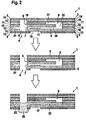
- FIG. 1 shows an analytical test element according to the invention in a sealed, opened and liquid sample applied state.
- the upper picture in FIG. 1 shows the test element 1 in the sealed state. It is made up of a variety of layers. On both outer sides it is sealed by a first and a second sealing layer (2 or 3), which have a low water vapor permeability.
- the first sealing layer 2 closes the sample receiving location 4 and has on its outer side a hydrophobic coating 5, so that an aqueous liquid sample does not wet the outside, but with opened seal at the sample receiving location 4 in the test element 1 arrived.
- a free space 6 is included, into which an inlet opening 7 and a vent opening 8 of a suitable for capillary transport of a liquid sample channel 9 open.
- the channel 9 is U-shaped and extends over several layers, namely two intermediate layers 10, 11 (first and second part of the channel 30, 31) and a carrier layer 12 (opening 32).
- the test element 1 also contains a transparent first carrier layer 13 and a third carrier layer 14 arranged adjacent to the second sealing layer 3.
- the carrier layers 12, 13, 14 form the cover and bottom layers of the channel 9.
- the second and third carrier layers 12, 14 each have on their, the channel 9 side facing a hydrophobic coating 15 and 16, which is intended to prevent the aqueous liquid sample thereof, in the Vent opening 8 facing part of the channel 9 to enter.
- a test field 17 is arranged on the side facing the transparent first carrier layer 13, on which the liquid sample can be analyzed.
- a detection window 18 in the first sealing layer 2 for the photometric analysis of the liquid sample on the test field 17.
- a desiccant In the channel 9 is further placed near the vent 8, a desiccant, the to absorb possible residual moisture in the sealed test element 1.
- the middle picture of the FIG. 1 shows an open test element 1, in which both sealing layers 2, 3 are pierced or cut open in the region of the free space 6.
- the sample receiving site 4 is now open and ready to receive a liquid sample.
- the inlet opening 7 of the channel 9 and the vent opening 8 of the channel 9 have also been simultaneously opened to the surroundings of the test element 1.
- the lower picture of the FIG. 1 shows how the liquid sample 20 reaches the test field 17.
- a sufficiently large drop of the liquid sample 20 is placed on the test element 1, from where the liquid sample 20 passes through the free space 6 to the inlet opening 7 of the channel 9 and is sucked into it by capillary forces.
- the sample 20 flows over the test field 17 where it is analyzed.
- FIG. 2 shows a further inventive analytical test element, the structure of which in FIG. 1 corresponds to the test element shown and additionally has a waste-type area 21, which can receive an excess 22 of liquid sample 20.
- FIG. 1 description given also on the test element 1 according to FIG. 2 to and the reference numbers have the same meaning as in FIG. 1 ,
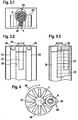
- FIG. 3 schematically shows an inventive system for the analysis of liquid samples.
- FIG. 3 schematically shows a plan view of the system.
- the test elements 1 according to the invention are in the form of a magazine 23 in the form of a magazine.
- An expression cone serves as a compression unit 24 for increasing the pressure on the skin surrounding the body opening of a patient to deliver a body fluid such as blood or interstitial fluid from the body opening.
- the compression unit 24 is arranged above the sample receiving location 4 of a test element 1 located in the working position.
- FIG. 3 schematically shows a first side view of the same system according to the invention.
- the magazine in the form of a belt 23 passes over two transport rollers 25 in order to bring in each case a test element 1 in working position in which the compression unit 24 is located directly above the sample receiving location.
- a cylindrical piercing arrangement 26 (not visible) a piercing device and optionally a perforation device are arranged, which can be brought, for example, by turning a holder holding it one after the other in the working position, ie in a position in which the piercing device, the seal on both sides of the test element.
- the perforation device can produce a body opening in a placed on the compression unit 24 body part.
- a detector 27 for example for the photometric analysis of a sample, which is directed onto a (not shown) detection window in the test element 1 in the working position.
- FIG. 3 schematically shows a second side view of the same system according to the invention.
- the cylindrical arrangement 26, the detector 27, the band-shaped magazine 23 and the compression unit 24 are recognizable.
- FIG. 4 schematically shows another inventive system for analyzing liquid samples in a plan view.
- the system includes a magazine in the form of a diskette 28 on which the test elements 1 according to the invention are arranged radially on a substantially circular disk. By rotating the magazine 28 in the direction of rotation 29, in each case a test element 1 can be brought into the working position (sample receiving location 4 under the compression unit 24).
- the system further includes a piercing device (not shown) housed within a cylindrical assembly 26 and a detector 27.
Landscapes
- Health & Medical Sciences (AREA)
- Chemical & Material Sciences (AREA)
- Life Sciences & Earth Sciences (AREA)
- General Health & Medical Sciences (AREA)
- Chemical Kinetics & Catalysis (AREA)
- Hematology (AREA)
- Analytical Chemistry (AREA)
- Physics & Mathematics (AREA)
- Clinical Laboratory Science (AREA)
- Dispersion Chemistry (AREA)
- Molecular Biology (AREA)
- Pathology (AREA)
- Biophysics (AREA)
- Electrochemistry (AREA)
- Animal Behavior & Ethology (AREA)
- Emergency Medicine (AREA)
- Optics & Photonics (AREA)
- Engineering & Computer Science (AREA)
- Biomedical Technology (AREA)
- Heart & Thoracic Surgery (AREA)
- Medical Informatics (AREA)
- Surgery (AREA)
- Immunology (AREA)
- Public Health (AREA)
- Veterinary Medicine (AREA)
- General Physics & Mathematics (AREA)
- Biochemistry (AREA)
- Investigating Or Analysing Biological Materials (AREA)
- Automatic Analysis And Handling Materials Therefor (AREA)
- Measurement Of The Respiration, Hearing Ability, Form, And Blood Characteristics Of Living Organisms (AREA)
- Polysaccharides And Polysaccharide Derivatives (AREA)
Applications Claiming Priority (2)
| Application Number | Priority Date | Filing Date | Title |
|---|---|---|---|
| DE102004033317A DE102004033317A1 (de) | 2004-07-09 | 2004-07-09 | Analytisches Testelement |
| PCT/EP2005/007251 WO2006005483A1 (de) | 2004-07-09 | 2005-07-05 | Analytisches testelement |
Publications (2)
| Publication Number | Publication Date |
|---|---|
| EP1789192A1 EP1789192A1 (de) | 2007-05-30 |
| EP1789192B1 true EP1789192B1 (de) | 2009-09-16 |
Family
ID=34971594
Family Applications (1)
| Application Number | Title | Priority Date | Filing Date |
|---|---|---|---|
| EP05756366A Expired - Lifetime EP1789192B1 (de) | 2004-07-09 | 2005-07-05 | Analytisches testelement |
Country Status (8)
| Country | Link |
|---|---|
| US (1) | US8252248B2 (enExample) |
| EP (1) | EP1789192B1 (enExample) |
| JP (1) | JP2008505330A (enExample) |
| CN (1) | CN1984716A (enExample) |
| AT (1) | ATE442903T1 (enExample) |
| CA (1) | CA2567009A1 (enExample) |
| DE (2) | DE102004033317A1 (enExample) |
| WO (1) | WO2006005483A1 (enExample) |
Families Citing this family (93)
| Publication number | Priority date | Publication date | Assignee | Title |
|---|---|---|---|---|
| US6391005B1 (en) | 1998-03-30 | 2002-05-21 | Agilent Technologies, Inc. | Apparatus and method for penetration with shaft having a sensor for sensing penetration depth |
| US8641644B2 (en) | 2000-11-21 | 2014-02-04 | Sanofi-Aventis Deutschland Gmbh | Blood testing apparatus having a rotatable cartridge with multiple lancing elements and testing means |
| EP1404233B1 (en) | 2001-06-12 | 2009-12-02 | Pelikan Technologies Inc. | Self optimizing lancing device with adaptation means to temporal variations in cutaneous properties |
| AU2002348683A1 (en) | 2001-06-12 | 2002-12-23 | Pelikan Technologies, Inc. | Method and apparatus for lancet launching device integrated onto a blood-sampling cartridge |
| US7041068B2 (en) | 2001-06-12 | 2006-05-09 | Pelikan Technologies, Inc. | Sampling module device and method |
| CA2448790C (en) | 2001-06-12 | 2010-09-07 | Pelikan Technologies, Inc. | Electric lancet actuator |
| US7344507B2 (en) | 2002-04-19 | 2008-03-18 | Pelikan Technologies, Inc. | Method and apparatus for lancet actuation |
| US9795747B2 (en) | 2010-06-02 | 2017-10-24 | Sanofi-Aventis Deutschland Gmbh | Methods and apparatus for lancet actuation |
| US7981056B2 (en) | 2002-04-19 | 2011-07-19 | Pelikan Technologies, Inc. | Methods and apparatus for lancet actuation |
| US8337419B2 (en) | 2002-04-19 | 2012-12-25 | Sanofi-Aventis Deutschland Gmbh | Tissue penetration device |
| US9226699B2 (en) | 2002-04-19 | 2016-01-05 | Sanofi-Aventis Deutschland Gmbh | Body fluid sampling module with a continuous compression tissue interface surface |
| US9427532B2 (en) | 2001-06-12 | 2016-08-30 | Sanofi-Aventis Deutschland Gmbh | Tissue penetration device |
| US8360992B2 (en) | 2002-04-19 | 2013-01-29 | Sanofi-Aventis Deutschland Gmbh | Method and apparatus for penetrating tissue |
| US7976476B2 (en) | 2002-04-19 | 2011-07-12 | Pelikan Technologies, Inc. | Device and method for variable speed lancet |
| US9795334B2 (en) | 2002-04-19 | 2017-10-24 | Sanofi-Aventis Deutschland Gmbh | Method and apparatus for penetrating tissue |
| US8784335B2 (en) | 2002-04-19 | 2014-07-22 | Sanofi-Aventis Deutschland Gmbh | Body fluid sampling device with a capacitive sensor |
| US8221334B2 (en) | 2002-04-19 | 2012-07-17 | Sanofi-Aventis Deutschland Gmbh | Method and apparatus for penetrating tissue |
| US9248267B2 (en) | 2002-04-19 | 2016-02-02 | Sanofi-Aventis Deustchland Gmbh | Tissue penetration device |
| US7547287B2 (en) | 2002-04-19 | 2009-06-16 | Pelikan Technologies, Inc. | Method and apparatus for penetrating tissue |
| US7901362B2 (en) | 2002-04-19 | 2011-03-08 | Pelikan Technologies, Inc. | Method and apparatus for penetrating tissue |
| US7229458B2 (en) | 2002-04-19 | 2007-06-12 | Pelikan Technologies, Inc. | Method and apparatus for penetrating tissue |
| US7491178B2 (en) | 2002-04-19 | 2009-02-17 | Pelikan Technologies, Inc. | Method and apparatus for penetrating tissue |
| US7892183B2 (en) | 2002-04-19 | 2011-02-22 | Pelikan Technologies, Inc. | Method and apparatus for body fluid sampling and analyte sensing |
| US8702624B2 (en) | 2006-09-29 | 2014-04-22 | Sanofi-Aventis Deutschland Gmbh | Analyte measurement device with a single shot actuator |
| US7892185B2 (en) | 2002-04-19 | 2011-02-22 | Pelikan Technologies, Inc. | Method and apparatus for body fluid sampling and analyte sensing |
| US7909778B2 (en) | 2002-04-19 | 2011-03-22 | Pelikan Technologies, Inc. | Method and apparatus for penetrating tissue |
| US8579831B2 (en) | 2002-04-19 | 2013-11-12 | Sanofi-Aventis Deutschland Gmbh | Method and apparatus for penetrating tissue |
| US9314194B2 (en) | 2002-04-19 | 2016-04-19 | Sanofi-Aventis Deutschland Gmbh | Tissue penetration device |
| US7297122B2 (en) | 2002-04-19 | 2007-11-20 | Pelikan Technologies, Inc. | Method and apparatus for penetrating tissue |
| US8267870B2 (en) | 2002-04-19 | 2012-09-18 | Sanofi-Aventis Deutschland Gmbh | Method and apparatus for body fluid sampling with hybrid actuation |
| US7331931B2 (en) | 2002-04-19 | 2008-02-19 | Pelikan Technologies, Inc. | Method and apparatus for penetrating tissue |
| US7226461B2 (en) | 2002-04-19 | 2007-06-05 | Pelikan Technologies, Inc. | Method and apparatus for a multi-use body fluid sampling device with sterility barrier release |
| US7674232B2 (en) | 2002-04-19 | 2010-03-09 | Pelikan Technologies, Inc. | Method and apparatus for penetrating tissue |
| US7232451B2 (en) | 2002-04-19 | 2007-06-19 | Pelikan Technologies, Inc. | Method and apparatus for penetrating tissue |
| US8574895B2 (en) | 2002-12-30 | 2013-11-05 | Sanofi-Aventis Deutschland Gmbh | Method and apparatus using optical techniques to measure analyte levels |
| WO2004107975A2 (en) | 2003-05-30 | 2004-12-16 | Pelikan Technologies, Inc. | Method and apparatus for fluid injection |
| WO2004107964A2 (en) | 2003-06-06 | 2004-12-16 | Pelikan Technologies, Inc. | Blood harvesting device with electronic control |
| WO2006001797A1 (en) | 2004-06-14 | 2006-01-05 | Pelikan Technologies, Inc. | Low pain penetrating |
| US8282576B2 (en) | 2003-09-29 | 2012-10-09 | Sanofi-Aventis Deutschland Gmbh | Method and apparatus for an improved sample capture device |
| WO2005037095A1 (en) | 2003-10-14 | 2005-04-28 | Pelikan Technologies, Inc. | Method and apparatus for a variable user interface |
| WO2005065414A2 (en) | 2003-12-31 | 2005-07-21 | Pelikan Technologies, Inc. | Method and apparatus for improving fluidic flow and sample capture |
| US7822454B1 (en) | 2005-01-03 | 2010-10-26 | Pelikan Technologies, Inc. | Fluid sampling device with improved analyte detecting member configuration |
| WO2006011062A2 (en) | 2004-05-20 | 2006-02-02 | Albatros Technologies Gmbh & Co. Kg | Printable hydrogel for biosensors |
| WO2005120365A1 (en) | 2004-06-03 | 2005-12-22 | Pelikan Technologies, Inc. | Method and apparatus for a fluid sampling device |
| US9775553B2 (en) | 2004-06-03 | 2017-10-03 | Sanofi-Aventis Deutschland Gmbh | Method and apparatus for a fluid sampling device |
| US20090054811A1 (en) * | 2004-12-30 | 2009-02-26 | Dirk Boecker | Method and apparatus for analyte measurement test time |
| US8652831B2 (en) * | 2004-12-30 | 2014-02-18 | Sanofi-Aventis Deutschland Gmbh | Method and apparatus for analyte measurement test time |
| US7794656B2 (en) | 2006-01-23 | 2010-09-14 | Quidel Corporation | Device for handling and analysis of a biological sample |
| US7871568B2 (en) | 2006-01-23 | 2011-01-18 | Quidel Corporation | Rapid test apparatus |
| JP2010525322A (ja) | 2007-04-20 | 2010-07-22 | クイデル コーポレイション | 統合乾燥剤付きの分析装置 |
| WO2008145628A1 (en) * | 2007-05-29 | 2008-12-04 | F. Hoffmann-La Roche Ag | Test element magazine |
| WO2009126900A1 (en) | 2008-04-11 | 2009-10-15 | Pelikan Technologies, Inc. | Method and apparatus for analyte detecting device |
| EP2145683A1 (de) * | 2008-07-14 | 2010-01-20 | F.Hoffmann-La Roche Ag | Analytisches Testelement mit hydrophil modifizierter Oberfläche |
| US9375169B2 (en) | 2009-01-30 | 2016-06-28 | Sanofi-Aventis Deutschland Gmbh | Cam drive for managing disposable penetrating member actions with a single motor and motor and control system |
| EP2322924A1 (de) | 2009-10-15 | 2011-05-18 | F. Hoffmann-La Roche AG | Schutz vor hydrophobierenden Agenzien |
| US8965476B2 (en) | 2010-04-16 | 2015-02-24 | Sanofi-Aventis Deutschland Gmbh | Tissue penetration device |
| WO2012011074A2 (en) | 2010-07-22 | 2012-01-26 | Hach Company | Lab-on-a-chip for alkalinity analysis |
| WO2012048150A1 (en) * | 2010-10-06 | 2012-04-12 | Profusa, Inc. | Tissue-integrating sensors |
| FR2966368B1 (fr) * | 2010-10-22 | 2014-02-28 | Biomerieux Sa | Procede pour isoler un puits a echantillon d'une carte test pour analyse et carte test obtenue |
| WO2012081695A1 (ja) * | 2010-12-17 | 2012-06-21 | 株式会社堀場製作所 | 被検液分析用チップ |
| CN107884560A (zh) | 2012-04-04 | 2018-04-06 | 辛辛那提大学 | 汗液模拟、收集和感测系统 |
| US9180449B2 (en) | 2012-06-12 | 2015-11-10 | Hach Company | Mobile water analysis |
| EP2893027B1 (en) * | 2012-09-06 | 2016-10-19 | Roche Diabetes Care GmbH | Improved matrix stability compositions and methods |
| USD768872S1 (en) | 2012-12-12 | 2016-10-11 | Hach Company | Cuvette for a water analysis instrument |
| GB2509140B (en) * | 2012-12-21 | 2015-12-30 | Lifescan Scotland Ltd | Analytical test strip with tiered capillary chamber |
| US10888244B2 (en) | 2013-10-18 | 2021-01-12 | University Of Cincinnati | Sweat sensing with chronological assurance |
| US10136831B2 (en) | 2013-10-18 | 2018-11-27 | University Of Cincinnati | Sweat sensing with chronological assurance |
| CA2927211A1 (en) | 2013-10-18 | 2015-04-23 | University Of Cincinnati | Devices for integrated, repeated, prolonged, and/or reliable sweat stimulation and biosensing |
| WO2015184072A1 (en) | 2014-05-28 | 2015-12-03 | University Of Cincinnati | Advanced sweat sensor adhesion, sealing, and fluidic strategies |
| WO2015184097A2 (en) | 2014-05-28 | 2015-12-03 | University Of Cincinnati | Devices with reduced sweat volumes between sensors and sweat glands |
| WO2015184084A2 (en) | 2014-05-28 | 2015-12-03 | University Of Cincinnati | Sweat monitoring and control of drug delivery |
| WO2016049019A1 (en) | 2014-09-22 | 2016-03-31 | University Of Cincinnati | Sweat sensing with analytical assurance |
| CN111067544B (zh) | 2015-02-13 | 2023-04-07 | 辛辛那提大学 | 集成间接汗液刺激和感测的装置 |
| US10646142B2 (en) | 2015-06-29 | 2020-05-12 | Eccrine Systems, Inc. | Smart sweat stimulation and sensing devices |
| US20180235522A1 (en) * | 2015-09-09 | 2018-08-23 | University Of Cincinnati | Mechanically co-located sweat stimulation and sensing |
| US20180317833A1 (en) | 2015-10-23 | 2018-11-08 | Eccrine Systems, Inc. | Devices capable of fluid sample concentration for extended sensing of analytes |
| EP3367891B1 (en) | 2015-10-30 | 2024-08-14 | University of Cincinnati | Sweat sensing devices with electromagnetically shielded sensors, interconnects, and electronics |
| US10674946B2 (en) | 2015-12-18 | 2020-06-09 | Eccrine Systems, Inc. | Sweat sensing devices with sensor abrasion protection |
| US10073092B2 (en) | 2016-02-19 | 2018-09-11 | Andrew Wang | Apparatus for assay strip(s) with specimen loading to multiple zones and related methods |
| US10471249B2 (en) | 2016-06-08 | 2019-11-12 | University Of Cincinnati | Enhanced analyte access through epithelial tissue |
| WO2018006087A1 (en) | 2016-07-01 | 2018-01-04 | University Of Cincinnati | Devices with reduced microfluidic volume between sensors and sweat glands |
| EP3487390A4 (en) | 2016-07-19 | 2020-03-11 | Eccrine Systems, Inc. | DEVICES AND APPLICATIONS FOR WELDING CONDUCTIVITY, VOLUMETRIC WELDING RATE AND GALVANIC SKIN REACTION |
| CN109843372B (zh) | 2016-08-19 | 2023-06-16 | 辛辛那提大学 | 长时间汗液刺激 |
| CN109789410B (zh) * | 2016-10-07 | 2022-06-10 | 勃林格殷格翰维特梅迪卡有限公司 | 用于测试样品的储物筒 |
| US10736565B2 (en) | 2016-10-14 | 2020-08-11 | Eccrine Systems, Inc. | Sweat electrolyte loss monitoring devices |
| CN108937892A (zh) * | 2018-08-31 | 2018-12-07 | 安徽国科生物科技有限公司 | 一种体质诊疗系统 |
| EP3861211A1 (en) | 2018-10-01 | 2021-08-11 | Boehringer Ingelheim Vetmedica GmbH | Peristaltic pump and analyzer for testing a sample |
| CN110339879B (zh) * | 2019-07-10 | 2021-06-18 | 深圳金迈隆电子技术有限公司 | 一种片上实验室的制造方法 |
| EP3822634B1 (en) * | 2019-11-14 | 2025-09-24 | Apex Biotechnology Corporation | Biosensor strip |
| EP4126358A4 (en) * | 2020-04-03 | 2023-12-13 | Revosketch Inc. | CASSETTE FOR SANDWICH ELISA WITH PRE-LOADED ANTIGEN-SPECIFIC DETECTION REAGENT AND SANDWICH ELISA DEVICE WITH THE CASSETTE |
| CN114100702B (zh) * | 2020-08-27 | 2023-05-30 | 京东方科技集团股份有限公司 | 一种检测芯片及其制备方法、使用方法、检测装置 |
| TWI767323B (zh) * | 2020-09-11 | 2022-06-11 | 馬縈嬛 | 生物晶片檢測裝置及其方法 |
| CN113243892A (zh) * | 2021-06-28 | 2021-08-13 | 遵义医科大学附属医院 | 多功能疼痛评估模具 |
Family Cites Families (53)
| Publication number | Priority date | Publication date | Assignee | Title |
|---|---|---|---|---|
| DE1020296B (de) | 1954-02-24 | 1957-12-05 | Hemscheidt Maschf Hermann | Vorrichtung zur Bildung und Verwertung einer Haftmasse als Staubbindemittel, insbesondere fuer Kohlenstaub unter Verwendung angesaugten Kohlenstaubes |
| US4473457A (en) * | 1982-03-29 | 1984-09-25 | Eastman Kodak Company | Liquid transport device providing diversion of capillary flow into a non-vented second zone |
| US4549952A (en) * | 1982-11-22 | 1985-10-29 | Eastman Kodak Company | Capillary transport device having means for increasing the viscosity of the transported liquid |
| US4654127A (en) * | 1984-04-11 | 1987-03-31 | Sentech Medical Corporation | Self-calibrating single-use sensing device for clinical chemistry and method of use |
| WO1986006488A1 (en) * | 1985-04-29 | 1986-11-06 | Hichem Diagnostics, Inc., Dba Bural Technologies | Diagnostic test kit |
| AT396998B (de) * | 1985-12-09 | 1994-01-25 | Ottosensors Corp | Messeinrichtungen und rohranschluss sowie verfahren zur herstellung einer messeinrichtung und verfahren zur verbindung von rohren mit einer messeinrichtung bzw. zur herstellung von rohranschlüssen |
| AT393565B (de) * | 1988-08-09 | 1991-11-11 | Avl Verbrennungskraft Messtech | Einweg-messelement |
| US5035704A (en) * | 1989-03-07 | 1991-07-30 | Lambert Robert D | Blood sampling mechanism |
| US4957582A (en) * | 1989-03-16 | 1990-09-18 | Eastman Kodak Company | Capillary transport zone coated with adhesive |
| US5208163A (en) * | 1990-08-06 | 1993-05-04 | Miles Inc. | Self-metering fluid analysis device |
| US5207984A (en) * | 1991-03-11 | 1993-05-04 | Miles Inc. | Blood sample collection and test device |
| US5508308A (en) * | 1992-04-16 | 1996-04-16 | Abbott Laboratories | Use of pyruvylglycine to treat ischemia/reperfusion injury following myocardial infarction |
| US5744366A (en) * | 1992-05-01 | 1998-04-28 | Trustees Of The University Of Pennsylvania | Mesoscale devices and methods for analysis of motile cells |
| US5354692A (en) * | 1992-09-08 | 1994-10-11 | Pacific Biotech, Inc. | Analyte detection device including a hydrophobic barrier for improved fluid flow |
| US5500187A (en) * | 1992-12-08 | 1996-03-19 | Westinghouse Electric Corporation | Disposable optical agglutination assay device and method for use |
| EP0622119B1 (de) * | 1993-04-23 | 1999-11-03 | Roche Diagnostics GmbH | System zur Bevorratung und Zurverfügungstellung von Testelementen |
| DE4328815A1 (de) | 1993-08-27 | 1995-03-02 | Boehringer Mannheim Gmbh | System zur Bevorratung von Testelementen |
| US5630986A (en) | 1995-01-13 | 1997-05-20 | Bayer Corporation | Dispensing instrument for fluid monitoring sensors |
| US5636640A (en) * | 1995-02-06 | 1997-06-10 | Volunteers For Medical Engineering | Liquid sampling and test apparatus |
| CA2170560C (en) | 1995-04-17 | 2005-10-25 | Joseph L. Moulton | Means of handling multiple sensors in a glucose monitoring instrument system |
| US5589136A (en) * | 1995-06-20 | 1996-12-31 | Regents Of The University Of California | Silicon-based sleeve devices for chemical reactions |
| US5863502A (en) * | 1996-01-24 | 1999-01-26 | Sarnoff Corporation | Parallel reaction cassette and associated devices |
| US5683502A (en) * | 1996-04-29 | 1997-11-04 | Bayer Corporation | Incorporation of aromatic polycyclic compounds in quinacridone processes |
| US5964718A (en) * | 1997-11-21 | 1999-10-12 | Mercury Diagnostics, Inc. | Body fluid sampling device |
| US6071294A (en) * | 1997-12-04 | 2000-06-06 | Agilent Technologies, Inc. | Lancet cartridge for sampling blood |
| DE19753847A1 (de) * | 1997-12-04 | 1999-06-10 | Roche Diagnostics Gmbh | Analytisches Testelement mit Kapillarkanal |
| JP3896435B2 (ja) * | 1997-12-17 | 2007-03-22 | アークレイ株式会社 | センサおよびセンサ集合体 |
| DE19854316A1 (de) | 1998-04-24 | 1999-10-28 | Roche Diagnostics Gmbh | Vorratsbehältnis für analytische Hilfsmittel |
| SG102538A1 (en) * | 1998-04-24 | 2004-03-26 | Roche Diagnostics Gmbh | Storage container for analytical devices |
| DE19819407A1 (de) | 1998-04-30 | 1999-11-11 | Hendrik Priebs | Teststreifenbehälter für Messgeräte, die mit Einwegteststreifen arbeiten |
| US6572830B1 (en) * | 1998-10-09 | 2003-06-03 | Motorola, Inc. | Integrated multilayered microfludic devices and methods for making the same |
| DE19902601A1 (de) * | 1999-01-23 | 2000-07-27 | Roche Diagnostics Gmbh | Verfahren und Vorrichtung zum Entnehmen analytischer Verbrauchsmittel aus einem Vorratsbehältnis |
| DE10001116C2 (de) * | 2000-01-13 | 2002-11-28 | Meinhard Knoll | Vorrichtung und Verfahren zur optischen oder elektrochemischen quantitativen Bestimmung chemischer oder biochemischer Substanzen in flüssigen Proben |
| US6451264B1 (en) * | 2000-01-28 | 2002-09-17 | Roche Diagnostics Corporation | Fluid flow control in curved capillary channels |
| JP4733331B2 (ja) * | 2000-03-14 | 2011-07-27 | マイクロニックス、インコーポレーテッド | マイクロ流動体分析用デバイス |
| US6431212B1 (en) * | 2000-05-24 | 2002-08-13 | Jon W. Hayenga | Valve for use in microfluidic structures |
| US6557427B2 (en) * | 2000-05-24 | 2003-05-06 | Micronics, Inc. | Capillaries for fluid movement within microfluidic channels |
| DE10026172A1 (de) | 2000-05-26 | 2001-11-29 | Roche Diagnostics Gmbh | System zur Entnahme von Körperflüssigkeit |
| GB0017737D0 (en) | 2000-07-20 | 2000-09-06 | Hypoguard Limited | Test device |
| US20020048819A1 (en) * | 2000-10-24 | 2002-04-25 | Kenneth Alley | Test strip for use in an apparatus for sampling and testing a specimen |
| DK1201304T3 (da) * | 2000-10-25 | 2006-11-13 | Boehringer Ingelheim Micropart | Mikrostruktureret platform til undersögelse af en væske |
| DE10057832C1 (de) | 2000-11-21 | 2002-02-21 | Hartmann Paul Ag | Blutanalysegerät |
| AU784254B2 (en) * | 2001-05-21 | 2006-03-02 | Bayer Corporation | Improved electrochemical sensor |
| US6919046B2 (en) * | 2001-06-07 | 2005-07-19 | Nanostream, Inc. | Microfluidic analytical devices and methods |
| CA2450114A1 (en) * | 2001-06-08 | 2002-12-19 | F. Hoffmann-La Roche Ag | Sampling devices and methods utilizing a horizontal capillary test strip |
| US20030028125A1 (en) * | 2001-08-06 | 2003-02-06 | Yuzhakov Vadim V. | Physiological sample collection devices and methods of using the same |
| CA2458208A1 (en) * | 2001-08-29 | 2003-03-13 | F. Hoffmann-La Roche Ag | Wicking methods and structures for use in sampling bodily fluids |
| DE10220296A1 (de) * | 2002-05-07 | 2003-11-20 | Roche Diagnostics Gmbh | Vorrichtung zur Probennahme von flüssigen Proben |
| EP1534430A4 (en) * | 2002-07-26 | 2005-11-23 | Applera Corp | DEVICES, SYSTEMS AND METHODS FOR EXCLUSION OF MICROFLUIDIC SIZE |
| US6939450B2 (en) * | 2002-10-08 | 2005-09-06 | Abbott Laboratories | Device having a flow channel |
| JP4119217B2 (ja) * | 2002-10-10 | 2008-07-16 | 財団法人川村理化学研究所 | マイクロ流体素子、流体処理デバイス、および流体処理方法 |
| WO2004091403A1 (en) * | 2003-04-15 | 2004-10-28 | Optiscan Biomedical Corporation | Sample element with barrier material |
| US7374949B2 (en) | 2003-05-29 | 2008-05-20 | Bayer Healthcare Llc | Diagnostic test strip for collecting and detecting an analyte in a fluid sample |
-
2004
- 2004-07-09 DE DE102004033317A patent/DE102004033317A1/de not_active Ceased
-
2005
- 2005-07-05 CN CNA2005800232366A patent/CN1984716A/zh active Pending
- 2005-07-05 DE DE502005008149T patent/DE502005008149D1/de not_active Expired - Lifetime
- 2005-07-05 CA CA002567009A patent/CA2567009A1/en not_active Abandoned
- 2005-07-05 JP JP2007519702A patent/JP2008505330A/ja active Pending
- 2005-07-05 AT AT05756366T patent/ATE442903T1/de not_active IP Right Cessation
- 2005-07-05 US US11/632,083 patent/US8252248B2/en not_active Expired - Fee Related
- 2005-07-05 EP EP05756366A patent/EP1789192B1/de not_active Expired - Lifetime
- 2005-07-05 WO PCT/EP2005/007251 patent/WO2006005483A1/de not_active Ceased
Also Published As
| Publication number | Publication date |
|---|---|
| DE502005008149D1 (de) | 2009-10-29 |
| CA2567009A1 (en) | 2006-01-19 |
| US20080031778A1 (en) | 2008-02-07 |
| JP2008505330A (ja) | 2008-02-21 |
| CN1984716A (zh) | 2007-06-20 |
| WO2006005483A1 (de) | 2006-01-19 |
| US8252248B2 (en) | 2012-08-28 |
| EP1789192A1 (de) | 2007-05-30 |
| ATE442903T1 (de) | 2009-10-15 |
| DE102004033317A1 (de) | 2006-02-09 |
Similar Documents
| Publication | Publication Date | Title |
|---|---|---|
| EP1789192B1 (de) | Analytisches testelement | |
| EP0949002B1 (de) | Verfahren zur Herstellung von analytischen Hilfsmitteln | |
| EP1035920B1 (de) | Kapillaraktives testelement mit träger und abdeckung | |
| EP1035921B1 (de) | Analytisches testelement mit kapillarkanal | |
| EP1705480B1 (de) | Testelement zur Analyse von Körperflüssigkeiten | |
| EP0951939B1 (de) | Vorratsbehältnis für analytische Hilfsmittel | |
| DE69825107T2 (de) | Unterdruckerzeugungsvorrichtung und Probenanalysenvorrichtung zur Verwendung mit einer solchen Unterdruckerzeugungsvorrichtung | |
| DE60310160T2 (de) | Streifen zur Verpackung einer Mehrzahl von Geräten zur Flüssigkeitsentnahme und Testung sowie Verfahren zur Herstellung und Verwendung des Streifens | |
| EP1036330A1 (de) | Analytisches testelement mit sich verjüngendem kapillarkanal | |
| EP0637749A2 (de) | System zur Analyse von Probenflüssigkeiten | |
| DE3151291A1 (de) | Geraet zur analyse von biologischen fluiden | |
| EP0622626A2 (de) | System zur Analyse von Inhaltsstoffen flüssiger Proben | |
| EP1035919B1 (de) | Vorrichtung zum kapillaren flüssigkeitstransport | |
| EP1522343A1 (de) | Analytisches Testelement umfassend ein Netzwerk zur Bildung eines Kapillarkanals | |
| EP1507589B1 (de) | Vorrichtung zur probennahme von flüssigen proben | |
| EP1690087B1 (de) | Beschichtete testelemente | |
| DE102018105174A1 (de) | Analyseeinheit | |
| EP1914547A1 (de) | Vorrichtung, Messgerät und Verfahren zur Handhabung mikrofluidischer Plattformen | |
| DE19854316A1 (de) | Vorratsbehältnis für analytische Hilfsmittel | |
| EP2389097B1 (de) | System und verfahren zur analyse einer körperflüssigkeit | |
| WO2019030584A1 (de) | Sensorelement und dessen verwendung | |
| EP3073922B1 (de) | Einzelverpackte einweg-bluttesteinheit | |
| DE102023121081A1 (de) | Mikrofluidischer Testträger | |
| DE102023121083A1 (de) | Fluidspeichernde Testträger-Kanalstruktur und mikrofluidischer Testträger | |
| DE102023121082A1 (de) | Reaktionskammereinheit und mikrofluidischer Testträger |
Legal Events
| Date | Code | Title | Description |
|---|---|---|---|
| PUAI | Public reference made under article 153(3) epc to a published international application that has entered the european phase |
Free format text: ORIGINAL CODE: 0009012 |
|
| 17P | Request for examination filed |
Effective date: 20070206 |
|
| AK | Designated contracting states |
Kind code of ref document: A1 Designated state(s): AT BE BG CH CY CZ DE DK EE ES FI FR GB GR HU IE IS IT LI LT LU LV MC NL PL PT RO SE SI SK TR |
|
| DAX | Request for extension of the european patent (deleted) | ||
| 17Q | First examination report despatched |
Effective date: 20080318 |
|
| GRAP | Despatch of communication of intention to grant a patent |
Free format text: ORIGINAL CODE: EPIDOSNIGR1 |
|
| GRAS | Grant fee paid |
Free format text: ORIGINAL CODE: EPIDOSNIGR3 |
|
| GRAA | (expected) grant |
Free format text: ORIGINAL CODE: 0009210 |
|
| AK | Designated contracting states |
Kind code of ref document: B1 Designated state(s): AT BE BG CH CY CZ DE DK EE ES FI FR GB GR HU IE IS IT LI LT LU LV MC NL PL PT RO SE SI SK TR |
|
| REG | Reference to a national code |
Ref country code: GB Ref legal event code: FG4D Free format text: NOT ENGLISH |
|
| REG | Reference to a national code |
Ref country code: CH Ref legal event code: EP |
|
| REG | Reference to a national code |
Ref country code: IE Ref legal event code: FG4D |
|
| REF | Corresponds to: |
Ref document number: 502005008149 Country of ref document: DE Date of ref document: 20091029 Kind code of ref document: P |
|
| PG25 | Lapsed in a contracting state [announced via postgrant information from national office to epo] |
Ref country code: SE Free format text: LAPSE BECAUSE OF FAILURE TO SUBMIT A TRANSLATION OF THE DESCRIPTION OR TO PAY THE FEE WITHIN THE PRESCRIBED TIME-LIMIT Effective date: 20090916 Ref country code: FI Free format text: LAPSE BECAUSE OF FAILURE TO SUBMIT A TRANSLATION OF THE DESCRIPTION OR TO PAY THE FEE WITHIN THE PRESCRIBED TIME-LIMIT Effective date: 20090916 Ref country code: LT Free format text: LAPSE BECAUSE OF FAILURE TO SUBMIT A TRANSLATION OF THE DESCRIPTION OR TO PAY THE FEE WITHIN THE PRESCRIBED TIME-LIMIT Effective date: 20090916 |
|
| LTIE | Lt: invalidation of european patent or patent extension |
Effective date: 20090916 |
|
| PG25 | Lapsed in a contracting state [announced via postgrant information from national office to epo] |
Ref country code: LV Free format text: LAPSE BECAUSE OF FAILURE TO SUBMIT A TRANSLATION OF THE DESCRIPTION OR TO PAY THE FEE WITHIN THE PRESCRIBED TIME-LIMIT Effective date: 20090916 Ref country code: SI Free format text: LAPSE BECAUSE OF FAILURE TO SUBMIT A TRANSLATION OF THE DESCRIPTION OR TO PAY THE FEE WITHIN THE PRESCRIBED TIME-LIMIT Effective date: 20090916 Ref country code: NL Free format text: LAPSE BECAUSE OF FAILURE TO SUBMIT A TRANSLATION OF THE DESCRIPTION OR TO PAY THE FEE WITHIN THE PRESCRIBED TIME-LIMIT Effective date: 20090916 Ref country code: PL Free format text: LAPSE BECAUSE OF FAILURE TO SUBMIT A TRANSLATION OF THE DESCRIPTION OR TO PAY THE FEE WITHIN THE PRESCRIBED TIME-LIMIT Effective date: 20090916 |
|
| NLV1 | Nl: lapsed or annulled due to failure to fulfill the requirements of art. 29p and 29m of the patents act | ||
| PG25 | Lapsed in a contracting state [announced via postgrant information from national office to epo] |
Ref country code: CY Free format text: LAPSE BECAUSE OF FAILURE TO SUBMIT A TRANSLATION OF THE DESCRIPTION OR TO PAY THE FEE WITHIN THE PRESCRIBED TIME-LIMIT Effective date: 20090916 |
|
| REG | Reference to a national code |
Ref country code: IE Ref legal event code: FD4D |
|
| PG25 | Lapsed in a contracting state [announced via postgrant information from national office to epo] |
Ref country code: RO Free format text: LAPSE BECAUSE OF FAILURE TO SUBMIT A TRANSLATION OF THE DESCRIPTION OR TO PAY THE FEE WITHIN THE PRESCRIBED TIME-LIMIT Effective date: 20090916 Ref country code: IE Free format text: LAPSE BECAUSE OF FAILURE TO SUBMIT A TRANSLATION OF THE DESCRIPTION OR TO PAY THE FEE WITHIN THE PRESCRIBED TIME-LIMIT Effective date: 20090916 Ref country code: EE Free format text: LAPSE BECAUSE OF FAILURE TO SUBMIT A TRANSLATION OF THE DESCRIPTION OR TO PAY THE FEE WITHIN THE PRESCRIBED TIME-LIMIT Effective date: 20090916 Ref country code: ES Free format text: LAPSE BECAUSE OF FAILURE TO SUBMIT A TRANSLATION OF THE DESCRIPTION OR TO PAY THE FEE WITHIN THE PRESCRIBED TIME-LIMIT Effective date: 20091227 Ref country code: PT Free format text: LAPSE BECAUSE OF FAILURE TO SUBMIT A TRANSLATION OF THE DESCRIPTION OR TO PAY THE FEE WITHIN THE PRESCRIBED TIME-LIMIT Effective date: 20100118 Ref country code: IS Free format text: LAPSE BECAUSE OF FAILURE TO SUBMIT A TRANSLATION OF THE DESCRIPTION OR TO PAY THE FEE WITHIN THE PRESCRIBED TIME-LIMIT Effective date: 20100116 Ref country code: CZ Free format text: LAPSE BECAUSE OF FAILURE TO SUBMIT A TRANSLATION OF THE DESCRIPTION OR TO PAY THE FEE WITHIN THE PRESCRIBED TIME-LIMIT Effective date: 20090916 |
|
| PG25 | Lapsed in a contracting state [announced via postgrant information from national office to epo] |
Ref country code: SK Free format text: LAPSE BECAUSE OF FAILURE TO SUBMIT A TRANSLATION OF THE DESCRIPTION OR TO PAY THE FEE WITHIN THE PRESCRIBED TIME-LIMIT Effective date: 20090916 |
|
| PLBE | No opposition filed within time limit |
Free format text: ORIGINAL CODE: 0009261 |
|
| STAA | Information on the status of an ep patent application or granted ep patent |
Free format text: STATUS: NO OPPOSITION FILED WITHIN TIME LIMIT |
|
| PG25 | Lapsed in a contracting state [announced via postgrant information from national office to epo] |
Ref country code: DK Free format text: LAPSE BECAUSE OF FAILURE TO SUBMIT A TRANSLATION OF THE DESCRIPTION OR TO PAY THE FEE WITHIN THE PRESCRIBED TIME-LIMIT Effective date: 20090916 |
|
| 26N | No opposition filed |
Effective date: 20100617 |
|
| PG25 | Lapsed in a contracting state [announced via postgrant information from national office to epo] |
Ref country code: GR Free format text: LAPSE BECAUSE OF FAILURE TO SUBMIT A TRANSLATION OF THE DESCRIPTION OR TO PAY THE FEE WITHIN THE PRESCRIBED TIME-LIMIT Effective date: 20091217 |
|
| BERE | Be: lapsed |
Owner name: F.HOFFMANN-LA ROCHE A.G. Effective date: 20100731 Owner name: ROCHE DIAGNOSTICS G.M.B.H. Effective date: 20100731 |
|
| PG25 | Lapsed in a contracting state [announced via postgrant information from national office to epo] |
Ref country code: MC Free format text: LAPSE BECAUSE OF NON-PAYMENT OF DUE FEES Effective date: 20100731 |
|
| REG | Reference to a national code |
Ref country code: CH Ref legal event code: PL |
|
| PG25 | Lapsed in a contracting state [announced via postgrant information from national office to epo] |
Ref country code: LI Free format text: LAPSE BECAUSE OF NON-PAYMENT OF DUE FEES Effective date: 20100731 Ref country code: CH Free format text: LAPSE BECAUSE OF NON-PAYMENT OF DUE FEES Effective date: 20100731 |
|
| PG25 | Lapsed in a contracting state [announced via postgrant information from national office to epo] |
Ref country code: BE Free format text: LAPSE BECAUSE OF NON-PAYMENT OF DUE FEES Effective date: 20100731 |
|
| PG25 | Lapsed in a contracting state [announced via postgrant information from national office to epo] |
Ref country code: AT Free format text: LAPSE BECAUSE OF NON-PAYMENT OF DUE FEES Effective date: 20100705 |
|
| PG25 | Lapsed in a contracting state [announced via postgrant information from national office to epo] |
Ref country code: BG Free format text: LAPSE BECAUSE OF FAILURE TO SUBMIT A TRANSLATION OF THE DESCRIPTION OR TO PAY THE FEE WITHIN THE PRESCRIBED TIME-LIMIT Effective date: 20090916 Ref country code: LU Free format text: LAPSE BECAUSE OF NON-PAYMENT OF DUE FEES Effective date: 20100705 Ref country code: HU Free format text: LAPSE BECAUSE OF FAILURE TO SUBMIT A TRANSLATION OF THE DESCRIPTION OR TO PAY THE FEE WITHIN THE PRESCRIBED TIME-LIMIT Effective date: 20100317 |
|
| PG25 | Lapsed in a contracting state [announced via postgrant information from national office to epo] |
Ref country code: TR Free format text: LAPSE BECAUSE OF FAILURE TO SUBMIT A TRANSLATION OF THE DESCRIPTION OR TO PAY THE FEE WITHIN THE PRESCRIBED TIME-LIMIT Effective date: 20090916 |
|
| REG | Reference to a national code |
Ref country code: DE Ref legal event code: R081 Ref document number: 502005008149 Country of ref document: DE Owner name: ROCHE DIABETES CARE GMBH, DE Free format text: FORMER OWNERS: ROCHE DIAGNOSTICS GMBH, 68305 MANNHEIM, DE; F. HOFFMANN-LA ROCHE AG, 4070 BASEL, CH |
|
| REG | Reference to a national code |
Ref country code: FR Ref legal event code: PLFP Year of fee payment: 12 |
|
| REG | Reference to a national code |
Ref country code: FR Ref legal event code: PLFP Year of fee payment: 13 |
|
| REG | Reference to a national code |
Ref country code: FR Ref legal event code: PLFP Year of fee payment: 14 |
|
| PGFP | Annual fee paid to national office [announced via postgrant information from national office to epo] |
Ref country code: FR Payment date: 20200619 Year of fee payment: 16 |
|
| PGFP | Annual fee paid to national office [announced via postgrant information from national office to epo] |
Ref country code: GB Payment date: 20200630 Year of fee payment: 16 |
|
| PGFP | Annual fee paid to national office [announced via postgrant information from national office to epo] |
Ref country code: DE Payment date: 20200615 Year of fee payment: 16 |
|
| PGFP | Annual fee paid to national office [announced via postgrant information from national office to epo] |
Ref country code: IT Payment date: 20200717 Year of fee payment: 16 |
|
| REG | Reference to a national code |
Ref country code: DE Ref legal event code: R119 Ref document number: 502005008149 Country of ref document: DE |
|
| GBPC | Gb: european patent ceased through non-payment of renewal fee |
Effective date: 20210705 |
|
| PG25 | Lapsed in a contracting state [announced via postgrant information from national office to epo] |
Ref country code: GB Free format text: LAPSE BECAUSE OF NON-PAYMENT OF DUE FEES Effective date: 20210705 Ref country code: DE Free format text: LAPSE BECAUSE OF NON-PAYMENT OF DUE FEES Effective date: 20220201 |
|
| PG25 | Lapsed in a contracting state [announced via postgrant information from national office to epo] |
Ref country code: FR Free format text: LAPSE BECAUSE OF NON-PAYMENT OF DUE FEES Effective date: 20210731 |
|
| PG25 | Lapsed in a contracting state [announced via postgrant information from national office to epo] |
Ref country code: IT Free format text: LAPSE BECAUSE OF NON-PAYMENT OF DUE FEES Effective date: 20210705 |