EP1789192B1 - Analytical test element - Google Patents
Analytical test element Download PDFInfo
- Publication number
- EP1789192B1 EP1789192B1 EP05756366A EP05756366A EP1789192B1 EP 1789192 B1 EP1789192 B1 EP 1789192B1 EP 05756366 A EP05756366 A EP 05756366A EP 05756366 A EP05756366 A EP 05756366A EP 1789192 B1 EP1789192 B1 EP 1789192B1
- Authority
- EP
- European Patent Office
- Prior art keywords
- test element
- channel
- element according
- analytical test
- analytical
- Prior art date
- Legal status (The legal status is an assumption and is not a legal conclusion. Google has not performed a legal analysis and makes no representation as to the accuracy of the status listed.)
- Not-in-force
Links
- 238000004458 analytical method Methods 0.000 title claims abstract description 67
- 238000012360 testing method Methods 0.000 claims abstract description 248
- 238000007789 sealing Methods 0.000 claims description 29
- 230000002209 hydrophobic effect Effects 0.000 claims description 20
- 239000008280 blood Substances 0.000 claims description 19
- 210000004369 blood Anatomy 0.000 claims description 19
- 239000012530 fluid Substances 0.000 claims description 16
- 239000011248 coating agent Substances 0.000 claims description 14
- 238000000576 coating method Methods 0.000 claims description 14
- 239000002274 desiccant Substances 0.000 claims description 14
- 238000001514 detection method Methods 0.000 claims description 14
- 230000006835 compression Effects 0.000 claims description 12
- 238000007906 compression Methods 0.000 claims description 12
- 210000001124 body fluid Anatomy 0.000 claims description 11
- 239000010839 body fluid Substances 0.000 claims description 11
- 238000013022 venting Methods 0.000 claims description 9
- WQZGKKKJIJFFOK-GASJEMHNSA-N Glucose Natural products OC[C@H]1OC(O)[C@H](O)[C@@H](O)[C@@H]1O WQZGKKKJIJFFOK-GASJEMHNSA-N 0.000 claims description 8
- 239000008103 glucose Substances 0.000 claims description 8
- 238000005520 cutting process Methods 0.000 claims description 7
- 238000005375 photometry Methods 0.000 claims description 7
- VYPSYNLAJGMNEJ-UHFFFAOYSA-N Silicium dioxide Chemical compound O=[Si]=O VYPSYNLAJGMNEJ-UHFFFAOYSA-N 0.000 claims description 6
- 239000011888 foil Substances 0.000 claims description 5
- 239000002699 waste material Substances 0.000 claims description 5
- 238000000840 electrochemical analysis Methods 0.000 claims description 4
- 229910002027 silica gel Inorganic materials 0.000 claims description 4
- 239000000741 silica gel Substances 0.000 claims description 4
- 210000003722 extracellular fluid Anatomy 0.000 claims description 3
- 230000004888 barrier function Effects 0.000 claims description 2
- 229910052814 silicon oxide Inorganic materials 0.000 claims description 2
- 150000001875 compounds Chemical class 0.000 claims 2
- 239000005030 aluminium foil Substances 0.000 claims 1
- 210000003298 dental enamel Anatomy 0.000 claims 1
- 239000007788 liquid Substances 0.000 abstract description 67
- 239000000523 sample Substances 0.000 description 94
- 239000010410 layer Substances 0.000 description 86
- XLYOFNOQVPJJNP-UHFFFAOYSA-N water Substances O XLYOFNOQVPJJNP-UHFFFAOYSA-N 0.000 description 15
- 238000003860 storage Methods 0.000 description 14
- 239000000463 material Substances 0.000 description 10
- 238000005259 measurement Methods 0.000 description 10
- 230000008901 benefit Effects 0.000 description 9
- 229910052751 metal Inorganic materials 0.000 description 8
- 239000002184 metal Substances 0.000 description 8
- 239000004033 plastic Substances 0.000 description 8
- 229920003023 plastic Polymers 0.000 description 8
- XAGFODPZIPBFFR-UHFFFAOYSA-N aluminium Chemical compound [Al] XAGFODPZIPBFFR-UHFFFAOYSA-N 0.000 description 6
- 229910052782 aluminium Inorganic materials 0.000 description 5
- 238000011109 contamination Methods 0.000 description 5
- 238000004519 manufacturing process Methods 0.000 description 5
- 230000007246 mechanism Effects 0.000 description 5
- 238000000034 method Methods 0.000 description 5
- 239000000565 sealant Substances 0.000 description 5
- 239000004698 Polyethylene Substances 0.000 description 4
- 238000011156 evaluation Methods 0.000 description 4
- 238000004806 packaging method and process Methods 0.000 description 4
- 229920000573 polyethylene Polymers 0.000 description 4
- 239000004952 Polyamide Substances 0.000 description 3
- 239000004743 Polypropylene Substances 0.000 description 3
- 206010052428 Wound Diseases 0.000 description 3
- -1 for example Substances 0.000 description 3
- 230000005660 hydrophilic surface Effects 0.000 description 3
- 230000003647 oxidation Effects 0.000 description 3
- 238000007254 oxidation reaction Methods 0.000 description 3
- 230000035699 permeability Effects 0.000 description 3
- 229920002647 polyamide Polymers 0.000 description 3
- 229920001155 polypropylene Polymers 0.000 description 3
- 238000004080 punching Methods 0.000 description 3
- 238000009736 wetting Methods 0.000 description 3
- 239000010457 zeolite Substances 0.000 description 3
- 208000027418 Wounds and injury Diseases 0.000 description 2
- 238000013459 approach Methods 0.000 description 2
- 239000000919 ceramic Substances 0.000 description 2
- 239000002131 composite material Substances 0.000 description 2
- 239000000470 constituent Substances 0.000 description 2
- 238000010276 construction Methods 0.000 description 2
- 238000013461 design Methods 0.000 description 2
- 230000000694 effects Effects 0.000 description 2
- 239000011521 glass Substances 0.000 description 2
- NOESYZHRGYRDHS-UHFFFAOYSA-N insulin Chemical compound N1C(=O)C(NC(=O)C(CCC(N)=O)NC(=O)C(CCC(O)=O)NC(=O)C(C(C)C)NC(=O)C(NC(=O)CN)C(C)CC)CSSCC(C(NC(CO)C(=O)NC(CC(C)C)C(=O)NC(CC=2C=CC(O)=CC=2)C(=O)NC(CCC(N)=O)C(=O)NC(CC(C)C)C(=O)NC(CCC(O)=O)C(=O)NC(CC(N)=O)C(=O)NC(CC=2C=CC(O)=CC=2)C(=O)NC(CSSCC(NC(=O)C(C(C)C)NC(=O)C(CC(C)C)NC(=O)C(CC=2C=CC(O)=CC=2)NC(=O)C(CC(C)C)NC(=O)C(C)NC(=O)C(CCC(O)=O)NC(=O)C(C(C)C)NC(=O)C(CC(C)C)NC(=O)C(CC=2NC=NC=2)NC(=O)C(CO)NC(=O)CNC2=O)C(=O)NCC(=O)NC(CCC(O)=O)C(=O)NC(CCCNC(N)=N)C(=O)NCC(=O)NC(CC=3C=CC=CC=3)C(=O)NC(CC=3C=CC=CC=3)C(=O)NC(CC=3C=CC(O)=CC=3)C(=O)NC(C(C)O)C(=O)N3C(CCC3)C(=O)NC(CCCCN)C(=O)NC(C)C(O)=O)C(=O)NC(CC(N)=O)C(O)=O)=O)NC(=O)C(C(C)CC)NC(=O)C(CO)NC(=O)C(C(C)O)NC(=O)C1CSSCC2NC(=O)C(CC(C)C)NC(=O)C(NC(=O)C(CCC(N)=O)NC(=O)C(CC(N)=O)NC(=O)C(NC(=O)C(N)CC=1C=CC=CC=1)C(C)C)CC1=CN=CN1 NOESYZHRGYRDHS-UHFFFAOYSA-N 0.000 description 2
- 239000011229 interlayer Substances 0.000 description 2
- 230000003287 optical effect Effects 0.000 description 2
- 239000002985 plastic film Substances 0.000 description 2
- 229920006255 plastic film Polymers 0.000 description 2
- 229920003229 poly(methyl methacrylate) Polymers 0.000 description 2
- 239000004926 polymethyl methacrylate Substances 0.000 description 2
- 239000005871 repellent Substances 0.000 description 2
- 238000005070 sampling Methods 0.000 description 2
- 239000000126 substance Substances 0.000 description 2
- 239000004831 Hot glue Substances 0.000 description 1
- 102000004877 Insulin Human genes 0.000 description 1
- 108090001061 Insulin Proteins 0.000 description 1
- 239000004793 Polystyrene Substances 0.000 description 1
- 229910021536 Zeolite Inorganic materials 0.000 description 1
- 230000004308 accommodation Effects 0.000 description 1
- 230000001154 acute effect Effects 0.000 description 1
- 239000002318 adhesion promoter Substances 0.000 description 1
- 239000000853 adhesive Substances 0.000 description 1
- 230000001070 adhesive effect Effects 0.000 description 1
- 239000002390 adhesive tape Substances 0.000 description 1
- 239000012491 analyte Substances 0.000 description 1
- 244000052616 bacterial pathogen Species 0.000 description 1
- 239000011324 bead Substances 0.000 description 1
- 238000010241 blood sampling Methods 0.000 description 1
- 238000009835 boiling Methods 0.000 description 1
- 230000008859 change Effects 0.000 description 1
- 239000003153 chemical reaction reagent Substances 0.000 description 1
- 239000004020 conductor Substances 0.000 description 1
- 239000004035 construction material Substances 0.000 description 1
- 238000011157 data evaluation Methods 0.000 description 1
- 230000006735 deficit Effects 0.000 description 1
- 238000002405 diagnostic procedure Methods 0.000 description 1
- HNPSIPDUKPIQMN-UHFFFAOYSA-N dioxosilane;oxo(oxoalumanyloxy)alumane Chemical compound O=[Si]=O.O=[Al]O[Al]=O HNPSIPDUKPIQMN-UHFFFAOYSA-N 0.000 description 1
- 239000000428 dust Substances 0.000 description 1
- 238000005516 engineering process Methods 0.000 description 1
- 238000003891 environmental analysis Methods 0.000 description 1
- 238000000605 extraction Methods 0.000 description 1
- 239000000945 filler Substances 0.000 description 1
- 239000000499 gel Substances 0.000 description 1
- 229920001477 hydrophilic polymer Polymers 0.000 description 1
- 230000005661 hydrophobic surface Effects 0.000 description 1
- 229940125396 insulin Drugs 0.000 description 1
- 239000004922 lacquer Substances 0.000 description 1
- 150000002739 metals Chemical class 0.000 description 1
- 239000002114 nanocomposite Substances 0.000 description 1
- 230000035515 penetration Effects 0.000 description 1
- 229920006254 polymer film Polymers 0.000 description 1
- 230000008569 process Effects 0.000 description 1
- 238000000926 separation method Methods 0.000 description 1
- 239000007787 solid Substances 0.000 description 1
- 239000000758 substrate Substances 0.000 description 1
- 231100000331 toxic Toxicity 0.000 description 1
- 230000002588 toxic effect Effects 0.000 description 1
- 210000002700 urine Anatomy 0.000 description 1
- 238000007738 vacuum evaporation Methods 0.000 description 1
- 239000000080 wetting agent Substances 0.000 description 1
Images

Classifications
-
- G—PHYSICS
- G01—MEASURING; TESTING
- G01N—INVESTIGATING OR ANALYSING MATERIALS BY DETERMINING THEIR CHEMICAL OR PHYSICAL PROPERTIES
- G01N27/00—Investigating or analysing materials by the use of electric, electrochemical, or magnetic means
- G01N27/26—Investigating or analysing materials by the use of electric, electrochemical, or magnetic means by investigating electrochemical variables; by using electrolysis or electrophoresis
- G01N27/28—Electrolytic cell components
- G01N27/30—Electrodes, e.g. test electrodes; Half-cells
- G01N27/327—Biochemical electrodes, e.g. electrical or mechanical details for in vitro measurements
- G01N27/3271—Amperometric enzyme electrodes for analytes in body fluids, e.g. glucose in blood
- G01N27/3272—Test elements therefor, i.e. disposable laminated substrates with electrodes, reagent and channels
-
- A—HUMAN NECESSITIES
- A61—MEDICAL OR VETERINARY SCIENCE; HYGIENE
- A61B—DIAGNOSIS; SURGERY; IDENTIFICATION
- A61B5/00—Measuring for diagnostic purposes; Identification of persons
- A61B5/145—Measuring characteristics of blood in vivo, e.g. gas concentration, pH value; Measuring characteristics of body fluids or tissues, e.g. interstitial fluid, cerebral tissue
- A61B5/14532—Measuring characteristics of blood in vivo, e.g. gas concentration, pH value; Measuring characteristics of body fluids or tissues, e.g. interstitial fluid, cerebral tissue for measuring glucose, e.g. by tissue impedance measurement
-
- B—PERFORMING OPERATIONS; TRANSPORTING
- B01—PHYSICAL OR CHEMICAL PROCESSES OR APPARATUS IN GENERAL
- B01L—CHEMICAL OR PHYSICAL LABORATORY APPARATUS FOR GENERAL USE
- B01L3/00—Containers or dishes for laboratory use, e.g. laboratory glassware; Droppers
- B01L3/50—Containers for the purpose of retaining a material to be analysed, e.g. test tubes
- B01L3/502—Containers for the purpose of retaining a material to be analysed, e.g. test tubes with fluid transport, e.g. in multi-compartment structures
- B01L3/5027—Containers for the purpose of retaining a material to be analysed, e.g. test tubes with fluid transport, e.g. in multi-compartment structures by integrated microfluidic structures, i.e. dimensions of channels and chambers are such that surface tension forces are important, e.g. lab-on-a-chip
- B01L3/502707—Containers for the purpose of retaining a material to be analysed, e.g. test tubes with fluid transport, e.g. in multi-compartment structures by integrated microfluidic structures, i.e. dimensions of channels and chambers are such that surface tension forces are important, e.g. lab-on-a-chip characterised by the manufacture of the container or its components
-
- B—PERFORMING OPERATIONS; TRANSPORTING
- B01—PHYSICAL OR CHEMICAL PROCESSES OR APPARATUS IN GENERAL
- B01L—CHEMICAL OR PHYSICAL LABORATORY APPARATUS FOR GENERAL USE
- B01L3/00—Containers or dishes for laboratory use, e.g. laboratory glassware; Droppers
- B01L3/50—Containers for the purpose of retaining a material to be analysed, e.g. test tubes
- B01L3/502—Containers for the purpose of retaining a material to be analysed, e.g. test tubes with fluid transport, e.g. in multi-compartment structures
- B01L3/5027—Containers for the purpose of retaining a material to be analysed, e.g. test tubes with fluid transport, e.g. in multi-compartment structures by integrated microfluidic structures, i.e. dimensions of channels and chambers are such that surface tension forces are important, e.g. lab-on-a-chip
- B01L3/502715—Containers for the purpose of retaining a material to be analysed, e.g. test tubes with fluid transport, e.g. in multi-compartment structures by integrated microfluidic structures, i.e. dimensions of channels and chambers are such that surface tension forces are important, e.g. lab-on-a-chip characterised by interfacing components, e.g. fluidic, electrical, optical or mechanical interfaces
-
- B—PERFORMING OPERATIONS; TRANSPORTING
- B01—PHYSICAL OR CHEMICAL PROCESSES OR APPARATUS IN GENERAL
- B01L—CHEMICAL OR PHYSICAL LABORATORY APPARATUS FOR GENERAL USE
- B01L3/00—Containers or dishes for laboratory use, e.g. laboratory glassware; Droppers
- B01L3/50—Containers for the purpose of retaining a material to be analysed, e.g. test tubes
- B01L3/502—Containers for the purpose of retaining a material to be analysed, e.g. test tubes with fluid transport, e.g. in multi-compartment structures
- B01L3/5027—Containers for the purpose of retaining a material to be analysed, e.g. test tubes with fluid transport, e.g. in multi-compartment structures by integrated microfluidic structures, i.e. dimensions of channels and chambers are such that surface tension forces are important, e.g. lab-on-a-chip
- B01L3/502723—Containers for the purpose of retaining a material to be analysed, e.g. test tubes with fluid transport, e.g. in multi-compartment structures by integrated microfluidic structures, i.e. dimensions of channels and chambers are such that surface tension forces are important, e.g. lab-on-a-chip characterised by venting arrangements
-
- A—HUMAN NECESSITIES
- A61—MEDICAL OR VETERINARY SCIENCE; HYGIENE
- A61B—DIAGNOSIS; SURGERY; IDENTIFICATION
- A61B2562/00—Details of sensors; Constructional details of sensor housings or probes; Accessories for sensors
- A61B2562/02—Details of sensors specially adapted for in-vivo measurements
- A61B2562/0295—Strip shaped analyte sensors for apparatus classified in A61B5/145 or A61B5/157
-
- B—PERFORMING OPERATIONS; TRANSPORTING
- B01—PHYSICAL OR CHEMICAL PROCESSES OR APPARATUS IN GENERAL
- B01L—CHEMICAL OR PHYSICAL LABORATORY APPARATUS FOR GENERAL USE
- B01L2300/00—Additional constructional details
- B01L2300/04—Closures and closing means
- B01L2300/041—Connecting closures to device or container
- B01L2300/044—Connecting closures to device or container pierceable, e.g. films, membranes
-
- B—PERFORMING OPERATIONS; TRANSPORTING
- B01—PHYSICAL OR CHEMICAL PROCESSES OR APPARATUS IN GENERAL
- B01L—CHEMICAL OR PHYSICAL LABORATORY APPARATUS FOR GENERAL USE
- B01L2300/00—Additional constructional details
- B01L2300/08—Geometry, shape and general structure
- B01L2300/0809—Geometry, shape and general structure rectangular shaped
- B01L2300/0825—Test strips
-
- B—PERFORMING OPERATIONS; TRANSPORTING
- B01—PHYSICAL OR CHEMICAL PROCESSES OR APPARATUS IN GENERAL
- B01L—CHEMICAL OR PHYSICAL LABORATORY APPARATUS FOR GENERAL USE
- B01L2300/00—Additional constructional details
- B01L2300/08—Geometry, shape and general structure
- B01L2300/0887—Laminated structure
-
- B—PERFORMING OPERATIONS; TRANSPORTING
- B01—PHYSICAL OR CHEMICAL PROCESSES OR APPARATUS IN GENERAL
- B01L—CHEMICAL OR PHYSICAL LABORATORY APPARATUS FOR GENERAL USE
- B01L2300/00—Additional constructional details
- B01L2300/10—Means to control humidity and/or other gases
- B01L2300/105—Means to control humidity and/or other gases using desiccants
-
- B—PERFORMING OPERATIONS; TRANSPORTING
- B01—PHYSICAL OR CHEMICAL PROCESSES OR APPARATUS IN GENERAL
- B01L—CHEMICAL OR PHYSICAL LABORATORY APPARATUS FOR GENERAL USE
- B01L2400/00—Moving or stopping fluids
- B01L2400/04—Moving fluids with specific forces or mechanical means
- B01L2400/0403—Moving fluids with specific forces or mechanical means specific forces
- B01L2400/0406—Moving fluids with specific forces or mechanical means specific forces capillary forces
-
- B—PERFORMING OPERATIONS; TRANSPORTING
- B01—PHYSICAL OR CHEMICAL PROCESSES OR APPARATUS IN GENERAL
- B01L—CHEMICAL OR PHYSICAL LABORATORY APPARATUS FOR GENERAL USE
- B01L2400/00—Moving or stopping fluids
- B01L2400/06—Valves, specific forms thereof
- B01L2400/0694—Valves, specific forms thereof vents used to stop and induce flow, backpressure valves
Definitions
- the present invention relates to an analytical test element, a test element magazine having a plurality of analytical test elements, and a system for analyzing liquid samples having at least one analytical test element.
- test element analysis systems are often used in which the samples to be analyzed are placed on a test element and optionally reacted with one or more reagents in a test field on the test element before being analyzed.
- the optical, in particular photometric evaluation of test elements represents one of the most common methods for the rapid determination of the concentration of analytes in samples.
- Photometric evaluations are generally used in the field of analytics, environmental analysis and especially in the field of medical diagnostics. Particularly in the field of blood glucose diagnostics of capillary blood, test elements that are evaluated photometrically have a high priority.
- test elements there are different forms of test elements. For example, substantially square leaflets, also referred to as slides, are known in their middle multilayer test field is located. Diagnostic test elements that are strip-shaped are referred to as test strips. For the spatial separation of the detection zone and the sample application point of a test element, capillary test elements are known in the prior art.
- a sensor and a set of sensors are disclosed.
- the sensor comprises an analysis part and a passage with two ends. One end of the passage is connected to the analysis part. The other end of the passage is closed prior to use so that the interior of the passage and the analysis part are sealed to prevent contact with the environment. If the sensor is to be used, the other end of the passage is opened to provide an inlet for a sample.
- WO 99/29429 relates to an analytical test element for the determination of an analyte in a liquid, comprising an inert support, a detection element and a capillary liquid transportable channel having a sample introduction port on one and a vent on the other end of the capillary liquid transportable channel.
- the channel capable of capillary liquid transport is at least partially formed by the carrier and the detection element and extends in the direction of the capillary transport from the sample application opening at least to the edge of the detection element closest to the vent opening.
- the packaging of the respective test element is designed to perform the essential functions of maintaining the function of the chemical and biochemical constituents on the test element during a longer shelf life. These tasks are above all protection against the effects of light rays, protection against the ingress of moisture, dirt, germs and dust, as well as protection against mechanical impairment of the test elements.
- storage containers which contain a plurality of individually removable test elements and provide a sufficiently large desiccant supply to absorb the moisture introduced by opening and removing a test element and thus to ensure a sufficient storage time for all test elements provided in the container.
- a reservoir is off EP 0 640 393 B1 known.
- the test elements stuck as in a quiver, from which they can be removed when the storage system is open.
- test elements Another encountered form of reservoir for test elements are aluminum or plastic tubes, which are closed by a réelleelleden or screwed plug. These reservoirs have the disadvantage that the individual test elements must be removed manually cumbersome. For example, a patient who wants to perform a blood glucose test must carry a lancing device and a separate test element reservoir next to the meter. In addition to this inconvenience, it is especially disadvantageous that when removing a test element this and / or another is contaminated and the contamination can lead to false measurement results. There is a risk of contamination of test strips by dirt adhering to the patient's hands or due to the falling out of the test element.
- test strips can be arranged in such a way that they form a band which can be wound in a tape cassette similar to the tape. Instead, they can also be arranged in such a way that they form a round disk on which they are arranged at a defined distance from one another in the region of the disk circumference so that a new test field comes into the corresponding measuring position by rotating the disk.
- the test strips form a stack, which is processed individually by a mechanism and brings the test strips in succession in the appropriate measurement position and after the measurement in a collection tray.
- the reservoir or the chamber in which a test element is located is opened by an opening mechanism of the device and the test element is brought into a sample receiving position by a movement mechanism
- a storage container is described with separate water vapor-tight chambers for test elements.
- Each of the chambers has at least two opposing openings closed by a respective sealing film.
- a test element is pushed out of its chamber with the aid of a plunger.
- the plunger cuts through the sealing film on one side of the chamber and then presses on the test element, which cuts the sealing film on the opposite side due to this pressure of the plunger, so that the test element can be pushed out of the chamber.
- the detection and measurement data evaluation takes place in the measuring device.
- the reservoir is automatically positioned so that a further measurement can be done.
- test elements in particular before the occurrence of moisture, usually takes place in the prior art by sealing the reservoir or individual chambers of the reservoir for the test elements.
- the seal is carried out, for example, in the form of a suitable film material having a low water vapor permeability (for example, aluminum foil coated with adhesive plastic).
- the test elements are often protected by the introduction of desiccants in the reservoir or in the chambers from moisture.
- test elements within the device must be transported to different positions (from the reservoir to the sample receiving location, to the measuring position and then to the disposal site).
- test elements in the prior art must be complicated, in particular protected against moisture. The filling and sealing of the integrated into the device, serving for storage of the test elements reservoir is a cost and time consuming process.
- DE 100 57 832 C1 describes a blood analyzer with a simplified structure, which forms a complete system of a lancing element, a blood sampling device, a test field comprehensive test elements and an evaluation.
- the test elements are inserted into a magazine and can be brought into a working position one after the other to carry out several measurements.
- a lancing element can be pushed through the test element and pierced into the skin surface of a user.
- the blood leaving the skin surface acts directly on the test element.
- This blood analyzer has the disadvantage that the test field itself is punctured, so that toxic components of the test field can adhere to the lancing device and can be entered into the generated puncture wound in the user's skin.
- the entry of moisture into the test elements should be avoided.
- the manufacture of the test elements, the test element magazine and the analysis system is to be simplified and their complexity reduced.
- an analytical test element for analyzing a liquid sample comprising a channel suitable for capillary transport of the liquid sample with an inlet for the liquid sample and a vent opening, wherein at least one test field is arranged in the channel, spaced from the inlet opening wherein the test element comprises a sealed sample receiving location designed so that by opening the seal by piercing or cutting, the sample receiving site and the inlet opening of the channel can be simultaneously opened to the environment of the test element and the liquid sample through the test element can be received in the test field via the sample receiving location and the inlet opening into the channel for analysis.
- test element according to the invention has the advantage that the test element itself is largely impermeable to water vapor and dirt-repellent closed by the seal and thus for the period of use in the device no separate storage option for protection against entering moisture or contamination needed.
- the preparatory step of unpacking a test element can thus be dispensed with, which results in a simplified handling for the user or a simpler design of a measuring device in which the test elements are already integrated.
- the channel with integrated test field which is suitable for the capillary transport of the liquid sample has the advantage that the capillary forces cause an automatic transport of the liquid sample to the test element, which represents the detection area. he follows.
- the sample to be analyzed can be added directly to the sample receiving site.
- the vent ensures venting of the channel in the capillary transport of the liquid sample via the inlet opening in the channel to the test field.
- the vent opening opens into a sufficiently large, closed to the environment of the test element cavity, which allows venting of the channel via the vent opening without an opening of the cavity to the environment. It is also possible that the vent opening is sealed separately and opened by opening this separate seal towards the environment of the test element.
- the sample receiving location, the inlet opening of the channel and the vent opening of the channel are opened to the surroundings of the test element at the same time
- the test field is preferably arranged in the channel between the inlet opening and the vent opening.
- the inlet opening is arranged at one end of the channel and the vent opening at the other end of the channel.
- the liquid sample enters the channel through the inlet opening and fills it at least until the test field is wetted, after which preferably one or more constituents of the liquid sample are analyzed by photometric or electrochemical means. Furthermore, a homogeneous wetting of the test field is ensured with a predetermined amount of sample by the channel diameter, whereby the precision and reproducibility of the measurement is increased.
- a further advantage of the test element according to the invention is that the test field is not damaged during opening (by pushing, cutting, peeling) and is contaminated by falling sealing residues.
- the seal should consist of a largely water vapor-impermeable material, for example of a polymer film coated with aluminum foil.
- the inlet opening and optionally also the vent opening of the channel open into a free space in the test element, which is arranged so that it is opened when opening the seal to the environment of the test element.
- the free space on a first side is at least partially bounded by the seal closing the sample receiving location and at least partially by a second seal on a second side opposite the first side.
- the puncture device can also serve as a perforation device which, in addition to the opening of the two seals, also perforates the skin of a patient for sampling, so that body fluid emerging from the perforation site of the skin can then enter the test element directly as a liquid sample.
- the patient does not have to perform any further handling steps or movements and does not need any additional devices.
- the channel in the test element is U-shaped or V-shaped. This course has the advantage of a space-saving housing of the channel in the test element.
- the channel ends can be arranged one above the other or side by side in a free space contained in the test element.
- the volume of the capillary channel can be selected by suitable choice of the other two dimensions, for example Length and width, adjust.
- the height is preferably less than 1 mm for aqueous liquid samples, more preferably less than 0.5 mm.
- the width of the channel may preferably be less than 5 mm, more preferably less than 2 mm and the total length of the channel preferably less than 5 cm, more preferably less than 2 cm.
- the distance of the sample receiving location to the inlet opening of the channel is less than the distance of the sample receiving location to the vent opening of the channel.
- the channel in the region of the inlet opening has a better wettability by the liquid sample than in the region of the vent opening.
- the channel has better wettability by the liquid sample in its interior between the inlet opening and the at least one test field than between the at least one test field and the vent opening. This can be accomplished by hydrophobing the vent and / or adjoining non-wettable portions of the channel.
- the seal closing off the sample receiving location on the side facing the inside of the test element has better wettability by the liquid sample than on the side facing away from the inside of the test element.
- a desiccant is contained in the test element.
- This desiccant may increase the protection of the test element from moisture ingress by adsorbing moisture.
- the desiccant may be contained in the channel near the vent.
- solid desiccants can be used.
- the desiccant contains zeolites or silica gel. There are zeolites or silica gel in the form of beads or tablets, but also applicable film-like hot melt adhesive with silica gel or zeolite, as used in the packaging industry, can be used.
- the test element includes a waste area for receiving an excess of liquid sample in the test element.
- the waste area is used to avoid unwanted filling of certain areas of the test element, in particular of the channel in the region of the vent, with liquid sample.
- the seal closing off the sample receiving location has a pre-structuring which is designed in such a way that a defined burr is produced when the seal is opened.
- the defined burr or ejection should have clear edges that facilitate transport of the liquid sample into the test element.
- the defined geometry and dimension of the ridge or ejection ensures that the liquid sample is more likely to come into contact with the capillary-active channel and be sucked into the interior of the channel.
- a possible pre-structuring is cross-shaped or star-shaped, wherein an enveloping rectangle or an enveloping circle can be added to define the length of the ejection.
- the test element contains a detection window facing the test field for the photometric analysis of the liquid sample on the test field.
- the detection window which is transparent in the relevant wavelength range, allows both light emitted by a light source and light reflected by the test field to pass through.
- a detector may thus detect the reflected light, the detected signals being processed by electronics and the result displayed to a user on a display device.
- conductor tracks for an electrochemical analysis of the liquid sample are introduced into the test field in at least one channel delimiting the channel. These traces are needed for electrochemical analysis of the liquid sample in the test field of the test element. It is also conceivable a simultaneous photometric and electrochemical analysis.
- the test element is composed of a plurality of layers. This has the advantage of simplified fabrication.
- the various properties, such as wettability, optical transparency, stability and shape, different areas of the test element can be achieved by the appropriate design of the individual layers that are joined together.
- the channel may pass through one or more layers in the layered test element.
- the entire channel or portions of the channel can be made by cutting or punching a portion of one or more layers.
- a u- or v-shaped channel is made by punching or cutting out a u- or v-shaped region from a single interlayer or correspondingly shaped regions of multiple, then stacked layers (eg, two rectangular regions in two interlayers between which a carrier layer is arranged which connects the two rectangular channel sections via an opening).
- the channel height is determined by the thickness of the intermediate layer.
- a clearance in the test element can also be created by cutting or punching out regions of the corresponding shape in one or more layers.
- the layered inventive analytical test element comprises at least one sealing layer.
- a first sealing layer serves as a seal of the sample receiving site (with properties described above) which is opened by means of puncturing or cutting (preferably by piercing) for use of the test element.
- Additional sealant layers may serve, for example, on the side of the test element opposite the first sealant layer or on its side surfaces disposed at 90 ° thereto to protect the test element from moisture and contamination, and optionally partially opened in addition to the first sealant layer when using the test element.
- the sealing layer has a hydrophobic coating.
- the first sealing layer preferably has a hydrophobic coating on its outside to achieve the above-described better wettability by the aqueous liquid sample on its inside from its outside.
- the layered test element according to the invention preferably comprises at least one carrier layer and at least one intermediate layer at least partially containing the channel.
- the carrier layers give the test element stability. For example, you can limit the channel as ground and top layers and include the test field.
- These floor and cover layers may be in selected areas (preferably between inlet and test field) contain hydrophilic materials and / or have hydrophilic surfaces.
- Hydrophilic surfaces are water-attracting surfaces in this context. Aqueous samples, including blood, spread well on such surfaces. They have good wettability by these samples. Such surfaces are characterized, inter alia, by the fact that at the interface a drop of water forms a pointed edge or contact angle on them. In contrast, hydrophobic, ie water-repellent surfaces, formed at the interface between water droplets and surface a dull edge angle.
- the contact angle as a result of the surface tensions of the test liquid and the surface to be examined is suitable as a measure of the hydrophilicity of a surface.
- water has a surface tension of 72 mN / m. If the value of the surface tension of the surface under consideration is wide, i. more than 20 mN / m below this value, the wetting is poor and the resulting contact angle is dull. Such a surface is called hydrophobic. When the surface tension approaches the value found for water, the wetting is good and the contact angle becomes acute. On the other hand, if the surface tension becomes equal to or greater than the value found for water, the droplet will segregate and the liquid will expand. A contact angle is then no longer measurable. Surfaces that form a sharp contact angle with water droplets or in which total spread of a drop of water is observed are referred to as hydrophilic.
- a capillary The readiness of a capillary to absorb a liquid is associated with the wettability of the channel surface with the liquid. For aqueous samples, this means that a capillary should be made of a material whose surface tension approaches or exceeds 72 mN / m.
- Sufficiently hydrophilic materials for building up a capillary which quickly absorbs aqueous samples are, for example, glass, metal or ceramic.
- these materials are not so well suited because they have some disadvantages, such as risk of breakage in glass or ceramic or change in surface properties over time in many metals.
- plastic films or molded part are used for the production of test elements.
- the plastics used hardly exceed a surface tension of 45 mN / m.
- most hydrophilic plastics such as polymethyl methacrylate (PMMA) or polyamide (PA) can be - if at all - only Build up very slowly sucking capillaries.
- Capillaries made of untreated hydrophobic plastics such as polystyrene (PS), polypropylene (PP) or polyethylene (PE) suck substantially no aqueous samples.
- PS polystyrene
- PP polypropylene
- PE polyethylene
- At least one, but more preferably two, most preferably two opposing surfaces of the surfaces forming the inner surface of the channel capable of capillary liquid transport are hydrophilized. If more than one surface is hydrophilized, then the surfaces can be made hydrophilic either by the same or by different methods. Hydrophilization is necessary above all when the materials which form the capillary-active channel, in particular the carrier layers, are themselves hydrophobic or only slightly hydrophilic, for example because they consist of nonpolar plastics.
- the hydrophilization of the surface of the capillary channel is achieved by using a hydrophilic material for its production, in particular for the production of the carrier layers, which, however, is unable or not substantially to absorb the sample liquid itself.
- the hydrophilization of a hydrophobic or only slightly hydrophilic surface can be achieved by suitable coating with a stable hydrophilic layer inert to the sample material, for example by covalent bonding of photoreactively-treated hydrophilic polymers to a plastic surface by application wetting agent-containing layers or by coating surfaces with nanocomposites by means of sol-gel technology.
- the hydrophilization is achieved by the use of thin layers of oxidized aluminum. These layers are either applied directly to the desired components of the test element, for example by vacuum evaporation of the workpieces with metallic aluminum and subsequent oxidation of the metal, or in the form of metal foils or metal-coated plastic films for the test element structure, which also oxidizes to achieve the desired hydrophilicity Need to become. Metal layer thicknesses of 1 to 500 nm are sufficient. The metal layer is then oxidized to form the oxidized form, wherein In addition to the electrochemical, anodic oxidation, especially the oxidation in the presence of water vapor or by boiling in water have been found to be particularly suitable methods. Depending on the method, the oxide layers obtained in this way are between 0.1 and 500 nm, preferably between 10 and 100 nm thick. Larger layer thicknesses of both the metal layer and the oxide layer are also practically feasible.
- the carrier layers serving as bottom and top layers of the channel may also have hydrophobic materials in selected regions (preferably between vent and test field) or have a hydrophobic surface coating. This is intended to provide poor wettability of the substrate surface by aqueous liquid samples, for example, to avoid penetration of the samples into the region of the channel at the vent and clogging thereof with samples.
- an intermediate layer is a layer arranged between two carrier layers which at least partially contains the channel and whose thickness determines the capillary-active height of at least parts of the channel.
- Intermediate layers can be double-sided adhesive tapes or can be bonded directly or with the use of adhesion promoters to the support layers serving as base or cover layers.
- the intermediate layers may be provided with hydrophobic fillers which reduce their water vapor permeability to protect the channel from moisture entering via the intermediate layers.
- the intermediate layers themselves may be made of hydrophobic materials.
- the sealant or sealant layer is a composite film comprising an aluminum foil, an outer layer of PE, PET or oriented PA and an inner layer of PE, PP or lacquers, or comprising a PET / SiOx high barrier composite.
- the invention further relates to a test element magazine designed as a belt, drum, stack or disk.
- a test element magazine designed as a belt, drum, stack or disk.
- many test elements according to the invention are attached to one another so that they can be wound up on a spool, for example.
- a new test element can be brought into a working position (sampling and / or measuring position). In this case, a manual or automatic drive of the coil is possible.
- a test element magazine embodied as a drum preferably has the form of a substantially cylindrical elongated drum in which chambers for receiving the test elements are arranged in a star shape around the longitudinal axis of the drum.
- the length of the drum depends essentially on the length of the test elements to be accommodated therein.
- the base and lid surfaces of the cylindrical drum contain the openings of the chambers, which need not be closed due to the present invention individual seal of the test elements.
- the test element should be kept non-slip by taking appropriate precautions until it is removed from the drum in the chamber.
- the individual test elements are in a storage container on top of each other and can be individually placed in the appropriate measurement position.
- the storage container containing the stack needs no further precautions in the present invention to meet the protection of the test elements, since they already have according to the invention in each case a seal.
- the individual test elements are arranged radially at a defined distance from one another on a substantially round disk. By rotating the disk, a new test element is brought into a working position, wherein the turning can be done manually or automatically.
- the invention further relates to a system for analyzing liquid samples having at least one test element magazine according to the invention and a puncture device for opening the seal of a respective test element at the sample receiving location shortly before receiving a liquid sample and with a detector for analyzing the liquid sample in the test field test element.
- the detector is, for example, a device for the photometric or electrochemical evaluation of test elements.
- a piercing device is understood to mean a device which can open the seal of a respective test element according to the invention by means of a push or a cut. It has pointed or sharp edges for this purpose. It is, for example, a spike, a needle, a lancet, a knife or a cannula.
- the system in addition to the puncture device, includes a perforating device in the form of a lancet, cannula, needle, knife or spike for creating a perforation in the skin of a patient to remove a body fluid as a fluid sample.
- a perforating device in the form of a lancet, cannula, needle, knife or spike for creating a perforation in the skin of a patient to remove a body fluid as a fluid sample.
- the perforation device serves to create a body opening through which a body fluid can escape.
- the test element contains at least two seals on opposite sides of the test element which require a low puncture force, and a clearance exists between these seals in the test element, so that the Perforating device piercing device through the test element (and the free space) pierceable and pierceable into the skin surface of a user Then the exiting from the skin surface body fluid can directly act on the sample receiving the test element.
- the perforating device may be concentrically surrounded by the piercing device. This makes possible a space-saving accommodation of both devices in the analysis system according to the invention. Another advantage of this arrangement is that the test element for both devices is simultaneously in working position.
- the piercing device and the perforation device are arranged next to one another in a holder and can be brought into a working position in succession by rotation of the holder.
- the test element magazine is a belt of juxtaposed, individually sealed test elements, the system comprising a transport means adapted to successively transport a test element each to a working position in which the seal of the test element is pierced by the piercing device can be.
- the test element magazine is a disk on which the test elements are arranged radially, wherein in each case a test element is rotatable by rotation of the disk to a working position in which the seal of the test element can be opened by the piercing device.
- the system according to the invention comprises a compression unit for increasing the pressure on the perforated skin of the patient during removal of the body fluid.
- This compression unit serves to convey the body fluid out of the body opening. It can be a compression unit, as in WO 01/89383 is disclosed.
- the user presses the body part at the removal point to the optionally deformable compression unit. In this pressed-on state, it leaves the body part during the generation of a skin opening and / or during the extraction of the body fluid.
- the invention further relates to the use of an analytical test element according to the invention for analyzing the glucose content in blood or in interstitial fluid.
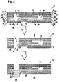
- FIG. 1 shows an analytical test element according to the invention in a sealed, opened and liquid sample applied state.
- the upper picture in FIG. 1 shows the test element 1 in the sealed state. It is made up of a variety of layers. On both outer sides it is sealed by a first and a second sealing layer (2 or 3), which have a low water vapor permeability.
- the first sealing layer 2 closes the sample receiving location 4 and has on its outer side a hydrophobic coating 5, so that an aqueous liquid sample does not wet the outside, but with opened seal at the sample receiving location 4 in the test element 1 arrived.
- a free space 6 is included, into which an inlet opening 7 and a vent opening 8 of a suitable for capillary transport of a liquid sample channel 9 open.
- the channel 9 is U-shaped and extends over several layers, namely two intermediate layers 10, 11 (first and second part of the channel 30, 31) and a carrier layer 12 (opening 32).
- the test element 1 also contains a transparent first carrier layer 13 and a third carrier layer 14 arranged adjacent to the second sealing layer 3.
- the carrier layers 12, 13, 14 form the cover and bottom layers of the channel 9.
- the second and third carrier layers 12, 14 each have on their, the channel 9 side facing a hydrophobic coating 15 and 16, which is intended to prevent the aqueous liquid sample thereof, in the Vent opening 8 facing part of the channel 9 to enter.
- a test field 17 is arranged on the side facing the transparent first carrier layer 13, on which the liquid sample can be analyzed.
- a detection window 18 in the first sealing layer 2 for the photometric analysis of the liquid sample on the test field 17.
- a desiccant In the channel 9 is further placed near the vent 8, a desiccant, the to absorb possible residual moisture in the sealed test element 1.
- the middle picture of the FIG. 1 shows an open test element 1, in which both sealing layers 2, 3 are pierced or cut open in the region of the free space 6.
- the sample receiving site 4 is now open and ready to receive a liquid sample.
- the inlet opening 7 of the channel 9 and the vent opening 8 of the channel 9 have also been simultaneously opened to the surroundings of the test element 1.
- the lower picture of the FIG. 1 shows how the liquid sample 20 reaches the test field 17.
- a sufficiently large drop of the liquid sample 20 is placed on the test element 1, from where the liquid sample 20 passes through the free space 6 to the inlet opening 7 of the channel 9 and is sucked into it by capillary forces.
- the sample 20 flows over the test field 17 where it is analyzed.
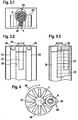
- FIG. 2 shows a further inventive analytical test element, the structure of which in FIG. 1 corresponds to the test element shown and additionally has a waste-type area 21, which can receive an excess 22 of liquid sample 20.
- FIG. 1 description given also on the test element 1 according to FIG. 2 to and the reference numbers have the same meaning as in FIG. 1 ,
- FIG. 3 schematically shows an inventive system for the analysis of liquid samples.
- FIG. 3 schematically shows a plan view of the system.
- the test elements 1 according to the invention are in the form of a magazine 23 in the form of a magazine.
- An expression cone serves as a compression unit 24 for increasing the pressure on the skin surrounding the body opening of a patient to deliver a body fluid such as blood or interstitial fluid from the body opening.
- the compression unit 24 is arranged above the sample receiving location 4 of a test element 1 located in the working position.
- FIG. 3 schematically shows a first side view of the same system according to the invention.
- the magazine in the form of a belt 23 passes over two transport rollers 25 in order to bring in each case a test element 1 in working position in which the compression unit 24 is located directly above the sample receiving location.
- a cylindrical piercing arrangement 26 (not visible) a piercing device and optionally a perforation device are arranged, which can be brought, for example, by turning a holder holding it one after the other in the working position, ie in a position in which the piercing device, the seal on both sides of the test element.
- the perforation device can produce a body opening in a placed on the compression unit 24 body part.
- a detector 27 for example for the photometric analysis of a sample, which is directed onto a (not shown) detection window in the test element 1 in the working position.
- FIG. 3 schematically shows a second side view of the same system according to the invention.
- the cylindrical arrangement 26, the detector 27, the band-shaped magazine 23 and the compression unit 24 are recognizable.
- FIG. 4 schematically shows another inventive system for analyzing liquid samples in a plan view.
- the system includes a magazine in the form of a diskette 28 on which the test elements 1 according to the invention are arranged radially on a substantially circular disk. By rotating the magazine 28 in the direction of rotation 29, in each case a test element 1 can be brought into the working position (sample receiving location 4 under the compression unit 24).
- the system further includes a piercing device (not shown) housed within a cylindrical assembly 26 and a detector 27.
Abstract
Description
Die vorliegende Erfindung betrifft ein analytisches Testelement, ein Testelementmagazin mit einer Vielzahl von analytischen Testelementen und ein System zur Analyse flüssiger Proben mit mindestens einem analytischen Testelement.The present invention relates to an analytical test element, a test element magazine having a plurality of analytical test elements, and a system for analyzing liquid samples having at least one analytical test element.
Zur Analyse von Proben, beispielsweise Körperflüssigkeiten wie Blut oder Urin, werden häufig Testelement-Analysesysteme verwendet, bei denen die zu analysierenden Proben auf ein Testelement gegeben werden und gegebenenfalls mit einer oder mehreren Reagenzien in einem Testfeld auf dem Testelement reagieren, bevor sie analysiert werden. Die optische, insbesondere photometrische Auswertung von Testelementen stellt eines der gebräuchlichsten Verfahren zur schnellen Bestimmung der Konzentration von Analyten in Proben dar. Photometrische Auswertungen werden allgemein im Bereich der Analytik, der Umweltanalytik und vor allem im Bereich der medizinischen Diagnostik eingesetzt. Insbesondere im Bereich der Blutglukosediagnostik aus Kapillarblut besitzen Testelemente, die photometrisch ausgewertet werden, einen großen Stellenwert.For analysis of samples such as body fluids such as blood or urine, test element analysis systems are often used in which the samples to be analyzed are placed on a test element and optionally reacted with one or more reagents in a test field on the test element before being analyzed. The optical, in particular photometric evaluation of test elements represents one of the most common methods for the rapid determination of the concentration of analytes in samples. Photometric evaluations are generally used in the field of analytics, environmental analysis and especially in the field of medical diagnostics. Particularly in the field of blood glucose diagnostics of capillary blood, test elements that are evaluated photometrically have a high priority.
In den letzten Jahren haben tragbare Messgeräte zur Blutzuckerbestimmung an Bedeutung gewonnen. Sie ermöglichen zu jeder Zeit mittels eines einfach zu bedienenden Messgerätes, einer hinsichtlich des Einstechschmerzes optimierten Stechhilfe und eines Testelements für den einmaligen Gebrauch, Blutzuckermesswerte zu bestimmen und damit eine genauere Insulindosierung des Patienten zur Stabilisierung seines Blutzuckerwertes vorzunehmen. Die Mehrzahl derzeit gebräuchlicher Blutzuckermessgeräte sieht getrennte Einzel-Testelemente, Messgeräte und Stechhilfen vor. Die Einzel-Testelemente werden hierbei von dem Patienten aus einer feuchtigkeitsgeschützten Einzelverpackung entnommen. Blut wird durch Einstich mit einer Stechhilfe gewonnen. Hierauf wird eine erforderliche Mindestmenge an Blut auf das Testelement aufgebracht und eine Messung mit Hilfe des Messgerätes durchgeführt.In recent years, portable gauges for blood glucose determination have gained in importance. They allow at any time by means of an easy-to-use measuring device, a puncture-optimized lancing device and a test element for single use, to determine blood glucose readings and thus make a more accurate insulin dosage of the patient to stabilize his blood sugar. The majority of currently used blood glucose meters provide separate individual test elements, measuring instruments and lancing devices. The individual test elements are in this case removed from the patient from a moisture-proof individual packaging. Blood is obtained by puncture with a lancing device. Then a required minimum amount of blood is applied to the test element and carried out a measurement using the meter.
Es gibt verschiedene Formen von Testelementen. Bekannt sind zum Beispiel im Wesentlichen quadratische Blättchen, die auch als Slides bezeichnet werden, in deren Mitte sich ein mehrschichtiges Testfeld befindet. Diagnostische Testelemente, die streifenförmig ausgebildet sind, werden als Teststreifen bezeichnet. Zur räumlichen Trennung von Detektionszone und Probenaufgabestelle eines Testelements sind im Stand der Technik kapillare Testelemente bekannt.There are different forms of test elements. For example, substantially square leaflets, also referred to as slides, are known in their middle multilayer test field is located. Diagnostic test elements that are strip-shaped are referred to as test strips. For the spatial separation of the detection zone and the sample application point of a test element, capillary test elements are known in the prior art.
In
Die Verpackung des jeweiligen Testelements ist so konzipiert, dass sie die wesentlichen Aufgaben zum Erhalt der Funktion der chemischen und biochemischen Bestandteile auf dem Testelement während einer längeren Lagerzeit erfüllt. Diese Aufgaben sind vor allem Schutz vor der Einwirkung von Lichtstrahlen, Schutz vor dem Zutritt von Feuchtigkeit, Schmutz, Keimen und Staub, sowie Schutz vor mechanischer Beeinträchtigung der Testelemente.The packaging of the respective test element is designed to perform the essential functions of maintaining the function of the chemical and biochemical constituents on the test element during a longer shelf life. These tasks are above all protection against the effects of light rays, protection against the ingress of moisture, dirt, germs and dust, as well as protection against mechanical impairment of the test elements.
Alternativ zu Einzelverpackungen sind Vorratsbehälter bekannt, welche eine Vielzahl von einzeln entnehmbaren Testelementen beinhalten und einen ausreichend großen Trockenmittelvorrat vorsehen, um die durch Öffnen und Entnahme eines Testelements eingeführte Feuchte zu absorbieren und somit eine ausreichende Lagerungszeit für alle im Behälter vorgesehenen Testelemente zu gewährleisten. Ein solcher Vorratsbehälter ist aus
Eine weitere anzutreffende Form eines Vorratsbehälters für Testelemente sind Aluminium- oder Kunststoffröhren, die von einem aufzudrückenden oder aufzuschraubenden Stopfen verschlossen sind. Diese Vorratsbehälter haben den Nachteil, dass die einzelnen Testelemente umständlich manuell entnommen werden müssen. Ein Patient, der zum Beispiel einen Blutzuckertest durchführen möchte, muss neben dem Messgerät eine Stechhilfe und einen getrennten Testelement-Vorratsbehälter mit sich führen. Neben dieser Unbequemlichkeit ist es vor allem nachteilig, dass bei Entnahme eines Testelements dieses und/oder ein anderes verunreinigt wird und die Verunreinigung zu falschen Messresultaten führen kann. Es besteht die Gefahr der Kontamination von Teststreifen durch an den Händen des Patienten haftenden Schmutz oder aufgrund des Herausfallens des Testelements.Another encountered form of reservoir for test elements are aluminum or plastic tubes, which are closed by a aufzudrückenden or screwed plug. These reservoirs have the disadvantage that the individual test elements must be removed manually cumbersome. For example, a patient who wants to perform a blood glucose test must carry a lancing device and a separate test element reservoir next to the meter. In addition to this inconvenience, it is especially disadvantageous that when removing a test element this and / or another is contaminated and the contamination can lead to false measurement results. There is a risk of contamination of test strips by dirt adhering to the patient's hands or due to the falling out of the test element.
Als Alternative ist die Lagerung einer bestimmten Anzahl an Testelementen im Messgerät selbst bekannt.As an alternative, the storage of a certain number of test elements in the meter itself is known.
Aus
Bei der Lagerung der Testelemente im Messgerät selbst wird durch einen Öffnungsmechanismus des Gerätes der Vorratsbehälter beziehungsweise die Kammer, in der sich ein Testelement befindet, geöffnet und das Testelement durch einen Bewegungsmechanismus in eine Probenaufnahmeposition gebrachtDuring storage of the test elements in the measuring device itself, the reservoir or the chamber in which a test element is located is opened by an opening mechanism of the device and the test element is brought into a sample receiving position by a movement mechanism
In
Nach der Aufnahme einer Probe (zum Beispiel Blut) auf das entnommene Testelement erfolgt die Detektion und Messdatenauswertung in dem Messgerät Nach der Entfernung des Testelements durch den Patienten oder einen weiteren, in das Gerät integrierten Mechanismus wird der Vorratsbehälter automatisch so positioniert, dass eine weitere Messung erfolgen kann.After receiving a sample (for example blood) on the removed test element, the detection and measurement data evaluation takes place in the measuring device. After removal of the test element by the patient or another mechanism integrated in the device, the reservoir is automatically positioned so that a further measurement can be done.
Der Schutz der Testelemente, insbesondere vor Eintreten der Feuchtigkeit, erfolgt im Stand der Technik üblicherweise durch Versiegelung des Vorratsbehälters beziehungsweise einzelner Kammern des Vorratsbehälters für die Testelemente. Die Versiegelung ist dabei zum Beispiel in Form eines geeigneten Folienmaterials geringer Wasserdampfdurchlässigkeit ausgeführt (beispielsweise mit adhäsivem Kunststoff beschichtete Aluminiumfolie). Ferner werden die Testelemente häufig durch Einbringen von Trockenmitteln in den Vorratsbehälter beziehungsweise in die Kammern vor Feuchtigkeit geschützt.The protection of the test elements, in particular before the occurrence of moisture, usually takes place in the prior art by sealing the reservoir or individual chambers of the reservoir for the test elements. The seal is carried out, for example, in the form of a suitable film material having a low water vapor permeability (for example, aluminum foil coated with adhesive plastic). Furthermore, the test elements are often protected by the introduction of desiccants in the reservoir or in the chambers from moisture.
Die im Stand der Technik bekannten Vorrichtungen, die die Bereitstellung der Testelemente, die Probenaufnahme- und die Messfunktion in dem Messgerät integrieren, haben den Nachteil, dass sie sehr komplex aufgebaut sind. Diese Komplexität ergibt sich insbesondere daraus, dass jeweils ein Testelement innerhalb der Vorrichtung zu verschiedenen Positionen transportiert werden muss (aus dem Vorratsbehälter zum Probenaufnahmeort, zur Messposition und dann zum Entsorgungsort). Ferner müssen die Testelemente im Stand der Technik aufwendig, insbesondere gegen Feuchtigkeit geschützt werden. Das Befüllen und Versiegeln des in die Vorrichtung integrierten, zur Lagerung der Testelemente dienenden Vorratsbehälters ist ein kosten- und zeitintensives Verfahren.Known in the prior art devices that integrate the provision of the test elements, the sample receiving and the measuring function in the meter, have the disadvantage that they are very complex. This complexity results in particular from the fact that in each case a test element within the device must be transported to different positions (from the reservoir to the sample receiving location, to the measuring position and then to the disposal site). Furthermore, the test elements in the prior art must be complicated, in particular protected against moisture. The filling and sealing of the integrated into the device, serving for storage of the test elements reservoir is a cost and time consuming process.
Aufgabe der vorliegenden Erfindung ist es daher, ein analytisches Testelement, ein Testelement-Magazin und ein System zur Analyse flüssiger Proben mit mindestens einem analytischen Testelement bereitzustellen, die die oben genannten Nachteile des Standes der Technik vermeiden. Insbesondere soll der Eintritt von Feuchtigkeit in die Testelemente vermieden werden. Dabei soll außerdem die Herstellung der Testelemente, des Testelement-Magazins und des Analysesystems vereinfacht und deren Komplexität verringert werden.It is therefore an object of the present invention to provide an analytical test element, a test element magazine and a system for analyzing liquid samples with at least one analytical test element, which avoid the above-mentioned disadvantages of the prior art. In particular, the entry of moisture into the test elements should be avoided. In addition, the manufacture of the test elements, the test element magazine and the analysis system is to be simplified and their complexity reduced.
Diese Aufgabe wird erfindungsgemäß gelöst durch ein analytisches Testelement zur Analyse einer flüssigen Probe, enthaltend einen zum kapillaren Transport der flüssigen Probe geeigneten Kanal mit einer Eintrittsöffnung für die flüssige Probe und einer Entlüftungsöffnung, wobei in dem Kanal, beabstandet zu der Eintrittsöffnung, mindestens ein Testfeld angeordnet ist, wobei das Testelement einen mit einer Versiegelung verschlossenen Probenaufnahmeort umfasst, der so ausgelegt ist, dass durch ein Öffnen der Versiegelung durch Durchstoßen oder Aufschneiden gleichzeitig der Probenaufnahmeort und die Eintrittsöffnung des Kanals zur Umgebung des Testelements hin öffenbar ist und die flüssige Probe durch das Testelement über den Probenaufnahmeort und die Eintrittsöffnung in den Kanal zur Analyse in dem Testfeld aufnehmbar ist.This object is achieved according to the invention by an analytical test element for analyzing a liquid sample, comprising a channel suitable for capillary transport of the liquid sample with an inlet for the liquid sample and a vent opening, wherein at least one test field is arranged in the channel, spaced from the inlet opening wherein the test element comprises a sealed sample receiving location designed so that by opening the seal by piercing or cutting, the sample receiving site and the inlet opening of the channel can be simultaneously opened to the environment of the test element and the liquid sample through the test element can be received in the test field via the sample receiving location and the inlet opening into the channel for analysis.
Das erfindungsgemäße Testelement hat den Vorteil, dass das Testelement selbst weitgehend wasserdampfundurchlässig und schmutzabweisend durch die Versiegelung verschlossen ist und somit für den Zeitraum der Benutzung im Gerät keine getrennte Aufbewahrungsmöglichkeit zum Schutz vor eintretender Feuchtigkeit oder Verunreinigung benötigt. Der eine Messung vorbereitende Schritt des Auspackens eines Testelements kann somit entfallen, wodurch sich eine vereinfachte Handhabung für den Benutzer beziehungsweise ein einfacherer Aufbau eines Messgeräts, in das die Testelemente bereits integriert sind, ergibt. Durch das Öffnen der Versiegelung am Probenaufnahmeort werden auch die Eintrittsöffnung des Kanals geöffnet, so dass das Testelement mit einem einzigen Öffnungsvorgang einsatzbereit ist. Der zum kapillaren Transport der flüssigen Probe geeignete Kanal mit integriertem Testfeld hat den Vorteil, dass durch die Kapillarkräfte ein automatischer Transport der flüssigen Probe zum Testelement, das den Detektionsbereich darstellt, erfolgt. Die zu analysierende Probe kann direkt auf den Probenaufnahmeort gegeben werden.The test element according to the invention has the advantage that the test element itself is largely impermeable to water vapor and dirt-repellent closed by the seal and thus for the period of use in the device no separate storage option for protection against entering moisture or contamination needed. The preparatory step of unpacking a test element can thus be dispensed with, which results in a simplified handling for the user or a simpler design of a measuring device in which the test elements are already integrated. By opening the seal at the sample receiving location, the inlet opening of the channel is opened, so that the test element is ready for use with a single opening operation. The channel with integrated test field which is suitable for the capillary transport of the liquid sample has the advantage that the capillary forces cause an automatic transport of the liquid sample to the test element, which represents the detection area. he follows. The sample to be analyzed can be added directly to the sample receiving site.
Die Entlüftungsöffnung stellt eine Entlüftung des Kanals bei dem kapillaren Transport der flüssigen Probe über die Eintrittsöffnung in dem Kanal zum Testfeld sicher. Sie kann bei dem erfindungsgemäßen Testelement bereits vor dem Öffnen der Versiegelung zur Umgebung des Testelements offen sein. Dabei kann eine Kontamination des Testfeldes über die Entlüftungsöffnung durch eine geeignete Führung des Kanals vermieden werden. In einer anderen Ausführungsform der vorliegenden Erfindung mündet die Entlüftungsöffnung in einen ausreichend großen, zur Umgebung des Testelements hin abgeschlossenen Hohlraum, der eine Entlüftung des Kanals über die Entlüftungsöffnung ohne eine Öffnung des Hohlraums zur Umgebung hin erlaubt. Es ist ferner möglich, dass die Entlüftungsöffnung separat versiegelt ist und durch ein Öffnen dieser separaten Versiegelung zur Umgebung des Testelements hin geöffnet wird. In einer bevorzugten Ausführungsform der vorliegenden Erfindung werden durch ein Öffnen nur einer Versiegelung gleichzeitig der Probenaufnahmeort, die Eintrittsöffnung des Kanals und die Entlüftungsöffnung des Kanals zur Umgebung des Testelements hin geöffnetThe vent ensures venting of the channel in the capillary transport of the liquid sample via the inlet opening in the channel to the test field. In the case of the test element according to the invention, it can already be open to the surroundings of the test element before the seal is opened. In this case, a contamination of the test field via the vent opening can be avoided by a suitable guidance of the channel. In another embodiment of the present invention, the vent opening opens into a sufficiently large, closed to the environment of the test element cavity, which allows venting of the channel via the vent opening without an opening of the cavity to the environment. It is also possible that the vent opening is sealed separately and opened by opening this separate seal towards the environment of the test element. In a preferred embodiment of the present invention, by opening only one seal, the sample receiving location, the inlet opening of the channel and the vent opening of the channel are opened to the surroundings of the test element at the same time
Das Testfeld ist in dem Kanal vorzugsweise zwischen der Eintrittsöffnung und der Entlüftungsöffnung angeordnet. In einer bevorzugten Ausführungsform der vorliegenden Erfindung ist die Eintrittsöffnung an einem Ende des Kanals und die Entlüftungsöffnung am anderen Ende des Kanals angeordnet. Die flüssige Probe tritt durch die Eintrittsöffnung in den Kanal ein und füllt diesen zumindest bis das Testfeld benetzt wird, woraufhin bevorzugt ein oder mehrere Bestandteile der flüssigen Probe auf photometrischem oder elektrochemischem Wege analysiert werden. Ferner ist eine homogene Benetzung des Testfeldes mit einer durch den Kanaldurchmesser vorgegebenen Menge an Probe sichergestellt, wodurch die Präzision und Reproduzierbarkeit der Messung erhöht wird. Ein weiterer Vorteil des erfindungsgemäßen Testelementes ist, dass das Testfeld beim Öffnen (durch Stoßen, Aufschneiden, Abziehen) nicht beschädigt und durch abfallende Versiegelungsreste verunreinigt wird.The test field is preferably arranged in the channel between the inlet opening and the vent opening. In a preferred embodiment of the present invention, the inlet opening is arranged at one end of the channel and the vent opening at the other end of the channel. The liquid sample enters the channel through the inlet opening and fills it at least until the test field is wetted, after which preferably one or more constituents of the liquid sample are analyzed by photometric or electrochemical means. Furthermore, a homogeneous wetting of the test field is ensured with a predetermined amount of sample by the channel diameter, whereby the precision and reproducibility of the measurement is increased. A further advantage of the test element according to the invention is that the test field is not damaged during opening (by pushing, cutting, peeling) and is contaminated by falling sealing residues.
Die Versiegelung sollte bei dem erfindungsgemäßen Testelement aus einem weitgehend wasserdampfundurchlässigen Material bestehen, beispielsweise aus einer mit einem Polymer beschichteten Alufolie.In the case of the test element according to the invention, the seal should consist of a largely water vapor-impermeable material, for example of a polymer film coated with aluminum foil.
Erfindungsgemäß münden die Eintrittsöffnung und ggf. auch die Entlüftungsöffnung des Kanals in einen Freiraum in dem Testelement, der so angeordnet ist, dass er beim Öffnen der Versiegelung zur Umgebung des Testelements hin geöffnet wird. Vorzugsweise wird der Freiraum im unbenutzten Zustand des Testelements an einer ersten Seite zumindest teilweise durch die den Probenaufnahmeort verschließende Versiegelung und an einer der ersten Seite gegenüberliegenden zweiten Seite zumindest teilweise durch eine zweite Versiegelung begrenzt. Diese Anordnung hat den Vorteil, dass eine Durchstoßvorrichtung (zum Beispiel Lanzette, Nadel, Messer, Kanüle, Dorn) zunächst die zweite Versiegelung auf der dem Probenaufnahmeort gegenüberliegende Seite öffnen kann und anschließend durch den Freiraum hindurch auch die Versiegelung des Probenaufnahmeortes. Dies ermöglicht eine vereinfachte Konstruktion eines integrierten Messsystems, da der Aufnahmeort der flüssigen Probe und die Durchstoßvorrichtung auf gegenüberliegenden Seiten des Testelements angeordnet werden können und die Durchstoßvorrichtung der Probenaufnahme so nicht im Wege steht. Ferner kann die Durchstoßvorrichtung auch als Perforationsvorrichtung dienen, die außer dem Öffnen der beiden Versiegelungen auch das Perforieren der Haut eines Patienten zur Probenentnahme ausführt, so dass daraufhin aus dem Perforationsort der Haut austretende Körperflüssigkeit direkt als flüssige Probe in das Testelement eintreten kann. Der Patient muss dazu keine weiteren Handhabungsschritte oder Bewegungen durchführen und benötigt auch keine zusätzlichen Geräte.According to the invention, the inlet opening and optionally also the vent opening of the channel open into a free space in the test element, which is arranged so that it is opened when opening the seal to the environment of the test element. Preferably, in the unused state of the test element, the free space on a first side is at least partially bounded by the seal closing the sample receiving location and at least partially by a second seal on a second side opposite the first side. This arrangement has the advantage that a piercing device (for example lancet, needle, knife, cannula, mandrel) can first open the second seal on the side opposite the sample receiving site and subsequently also seal the sample receiving site through the free space. This allows a simplified construction of an integrated measuring system, since the location of the liquid sample and the piercing device can be arranged on opposite sides of the test element and thus the sample receiving piercing device does not get in the way. Furthermore, the puncture device can also serve as a perforation device which, in addition to the opening of the two seals, also perforates the skin of a patient for sampling, so that body fluid emerging from the perforation site of the skin can then enter the test element directly as a liquid sample. The patient does not have to perform any further handling steps or movements and does not need any additional devices.
In einer bevorzugten Ausführungsform der vorliegenden Erfindung verläuft der Kanal in dem Testelement u-förmig oder v-förmig. Dieser Verlauf hat den Vorteil einer Platz sparenden Unterbringung des Kanals in dem Testelement. Die Kanalenden können dabei in einem in dem Testelement enthaltenen Freiraum übereinander oder nebeneinander angeordnet sein.In a preferred embodiment of the present invention, the channel in the test element is U-shaped or V-shaped. This course has the advantage of a space-saving housing of the channel in the test element. The channel ends can be arranged one above the other or side by side in a free space contained in the test element.
Da für den bevorzugten Fall, dass der Kanal einen im Wesentlichen rechteckigen Querschnitt aufweist, eine Dimension, beispielsweise die Höhe des Kanals, durch die physikalischen Grenzen der Kapillaraktivität vorgegeben ist, lässt sich das Volumen des kapillaren Kanals durch geeignete Wahl der beiden übrigen Dimensionen, beispielsweise Länge und Breite, einstellen. Die Höhe liegt bevorzugt für wässrige flüssige Proben bei weniger als 1 mm, besonders bevorzugt bei weniger als 0,5 mm. Die Breite des Kanals kann bevorzugt weniger als 5 mm, besonders bevorzugt weniger als 2 mm und die Gesamtlänge des Kanals bevorzugt weniger als 5 cm, besonders bevorzugt weniger als 2 cm betragen.Since, for the preferred case that the channel has a substantially rectangular cross-section, one dimension, for example the height of the channel, is dictated by the physical limits of capillary activity, the volume of the capillary channel can be selected by suitable choice of the other two dimensions, for example Length and width, adjust. The height is preferably less than 1 mm for aqueous liquid samples, more preferably less than 0.5 mm. The width of the channel may preferably be less than 5 mm, more preferably less than 2 mm and the total length of the channel preferably less than 5 cm, more preferably less than 2 cm.
In einer bevorzugten Ausführungsform der vorliegenden Erfindung ist der Abstand des Probenaufnahmeortes zur Eintrittsöffnung des Kanals geringer als der Abstand des Probenaufnahmeortes zur Entlüftungsöffnung des Kanals. Dies hat den Vorteil, dass die am Probenaufnahmeort in das Testelement eintretende flüssige Probe in die Eintrittsöffnung und nicht in die Entlüftungsöffnung des Kanals eintritt, da die Entlüftungsöffnung frei von Probenflüssigkeit bleiben soll, um ein Entweichen von Luft beim Befüllen des Kanals zu ermöglichen.In a preferred embodiment of the present invention, the distance of the sample receiving location to the inlet opening of the channel is less than the distance of the sample receiving location to the vent opening of the channel. This has the advantage that the liquid sample entering the test element at the sample receiving location enters the inlet opening and not the vent opening of the channel, since the vent opening should remain free of sample liquid in order to allow air to escape during filling of the channel.
Vorzugsweise weist der Kanal im Bereich der Eintrittsöffnung eine bessere Benetzbarkeit durch die flüssige Probe auf als im Bereich der Entlüftungsöffnung. Durch diese Maßnahme soll ebenfalls ein Eintreten der flüssigen Probe in die Eintrittsöffnung des Kanals gefördert und in die Entlüflungsöffnung verhindert werden. Vorzugsweise weist außerdem der Kanal in seinem Inneren zwischen der Eintrittsöffnung und dem mindestens einen Testfeld eine bessere Benetzbarkeit durch die flüssige Probe auf, als zwischen dem mindestens einen Testfeld und der Entlüftungsöffnung. Dies kann durch eine Hydrophobierung der Entlüftungsöffnung und/oder sich daran anschließender, nicht zu benetzender Abschnitte des Kanals bewerkstelligt werden.Preferably, the channel in the region of the inlet opening has a better wettability by the liquid sample than in the region of the vent opening. By this measure, also an entry of the liquid sample is to be promoted in the inlet opening of the channel and prevented in the Entlüflungsöffnung. Preferably, moreover, the channel has better wettability by the liquid sample in its interior between the inlet opening and the at least one test field than between the at least one test field and the vent opening. This can be accomplished by hydrophobing the vent and / or adjoining non-wettable portions of the channel.
In einer bevorzugten Ausführungsform der vorliegenden Erfindung weist die den Probenaufnahmeort verschließende Versiegelung auf der der Innenseite des Testelements zugewandten Seite eine bessere Benetzbarkeit durch die flüssige Probe auf, als auf der der Innenseite des Testelements abgewandten Seite. Dies hat den Vorteil, dass beim direkten Aufbringen der flüssigen Probe auf die durchstoßene Versiegelung am Probenaufnahmeort die Außenseite der Versiegelung durch die Probe schlecht benetzt wird. Somit wird ein Transport der Probe zur besser zu benetzenden Innenseite der Versiegelung hin, und folglich der gewünschte Transport in das Testelement hinein gefordert.In a preferred embodiment of the present invention, the seal closing off the sample receiving location on the side facing the inside of the test element has better wettability by the liquid sample than on the side facing away from the inside of the test element. This has the advantage that when the liquid sample is applied directly to the pierced seal at the sample receiving site, the outside of the seal through the sample is poorly wetted. Thus, a transport of the sample towards the better wetted inside of the seal is required, and consequently the desired transport into the test element is required.
In einer bevorzugten Ausführungsform der vorliegenden Erfindung ist in dem Testelement ein Trockenmittel enthalten. Dieses Trockenmittel kann den Schutz des Testelements vor eintretender Feuchtigkeit noch erhöhen, da es Feuchtigkeit adsorbiert. Das Trockenmittel kann beispielsweise in dem Kanal in der Nähe der Entlüftungsöffnung enthalten sein. Als Trockenmittel können zum Beispiel feste Trockenmittel verwendet werden. Vorzugsweise enthält das Trockenmittel Zeolithe oder Silikagel. Es sind Zeolithe oder Silikagel in Form von beads oder Tabletten, aber auch filmartig aufbringbare Schmelzkleber mit Silikagel oder Zeolithfüllung, wie sie in der Verpackungsindustrie zum Einsatz kommen, einsetzbar.In a preferred embodiment of the present invention, a desiccant is contained in the test element. This desiccant may increase the protection of the test element from moisture ingress by adsorbing moisture. For example, the desiccant may be contained in the channel near the vent. As desiccant, for example, solid desiccants can be used. Preferably, the desiccant contains zeolites or silica gel. There are zeolites or silica gel in the form of beads or tablets, but also applicable film-like hot melt adhesive with silica gel or zeolite, as used in the packaging industry, can be used.
In einer bevorzugten Ausführungsform der vorliegenden Erfindung enthält das Testelement einen Waste-Bereich zur Aufnahme eines Überschusses an flüssiger Probe in dem Testelement. Der Waste-Bereich dient dazu, ein unerwünschtes Befüllen bestimmter Bereiche des Testelements, insbesondere des Kanals im Bereich der Entlüftungsöffnung, mit flüssiger Probe zu vermeiden.In a preferred embodiment of the present invention, the test element includes a waste area for receiving an excess of liquid sample in the test element. The waste area is used to avoid unwanted filling of certain areas of the test element, in particular of the channel in the region of the vent, with liquid sample.
Vorzugsweise weist die den Probenaufnahmeort verschließende Versiegelung eine Vorstrukturierung auf, die so gestaltet ist, dass beim Öffnen der Versiegelung ein definierter Grat entsteht. Der definierte Grat oder Auswurf soll dabei klare Kanten aufweisen, die einen Transport der flüssigen Probe in das Testelement hinein erleichtern. Durch die definierte Geometrie und Dimension des Grates oder Auswurfs wird erreicht, dass die flüssige Probe mit erhöhter Wahrscheinlichkeit mit dem kapillaraktiven Kanal in Kontakt kommt und in das Innere des Kanals eingesaugt wird. Eine mögliche Vorstrukturierung ist dabei kreuz- oder sternförmig, wobei ein umhüllendes Rechteck oder ein umhüllender Kreis zur Definition der Länge des Auswurfs hinzugefügt werden kann.Preferably, the seal closing off the sample receiving location has a pre-structuring which is designed in such a way that a defined burr is produced when the seal is opened. The defined burr or ejection should have clear edges that facilitate transport of the liquid sample into the test element. The defined geometry and dimension of the ridge or ejection ensures that the liquid sample is more likely to come into contact with the capillary-active channel and be sucked into the interior of the channel. A possible pre-structuring is cross-shaped or star-shaped, wherein an enveloping rectangle or an enveloping circle can be added to define the length of the ejection.
In einer bevorzugten Ausführungsform der vorliegenden Erfindung enthält das Testelement ein dem Testfeld zugewandtes Detektionsfenster zur photometrischen Analyse der flüssigen Probe auf dem Testfeld. Durch das Detektionsfenster, das im relevanten Wellenlängenbereich transparent ist, kann sowohl von einer Lichtquelle ausgesandtes Licht, als auch vom Testfeld reflektiertes Licht hindurchtreten. Ein Detektor kann so das reflektierte Licht detektieren, wobei die detektierten Signale durch eine Elektronik verarbeitet und das Ergebnis einem Benutzer auf einer Anzeigevorrichtung dargestellt werden können.In a preferred embodiment of the present invention, the test element contains a detection window facing the test field for the photometric analysis of the liquid sample on the test field. The detection window, which is transparent in the relevant wavelength range, allows both light emitted by a light source and light reflected by the test field to pass through. A detector may thus detect the reflected light, the detected signals being processed by electronics and the result displayed to a user on a display device.
In einer bevorzugten Ausführungsform der vorliegenden Erfindung sind in mindestens einer den Kanal begrenzenden Wand Leiterbahnen für eine elektrochemische Analyse der flüssigen Probe auf dem Testfeld eingebracht. Diese Leiterbahnen werden für eine elektrochemische Analyse der flüssigen Probe im Testfeld des Testelements benötigt. Es ist auch eine gleichzeitige photometrische und elektrochemische Analyse denkbar.In a preferred embodiment of the present invention, conductor tracks for an electrochemical analysis of the liquid sample are introduced into the test field in at least one channel delimiting the channel. These traces are needed for electrochemical analysis of the liquid sample in the test field of the test element. It is also conceivable a simultaneous photometric and electrochemical analysis.
In einer bevorzugten Ausführungsform der vorliegenden Erfindung ist das Testelement aus einer Vielzahl von Schichten aufgebaut Dies hat den Vorteil einer vereinfachten Herstellung. Die verschiedenen Eigenschaften, wie zum Beispiel die Benetzbarkeit, optische Transparenz, Stabilität und Form, verschiedene Bereiche des Testelements können durch die entsprechende Gestaltung der einzelnen Schichten erreicht werden, die miteinander verbunden werden.In a preferred embodiment of the present invention, the test element is composed of a plurality of layers. This has the advantage of simplified fabrication. The various properties, such as wettability, optical transparency, stability and shape, different areas of the test element can be achieved by the appropriate design of the individual layers that are joined together.
Der Kanal kann bei dem schichtweise aufgebauten Testelement durch eine oder mehrere Schichten verlaufen. Der gesamte Kanal oder Teilbereiche des Kanals können durch Ausschneiden oder Ausstanzen eines Teils einer oder mehrerer Schichten hergestellt werden. Ein u- oder v-förmiger Kanal wird folglich durch Ausstanzen oder Ausschneiden eines u- oder v-förmigen Bereichs aus einer einzigen Zwischenschicht oder entsprechend geformter Bereiche aus mehreren, anschließend aufeinander gestapelten Schichten hergestellt (zum Beispiel zwei rechteckige Bereiche in zwei Zwischenschichten, zwischen denen eine Trägerschicht angeordnet wird, die die beiden rechteckigen Kanalabschnitte über eine Öffnung verbindet). Die Kanalhöhe wird dabei durch die Dicke der Zwischenschicht festgelegt. Ein Freiraum in dem Testelement kann ebenfalls durch Ausschneiden oder Ausstanzen von Bereichen der entsprechenden Form in einer oder mehreren Schichten erzeugt werden.The channel may pass through one or more layers in the layered test element. The entire channel or portions of the channel can be made by cutting or punching a portion of one or more layers. Thus, a u- or v-shaped channel is made by punching or cutting out a u- or v-shaped region from a single interlayer or correspondingly shaped regions of multiple, then stacked layers (eg, two rectangular regions in two interlayers between which a carrier layer is arranged which connects the two rectangular channel sections via an opening). The channel height is determined by the thickness of the intermediate layer. A clearance in the test element can also be created by cutting or punching out regions of the corresponding shape in one or more layers.
Das schichtweise aufgebaute erfindungsgemäße analytische Testelement umfasst mindestens eine Versiegelungsschicht. Eine erste Versiegelungsschicht dient als Versiegelung des Probenaufnahmeortes (mit oben beschriebenen Eigenschaften), die zur Verwendung des Testelements mittels Durchstoßen oder Aufschneiden (vorzugsweise mittels Durchstoßen) geöffnet wird. Weitere Versiegelungsschichten können beispielsweise auf der der ersten Versiegelungsschicht entgegengesetzten Seite des Testelements oder auf seinen in einem Winkel von 90° dazu angeordneten Seitenflächen zum Schutz des Testelements vor Feuchtigkeit und Verunreinigung dienen und gegebenenfalls teilweise zusätzlich zu der ersten Versiegelungsschicht bei der Verwendung des Testelements geöffnet werden.The layered inventive analytical test element comprises at least one sealing layer. A first sealing layer serves as a seal of the sample receiving site (with properties described above) which is opened by means of puncturing or cutting (preferably by piercing) for use of the test element. Additional sealant layers may serve, for example, on the side of the test element opposite the first sealant layer or on its side surfaces disposed at 90 ° thereto to protect the test element from moisture and contamination, and optionally partially opened in addition to the first sealant layer when using the test element.
In einer bevorzugten Ausführungsform der vorliegenden Erfindung weist die Versiegelungsschicht eine hydrophobe Beschichtung auf. Die erste Versiegelungsschicht hat vorzugsweise eine hydrophobe Beschichtung auf ihrer Außenseite, um die oben beschriebene bessere Benetzbarkeit durch die wässrige flüssige Probe auf ihrer Innenseite gegenüber ihrer Außenseite zu erreichen.In a preferred embodiment of the present invention, the sealing layer has a hydrophobic coating. The first sealing layer preferably has a hydrophobic coating on its outside to achieve the above-described better wettability by the aqueous liquid sample on its inside from its outside.
Vorzugsweise umfasst das schichtweise aufgebaute erfindungsgemäße Testelement mindestens eine Trägerschicht und mindestens eine, den Kanal zumindest teilweise enthaltende Zwischenschicht. Die Trägerschichten geben dem Testelement Stabilität. Sie können zum Beispiel den Kanal als Boden- und Deckschichten begrenzen und das Testfeld umfassen. Diese Boden- und Deckschichten können in ausgewählten Bereichen (vorzugsweise zwischen Eintrittsöffnung und Testfeld) hydrophile Materialien enthalten und/oder hydrophilierte Oberflächen aufweisen. Hydrophile Oberflächen sind in diesem Zusammenhang Wasser anziehende Flächen. Wässrige Proben, darunter auch Blut, spreiten auf solchen Oberflächen gut. Sie weisen eine gute Benetzbarkeit durch diese Proben auf. Solche Flächen sind u.a. dadurch charakterisiert, dass an der Grenzfläche ein Wassertropfen auf ihnen einen spitzen Rand- oder Kontaktwinkel ausbildet. Im Gegensatz dazu wird hydrophoben, d.h. Wasser abweisenden Oberflächen, an der Grenzfläche zwischen Wassertropfen und Oberfläche ein stumpfer Randwinkel ausgebildet.The layered test element according to the invention preferably comprises at least one carrier layer and at least one intermediate layer at least partially containing the channel. The carrier layers give the test element stability. For example, you can limit the channel as ground and top layers and include the test field. These floor and cover layers may be in selected areas (preferably between inlet and test field) contain hydrophilic materials and / or have hydrophilic surfaces. Hydrophilic surfaces are water-attracting surfaces in this context. Aqueous samples, including blood, spread well on such surfaces. They have good wettability by these samples. Such surfaces are characterized, inter alia, by the fact that at the interface a drop of water forms a pointed edge or contact angle on them. In contrast, hydrophobic, ie water-repellent surfaces, formed at the interface between water droplets and surface a dull edge angle.
Der Randwinkel als Resultat der Oberflächenspannungen der Prüfflüssigkeit und der zu untersuchenden Oberfläche ist als Maß für die Hydrophilie einer Oberfläche geeignet. Wasser hat beispielsweise eine Oberflächenspannung von 72 mN/m. Liegt der Wert der Oberflächenspannung der betrachteten Fläche weit, d.h. mehr als 20 mN/m unter diesem Wert, so ist die Benetzung schlecht und der resultierende Randwinkel ist stumpf. Eine solche Fläche wird als hydrophob bezeichnet. Nähert sich die Oberflächenspannung dem Wert, der für Wasser gefunden wird, so ist die Benetzung gut und der Randwinkel wird spitz. Wird die Oberflächenspannung dagegen gleich oder größer dem für Wasser gefundenen Wert, so zerläuft der Tropfen und es findet Totalspreitung der Flüssigkeit statt. Ein Randwinkel ist dann nicht mehr zu messen. Flächen, die mit Wassertropfen einen spitzen Randwinkel bilden oder bei denen Totalspreitung eines Wassertropfens beobachtet wird, werden als hydrophil bezeichnet.The contact angle as a result of the surface tensions of the test liquid and the surface to be examined is suitable as a measure of the hydrophilicity of a surface. For example, water has a surface tension of 72 mN / m. If the value of the surface tension of the surface under consideration is wide, i. more than 20 mN / m below this value, the wetting is poor and the resulting contact angle is dull. Such a surface is called hydrophobic. When the surface tension approaches the value found for water, the wetting is good and the contact angle becomes acute. On the other hand, if the surface tension becomes equal to or greater than the value found for water, the droplet will segregate and the liquid will expand. A contact angle is then no longer measurable. Surfaces that form a sharp contact angle with water droplets or in which total spread of a drop of water is observed are referred to as hydrophilic.
Die Bereitschaft einer Kapillare, eine Flüssigkeit aufzusaugen, geht mit der Benetzbarkeit der Kanaloberfläche mit der Flüssigkeit einher. Für wässrige Proben bedeutet dies, dass eine Kapillare aus einem Material gefertigt werden sollte, dessen Oberflächenspannung nahe an 72 mN/m heranreicht oder diesen Wert übertrifft.The readiness of a capillary to absorb a liquid is associated with the wettability of the channel surface with the liquid. For aqueous samples, this means that a capillary should be made of a material whose surface tension approaches or exceeds 72 mN / m.
Ausreichend hydrophile Materialien zum Aufbau einer Kapillare, die schnell wässrige Proben aufsaugt, sind beispielsweise Glas, Metall oder Keramik. Für den Einsatz in Testelementen sind diese Materialien jedoch nicht so gut geeignet, da sie einige Nachteile aufweisen, beispielsweise Bruchgefahr bei Glas oder Keramik oder Veränderung der Oberflächeneigenschaften mit der Zeit bei zahlreichen Metallen. Üblicherweise werden deshalb zur Fertigung von Testelementen Kunststofffolien oder -formteil eingesetzt. Die verwendeten Kunststoffe übertreffen dabei in der Regel kaum eine Oberflächenspannung von 45 mN/m. Selbst mit den, relativ betrachtet, hydrophilsten Kunststoffen, wie beispielsweise Polymethylmethacrylat (PMMA) oder Polyamid (PA) lassen sich - wenn überhaupt - nur sehr langsam saugende Kapillaren aufbauen. Kapillaren aus unbehandelten hydrophoben Kunststoffen, wie beispielsweise Polystyrol (PS), Polypropylen (PP) oder Polyethylen (PE) saugen im Wesentlichen keine wässrigen Proben. Hieraus ergibt sich die Notwendigkeit, Kunststoffe für die Verwendung als Konstruktionsmaterial für Testelemente mit kapillaraktiven Kanälen hydrophil auszustatten, d.h. zu hydrophilieren.Sufficiently hydrophilic materials for building up a capillary which quickly absorbs aqueous samples are, for example, glass, metal or ceramic. For use in test elements, however, these materials are not so well suited because they have some disadvantages, such as risk of breakage in glass or ceramic or change in surface properties over time in many metals. Usually therefore plastic films or molded part are used for the production of test elements. As a rule, the plastics used hardly exceed a surface tension of 45 mN / m. Even with the, relatively speaking, most hydrophilic plastics, such as polymethyl methacrylate (PMMA) or polyamide (PA) can be - if at all - only Build up very slowly sucking capillaries. Capillaries made of untreated hydrophobic plastics, such as polystyrene (PS), polypropylene (PP) or polyethylene (PE) suck substantially no aqueous samples. This results in the need to provide hydrophilic, ie to hydrophilize, plastics for use as construction material for test elements with capillary-active channels.
In einer bevorzugten Ausführungsform des erfindungsgemäßen analytischen Testelements ist zumindest eine, besser jedoch zwei, ganz besonders bevorzugt zwei sich gegenüberliegende Flächen der die innere Oberfläche des zum kapillaren Flüssigkeitstransports befähigten Kanals bildenden Flächen, hydrophiliert. Wird mehr als eine Fläche hydrophiliert, so können die Flächen entweder mit der gleichen oder mit unterschiedlichen Methoden hydrophil gemacht werden. Die Hydrophilierung ist vor allem dann notwendig, wenn die Materialien, die den kapillaraktiven Kanal bilden, insbesondere die Trägerschichten, selbst hydrophob oder nur wenig hydrophil sind, beispielsweise weil sie aus unpolaren Kunststoffen bestehen.In a preferred embodiment of the analytical test element according to the invention, at least one, but more preferably two, most preferably two opposing surfaces of the surfaces forming the inner surface of the channel capable of capillary liquid transport are hydrophilized. If more than one surface is hydrophilized, then the surfaces can be made hydrophilic either by the same or by different methods. Hydrophilization is necessary above all when the materials which form the capillary-active channel, in particular the carrier layers, are themselves hydrophobic or only slightly hydrophilic, for example because they consist of nonpolar plastics.
Idealerweise wird die Hydrophilierung der Oberfläche des kapillaren Kanals dadurch erreicht, dass zu seiner Fertigung, insbesondere zur Fertigung der Trägerschichten, ein hydrophiles Material eingesetzt wird, das jedoch die Probenflüssigkeit selbst nicht oder nicht wesentlich aufzusaugen vermag. Wo dies nicht möglich ist, kann die Hydrophilierung einer hydrophoben oder nur sehr wenig hydrophilen Oberfläche durch geeignete Beschichtung mit einer stabilen, gegenüber dem Probenmaterial inerten, hydrophilen Schicht erreicht werden, beispielsweise durch kovalente Bindung von photoreaktiv ausgerüsteten, hydrophilen Polymeren auf eine Kunststoffoberfläche, durch Aufbringen netzmittelhaltiger Schichten oder durch Beschichtung von Oberflächen mit Nanokompositen mittels Sol-Gel-Technologie. Darüber hinaus ist es möglich, durch thermische, physikalische oder chemische Behandlung der Oberfläche eine gesteigerte Hydrophilie zu erzielen.Ideally, the hydrophilization of the surface of the capillary channel is achieved by using a hydrophilic material for its production, in particular for the production of the carrier layers, which, however, is unable or not substantially to absorb the sample liquid itself. Where this is not possible, the hydrophilization of a hydrophobic or only slightly hydrophilic surface can be achieved by suitable coating with a stable hydrophilic layer inert to the sample material, for example by covalent bonding of photoreactively-treated hydrophilic polymers to a plastic surface by application wetting agent-containing layers or by coating surfaces with nanocomposites by means of sol-gel technology. In addition, it is possible to achieve increased hydrophilicity by thermal, physical or chemical treatment of the surface.
Ganz besonders bevorzugt wird die Hydrophilierung durch die Verwendung von dünnen Schichten oxidierten Aluminiums erreicht. Diese Schichten werden entweder direkt auf die gewünschten Bauteile des Testelements aufgebracht, beispielsweise durch Vakuumbedampfen der Werkstücke mit metallischem Aluminium und anschließender Oxidation des Metalls, oder in Form von Metallfolien oder metallbeschichteten Kunststofffolien für den Testelement-Aufbau verwendet, die ebenfalls zur Erzielung der erwünschten Hydrophilie oxidiert werden müssen. Metallschichtdicken von 1 bis 500 nm sind dabei ausreichend. Die Metallschicht wird anschließend zur Bildung der oxidierten Form oxidiert, wobei sich neben der elektrochemischen, anodischen Oxidation vor allem die Oxidation in Gegenwart von Wasserdampf oder durch Kochen in Wasser als besonders geeignete Methoden herausgestellt haben. Die so erzielten Oxidschichten sind je nach Methode zwischen 0,1 und 500 nm, bevorzugt zwischen 10 und 100 nm dick. Größere Schichtdicken sowohl der Metallschicht als auch der Oxidschicht sind ebenfalls praktisch realisierbar.Most preferably, the hydrophilization is achieved by the use of thin layers of oxidized aluminum. These layers are either applied directly to the desired components of the test element, for example by vacuum evaporation of the workpieces with metallic aluminum and subsequent oxidation of the metal, or in the form of metal foils or metal-coated plastic films for the test element structure, which also oxidizes to achieve the desired hydrophilicity Need to become. Metal layer thicknesses of 1 to 500 nm are sufficient. The metal layer is then oxidized to form the oxidized form, wherein In addition to the electrochemical, anodic oxidation, especially the oxidation in the presence of water vapor or by boiling in water have been found to be particularly suitable methods. Depending on the method, the oxide layers obtained in this way are between 0.1 and 500 nm, preferably between 10 and 100 nm thick. Larger layer thicknesses of both the metal layer and the oxide layer are also practically feasible.
Die als Boden- und Deckschichten des Kanals dienenden Trägerschichten können außerdem in ausgewählten Bereichen (vorzugsweise zwischen Entlüftungsöffnung und Testfeld) hydrophobe Materialien aufweisen oder eine hydrophobe Oberflächenbeschichtung besitzen. Diese soll für eine schlechte Benetzbarkeit der Trägerschichtoberfläche durch wässrige flüssige Proben sorgen, um zum Beispiel ein Eindringen der Proben in den Bereich des Kanals bei der Entlüftungsöffnung und ein Zusetzen derselben mit Proben zu vermeiden.The carrier layers serving as bottom and top layers of the channel may also have hydrophobic materials in selected regions (preferably between vent and test field) or have a hydrophobic surface coating. This is intended to provide poor wettability of the substrate surface by aqueous liquid samples, for example, to avoid penetration of the samples into the region of the channel at the vent and clogging thereof with samples.
Als Zwischenschicht wird im Zusammenhang mit dieser Erfindung eine zwischen zwei Trägerschichten angeordnete Schicht bezeichnet, die den Kanal zumindest teilweise enthält und deren Dicke die kapillaraktive Höhe zumindest von Teilen des Kanals bestimmt. Zwischenschichten können doppelseitige adhäsive Bänder sein oder direkt oder unter Einsatz von Haftvermittlern mit den als Boden- oder Deckschichten dienenden Trägerschichten verbunden werden. Die Zwischenschichten können mit hydrophoben Füllstoffen versehen werden, welche ihre Wasserdampfdurchlässigkeit herabsetzen, damit der Kanal vor über die Zwischenschichten eintretender Feuchtigkeit geschützt wird. Alternativ dazu können die Zwischenschichten selbst aus hydrophoben Materialien gefertigt sein.In the context of this invention, an intermediate layer is a layer arranged between two carrier layers which at least partially contains the channel and whose thickness determines the capillary-active height of at least parts of the channel. Intermediate layers can be double-sided adhesive tapes or can be bonded directly or with the use of adhesion promoters to the support layers serving as base or cover layers. The intermediate layers may be provided with hydrophobic fillers which reduce their water vapor permeability to protect the channel from moisture entering via the intermediate layers. Alternatively, the intermediate layers themselves may be made of hydrophobic materials.
In einer besonders bevorzugten Ausführungsform der vorliegenden Erfindung sind die Schichten in folgender Reihenfolge angeordnet:
- A) eine den Probenaufnahmeort umfassende erste Versiegelungsschicht,
- B) eine transparente erste Trägerschicht,
- C) eine einen ersten Teil des Kanals enthaltende erste Zwischenschicht,
- D) eine eine Öffnung enthaltende zweite Trägerschicht,
- E) eine einen zweiten Teil des Kanals enthaltende zweite Zwischenschicht,
- F) eine dritte Trägerschicht und
- G) eine zweite Versiegelungsschicht,
- A) a first sealing layer comprising the sample receiving site,
- B) a transparent first carrier layer,
- C) a first intermediate layer containing a first part of the channel,
- D) a second carrier layer containing an opening,
- E) a second intermediate layer containing a second part of the channel,
- F) a third carrier layer and
- G) a second sealing layer,
In einer bevorzugten Ausführungsform der vorliegenden Erfindung ist die Versiegelung oder die Versiegelungsschicht eine Verbundfolie, die eine Alufolie, eine Außenschicht aus PE, PET oder orientiertem PA und eine Innenschicht aus PE, PP oder Lacken umfasst oder die einen Hochbarriereverbund aus PET/SiOx umfasst.In a preferred embodiment of the present invention, the sealant or sealant layer is a composite film comprising an aluminum foil, an outer layer of PE, PET or oriented PA and an inner layer of PE, PP or lacquers, or comprising a PET / SiOx high barrier composite.
Die Erfindung bezieht sich ferner auf ein Testelement-Magazin, das als Band, Trommel, Stapel oder Diskette ausgebildet ist In einem Band hängen viele erfindungsgemäße Testelemente aneinander, so dass sie zum Beispiel auf einer Spule aufgewickelt werden können. Durch ein Drehen der Spule kann jeweils ein neues Testelement in eine Arbeitsposition (Probenentnahme und/oder Messposition) gebracht werden. Dabei ist ein manueller oder automatischer Antrieb der Spule möglich.The invention further relates to a test element magazine designed as a belt, drum, stack or disk. In a belt, many test elements according to the invention are attached to one another so that they can be wound up on a spool, for example. By rotating the spool, a new test element can be brought into a working position (sampling and / or measuring position). In this case, a manual or automatic drive of the coil is possible.
Ein als Trommel ausgebildetes Testelement-Magazin hat bevorzugt die Form einer im Wesentlichen zylindrischen länglichen Trommel, in der Kammern zur Aufnahme der Testelemente sternförmig um die Längsachse der Trommel angeordnet sind. Die Länge der Trommel richtet sich im Wesentlichen nach der Länge der darin unterzubringenden Testelemente. Die Grund- und Deckelflächen der zylindrischen Trommel enthalten die Öffnungen der Kammern, welche aufgrund der erfindungsgemäß vorhandenen einzelnen Versiegelung der Testelemente nicht verschlossen sein müssen. Das Testelement sollte jedoch durch entsprechende Vorkehrungen bis zu seiner Entnahme aus der Trommel in der Kammer rutschfest gehalten werden.A test element magazine embodied as a drum preferably has the form of a substantially cylindrical elongated drum in which chambers for receiving the test elements are arranged in a star shape around the longitudinal axis of the drum. The length of the drum depends essentially on the length of the test elements to be accommodated therein. The base and lid surfaces of the cylindrical drum contain the openings of the chambers, which need not be closed due to the present invention individual seal of the test elements. However, the test element should be kept non-slip by taking appropriate precautions until it is removed from the drum in the chamber.
In einem Stapel liegen die einzelnen Testelemente in einem Vorratsbehältnis übereinander und können einzeln in die entsprechende Messposition gebracht werden. Das den Stapel enthaltende Vorratsbehältnis braucht bei der vorliegenden Erfindung keine weiteren Vorkehrungen zum Schutz der Testelemente zu treffen, da diese bereits erfindungsgemäß jeweils eine Versiegelung aufweisen.In a stack, the individual test elements are in a storage container on top of each other and can be individually placed in the appropriate measurement position. The storage container containing the stack needs no further precautions in the present invention to meet the protection of the test elements, since they already have according to the invention in each case a seal.
Bei einer Diskette sind die einzelnen Testelemente radial in einem definierten Abstand zueinander auf einer im Wesentlichen runden Scheibe angeordnet Durch Drehen der Diskette kommt jeweils ein neues Testelement in eine Arbeitsposition, wobei das Drehen manuell oder automatisch erfolgen kann.In the case of a floppy disk, the individual test elements are arranged radially at a defined distance from one another on a substantially round disk. By rotating the disk, a new test element is brought into a working position, wherein the turning can be done manually or automatically.
Die Erfindung bezieht sich weiterhin auf ein System zur Analyse flüssiger Proben mit mindestens einem erfindungsgemäßen Testelement-Magazin und einer Durchstoßvorrichtung zum Öffnen der Versiegelung jeweils eines Testelements am Probenaufnahmeort kurz vor der Aufnahme einer flüssigen Probe und mit einem Detektor zur Analyse der flüssige Probe im Testfeld eines Testelements. Der Detektor ist dabei zum Beispiel ein Gerät zur photometrischen oder elektrochemischen Auswertung von Testelementen. Unter einer Durchstoßvorrichtung wird in diesem Zusammenhang eine Vorrichtung verstanden, die die Versiegelung jeweils eines erfindungsgemäßen Testelements durch einen Stoß oder Schnitt öffnen kann. Sie weist spitze oder scharfe Kanten für diesen Zweck auf. Es handelt sich beispielsweise um einen Dorn, eine Nadel, eine Lanzette, ein Messer oder eine Kanüle.The invention further relates to a system for analyzing liquid samples having at least one test element magazine according to the invention and a puncture device for opening the seal of a respective test element at the sample receiving location shortly before receiving a liquid sample and with a detector for analyzing the liquid sample in the test field test element. The detector is, for example, a device for the photometric or electrochemical evaluation of test elements. In this context, a piercing device is understood to mean a device which can open the seal of a respective test element according to the invention by means of a push or a cut. It has pointed or sharp edges for this purpose. It is, for example, a spike, a needle, a lancet, a knife or a cannula.
In einer Ausführungsform der vorliegenden Erfindung enthält das System zusätzlich zu der Durchstoßvorrichtung eine Perforationsvorrichtung in Form einer Lanzette, einer Kanüle, einer Nadel, eines Messers oder eines Dorns zum Erzeugen einer Perforation in der Haut eines Patienten, um eine Körperflüssigkeit als flüssige Probe zu entnehmen. Es kann aber auch die Durchstoßvorrichtung selbst als Perforationsvorrichtung dienen. Die Perforationsvorrichtung dient dazu, eine Körperöffnung zu erzeugen, durch die eine Körperflüssigkeit austreten kann. In dem Fall, dass die Durchstoßvorrichtung selbst als Perforationsvorrichtung dient, ist es vorteilhaft, wenn das Testelement mindestens zwei Versiegelungen auf gegenüberliegenden Seiten des Testelements enthält, die eine geringe Durchstoßkraft erfordern, und ein Freiraum zwischen diesen Versiegelungen in dem Testelement existiert, so dass die als Perforationsvorrichtung dienende Durchstoßvorrichtung durch das Testelement (und den Freiraum) hindurchstoßbar und in die Hautoberfläche eines Benutzers einstechbar ist Dann kann die aus der Hautoberfläche austretende Körperflüssigkeit direkt den Probenaufnahmeort des Testelements beaufschlagen.In one embodiment of the present invention, in addition to the puncture device, the system includes a perforating device in the form of a lancet, cannula, needle, knife or spike for creating a perforation in the skin of a patient to remove a body fluid as a fluid sample. But it can also serve the piercing device itself as a perforation device. The perforation device serves to create a body opening through which a body fluid can escape. In the case that the piercing device itself serves as a perforating device, it is advantageous if the test element contains at least two seals on opposite sides of the test element which require a low puncture force, and a clearance exists between these seals in the test element, so that the Perforating device piercing device through the test element (and the free space) pierceable and pierceable into the skin surface of a user Then the exiting from the skin surface body fluid can directly act on the sample receiving the test element.
In dem Fall zweier getrennter Durchstoß- und Perforationsvorrichtungen kann die Perforationsvorrichtung von der Durchstoßvorrichtung konzentrisch umgeben sein. Dies ermöglicht eine Platz sparende Unterbringung beider Vorrichtungen in dem erfindungsgemäßen Analysesystem. Ein weiterer Vorteil dieser Anordnung ist, dass sich das Testelement für beide Vorrichtungen gleichzeitig in Arbeitsposition befindet.In the case of two separate piercing and perforating devices, the perforating device may be concentrically surrounded by the piercing device. this makes possible a space-saving accommodation of both devices in the analysis system according to the invention. Another advantage of this arrangement is that the test element for both devices is simultaneously in working position.
In einer weiteren Ausführungsform der vorliegenden Erfindung sind die Durchstoßvorrichtung und die Perforationsvorrichtung in einer Halterung nebeneinander angeordnet und durch eine Drehung der Halterung nacheinander in eine Arbeitsposition bringbar.In a further embodiment of the present invention, the piercing device and the perforation device are arranged next to one another in a holder and can be brought into a working position in succession by rotation of the holder.
Vorzugsweise ist das Testelement-Magazin ein Band aus aneinander gereihten, einzeln versiegelten Testelementen, wobei das System eine Transporteinrichtung umfasst, die so ausgelegt ist, dass sie nacheinander jeweils ein Testelement in eine Arbeitsposition transportieren kann, in der die Versiegelung des Testelements durch die Durchstoßvorrichtung durchstoßen werden kann. In einer anderen bevorzugten Ausführungsform ist das Testelement-Magazin eine Diskette, auf der die Testelemente radial angeordnet sind, wobei jeweils ein Testelement durch Drehung der Diskette in eine Arbeitsposition drehbar ist, in der die Versiegelung des Testelements durch die Durchstoßvorrichtung geöffnet werden kann.Preferably, the test element magazine is a belt of juxtaposed, individually sealed test elements, the system comprising a transport means adapted to successively transport a test element each to a working position in which the seal of the test element is pierced by the piercing device can be. In another preferred embodiment, the test element magazine is a disk on which the test elements are arranged radially, wherein in each case a test element is rotatable by rotation of the disk to a working position in which the seal of the test element can be opened by the piercing device.
Vorzugsweise umfasst das erfindungsgemäße System eine Kompressionseinheit zur Erhöhung des Drucks auf die perforierte Haut des Patienten bei der Entnahme der Körperflüssigkeit. Diese Kompressionseinheit dient zum Hinausbefördern der Körperflüssigkeit aus der Körperöffnung. Es kann sich dabei um eine Kompressionseinheit handeln, wie sie in
Die Erfindung bezieht sich weiterhin auf die Verwendung eines erfindungsgemäßen analytischen Testelements zur Analyse des Glukosegehalts im Blut oder in interstitieller Flüssigkeit.The invention further relates to the use of an analytical test element according to the invention for analyzing the glucose content in blood or in interstitial fluid.
Die Erfindung wird anhand der Zeichnung nachstehend näher erläutert.The invention will be explained in more detail with reference to the drawing below.
Es zeigt:
- Figur 1
- den Querschnitt eines erfindungsgemäßen analytischen Testelements in ver- siegeltem, geöffnetem und mit flüssiger Probe beaufschlagtem Zustand,
Figur 2- den Querschnitt eines erfindungsgemäßen analytischen Testelements mit einem Waste-Bereich,
Figur 3- ein erfindungsgemäßes System zur Analyse flüssiger Proben mit einem er- findungsgemäßen Testelement-Magazin in Form eines Bandes, einer Durch- stoßvorrichtung und einem Detektor und
- Figur 4
- ein erfindungsgemäßes System zur Analyse flüssiger Proben mit einem er- findungsgemäßen Testelement-Magazin in Form einer Diskette.
- FIG. 1
- 3 shows the cross-section of an analytical test element according to the invention in a sealed, opened and liquid sample state;
- FIG. 2
- the cross section of an analytical test element according to the invention with a waste area,
- FIG. 3
- a system according to the invention for the analysis of liquid samples with a test element magazine according to the invention in the form of a belt, a puncture device and a detector and
- FIG. 4
- an inventive system for analyzing liquid samples with a test element magazine according to the invention in the form of a floppy disk.
Die obere Abbildung in
Die mittlere Abbildung der
Die untere Abbildung der
Die linke obere Darstellung in
Die linke untere Darstellung in
Die rechte untere Darstellung in
Das System enthält ein Magazin in Form einer Diskette 28, auf dem die erfindungsgemäßen Testelemente 1 radial auf einer im Wesentlichen runden Scheibe angeordnet sind. Durch Drehung des Magazins 28 in Drehrichtung 29 kann jeweils ein Testelement 1 in Arbeitsposition gebracht werden (Probenaufnahmeort 4 unter der Kompressionseinheit 24). Das System enthält ferner eine (nicht dargestellte) Durchstoßvorrichtung, die in einer zylindrischen Anordnung 26 untergebracht ist und einen Detektor 27.The system includes a magazine in the form of a
- 11
- Testelementtest element
- 22
- erste Versiegelungsschichtfirst sealing layer
- 33
- zweite Versiegelungsschichtsecond sealing layer
- 44
- Probenaufnahmeortsample application
- 55
- hydrophobe Beschichtunghydrophobic coating
- 66
- Freiraumfree space
- 77
- Eintrittsöffnunginlet opening
- 88th
- Entlüftungsöffnungvent
- 99
- Kanalchannel
- 1010
- erste Zwischenschichtfirst intermediate layer
- 1111
- zweite Zwischenschichtsecond intermediate layer
- 1212
- zweite Trägerschichtsecond carrier layer
- 1313
- erste Trägerschichtfirst carrier layer
- 1414
- dritte Trägerschichtthird carrier layer
- 1515
- hydrophobe Beschichtunghydrophobic coating
- 1616
- hydrophobe Beschichtunghydrophobic coating
- 1717
- Testfeldtest field
- 1818
- Detektionsfensterdetection window
- 1919
- Trockenmitteldesiccant
- 2020
- flüssige Probeliquid sample
- 2121
- Waste-BereichWaste sector
- 2222
- Überschuss an flüssiger ProbeExcess of liquid sample
- 2323
- Magazin in Form eines BandesMagazine in the form of a ribbon
- 2424
- Kompressionseinheitcompression unit
- 2525
- Transportrollentransport wheels
- 2626
- zylindrische Anordnungcylindrical arrangement
- 2727
- Detektordetector
- 2828
- Magazin in Form einer DisketteMagazine in the form of a floppy disk
- 2929
- Drehrichtungdirection of rotation
- 3030
- erster Teil des Kanalsfirst part of the canal
- 3131
- zweiter Teil des Kanalssecond part of the canal
- 3232
- Öffnungopening
Claims (38)
- Analytical test element for analysing a fluid sample (20), containing a suitable channel (9) for capillary transport of the fluid sample (20), with an entry opening (7) for the fluid sample (20), and a venting opening (8), at least one test panel (17) being arranged in the channel (9) at a distance from the entry opening (7), and the test element (1) including a sample receiving position (4) which is closed by a seal, said sample receiving position (4) being designed so that through an opening in the seal the sample receiving position (4) and the entry opening (7) of the channel (9) can be opened simultaneously to the environment of the test element (1), and so that the fluid sample (20) can be received by the test element (1) via the sample receiving position (4) and the entry opening (7) into the channel (9), for analysis in the test panel (17), it being possible to open the sample receiving position (4), the entry opening (7) of the channel (9) and the venting opening (8) of the channel (9) simultaneously to the environment of the test element (1) by opening the seal by puncturing or cutting open, characterized in that the entry opening (7) and the venting opening (8) of the channel (9) open into a clear space (6) in the test element (1), said clear space (6) being arranged so that it is opened to the environment of the test element (1) when the seal is opened.
- Analytical test element according to Claim 1, characterized in that the entry opening (7) is arranged at one end of the channel (9), and the venting opening (8) is arranged at the other end of the channel (9).
- Analytical test element according to Claim 1, characterized in that in the unused state of the test element (1), the free space (6), on a first side, is delimited at least partly by the seal which transposes the sample receiving position (4), and on a second side opposite the first side, is delimited at least partly by a second seal.
- Analytical test element according to one of Claims 1 to 3, characterized in that the channel (9) in the test element (1) runs in a u shape or v shape.
- Analytical test element according to one of Claims 1 to 4, characterized in that the channel (9) has an essentially rectangular cross-section, a width of < 5 mm and a height of < 1 mm.
- Analytical test element according to one of Claims 1 to 5, characterized in that the channel (9) has a total length of < 5 cm.
- Analytical test element according to one of Claims 1 to 6, characterized in that the distance between the sample receiving position (4) and the entry opening (7) of the channel (9) is less than the distance between the sample receiving position (4) and the venting opening (8) of the channel (9).
- Analytical test element according to one of Claims 1. to 7, characterized in that the channel (9) has better wettability by the fluid sample in the region of the entry opening (7) than in the region of the venting opening (8).
- Analytical test element according to one of Claims 1 to 8, characterized in that the channel (9) internally has better wettability by the fluid sample (20) between the entry opening (7) and the at least one test panel (17) than between the at least one test panel (17) and the venting opening (8).
- Analytical test element according to one of Claims 1 to 9, characterized in that the seal which closes the sample receiving position (4) has better wettability by the fluid sample (20) on the side facing the inside of the test element (1) than on the side facing away from the inside of the test element (1).
- Analytical test element according to one of Claims 1 to 10, characterized in that a drying agent (19) is included in the test element (1).
- Analytical test element according to Claim 11, characterized in that the drying agent (19) contains zeoliths or silica gel.
- Analytical test element according to one of Claims 1 to 12, characterized by a waste region (21) to receive an excess (22) of fluid sample (20) in the test element (1).
- Analytical test element according to one of Claims 1 to 13, characterized in that the seal which closes the sample receiving position (4) has prestructuring in such a form that when the seal is opened, a defined burr occurs.
- Analytical test element according to Claim 14, characterized in that the prestructuring is cross-shaped or star-shaped.
- Analytical test element according to one of Claims 1 to 15, characterized in that the test element (1) includes a detection window (18) facing the test panel (17), for photometric analysis of the fluid sample (20) on the test panel (17).
- Analytical test element according to one of Claims 1 to 16, characterized in that in at least one wall delimiting the channel (9), tracks for electrochemical analysis of the fluid sample (20) are placed on the test panel (17).
- Analytical test element according to one of Claims 1 to 17, characterized in that the test element (1) is built up of multiple layers.
- Analytical test element according to Claim 18, characterized in that the channel (9) runs through one or more layers.
- Analytical test element according to one of Claims 18 or 19, characterized in that the test element (1) includes at least one sealing layer (2, 3).
- Analytical test element according to Claim 20, characterized in that the sealing layer (2, 3) has a hydrophobic coating (5).
- Analytical test element according to one of Claims 18 to 21, characterized in that the test element (1) includes at least one carrier layer (12, 13, 14) and at least one intermediate layer (10, 11) which at least partly contains the channel (9).
- Analytical test element according to one of Claims 18 to 22, characterized in that the layers are arranged in the following sequence:A) a first sealing layer (2) which surrounds the sample receiving position (4),B) a transparent first carrier layer (13),C) a first intermediate layer (10) which contains a first part (30) of the channel (9),D) a second carrier layer (12) which contains an opening (32),E) a second intermediate layer (11) which contains a second part (31) of the channel (9),F) a third carrier layer (14), andG) a second sealing layer (3), the opening (32) in the second carrier layer (12) joining the first part (30) of the channel (9) to the second part (31) of the channel (9), and a test panel (17) being arranged in the first part of the channel (9), and if the test element (1) is unused, a clear space (6), into which the first and second parts (30, 31) of the channel (9) open, extending through the layers B) to F).
- Analytical test element according to Claim 23, characterized in that the first sealing layer (2) on its outside, and the sides of the second and third carrier layers (12, 14) facing the second part (31) of the channel (9), have a hydrophobic coating (15, 16).
- Analytical test element according to Claim 23 or 24, characterized in that in the second part (31) of the channel (9), a drying agent (19) is arranged.
- Analytical test element according to one of Claims 23 to 25, characterized in that the first sealing layer (2) includes a detection window (18) for photometric analysis of the fluid sample (20) on the test panel (17).
- Analytical test element according to one of Claims 23 to 26, characterized in that the intermediate layers (10, 11) are hydrophobic.
- Analytical test element according to one of Claims 23 to 27, characterized in that the sides of the first and second carrier layers (13, 12) facing the first part (30) of the channel (9) are hydrophilic or have a hydrophilic coating.
- Analytical test element according to one of Claims 1 to 28, characterized in that the seal or sealing layer (2, 3) is a compound foil, which includes an aluminium foil, an outer layer of PE, PET or oriented PA, and an inner layer of PE, PP or enamels, or which includes a high barrier compound of PET/SiOx.
- Test element magazine with multiple test elements (1) according to one of Claims 1 to 29, the test element magazine being in the form of a ribbon (23), drum, stack or diskette (28).
- System for analysing fluid samples (20), with at least one analytical test element (1) according to one of Claims 1 to 29, and a puncturing device to open the seal of one test element (1) at a time at the sample receiving position (4) shortly before receiving a fluid sample (20), and with a detector (25) to analyse the fluid samples (20) in the test panel (17) of a test element (1).
- System according to Claim 31, characterized in that in addition to the puncturing device, it includes a perforation device in the form of a lancet, a cannula, a needle, a knife or a mandrel, to generate a perforation in the skin of a patient, to take a body fluid as a fluid sample (20), or that the puncturing device is also used as a perforation device.
- System according to Claim 32, characterized in that the perforation device is concentrically surrounded by the puncturing device.
- System according to Claim 32, characterized in that the puncturing device and the perforation device are arranged next to each other in a holder, and can be brought into a working position one after another by rotating the holder.
- System according to one of Claims 31 to 34, characterized by a test element magazine which is a ribbon (23) of test elements (1) strung together, the system including a transport device which is in such a form that it can transport one test element (1) in the ribbon (23) after another into a working position, in which the seal of the test element (1) can be opened by the puncturing device.
- System according to one of Claims 31 to 34, characterized by a test element magazine which is a diskette (28), on which the test elements (1) are arranged radially, it being possible, by rotating the diskette (28), to rotate one test element (1) at a time into a working position, in which the seal of the test element (1) can be opened by the puncturing device.
- System according to one of Claims 31 to 36, including a compression unit (24) to raise the pressure on the patient's perforated skin when the body fluid is removed.
- Use of an analytical test element according to one of Claims 1 to 29 to analyse the glucose content in blood or interstitial fluid.
Applications Claiming Priority (2)
| Application Number | Priority Date | Filing Date | Title |
|---|---|---|---|
| DE102004033317A DE102004033317A1 (en) | 2004-07-09 | 2004-07-09 | Analytical test element |
| PCT/EP2005/007251 WO2006005483A1 (en) | 2004-07-09 | 2005-07-05 | Analytical test element |
Publications (2)
| Publication Number | Publication Date |
|---|---|
| EP1789192A1 EP1789192A1 (en) | 2007-05-30 |
| EP1789192B1 true EP1789192B1 (en) | 2009-09-16 |
Family
ID=34971594
Family Applications (1)
| Application Number | Title | Priority Date | Filing Date |
|---|---|---|---|
| EP05756366A Not-in-force EP1789192B1 (en) | 2004-07-09 | 2005-07-05 | Analytical test element |
Country Status (8)
| Country | Link |
|---|---|
| US (1) | US8252248B2 (en) |
| EP (1) | EP1789192B1 (en) |
| JP (1) | JP2008505330A (en) |
| CN (1) | CN1984716A (en) |
| AT (1) | ATE442903T1 (en) |
| CA (1) | CA2567009A1 (en) |
| DE (2) | DE102004033317A1 (en) |
| WO (1) | WO2006005483A1 (en) |
Families Citing this family (90)
| Publication number | Priority date | Publication date | Assignee | Title |
|---|---|---|---|---|
| US6391005B1 (en) | 1998-03-30 | 2002-05-21 | Agilent Technologies, Inc. | Apparatus and method for penetration with shaft having a sensor for sensing penetration depth |
| US8641644B2 (en) | 2000-11-21 | 2014-02-04 | Sanofi-Aventis Deutschland Gmbh | Blood testing apparatus having a rotatable cartridge with multiple lancing elements and testing means |
| EP1404235A4 (en) | 2001-06-12 | 2008-08-20 | Pelikan Technologies Inc | Method and apparatus for lancet launching device integrated onto a blood-sampling cartridge |
| US8337419B2 (en) | 2002-04-19 | 2012-12-25 | Sanofi-Aventis Deutschland Gmbh | Tissue penetration device |
| US7025774B2 (en) | 2001-06-12 | 2006-04-11 | Pelikan Technologies, Inc. | Tissue penetration device |
| US9795747B2 (en) | 2010-06-02 | 2017-10-24 | Sanofi-Aventis Deutschland Gmbh | Methods and apparatus for lancet actuation |
| US9427532B2 (en) | 2001-06-12 | 2016-08-30 | Sanofi-Aventis Deutschland Gmbh | Tissue penetration device |
| US7981056B2 (en) | 2002-04-19 | 2011-07-19 | Pelikan Technologies, Inc. | Methods and apparatus for lancet actuation |
| US9226699B2 (en) | 2002-04-19 | 2016-01-05 | Sanofi-Aventis Deutschland Gmbh | Body fluid sampling module with a continuous compression tissue interface surface |
| EP1404233B1 (en) | 2001-06-12 | 2009-12-02 | Pelikan Technologies Inc. | Self optimizing lancing device with adaptation means to temporal variations in cutaneous properties |
| JP4149911B2 (en) | 2001-06-12 | 2008-09-17 | ペリカン テクノロジーズ インコーポレイテッド | Electric lancet actuator |
| US9248267B2 (en) | 2002-04-19 | 2016-02-02 | Sanofi-Aventis Deustchland Gmbh | Tissue penetration device |
| US8267870B2 (en) | 2002-04-19 | 2012-09-18 | Sanofi-Aventis Deutschland Gmbh | Method and apparatus for body fluid sampling with hybrid actuation |
| US8784335B2 (en) | 2002-04-19 | 2014-07-22 | Sanofi-Aventis Deutschland Gmbh | Body fluid sampling device with a capacitive sensor |
| US7901362B2 (en) | 2002-04-19 | 2011-03-08 | Pelikan Technologies, Inc. | Method and apparatus for penetrating tissue |
| US7226461B2 (en) | 2002-04-19 | 2007-06-05 | Pelikan Technologies, Inc. | Method and apparatus for a multi-use body fluid sampling device with sterility barrier release |
| US8579831B2 (en) | 2002-04-19 | 2013-11-12 | Sanofi-Aventis Deutschland Gmbh | Method and apparatus for penetrating tissue |
| US7331931B2 (en) | 2002-04-19 | 2008-02-19 | Pelikan Technologies, Inc. | Method and apparatus for penetrating tissue |
| US8372016B2 (en) | 2002-04-19 | 2013-02-12 | Sanofi-Aventis Deutschland Gmbh | Method and apparatus for body fluid sampling and analyte sensing |
| US7909778B2 (en) | 2002-04-19 | 2011-03-22 | Pelikan Technologies, Inc. | Method and apparatus for penetrating tissue |
| US9795334B2 (en) | 2002-04-19 | 2017-10-24 | Sanofi-Aventis Deutschland Gmbh | Method and apparatus for penetrating tissue |
| US7547287B2 (en) | 2002-04-19 | 2009-06-16 | Pelikan Technologies, Inc. | Method and apparatus for penetrating tissue |
| US7674232B2 (en) | 2002-04-19 | 2010-03-09 | Pelikan Technologies, Inc. | Method and apparatus for penetrating tissue |
| US9314194B2 (en) | 2002-04-19 | 2016-04-19 | Sanofi-Aventis Deutschland Gmbh | Tissue penetration device |
| US8702624B2 (en) | 2006-09-29 | 2014-04-22 | Sanofi-Aventis Deutschland Gmbh | Analyte measurement device with a single shot actuator |
| US7175642B2 (en) | 2002-04-19 | 2007-02-13 | Pelikan Technologies, Inc. | Methods and apparatus for lancet actuation |
| US7976476B2 (en) | 2002-04-19 | 2011-07-12 | Pelikan Technologies, Inc. | Device and method for variable speed lancet |
| US7229458B2 (en) | 2002-04-19 | 2007-06-12 | Pelikan Technologies, Inc. | Method and apparatus for penetrating tissue |
| US8360992B2 (en) | 2002-04-19 | 2013-01-29 | Sanofi-Aventis Deutschland Gmbh | Method and apparatus for penetrating tissue |
| US7297122B2 (en) | 2002-04-19 | 2007-11-20 | Pelikan Technologies, Inc. | Method and apparatus for penetrating tissue |
| US8221334B2 (en) | 2002-04-19 | 2012-07-17 | Sanofi-Aventis Deutschland Gmbh | Method and apparatus for penetrating tissue |
| US7232451B2 (en) | 2002-04-19 | 2007-06-19 | Pelikan Technologies, Inc. | Method and apparatus for penetrating tissue |
| US7491178B2 (en) | 2002-04-19 | 2009-02-17 | Pelikan Technologies, Inc. | Method and apparatus for penetrating tissue |
| US7892183B2 (en) | 2002-04-19 | 2011-02-22 | Pelikan Technologies, Inc. | Method and apparatus for body fluid sampling and analyte sensing |
| US8574895B2 (en) | 2002-12-30 | 2013-11-05 | Sanofi-Aventis Deutschland Gmbh | Method and apparatus using optical techniques to measure analyte levels |
| ES2347248T3 (en) | 2003-05-30 | 2010-10-27 | Pelikan Technologies Inc. | PROCEDURE AND APPLIANCE FOR FLUID INJECTION. |
| US7850621B2 (en) | 2003-06-06 | 2010-12-14 | Pelikan Technologies, Inc. | Method and apparatus for body fluid sampling and analyte sensing |
| WO2006001797A1 (en) | 2004-06-14 | 2006-01-05 | Pelikan Technologies, Inc. | Low pain penetrating |
| EP1671096A4 (en) | 2003-09-29 | 2009-09-16 | Pelikan Technologies Inc | Method and apparatus for an improved sample capture device |
| WO2005037095A1 (en) | 2003-10-14 | 2005-04-28 | Pelikan Technologies, Inc. | Method and apparatus for a variable user interface |
| US7822454B1 (en) | 2005-01-03 | 2010-10-26 | Pelikan Technologies, Inc. | Fluid sampling device with improved analyte detecting member configuration |
| US8668656B2 (en) | 2003-12-31 | 2014-03-11 | Sanofi-Aventis Deutschland Gmbh | Method and apparatus for improving fluidic flow and sample capture |
| EP1751546A2 (en) | 2004-05-20 | 2007-02-14 | Albatros Technologies GmbH & Co. KG | Printable hydrogel for biosensors |
| US9775553B2 (en) | 2004-06-03 | 2017-10-03 | Sanofi-Aventis Deutschland Gmbh | Method and apparatus for a fluid sampling device |
| WO2005120365A1 (en) | 2004-06-03 | 2005-12-22 | Pelikan Technologies, Inc. | Method and apparatus for a fluid sampling device |
| US20090054811A1 (en) * | 2004-12-30 | 2009-02-26 | Dirk Boecker | Method and apparatus for analyte measurement test time |
| US8652831B2 (en) * | 2004-12-30 | 2014-02-18 | Sanofi-Aventis Deutschland Gmbh | Method and apparatus for analyte measurement test time |
| US7871568B2 (en) | 2006-01-23 | 2011-01-18 | Quidel Corporation | Rapid test apparatus |
| US7794656B2 (en) | 2006-01-23 | 2010-09-14 | Quidel Corporation | Device for handling and analysis of a biological sample |
| EP2152416A1 (en) | 2007-04-20 | 2010-02-17 | Quidel Corporation | Analytical devices with intedrated desiccant |
| WO2008145628A1 (en) * | 2007-05-29 | 2008-12-04 | F. Hoffmann-La Roche Ag | Test element magazine |
| WO2009126900A1 (en) | 2008-04-11 | 2009-10-15 | Pelikan Technologies, Inc. | Method and apparatus for analyte detecting device |
| EP2145683A1 (en) * | 2008-07-14 | 2010-01-20 | F.Hoffmann-La Roche Ag | Analytic test element with hydrophilic modified surface |
| US9375169B2 (en) | 2009-01-30 | 2016-06-28 | Sanofi-Aventis Deutschland Gmbh | Cam drive for managing disposable penetrating member actions with a single motor and motor and control system |
| EP2322924A1 (en) * | 2009-10-15 | 2011-05-18 | F. Hoffmann-La Roche AG | Protection from hydrophobic agents |
| US8965476B2 (en) | 2010-04-16 | 2015-02-24 | Sanofi-Aventis Deutschland Gmbh | Tissue penetration device |
| US9182353B2 (en) | 2010-07-22 | 2015-11-10 | Hach Company | Lab-on-a-chip for alkalinity analysis |
| CN103260501B (en) * | 2010-10-06 | 2015-09-02 | 普罗弗萨股份有限公司 | Tissue integration sensor |
| FR2966368B1 (en) * | 2010-10-22 | 2014-02-28 | Biomerieux Sa | METHOD FOR ISOLATING A SAMPLE WELL OF A TEST CARD FOR ANALYSIS AND TEST CARD OBTAINED |
| US20130266491A1 (en) * | 2010-12-17 | 2013-10-10 | Horiba, Ltd. | Chip for analysis of solution of interest |
| CN107884561A (en) | 2012-04-04 | 2018-04-06 | 辛辛那提大学 | sweat simulation, collection and sensing system |
| US9180449B2 (en) | 2012-06-12 | 2015-11-10 | Hach Company | Mobile water analysis |
| KR20150052868A (en) | 2012-09-06 | 2015-05-14 | 에프. 호프만-라 로슈 아게 | Improved matrix stability compositions and methods |
| USD768872S1 (en) | 2012-12-12 | 2016-10-11 | Hach Company | Cuvette for a water analysis instrument |
| GB2509140B (en) * | 2012-12-21 | 2015-12-30 | Lifescan Scotland Ltd | Analytical test strip with tiered capillary chamber |
| US10888244B2 (en) | 2013-10-18 | 2021-01-12 | University Of Cincinnati | Sweat sensing with chronological assurance |
| JP2016533227A (en) | 2013-10-18 | 2016-10-27 | ユニバーシティ・オブ・シンシナティ | Sweat perception with a guarantee over time |
| EP3165154A3 (en) | 2013-10-18 | 2017-07-26 | University of Cincinnati | Devices for integrated, repeated, prolonged, and/or reliable sweat stimulation and biosensing |
| US10932761B2 (en) | 2014-05-28 | 2021-03-02 | University Of Cincinnati | Advanced sweat sensor adhesion, sealing, and fluidic strategies |
| WO2015184084A2 (en) | 2014-05-28 | 2015-12-03 | University Of Cincinnati | Sweat monitoring and control of drug delivery |
| AU2015266956A1 (en) | 2014-05-28 | 2016-12-15 | University Of Cincinnati | Devices with reduced sweat volumes between sensors and sweat glands |
| WO2016049019A1 (en) | 2014-09-22 | 2016-03-31 | University Of Cincinnati | Sweat sensing with analytical assurance |
| WO2016130905A1 (en) | 2015-02-13 | 2016-08-18 | University Of Cincinnati | Devices for integrated indirect sweat stimulation and sensing |
| US10646142B2 (en) | 2015-06-29 | 2020-05-12 | Eccrine Systems, Inc. | Smart sweat stimulation and sensing devices |
| EP3346908A4 (en) * | 2015-09-09 | 2019-04-24 | University of Cincinnati | Mechanically co-located sweat stimulation and sensing |
| US20180317833A1 (en) | 2015-10-23 | 2018-11-08 | Eccrine Systems, Inc. | Devices capable of fluid sample concentration for extended sensing of analytes |
| US10674946B2 (en) | 2015-12-18 | 2020-06-09 | Eccrine Systems, Inc. | Sweat sensing devices with sensor abrasion protection |
| US10073092B2 (en) | 2016-02-19 | 2018-09-11 | Andrew Wang | Apparatus for assay strip(s) with specimen loading to multiple zones and related methods |
| US10471249B2 (en) | 2016-06-08 | 2019-11-12 | University Of Cincinnati | Enhanced analyte access through epithelial tissue |
| US11253190B2 (en) | 2016-07-01 | 2022-02-22 | University Of Cincinnati | Devices with reduced microfluidic volume between sensors and sweat glands |
| CN110035690A (en) | 2016-07-19 | 2019-07-19 | 外分泌腺系统公司 | Sweat conductivity, volume perspiration rate and electrodermal response equipment and application |
| EP3523032A2 (en) * | 2016-10-07 | 2019-08-14 | Boehringer Ingelheim Vetmedica GmbH | Cartridge for testing a sample |
| US10736565B2 (en) | 2016-10-14 | 2020-08-11 | Eccrine Systems, Inc. | Sweat electrolyte loss monitoring devices |
| CN108937892A (en) * | 2018-08-31 | 2018-12-07 | 安徽国科生物科技有限公司 | A kind of constitution diagnosis and therapy system |
| WO2020070007A1 (en) | 2018-10-01 | 2020-04-09 | Boehringer Ingelheim Vetmedica Gmbh | Peristaltic pump and analyzer for testing a sample |
| CN110339879B (en) * | 2019-07-10 | 2021-06-18 | 深圳金迈隆电子技术有限公司 | Manufacturing method of lab-on-a-chip |
| EP3822634A1 (en) * | 2019-11-14 | 2021-05-19 | Apex Biotechnology Corporation | Biosensor strip and method thereof |
| CN114100702B (en) * | 2020-08-27 | 2023-05-30 | 京东方科技集团股份有限公司 | Detection chip, preparation method, use method and detection device thereof |
| TWI767323B (en) * | 2020-09-11 | 2022-06-11 | 馬縈嬛 | Biochip detection device and method thereof |
| CN113243892A (en) * | 2021-06-28 | 2021-08-13 | 遵义医科大学附属医院 | Multifunctional pain assessment mold |
Family Cites Families (53)
| Publication number | Priority date | Publication date | Assignee | Title |
|---|---|---|---|---|
| DE1020296B (en) | 1954-02-24 | 1957-12-05 | Hemscheidt Maschf Hermann | Device for the formation and utilization of an adhesive mass as a dust binder, especially for coal dust using sucked coal dust |
| US4473457A (en) * | 1982-03-29 | 1984-09-25 | Eastman Kodak Company | Liquid transport device providing diversion of capillary flow into a non-vented second zone |
| US4549952A (en) * | 1982-11-22 | 1985-10-29 | Eastman Kodak Company | Capillary transport device having means for increasing the viscosity of the transported liquid |
| US4654127A (en) * | 1984-04-11 | 1987-03-31 | Sentech Medical Corporation | Self-calibrating single-use sensing device for clinical chemistry and method of use |
| EP0221105A1 (en) * | 1985-04-29 | 1987-05-13 | Hichem Diagnostics, Inc., Dba Bural Technologies | Diagnostic test kit |
| AT396998B (en) * | 1985-12-09 | 1994-01-25 | Ottosensors Corp | MEASURING DEVICES AND PIPE CONNECTION AND METHOD FOR PRODUCING A MEASURING DEVICE AND METHOD FOR CONNECTING TUBES TO A MEASURING DEVICE OR FOR THE PRODUCTION OF PIPE CONNECTIONS |
| AT393565B (en) * | 1988-08-09 | 1991-11-11 | Avl Verbrennungskraft Messtech | DISPOSABLE MEASURING ELEMENT |
| US5035704A (en) * | 1989-03-07 | 1991-07-30 | Lambert Robert D | Blood sampling mechanism |
| US4957582A (en) * | 1989-03-16 | 1990-09-18 | Eastman Kodak Company | Capillary transport zone coated with adhesive |
| US5208163A (en) * | 1990-08-06 | 1993-05-04 | Miles Inc. | Self-metering fluid analysis device |
| US5207984A (en) * | 1991-03-11 | 1993-05-04 | Miles Inc. | Blood sample collection and test device |
| US5508308A (en) * | 1992-04-16 | 1996-04-16 | Abbott Laboratories | Use of pyruvylglycine to treat ischemia/reperfusion injury following myocardial infarction |
| US5744366A (en) * | 1992-05-01 | 1998-04-28 | Trustees Of The University Of Pennsylvania | Mesoscale devices and methods for analysis of motile cells |
| US5354692A (en) * | 1992-09-08 | 1994-10-11 | Pacific Biotech, Inc. | Analyte detection device including a hydrophobic barrier for improved fluid flow |
| US5500187A (en) * | 1992-12-08 | 1996-03-19 | Westinghouse Electric Corporation | Disposable optical agglutination assay device and method for use |
| DE59408870D1 (en) * | 1993-04-23 | 1999-12-09 | Roche Diagnostics Gmbh | System for stocking and making available test elements |
| DE4328815A1 (en) * | 1993-08-27 | 1995-03-02 | Boehringer Mannheim Gmbh | System for the storage of test elements |
| US5630986A (en) * | 1995-01-13 | 1997-05-20 | Bayer Corporation | Dispensing instrument for fluid monitoring sensors |
| US5636640A (en) * | 1995-02-06 | 1997-06-10 | Volunteers For Medical Engineering | Liquid sampling and test apparatus |
| CA2170560C (en) | 1995-04-17 | 2005-10-25 | Joseph L. Moulton | Means of handling multiple sensors in a glucose monitoring instrument system |
| US5589136A (en) * | 1995-06-20 | 1996-12-31 | Regents Of The University Of California | Silicon-based sleeve devices for chemical reactions |
| US5863502A (en) * | 1996-01-24 | 1999-01-26 | Sarnoff Corporation | Parallel reaction cassette and associated devices |
| US5683502A (en) * | 1996-04-29 | 1997-11-04 | Bayer Corporation | Incorporation of aromatic polycyclic compounds in quinacridone processes |
| US5964718A (en) * | 1997-11-21 | 1999-10-12 | Mercury Diagnostics, Inc. | Body fluid sampling device |
| DE19753847A1 (en) * | 1997-12-04 | 1999-06-10 | Roche Diagnostics Gmbh | Analytical test element with capillary channel |
| US6071294A (en) * | 1997-12-04 | 2000-06-06 | Agilent Technologies, Inc. | Lancet cartridge for sampling blood |
| JP3896435B2 (en) * | 1997-12-17 | 2007-03-22 | アークレイ株式会社 | Sensor and sensor assembly |
| DE19854316A1 (en) | 1998-04-24 | 1999-10-28 | Roche Diagnostics Gmbh | Container for the aids required for rapid analysis tests outside a laboratory |
| SG102538A1 (en) * | 1998-04-24 | 2004-03-26 | Roche Diagnostics Gmbh | Storage container for analytical devices |
| DE19819407A1 (en) | 1998-04-30 | 1999-11-11 | Hendrik Priebs | Cassette for disposable strip with test spots for e.g. blood sugar measurement |
| US6572830B1 (en) * | 1998-10-09 | 2003-06-03 | Motorola, Inc. | Integrated multilayered microfludic devices and methods for making the same |
| DE19902601A1 (en) * | 1999-01-23 | 2000-07-27 | Roche Diagnostics Gmbh | Method and device for removing analytical consumables from a storage container |
| DE10001116C2 (en) * | 2000-01-13 | 2002-11-28 | Meinhard Knoll | Device and method for the optical or electrochemical quantitative determination of chemical or biochemical substances in liquid samples |
| US6451264B1 (en) * | 2000-01-28 | 2002-09-17 | Roche Diagnostics Corporation | Fluid flow control in curved capillary channels |
| WO2001068238A2 (en) | 2000-03-14 | 2001-09-20 | Micronics, Inc. | Microfluidic analysis cartridge |
| US6431212B1 (en) * | 2000-05-24 | 2002-08-13 | Jon W. Hayenga | Valve for use in microfluidic structures |
| WO2001089691A2 (en) * | 2000-05-24 | 2001-11-29 | Micronics, Inc. | Capillaries for fluid movement within microfluidic channels |
| DE10026172A1 (en) * | 2000-05-26 | 2001-11-29 | Roche Diagnostics Gmbh | Body fluid withdrawal system |
| GB0017737D0 (en) | 2000-07-20 | 2000-09-06 | Hypoguard Limited | Test device |
| US20020048819A1 (en) * | 2000-10-24 | 2002-04-25 | Kenneth Alley | Test strip for use in an apparatus for sampling and testing a specimen |
| ATE336298T1 (en) * | 2000-10-25 | 2006-09-15 | Boehringer Ingelheim Micropart | MICROSTRUCTURED PLATFORM FOR THE STUDY OF A LIQUID |
| DE10057832C1 (en) | 2000-11-21 | 2002-02-21 | Hartmann Paul Ag | Blood analysis device has syringe mounted in casing, annular mounting carrying needles mounted behind test strip and being swiveled so that needle can be pushed through strip and aperture in casing to take blood sample |
| AU784254B2 (en) * | 2001-05-21 | 2006-03-02 | Bayer Corporation | Improved electrochemical sensor |
| US6919046B2 (en) * | 2001-06-07 | 2005-07-19 | Nanostream, Inc. | Microfluidic analytical devices and methods |
| CA2450114A1 (en) * | 2001-06-08 | 2002-12-19 | F. Hoffmann-La Roche Ag | Sampling devices and methods utilizing a horizontal capillary test strip |
| US20030028125A1 (en) * | 2001-08-06 | 2003-02-06 | Yuzhakov Vadim V. | Physiological sample collection devices and methods of using the same |
| JP2005501591A (en) | 2001-08-29 | 2005-01-20 | エフ ホフマン−ラ ロッシュ アクチェン ゲゼルシャフト | Exudation method and structure for use in sampling body fluid |
| DE10220296A1 (en) * | 2002-05-07 | 2003-11-20 | Roche Diagnostics Gmbh | Device for sampling liquid samples |
| JP2005533652A (en) * | 2002-07-26 | 2005-11-10 | アプレラ コーポレイション | Microfluidic size exclusion device, system, and method |
| US6939450B2 (en) * | 2002-10-08 | 2005-09-06 | Abbott Laboratories | Device having a flow channel |
| JP4119217B2 (en) * | 2002-10-10 | 2008-07-16 | 財団法人川村理化学研究所 | Microfluidic device, fluid processing device, and fluid processing method |
| WO2004091403A1 (en) * | 2003-04-15 | 2004-10-28 | Optiscan Biomedical Corporation | Sample element with barrier material |
| US7374949B2 (en) * | 2003-05-29 | 2008-05-20 | Bayer Healthcare Llc | Diagnostic test strip for collecting and detecting an analyte in a fluid sample |
-
2004
- 2004-07-09 DE DE102004033317A patent/DE102004033317A1/en not_active Ceased
-
2005
- 2005-07-05 AT AT05756366T patent/ATE442903T1/en not_active IP Right Cessation
- 2005-07-05 DE DE502005008149T patent/DE502005008149D1/en active Active
- 2005-07-05 CA CA002567009A patent/CA2567009A1/en not_active Abandoned
- 2005-07-05 JP JP2007519702A patent/JP2008505330A/en active Pending
- 2005-07-05 EP EP05756366A patent/EP1789192B1/en not_active Not-in-force
- 2005-07-05 US US11/632,083 patent/US8252248B2/en active Active
- 2005-07-05 CN CNA2005800232366A patent/CN1984716A/en active Pending
- 2005-07-05 WO PCT/EP2005/007251 patent/WO2006005483A1/en active Application Filing
Also Published As
| Publication number | Publication date |
|---|---|
| CA2567009A1 (en) | 2006-01-19 |
| ATE442903T1 (en) | 2009-10-15 |
| DE502005008149D1 (en) | 2009-10-29 |
| US8252248B2 (en) | 2012-08-28 |
| WO2006005483A1 (en) | 2006-01-19 |
| US20080031778A1 (en) | 2008-02-07 |
| DE102004033317A1 (en) | 2006-02-09 |
| JP2008505330A (en) | 2008-02-21 |
| CN1984716A (en) | 2007-06-20 |
| EP1789192A1 (en) | 2007-05-30 |
Similar Documents
| Publication | Publication Date | Title |
|---|---|---|
| EP1789192B1 (en) | Analytical test element | |
| EP0949002B1 (en) | Method for manufacturing analytical elements | |
| EP1035920B1 (en) | Capillary active test element having support and covering | |
| EP1035921B1 (en) | Analytic test element with a capillary canal | |
| EP1705480B1 (en) | Test element for analysing body fluids | |
| EP0951939B1 (en) | Storage container for analytical test elements | |
| DE69825107T2 (en) | A negative pressure generating device and a sample analyzing device for use with such a negative pressure generating device | |
| DE60310160T2 (en) | Strips for packaging a plurality of liquid sampling and testing devices, and methods of making and using the strip | |
| WO1999030158A1 (en) | Analytic test element with a tapered capillary canal | |
| DE3151291A1 (en) | DEVICE FOR ANALYZING BIOLOGICAL FLUIDS | |
| EP0637749A2 (en) | System for analysing liquid samples | |
| EP0622626A2 (en) | System for analysing the components of fluid samples | |
| EP1914547A1 (en) | Device, measuring apparatus and method for drawing and examining or manipulating sample liquid on a microfluidic platform | |
| EP1035919B1 (en) | Device for the capillary transport of liquid | |
| EP1507589B1 (en) | Sampling device for liquid samples | |
| DE102018105174A1 (en) | ANALYSIS UNIT | |
| EP1522343A1 (en) | Analytical testelement including a matrix for producing a capillary channel | |
| EP1690087B1 (en) | Coated test elements | |
| DE19854316A1 (en) | Container for the aids required for rapid analysis tests outside a laboratory | |
| EP2389097B1 (en) | System and method for analysing a body fluid | |
| DE102017118060B4 (en) | SENSOR ELEMENT AND ITS USE | |
| DE4328816A1 (en) | System for storing test elements |
Legal Events
| Date | Code | Title | Description |
|---|---|---|---|
| PUAI | Public reference made under article 153(3) epc to a published international application that has entered the european phase |
Free format text: ORIGINAL CODE: 0009012 |
|
| 17P | Request for examination filed |
Effective date: 20070206 |
|
| AK | Designated contracting states |
Kind code of ref document: A1 Designated state(s): AT BE BG CH CY CZ DE DK EE ES FI FR GB GR HU IE IS IT LI LT LU LV MC NL PL PT RO SE SI SK TR |
|
| DAX | Request for extension of the european patent (deleted) | ||
| 17Q | First examination report despatched |
Effective date: 20080318 |
|
| GRAP | Despatch of communication of intention to grant a patent |
Free format text: ORIGINAL CODE: EPIDOSNIGR1 |
|
| GRAS | Grant fee paid |
Free format text: ORIGINAL CODE: EPIDOSNIGR3 |
|
| GRAA | (expected) grant |
Free format text: ORIGINAL CODE: 0009210 |
|
| AK | Designated contracting states |
Kind code of ref document: B1 Designated state(s): AT BE BG CH CY CZ DE DK EE ES FI FR GB GR HU IE IS IT LI LT LU LV MC NL PL PT RO SE SI SK TR |
|
| REG | Reference to a national code |
Ref country code: GB Ref legal event code: FG4D Free format text: NOT ENGLISH |
|
| REG | Reference to a national code |
Ref country code: CH Ref legal event code: EP |
|
| REG | Reference to a national code |
Ref country code: IE Ref legal event code: FG4D |
|
| REF | Corresponds to: |
Ref document number: 502005008149 Country of ref document: DE Date of ref document: 20091029 Kind code of ref document: P |
|
| PG25 | Lapsed in a contracting state [announced via postgrant information from national office to epo] |
Ref country code: SE Free format text: LAPSE BECAUSE OF FAILURE TO SUBMIT A TRANSLATION OF THE DESCRIPTION OR TO PAY THE FEE WITHIN THE PRESCRIBED TIME-LIMIT Effective date: 20090916 Ref country code: FI Free format text: LAPSE BECAUSE OF FAILURE TO SUBMIT A TRANSLATION OF THE DESCRIPTION OR TO PAY THE FEE WITHIN THE PRESCRIBED TIME-LIMIT Effective date: 20090916 Ref country code: LT Free format text: LAPSE BECAUSE OF FAILURE TO SUBMIT A TRANSLATION OF THE DESCRIPTION OR TO PAY THE FEE WITHIN THE PRESCRIBED TIME-LIMIT Effective date: 20090916 |
|
| LTIE | Lt: invalidation of european patent or patent extension |
Effective date: 20090916 |
|
| PG25 | Lapsed in a contracting state [announced via postgrant information from national office to epo] |
Ref country code: LV Free format text: LAPSE BECAUSE OF FAILURE TO SUBMIT A TRANSLATION OF THE DESCRIPTION OR TO PAY THE FEE WITHIN THE PRESCRIBED TIME-LIMIT Effective date: 20090916 Ref country code: SI Free format text: LAPSE BECAUSE OF FAILURE TO SUBMIT A TRANSLATION OF THE DESCRIPTION OR TO PAY THE FEE WITHIN THE PRESCRIBED TIME-LIMIT Effective date: 20090916 Ref country code: NL Free format text: LAPSE BECAUSE OF FAILURE TO SUBMIT A TRANSLATION OF THE DESCRIPTION OR TO PAY THE FEE WITHIN THE PRESCRIBED TIME-LIMIT Effective date: 20090916 Ref country code: PL Free format text: LAPSE BECAUSE OF FAILURE TO SUBMIT A TRANSLATION OF THE DESCRIPTION OR TO PAY THE FEE WITHIN THE PRESCRIBED TIME-LIMIT Effective date: 20090916 |
|
| NLV1 | Nl: lapsed or annulled due to failure to fulfill the requirements of art. 29p and 29m of the patents act | ||
| PG25 | Lapsed in a contracting state [announced via postgrant information from national office to epo] |
Ref country code: CY Free format text: LAPSE BECAUSE OF FAILURE TO SUBMIT A TRANSLATION OF THE DESCRIPTION OR TO PAY THE FEE WITHIN THE PRESCRIBED TIME-LIMIT Effective date: 20090916 |
|
| REG | Reference to a national code |
Ref country code: IE Ref legal event code: FD4D |
|
| PG25 | Lapsed in a contracting state [announced via postgrant information from national office to epo] |
Ref country code: RO Free format text: LAPSE BECAUSE OF FAILURE TO SUBMIT A TRANSLATION OF THE DESCRIPTION OR TO PAY THE FEE WITHIN THE PRESCRIBED TIME-LIMIT Effective date: 20090916 Ref country code: IE Free format text: LAPSE BECAUSE OF FAILURE TO SUBMIT A TRANSLATION OF THE DESCRIPTION OR TO PAY THE FEE WITHIN THE PRESCRIBED TIME-LIMIT Effective date: 20090916 Ref country code: EE Free format text: LAPSE BECAUSE OF FAILURE TO SUBMIT A TRANSLATION OF THE DESCRIPTION OR TO PAY THE FEE WITHIN THE PRESCRIBED TIME-LIMIT Effective date: 20090916 Ref country code: ES Free format text: LAPSE BECAUSE OF FAILURE TO SUBMIT A TRANSLATION OF THE DESCRIPTION OR TO PAY THE FEE WITHIN THE PRESCRIBED TIME-LIMIT Effective date: 20091227 Ref country code: PT Free format text: LAPSE BECAUSE OF FAILURE TO SUBMIT A TRANSLATION OF THE DESCRIPTION OR TO PAY THE FEE WITHIN THE PRESCRIBED TIME-LIMIT Effective date: 20100118 Ref country code: IS Free format text: LAPSE BECAUSE OF FAILURE TO SUBMIT A TRANSLATION OF THE DESCRIPTION OR TO PAY THE FEE WITHIN THE PRESCRIBED TIME-LIMIT Effective date: 20100116 Ref country code: CZ Free format text: LAPSE BECAUSE OF FAILURE TO SUBMIT A TRANSLATION OF THE DESCRIPTION OR TO PAY THE FEE WITHIN THE PRESCRIBED TIME-LIMIT Effective date: 20090916 |
|
| PG25 | Lapsed in a contracting state [announced via postgrant information from national office to epo] |
Ref country code: SK Free format text: LAPSE BECAUSE OF FAILURE TO SUBMIT A TRANSLATION OF THE DESCRIPTION OR TO PAY THE FEE WITHIN THE PRESCRIBED TIME-LIMIT Effective date: 20090916 |
|
| PLBE | No opposition filed within time limit |
Free format text: ORIGINAL CODE: 0009261 |
|
| STAA | Information on the status of an ep patent application or granted ep patent |
Free format text: STATUS: NO OPPOSITION FILED WITHIN TIME LIMIT |
|
| PG25 | Lapsed in a contracting state [announced via postgrant information from national office to epo] |
Ref country code: DK Free format text: LAPSE BECAUSE OF FAILURE TO SUBMIT A TRANSLATION OF THE DESCRIPTION OR TO PAY THE FEE WITHIN THE PRESCRIBED TIME-LIMIT Effective date: 20090916 |
|
| 26N | No opposition filed |
Effective date: 20100617 |
|
| PG25 | Lapsed in a contracting state [announced via postgrant information from national office to epo] |
Ref country code: GR Free format text: LAPSE BECAUSE OF FAILURE TO SUBMIT A TRANSLATION OF THE DESCRIPTION OR TO PAY THE FEE WITHIN THE PRESCRIBED TIME-LIMIT Effective date: 20091217 |
|
| BERE | Be: lapsed |
Owner name: F.HOFFMANN-LA ROCHE A.G. Effective date: 20100731 Owner name: ROCHE DIAGNOSTICS G.M.B.H. Effective date: 20100731 |
|
| PG25 | Lapsed in a contracting state [announced via postgrant information from national office to epo] |
Ref country code: MC Free format text: LAPSE BECAUSE OF NON-PAYMENT OF DUE FEES Effective date: 20100731 |
|
| REG | Reference to a national code |
Ref country code: CH Ref legal event code: PL |
|
| PG25 | Lapsed in a contracting state [announced via postgrant information from national office to epo] |
Ref country code: LI Free format text: LAPSE BECAUSE OF NON-PAYMENT OF DUE FEES Effective date: 20100731 Ref country code: CH Free format text: LAPSE BECAUSE OF NON-PAYMENT OF DUE FEES Effective date: 20100731 |
|
| PG25 | Lapsed in a contracting state [announced via postgrant information from national office to epo] |
Ref country code: BE Free format text: LAPSE BECAUSE OF NON-PAYMENT OF DUE FEES Effective date: 20100731 |
|
| PG25 | Lapsed in a contracting state [announced via postgrant information from national office to epo] |
Ref country code: AT Free format text: LAPSE BECAUSE OF NON-PAYMENT OF DUE FEES Effective date: 20100705 |
|
| PG25 | Lapsed in a contracting state [announced via postgrant information from national office to epo] |
Ref country code: BG Free format text: LAPSE BECAUSE OF FAILURE TO SUBMIT A TRANSLATION OF THE DESCRIPTION OR TO PAY THE FEE WITHIN THE PRESCRIBED TIME-LIMIT Effective date: 20090916 Ref country code: LU Free format text: LAPSE BECAUSE OF NON-PAYMENT OF DUE FEES Effective date: 20100705 Ref country code: HU Free format text: LAPSE BECAUSE OF FAILURE TO SUBMIT A TRANSLATION OF THE DESCRIPTION OR TO PAY THE FEE WITHIN THE PRESCRIBED TIME-LIMIT Effective date: 20100317 |
|
| PG25 | Lapsed in a contracting state [announced via postgrant information from national office to epo] |
Ref country code: TR Free format text: LAPSE BECAUSE OF FAILURE TO SUBMIT A TRANSLATION OF THE DESCRIPTION OR TO PAY THE FEE WITHIN THE PRESCRIBED TIME-LIMIT Effective date: 20090916 |
|
| REG | Reference to a national code |
Ref country code: DE Ref legal event code: R081 Ref document number: 502005008149 Country of ref document: DE Owner name: ROCHE DIABETES CARE GMBH, DE Free format text: FORMER OWNERS: ROCHE DIAGNOSTICS GMBH, 68305 MANNHEIM, DE; F. HOFFMANN-LA ROCHE AG, 4070 BASEL, CH |
|
| REG | Reference to a national code |
Ref country code: FR Ref legal event code: PLFP Year of fee payment: 12 |
|
| REG | Reference to a national code |
Ref country code: FR Ref legal event code: PLFP Year of fee payment: 13 |
|
| REG | Reference to a national code |
Ref country code: FR Ref legal event code: PLFP Year of fee payment: 14 |
|
| PGFP | Annual fee paid to national office [announced via postgrant information from national office to epo] |
Ref country code: FR Payment date: 20200619 Year of fee payment: 16 |
|
| PGFP | Annual fee paid to national office [announced via postgrant information from national office to epo] |
Ref country code: GB Payment date: 20200630 Year of fee payment: 16 |
|
| PGFP | Annual fee paid to national office [announced via postgrant information from national office to epo] |
Ref country code: DE Payment date: 20200615 Year of fee payment: 16 |
|
| PGFP | Annual fee paid to national office [announced via postgrant information from national office to epo] |
Ref country code: IT Payment date: 20200717 Year of fee payment: 16 |
|
| REG | Reference to a national code |
Ref country code: DE Ref legal event code: R119 Ref document number: 502005008149 Country of ref document: DE |
|
| GBPC | Gb: european patent ceased through non-payment of renewal fee |
Effective date: 20210705 |
|
| PG25 | Lapsed in a contracting state [announced via postgrant information from national office to epo] |
Ref country code: GB Free format text: LAPSE BECAUSE OF NON-PAYMENT OF DUE FEES Effective date: 20210705 Ref country code: DE Free format text: LAPSE BECAUSE OF NON-PAYMENT OF DUE FEES Effective date: 20220201 |
|
| PG25 | Lapsed in a contracting state [announced via postgrant information from national office to epo] |
Ref country code: FR Free format text: LAPSE BECAUSE OF NON-PAYMENT OF DUE FEES Effective date: 20210731 |
|
| PG25 | Lapsed in a contracting state [announced via postgrant information from national office to epo] |
Ref country code: IT Free format text: LAPSE BECAUSE OF NON-PAYMENT OF DUE FEES Effective date: 20210705 |