EP1788200A1 - Variable valve drive device, engine, and motorcycle - Google Patents
Variable valve drive device, engine, and motorcycle Download PDFInfo
- Publication number
- EP1788200A1 EP1788200A1 EP05768346A EP05768346A EP1788200A1 EP 1788200 A1 EP1788200 A1 EP 1788200A1 EP 05768346 A EP05768346 A EP 05768346A EP 05768346 A EP05768346 A EP 05768346A EP 1788200 A1 EP1788200 A1 EP 1788200A1
- Authority
- EP
- European Patent Office
- Prior art keywords
- cam
- eccentric
- rotate
- rotation axis
- drive member
- Prior art date
- Legal status (The legal status is an assumption and is not a legal conclusion. Google has not performed a legal analysis and makes no representation as to the accuracy of the status listed.)
- Withdrawn
Links
Images





Classifications
-
- F—MECHANICAL ENGINEERING; LIGHTING; HEATING; WEAPONS; BLASTING
- F01—MACHINES OR ENGINES IN GENERAL; ENGINE PLANTS IN GENERAL; STEAM ENGINES
- F01L—CYCLICALLY OPERATING VALVES FOR MACHINES OR ENGINES
- F01L1/00—Valve-gear or valve arrangements, e.g. lift-valve gear
- F01L1/34—Valve-gear or valve arrangements, e.g. lift-valve gear characterised by the provision of means for changing the timing of the valves without changing the duration of opening and without affecting the magnitude of the valve lift
- F01L1/344—Valve-gear or valve arrangements, e.g. lift-valve gear characterised by the provision of means for changing the timing of the valves without changing the duration of opening and without affecting the magnitude of the valve lift changing the angular relationship between crankshaft and camshaft, e.g. using helicoidal gear
- F01L1/356—Valve-gear or valve arrangements, e.g. lift-valve gear characterised by the provision of means for changing the timing of the valves without changing the duration of opening and without affecting the magnitude of the valve lift changing the angular relationship between crankshaft and camshaft, e.g. using helicoidal gear making the angular relationship oscillate, e.g. non-homokinetic drive
-
- F—MECHANICAL ENGINEERING; LIGHTING; HEATING; WEAPONS; BLASTING
- F01—MACHINES OR ENGINES IN GENERAL; ENGINE PLANTS IN GENERAL; STEAM ENGINES
- F01L—CYCLICALLY OPERATING VALVES FOR MACHINES OR ENGINES
- F01L1/00—Valve-gear or valve arrangements, e.g. lift-valve gear
- F01L1/02—Valve drive
- F01L1/022—Chain drive
-
- F—MECHANICAL ENGINEERING; LIGHTING; HEATING; WEAPONS; BLASTING
- F01—MACHINES OR ENGINES IN GENERAL; ENGINE PLANTS IN GENERAL; STEAM ENGINES
- F01L—CYCLICALLY OPERATING VALVES FOR MACHINES OR ENGINES
- F01L1/00—Valve-gear or valve arrangements, e.g. lift-valve gear
- F01L1/02—Valve drive
- F01L1/04—Valve drive by means of cams, camshafts, cam discs, eccentrics or the like
- F01L1/047—Camshafts
- F01L1/053—Camshafts overhead type
-
- F—MECHANICAL ENGINEERING; LIGHTING; HEATING; WEAPONS; BLASTING
- F01—MACHINES OR ENGINES IN GENERAL; ENGINE PLANTS IN GENERAL; STEAM ENGINES
- F01L—CYCLICALLY OPERATING VALVES FOR MACHINES OR ENGINES
- F01L1/00—Valve-gear or valve arrangements, e.g. lift-valve gear
- F01L1/34—Valve-gear or valve arrangements, e.g. lift-valve gear characterised by the provision of means for changing the timing of the valves without changing the duration of opening and without affecting the magnitude of the valve lift
- F01L1/344—Valve-gear or valve arrangements, e.g. lift-valve gear characterised by the provision of means for changing the timing of the valves without changing the duration of opening and without affecting the magnitude of the valve lift changing the angular relationship between crankshaft and camshaft, e.g. using helicoidal gear
-
- F—MECHANICAL ENGINEERING; LIGHTING; HEATING; WEAPONS; BLASTING
- F01—MACHINES OR ENGINES IN GENERAL; ENGINE PLANTS IN GENERAL; STEAM ENGINES
- F01L—CYCLICALLY OPERATING VALVES FOR MACHINES OR ENGINES
- F01L1/00—Valve-gear or valve arrangements, e.g. lift-valve gear
- F01L1/02—Valve drive
- F01L1/024—Belt drive
-
- F—MECHANICAL ENGINEERING; LIGHTING; HEATING; WEAPONS; BLASTING
- F01—MACHINES OR ENGINES IN GENERAL; ENGINE PLANTS IN GENERAL; STEAM ENGINES
- F01L—CYCLICALLY OPERATING VALVES FOR MACHINES OR ENGINES
- F01L1/00—Valve-gear or valve arrangements, e.g. lift-valve gear
- F01L1/02—Valve drive
- F01L1/04—Valve drive by means of cams, camshafts, cam discs, eccentrics or the like
- F01L1/047—Camshafts
- F01L2001/0471—Assembled camshafts
- F01L2001/0473—Composite camshafts, e.g. with cams or cam sleeve being able to move relative to the inner camshaft or a cam adjusting rod
-
- F—MECHANICAL ENGINEERING; LIGHTING; HEATING; WEAPONS; BLASTING
- F01—MACHINES OR ENGINES IN GENERAL; ENGINE PLANTS IN GENERAL; STEAM ENGINES
- F01L—CYCLICALLY OPERATING VALVES FOR MACHINES OR ENGINES
- F01L2820/00—Details on specific features characterising valve gear arrangements
- F01L2820/03—Auxiliary actuators
- F01L2820/032—Electric motors
Definitions
- the present invention relates to a variable valve drive device that is arranged in an engine, an engine, and a motorcycle.
- variable valve timing mechanism that changes the opening and closing timing of the valves according to the number of revolutions of an engine.
- a rotational phase difference is set up between the cam drive shaft part rotating in conjunction with the rotation of the crankshaft and a part that drives the camshaft part to which cams are unitedly fixed.
- variable valve timing mechanism of this type can be realized by only changing a part of the cam sprocket part rotating in conjunction with the rotation of the crankshaft without largely changing the valve drive mechanism in the conventional engine.
- the duration of cams cannot be changed, in case of using cams of a large duration so as to obtain a high output, the flow velocity of air fuel mixture flowing into the cylinder is reduced at the time of the low-medium-speed rotation. Accordingly, air fuel mixture becomes hard to vaporize completely in the cylinder, raising a problem that a high output cannot be realized.
- Patent Document 1 As a technology to make the duration of cams variable, there is suggested one that makes the reduction ratio of the cam angle with respect to the crank angle periodically fluctuate by arranging a coupling (eccentric member) that brings about the angular velocity fluctuation between the cam drive shaft part and the camshaft part, and controls the fluctuation.
- a coupling eccentric member
- the cam drive shaft that is driven by the rotation of the crank is made to pass through cams and an eccentric plate (eccentric member) in the form of a circular disc, and a pin arranged on the cam drive shaft is fitted with allowance in a groove extending in the radius direction at the eccentric plate. Then, when the cam drive shaft rotates, the eccentric plate is made to rotate eccentrically with respect to the cam drive shaft through the pin and groove to drive the cams.
- Patent Document 2 As a technology having a fundamental configuration similar to that of the Patent Document 1, there is known Patent Document 2.
- an eccentric plate is arranged between a sprocket that rotates when a driving force is transmitted from the crankshaft through a gear train and the camshaft that is unitedly fixed to cams, and a motive energy is transmitted to the camshaft from the sprocket through the eccentric plate.
- variable valve timing mechanisms are mainly applied to a multi-cylinder engine of an automobile.
- a multi-cylinder engine since the periodical velocity fluctuation of cams in respective cylinders are required to be staggered by setting different phases, each cylinder has an eccentric plate.
- Patent Document 4 discloses a technology in which the cam drive shaft itself, which drives the camshaft that is unitedly fixed to cams, is made eccentric with respect to the camshaft by an eccentric mechanism.
- variable valve timing mechanism In recent years, due to the problem of the exhaust gas regulation etc., mounting the variable valve timing mechanism to motorcycles are being considered.
- the variable valve timing mechanism When applying the variable valve timing mechanism to a motorcycle, especially to a scooter-type vehicle (referred to as scooter, hereinafter), depending on the restriction of the vehicle dimension, it is desired that the engine configuration is simplified.
- an engine of a motorcycle has arranged therein an eccentric mechanism such as an eccentric plate between the cam sprocket and the camshaft, the cam sprocket comes to be separated from the cylinder axis, which lowers the flexural strength of the crank. There is raised a problem that it is difficult to mount the variable valve timing mechanism with the lowering of the flexural strength being prevented.
- the chain line of the cam drive chain which is so arranged as to be substantially perpendicular to the crankshaft is separated from a line on which a cylinder and cams are arranged. Accordingly, an engine itself becomes large by a distance between the arrangement line for the cylinder as well as cams and the chain line.
- the variable valve timing mechanism is mounted to the engine, the chain line protrudes to the outside of the engine as compared with the conventional engine, raising a problem that the engine itself is enlarged.
- a sheave for the CVT Continuous Variable Transmission
- CVT Continuous Variable Transmission
- wide components such as a sheave are arranged, on the crankshaft, at the outside of rotating parts (crank pulley, timing gear, etc.) around which the cam drive chain is wound with respect to the cylinder position. Accordingly, an engine itself wholly protrudes toward a direction of the crankshaft as compared with the configuration in which the variable valve timing mechanism is not mounted.
- the present invention has an object to overcome the above-mentioned drawbacks of the prior art by providing a variable valve drive device, an engine, and a motorcycle which can make the duration of cams variable with a simplified configuration without considerably changing the configuration of an engine.
- a variable valve drive device including: a cam drive member that is made to rotate by a driving force transmitted from a crankshaft; an eccentric member that is made to rotate with an axis of the same direction as the rotation axis of the cam drive member being the rotation center when the cam drive member is driven, and has the axis shiftably arranged from the axile center of the rotation axis to an eccentric position; a camshaft that is arranged on the same axis as the rotation axis, and is made to rotate by the eccentric member with the rotation axis being the rotation center, and the rotational phase difference thereof with respect to the cam drive member periodically fluctuates when the eccentric member is made to rotate at the eccentric position; a cam block that is made to rotate by the camshaft with the same rotational phase as that of the camshaft so as to drive an exhaust valve or an intake valve; wherein the eccentric member is arranged at one end of the cam drive member in the rotation axis direction thereof, and the cam block is arranged at the other end
- FIG. 1 shows an exploded perspective view of the substantial part of an engine provided with the variable valve drive device according to an embodiment of the present invention.
- FIG. 1 shows an engine 100 that includes an engine main body 110 having a cylinder part 106 having slidably housed therein a piston 102 and a cylinder head 104, a crankshaft 130 housed in a crank case 112 (refer to FIG. 10), and a variable valve drive device 200.
- a periodical rotational phase difference is set up between an exhaust cam block 220 and an intake cam block 240 by the variable valve drive device 200 that is arranged substantially in parallel with the crankshaft 130 so as to make the opening and closing valve timing variable according to the respective rotations. Accordingly, the valve overlap is made variable according to the number of rotations of the engine 100.
- the engine 100 is of the single cylinder SOHC (Single Over Head Camshaft) type to be mounted to a scooter-type motorcycle 500 (refer to FIG. 9).
- the engine 100 is of the single cylinder SOHC type, to which the present invention is not restricted, and an engine of any type may be employed so long as the engine includes the variable valve drive device 200.
- the piston 102 is slidably (upward and downward) arranged in the cylinder part 106 in a direction of the cylinder axis, and has its one end connected to the crankshaft 130 through a connecting rod 108.
- the connecting rod 108 is rotatably attached to a crank pin, not shown, arranged between crank webs 132 mounted on the crankshaft 130. Accordingly, the piston 102 slides inside the cylinder part 106 when the crankshaft 130 rotates.
- a timing gear 134 is mounted, neighboring the crank web 132 (more specifically, crank journal).
- a cam drive chain 133 as a driving force transmission member is wound.
- This cam drive chain 133 is wound around, in addition to the timing gear 134, a cam sprocket 211 arranged in the cylinder head 104 of the engine main body 110, and transmits a rotational driving force to the exhaust cam block 220 as well as the intake cam block 240 of the variable valve drive device 200.
- the transmission line (chain line, in this embodiment) of the cam drive chain 133 is substantially perpendicular to the crankshaft 130, and is arranged at a position in close proximity to the cylinder axis of the cylinder part 106 in which the piston 102 slides. The reason is to prevent the bending stress applied to the crank itself from becoming large, the bending stress being structurally enlarged in case the cam drive chain 133 is distant from the crank part for driving the piston 102, when a tensile force is applied to the cam drive chain 133.
- the cam drive chain 133 is arranged in a chain case part 116 that is unitedly formed with the cylinder part 106 of the engine main body 110.
- the upper part (referred to as case upper part, hereinafter) 116a of the chain case part 116 is arranged on the cylinder head 104, and the case upper part 116a is opened on the cylinder head 104 in a direction parallel with the crankshaft 130.
- one opening 116b communicates with the space located over the cylinder part 106, while the other opening 116c is provided with an annular cylinder head cover (referred to as head cover, hereinafter) 105.
- the annular head cover 105 has arranged therein one end of the variable valve drive device 200, and the variable valve drive device 200 has its one end supported by the head cover 105.
- the variable valve drive device 200 includes the cam sprocket 211, the exhaust cam block 220, a variable camshaft 230, the intake cam block 240, an eccentric plate 250, an eccentric boss 260, and an eccentricity-causing motor 270, and is attached to the cylinder head 104 in a direction substantially parallel with the crankshaft 130.
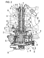
- FIG. 2 shows a sectional view of the substantial part of the variable valve drive device 200 attached to the cylinder head 104
- FIG. 3 shows an exploded perspective view of the variable valve drive device 200.
- variable valve drive device 200 rotation axes of the cam sprocket 211, exhaust cam block 220, variable camshaft 230, intake cam block 240, eccentric plate 250, and eccentric boss 260 are parallel with respect to one another.
- variable valve drive device 200 As shown in FIG. 1 to FIG. 3, the intake cam block 240 and the exhaust cam block 220 are arranged in the cylinder head 104 over the cylinder part 106 with the variable camshaft 230 inserted therein. Furthermore, the variable camshaft 230 is inserted in the cam sprocket 211, and the cam sprocket 211 and the eccentric plate 250 are arranged in the case upper part 116a.
- the eccentric boss 260 is rotatably arranged in the annular head cover 105, while the head cover 105 is fixed to the cylinder head 104. Accordingly, the variable valve drive device 200 is fixed to the cylinder head 104.
- the cam sprocket 211 is unitedly formed with the exhaust cam block 220 that has the same axile center and rotates to open and close the valve (exhaust valve, in this case) through a tubular part 224. That is, these cam sprocket 211, tubular part 224, and exhaust cam block 220 configure a cam drive section 210 that directly receives a driving force of the crankshaft 130 to rotate.
- the cam sprocket 211 is driven by the crankshaft 130 through the timing gear 134 (refer to FIG. 1) and the cam drive chain 133 (refer to FIG. 1), and rotates under a constant reduction gear ratio with respect to the number of rotations of the crankshaft 130. In this embodiment, the cam sprocket 211 rotates with half the rotational speed of the crankshaft 130.
- the axile center of the cam sprocket 211 and the exhaust cam block 220 is set to the camshaft axile center, and the camshaft axile center is arranged substantially in parallel with the crankshaft 130 (refer to FIG. 1) over the cylinder part 106.
- the cam sprocket 211 is provided with a drive pin 212 that rotates the eccentric plate 250, in such a state that drive pin 212 is so arranged as to be substantially in parallel with the rotational axis of the cam sprocket 211 and protrude toward the opposite direction with respect to the exhaust cam block220.
- the drive pin 212 is fitted with allowance in a slot 252 that is formed by cutting off part of the eccentric plate 250 from the center thereof in the radius direction.
- the axile center of the drive pin 212 is made eccentric with respect to the axile center of the cam sprocket 211.
- the drive pin 212 is made to rotate around the axile center of the cam sprocket 211 to rotate the eccentric plate 250 whose rotational axis is parallel with the drive pin 212 through the slot 252.
- the cam sprocket 211 has attached thereto a protrusion piece 114 that protrudes in the radius direction thereof.
- the protrusion piece 114 has its rotation position sensed by a sensor 114a that is attached to the cylinder head 104.
- the cam sprocket 211 Since a driving force of the crankshaft 130 is directly transmitted to the cam sprocket 211 through the cam drive chain 133 (refer to FIG. 1), the cam sprocket 211 has its rotation position determined in conjunction with the stroke of the crank. That is, the rotation position includes information of strokes of the crank (intake stroke, compression stroke, expansion stroke, and exhaust stroke, in case of the four-cycle). Accordingly, the stroke of the crank can be determined when the sensor 114a detects the position of the protrusion piece 114 attached to the cam sprocket 211.
- the same axile center of the cam sprocket 211, exhaust cam block 220, and tubular part 224, or the axile center of the cam drive section 210, is provided with an insertion opening 215 that passes through in the axis direction.
- the insertion opening 215 communicates with an opening 223 (refer to FIG. 2) that is formed on the base circle surface of the exhaust cam block 220.
- a shaft part 230a of the variable camshaft 230 is rotatably inserted in the axis direction.
- the shaft part 230a of the variable camshaft 230 protrudes from both sides of the cam drive section 210 in the axis direction, and the intake cam block 240 neighboring the exhaust cam block 220 is unitedly attached to part thereof protruding at the exhaust cam block 220 side.
- the shaft part 230a of the variable camshaft 230 is provided with a driven pin 232 at part thereof protruding at the cam sprocket 211 side of the cam drive section 210.
- variable camshaft 230 is inserted in the cam drive section 210 and is so arranged as to get across over the cylinder part 106. There are arranged a bearing 104a and a bearing 113 which rotatably support the variable camshaft 230.
- variable camshaft 230 is provided with a penetration opening 238 that passes through the inside of the shaft part 230a in the axis direction, and the penetration opening 238 works as the main path for lubricant to be supplied to the sliding parts of the members of the variable valve drive device 200.
- the penetration opening 238 is explained as a main lubricant path 238.
- the main lubricant path 238 communicates with the outer circumference surface of the shaft part 230a through branched lubricant paths 239a, 239b, 239c, and has its one end opened through an iris 235 that is arranged in the shaft part 230a at the chain line side.
- the branched lubricant paths 239a, 239b, 239c are so formed as to be perpendicular to the main lubricant path 238 at the shaft part 230a, and are opened at the outer circumference surface of the shaft part 230a, respectively.
- lubricant-pooling grooves 236, 237 are formed at the outer circumference surface of the shaft part 230a, where the branched lubricant paths 239a, 239b are opened, there are formed lubricant-pooling grooves 236, 237 in the form of recesses in the circumference direction thereof, and the branched lubricant paths 239a, 239b communicate with the lubricant-pooling grooves 236, 237.
- the lubricant-pooling grooves 236, 237 are formed at the insertion opening 215 configured by the inner surface of the tubular part 224 and exhaust cam block 220, where the outer circumference surface of the variable camshaft 230 is in contact therewith, and are filled with lubricant conducted by the branched lubricant paths 239a, 239b.
- the branched lubricant path 239c is so formed as to be perpendicular to the shaft part 230a from the main lubricant path 238, and is opened to communicate with an opening 245 of the intake cam block 240.
- lubricant conducted by the branched lubricant path 239c is supplied to the part where the shaft part 230a is in contact with the intake cam block 240, lubricating the sliding part. Furthermore, at the intake cam block 240, where the outer circumference surface of the shaft part 230a is in contact therewith, there is formed a lubricant-pooling groove 246 along the inner circumference surface of the intake cam block 240 formed at the opening thereof.
- variable camshaft 230 One end of the variable camshaft 230 is inserted into the bearing 113 attached to the cylinder head 104. Part of the variable camshaft 230 protruding from the bearing 113 is covered by an oil seal cap 115, and an oil seal part 117 prevents lubricant from leaking to the outside of the cylinder head 104.
- One end 111 of the cylinder head 104 is provided with a discharge outlet 118 of an oil pump.
- Lubricant is pressed into an oil-pooling space 119 that communicates with an opening 230c formed at one end of the shaft part 230a through the discharge outlet 118, and lubricant is conducted to the main lubricant path 238 through the oil-pooling space 119.
- the intake cam block 240 is fitted to the outside of one end of the shaft part 230a, and a pin 241 is fitted into a cutout 243 (refer to FIG. 3) formed on the inner circumference surface of the intake cam block 240, fixing the intake cam block 240.
- the intake cam block 240 is arranged over the cylinder part 106 together with the exhaust cam block 220.
- the intake cam block 240 When the variable camshaft 230 rotates with its axile center being the rotation center, the intake cam block 240 is made to rotate with the same axile center being the rotation center. Furthermore, as shown in FIG. 2, the intake cam block 240 has formed thereon the opening 245 penetrating from the base circle surface thereof to the opening inner surface thereof formed at one end of the outer circumference surface of the shaft part 230a. The opening 245 communicates with the main lubricant path 238 inside the shaft part 230a.
- the main lubricant path 238 is formed in the shaft part 230a of the variable camshaft 230, penetrating therethrough in the axis direction, and the variable camshaft 230 has its another end made to neighbor the eccentric plate 250 and has its one end provided with the intake cam block 240. Accordingly, the main lubricant path 238 penetrates the intake cam block 240, exhaust cam block 220, and further penetrates the cam sprocket 211 neighboring the exhaust cam block 220, getting to the eccentric plate 250.
- the main lubricant path 238 penetrates the cam sprocket 211 from one end thereof and has its another end opened through the iris 235.
- the iris 235 optimally distributes lubricant to be supplied to the valve drive part (exhaust cam block 220, intake cam block 240) side and to the variable mechanism part (eccentric plate 250, drive pin 212, driven pin 232, slots 252, 254, etc.) side.
- the main lubricant path 238 gets across in the cylinder head 104 over the cylinder part 106.
- lubricant supplied from one end of the shaft part 230a passes over the cam sprocket 211 that is directly driven by the crankshaft 130, and flows to the eccentric plate 250 located at the other end of the shaft part 230a through the iris 235.
- the shaft part 230a has its another end provided with a plate 234, which extends in a direction substantially perpendicular to the axile center of the shaft part 230a.
- the plate 234 is made to rotate at a position neighboring the cam sprocket 211 when the shaft part 230a rotates.
- the plate 234 is provided with the driven pin 232 (refer to FIG. 1 to FIG. 3), which protrudes in a direction opposite to the direction along which the shaft part 230a extends.
- the driven pin 232 is arranged in parallel with the axile center of the shaft part 230a, and is located at a position eccentric with respect to the axile center of the shaft part 230a on the opposite side of the drive pin 212 when viewed from the shaft part 230a.
- the driven pin 232 is fitted with allowance in a slot 254 that is formed by cutting off part of the eccentric plate 250 from the center thereof in the radius direction, and is made to rotate around the axile center of the shaft part 230a when the eccentric plate 250 rotates. That is, when the drive pin 212, which is made to rotate when the cam sprocket 211 rotates, rotates the eccentric plate 250, the intake cam block 240 is made to rotate when the variable camshaft 230, which is driven by the eccentric plate 250 through the driven pin 232, rotates.
- the eccentric plate 250 includes a plate main body 256 in the form of a plate that is so arranged as to neighbor the plate 234 of the variable camshaft 230, and a plate shaft part 258 arranged at the center of the plate main body 256.
- the plate main body 256 has formed thereon the slot 252 and the slot 254 in alignment, sandwiching the plate shaft part 258, in which the drive pin 212 and the driven pin 232 are fitted with allowance respectively.
- the plate shaft part 258 is so formed as to be perpendicular to the plate main body 256 and protrude to the side opposite to the plate 234, and is rotatably inserted in an eccentric opening 262 formed through the eccentric boss 260.
- the eccentric opening 262 is formed through an eccentric boss main body 264 that is rotatably arranged in the inside of the head cover 105 attached to the cylinder head 104, and is located at a position eccentric with respect to the rotation center R (refer to FIG. 3).
- the eccentric boss main body 264 has a rack 266 formed on part of the outer circumference thereof, which is engaged with a worm gear 272 of the eccentricity-causing motor 270 attached to the head cover 105. Accordingly, when the eccentricity-causing motor 270 is driven, the eccentric opening 262 can shift, keeping its position eccentric with respect to the rotation center R of the eccentric boss main body 264.
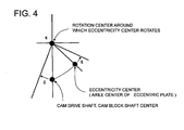
- FIG. 4 shows a view indicative of the positional relationship among the rotation center R of the eccentric boss 260, the axile center C of the variable camshaft 230, and the axile center E of the eccentric plate 250.
- the eccentric boss 260 is rotatably fitted into the head cover 105, and is made to rotate by the eccentricity-causing motor 270 (refer to FIG. 1 to FIG. 3) with the rotation center (boss center) R being the center.
- the rotation center R is fixed to the engine side, and is the rotation center of the axile center (eccentricity center) E with respect to the axile center C of the variable camshaft 230, exhaust cam block 220, and intake cam block 240.
- the axile center E of the plate shaft part 258 or the eccentric plate 250 is rotatably inserted to the eccentric opening 262 of the eccentric boss 260, when the eccentric boss 260 rotates, the axile center (eccentricity center) E of the eccentric plate 250 is made to shift with the rotation center (boss center) R being the center, depicting a circular arc. Furthermore, on a line along which the axile center (eccentricity center) E shifts, the axile center C of the variable camshaft 230 or the axile center C of the exhaust cam block 220 and intake cam block 240 is located.
- the axile center E of the eccentric plate 250 is made eccentric with respect to the axile center C of the variable camshaft 230, which can bring about a phase difference in the rotation of the intake cam block 240 united with the variable camshaft 230 with respect to the rotation of the exhaust cam block 220 united with the cam sprocket 211.
- the rotation of the eccentric boss 260 can make the axile center E accord with the axile center C.
- the eccentric boss 260 can be fixed. Accordingly, the eccentric plate 250 and the variable camshaft 230 can be made to rotate with the same axile center being the rotation center.
- the rotation angle of the eccentric boss 260 in the head cover 105 is detected by angle sensors 26, 27 which are attached to the eccentric boss 260, as shown in FIG. 2. Using thus detected information, information obtained from the engine side such as the engine rotation and engine load, and information input by the user through an operation unit, not shown, the eccentric position of the eccentric opening 262 is controlled to be set to a predetermined position by a control unit, not shown.
- FIG. 5 shows an exploded perspective view of the eccentric boss 260.
- the eccentric boss main body 264 of the eccentric boss 260 is in the form of a cylinder having the bottom, and is formed by attaching a lid 264b to a main case 264a having formed therethrough the eccentric opening 262.
- the main case 264a has formed therein separated spaces 267a, 267b, 267c around the eccentric opening 262, the spaces being partitioned by partition walls 265a, 265b, 265c.
- Each of the partition walls 265a, 265b is provided with a cutout 269 that makes the separated space 267a communicate with the separated space 267b, and makes the separated space 267b communicate with the separated space 267c.
- the lid 264b covers the separated spaces 267a, 267b, 267c.
- the lid 264b has formed therethrough an opening 264c at a position corresponding to the ceiling of the separated space 267c.
- the eccentric boss 260 is of communicating configuration in the axis direction or from the front side to the rear side through the air holes 268, separated spaces 267a, 267b, 267c, cutouts 269, and opening 264c. That is, even if the eccentric boss 260 is attached to the cylinder head 104 through the head cover 105, the eccentric boss 260 can make the front side thereof communicate with the rear side thereof in the cylinder head 104.
- the head cover 105 has formed therethrough oil return holes 105a substantially in parallel with the rotation axile center of the eccentric boss 260.
- the lubricant is made to return to flow into the engine 100 through the oil return holes 105a together with the oil return hole 268a making the separated space 267a communicate with the outside thereof. That is, the separated spaces 267a, 267b, 267c work as breather spaces which prevent discharging lubricant in blow-by gas raised in the engine 100 to the outside of the engine 100.
- variable valve drive device 200 in this embodiment will be explained.
- variable valve drive device 200 shown in FIG. 1 to FIG. 3, when the crankshaft 130 rotates, the cam sprocket 211 is made to rotate through the cam drive chain 133 with half the rotational speed of the crankshaft 130. At this time, the exhaust cam block 220 that is unitedly attached to the cam sprocket 211 through the tubular part 224 is made to rotate. That is, the exhaust cam block 220 rotates in synchronization with the rotation of the crankshaft 130.
- the drive pin 212 that is fitted with allowance in the slot 252 of the eccentric plate 250 presses the eccentric plate 250 through the slot 252 with the plate shaft part 258 being the supporting point so as to rotate the eccentric plate 250. Since the rotation center of the eccentric plate 250, that is, the position of the plate shaft part 258 is made eccentric due to the drive of the eccentricity-causing motor 270, even if the cam sprocket 211 rotates with a constant rotational speed, the eccentric plate 250 is made to rotate with a non-constant rotational speed.
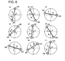
- FIG. 6 shows a view indicative of an example of the positional relationship between the drive pin 212 and the driven pin 232 in the present variable valve drive device 200 when the center of the eccentric plate 250 is made eccentric with respect to the variable camshaft 230.
- FIG. 6 (a) to FIG. 6 (i) show the relative positional relationship between the drive pin 212 and the driven pin 232 in stages when the crankshaft 130 is made to rotate with a predetermined rotational speed. Since the slots 252 and 254 (refer to FIG. 1 to FIG. 3) in which the drive pin 212 and driven pin 232 are fitted with allowance are formed in alignment, thus formed line is simply represented by a straight line SL.
- the distance between the center of the eccentric plate 250 and the center of the drive pin 212 becomes shorter than the distance between the center of the cam sprocket 211 and the center of the drive pin 212. Accordingly, the rotation angle of the eccentric plate 250 becomes larger than the rotation angle of the cam sprocket 211.
- the slot 254 formed on the plate main body 256 of the eccentric plate 250 is made to rotate with a non-constant rotational speed similar to the eccentric plate 250. Since the driven pin 232 that is fitted with allowance in the slot 254 is concentric with the cam sprocket 211 and the intake cam block 240, the rotation with a non-constant rotational speed is transmitted to the driven pin 232 through the slot 254. Then, the shaft part 230a is made to rotate with a non-constant rotational speed through the driven pin 232 to which the rotation with a non-constant rotational speed is transmitted, which makes the intake cam block 240 rotate with a non-constant rotational speed.
- the intake cam block 240 rotates with an angular speed that is faster than half the rotational speed of the crankshaft 130 around the crank angle at which the intake cam block 240 is opened.
- the crank rotates by the duration (for example, 268 degrees)
- the intake cam is made to rotate more than the duration
- the intake valve is opened and closed in a shorter time period. That is, the duration is made narrow.
- the duration is made broad.
- the rotational phase difference of the intake cam block 240 that is made to rotate by the variable camshaft 230 driven through the eccentric plate 250 periodically fluctuates with respect to the exhaust cam block 220 that is unitedly attached to the cam sprocket 211. That is, the duration of the intake cam block 240 periodically varies, that is, the intake cam block 240 rotates with a non-constant rotational speed, which varies the duration as well as opening and closing timing of the intake valve (variable valve) to be opened and closed by the rotation.
- At which timing the intake cam block 240 should be made to rotate with a higher speed and should be made to rotate with a lower speed with respect to the exhaust cam block 220 is determined by the positional relationship among the center of the eccentric plate 250 and the cam nose as well as the respective slots 252, 254 with respect to the center of the cam sprocket 211.
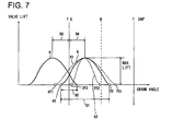
- FIG. 7 shows a view indicative of an example of the valve lift by the variable valve drive device 200 according to an embodiment of the present invention.
- a lift curve K indicates the lift amount by the intake valve
- a lift curve H indicates the lift amount by the exhaust valve.
- OT, OT1, OT2 indicate the opening timing of the variable valve (intake valve, in this case), while TT, TT1, TT2 indicate the closing timing thereof.
- the duration (also referred to as working angle) D1 of the intake cam block 240, valve overlap D2, maximum lift angles D3, D4 are shown.
- the lift curve K is varied as shown by lift curves K1, K2.
- the rotational speed of the cam is made low during a period when the valve is opened, while the rotational speed of the cam is made high when the valve is closed.
- the rotational speed of the cam is made high during a period when the valve is opened, while the rotational speed of the cam is made low when the valve is closed.
- the intake cam block 240 can be made to rotate with a periodical rotational phase difference set up with respect to the exhaust cam block 220, and the rotational phase difference can be arbitrarily varied, the length of the valve overlap D2 can be varied depending on the engine stroke.
- the interfusion of residual gas can be prevented, making it possible to combust gas with stability.
- the scavenging for the residual gas due to the effect of the exhaust-pulse and reduction of blowing back can be realized.
- the intake effect for air fuel mixture is improved, which enables taking in sufficient air fuel mixture, making it possible to stabilize the idling as well as improve the starting capability.
- blow-bye can be prevented, and hydrocarbon contained in exhaust gas can be reduced, and the engine power at a low rotational speed can be enhanced, enabling the improvement of the fuel consumption.
- the intake cam block 240 is made to rotate such that the intake valve is fully closed when the piston 102 gets to the bottom dead point.
- the pumping loss can be reduced by largely opening the intake valve earlier to largely gain the overlap, which can improve the combustion efficiency, enabling the improvement of the fuel consumption.
- variable valve drive device 200 lubricant is effectively supplied to the sliding parts of the members.
- FIG. 8 shows a view indicative of the flow of lubricant in the variable valve drive device 200 according to an embodiment of the present invention.
- lubricant that is pumped up from an oil pan 620 (refer to FIG. 9) by a pump, not shown, is discharged from the discharge outlet 118.
- Lubricant coming from the discharge outlet 118 flows (in a direction of an arrow S1 shown in FIG. 8) into the oil-pooling space 119 in the oil seal cap 115 that is arranged at the one end 111 (end of the cylinder part 106) side of the sealed cylinder head 104.
- the flowing lubricant is made to flow (in a direction of an arrow S2 shown in FIG. 8) into the main lubricant path 238 in the shaft part 230a from the opening 230c formed at one end of the rotating shaft part 230a.
- Lubricant flowing into the main lubricant path 238 flows to the chain line side of the shaft part 230a.
- the lubricant passes through the branched lubricant path 239c, and flows (in a direction of an arrow S3 shown in FIG. 8) to the outside of the intake cam block 240 from the opening 245, reducing the friction raised in the sliding part of the intake cam block 240.
- lubricant in the main lubricant path 238 flows (in a direction of an arrow S4 shown in FIG. 8) into the lubricant-pooling groove 237 from the branched lubricant path 239b to lubricate the sliding part raised with the exhaust cam block 220. Furthermore, lubricant coming from (in a direction of the arrow S4 shown in FIG. 8) the branched lubricant path 239c lubricate the base circle surface of the exhaust cam block 220 from the opening 223.
- lubricant in the main lubricant path 238 flows (in a direction of an arrow S5 shown in FIG. 8) into the lubricant-pooling groove 236 from the branched lubricant path 239a to lubricate the sliding part between the tubular part 224 and the bearing 104a arranged in the cylinder head 104.
- lubricant in the main lubricant path 238 flows (in a direction of an arrow S6 shown in FIG. 8) to the chain line side of the shaft part 230a, and flows to the outside from one end of the shaft part 230a, specifically, from the axile center thereof located at the surface of the plate 234 through the iris 235.
- lubricant coming from the main lubricant path 238 lubricates the sliding part raised with other members of the eccentric plate 250.
- lubricant discharged from (in directions of arrows S7, S8 shown in FIG. 8) the variable camshaft 230 lubricates the sliding parts between the plate main body 256 (slots 252, 254) and the drive pin 212 as well as the driven pin 232.
- the drive pin 212 is made of material that is obtained by treating steel product of high hardness with heat
- the eccentric plate 250 is made of high alloy steel, cast iron, or sintered alloy of iron which are excellent in abrasion resistance, and the slots 252, 254 have their surface treated so as to improve the hardness.
- the sliding part between the cam sprocket 211 and the cam drive chain 133 (refer to FIG. 1) is lubricated (in directions of arrows S9, S10 shown in FIG. 8) by lubricant.
- variable valve drive device 200 as compared with a camshaft that is not provided with the variable valve drive mechanism, or the variable valve timing mechanism, the positional relationship among the exhaust cam block 220, intake cam block 240, and cam sprocket 211 is not varied on the cam axis line.
- variable valve drive device 200 can be mounted by replacing the camshaft with the variable valve drive device 200.
- variable valve drive device 200 in mounting the variable valve drive device 200, the dimension, arrangement position, etc. of the respective members to drive the camshaft such as the crankshaft, and the cylinder part, cylinder head, timing gear, etc. of the engine main body do not have to be changed.
- the variable valve drive device 200 and the head cover 105 are dismounted from the engine main body 110. Then, a crankshaft which is not provided with the variable mechanism such as the eccentric plate 250, and includes a cam sprocket, an exhaust cam block, an intake cam block, etc. is inserted into the cylinder head, and a head cover that is formed to correspond to the crankshaft is fixed to the cylinder head. In this way, it becomes possible to easily change the motorcycle 500 provided with the variable valve drive device 200 to a motorcycle that is not provided with the variable valve drive device 200.
- a vehicle to which the engine 100 is mounted is a scooter-type motorcycle.
- a vehicle to which the engine 100 is mounted is not restricted to this, and any vehicle may be employed so long as the vehicle has mounted thereto the engine 100.
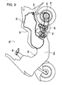
- FIG. 9 shows a schematic side view indicative of the substantial configuration of a motorcycle provided with the variable valve drive device for an engine according to an embodiment of the present invention.
- the front, rear, left, right mean the front, rear, left, right which are seen at the time of sitting on the seat of the motorcycle.
- the motorcycle in this embodiment is of the scooter-type.
- any vehicle may be employed so long as the vehicle is provided with the valve drive device.
- the motorcycle 500 shown in FIG. 9 is of the tandem-scooter-type, and includes a vehicle main body 503 that pivotably supports a handle 502 at the front side thereof, and a tandem seat 504 that is arranged at the rear side of the vehicle main body 503.
- the tandem seat 504 is openably attached to a trunk space 505 arranged on the lower side. Under the trunk space 505, there is arranged a drive unit 600.
- the front end of the drive unit 600 is swingablly attached to the rear side of a front side main body 503a that extends backward from the lower side of the handle 502 to the lower side of the tandem seat 504 in the upward and downward direction through a pivot shaft, not shown, which is arranged on the level in a direction of the vehicle width.
- rear wheels 508 are attached through an axile 510, and there are suspended rear suspensions 512 between the rear ends of the axile 510 and frame pivots which support the rear end of the trunk space 505.
- the front end of the trunk space 505 is located at the upper front side of the front end of the drive unit 600.
- FIG. 10 shows a schematic plan view indicative of the substantial part of the drive unit 600 shown in FIG. 9.
- the engine 100 is mounted at the front side of the vehicle, and a driving force generated from the engine 100 is transmitted to the axile 510 that is attached to the rear end of the drive unit 600 through a CTV mechanism 610 to rotate the rear wheels 508.
- the engine 100 has the axis line of the cylinder part 106 made substantially horizontal, and has the crankshaft 130 made substantially parallel with a direction of the vehicle width, and is arranged at substantially the central part in the forward and backward direction of the vehicle under the trunk space 505.
- the CTV mechanism 610 At the other end side of the crankshaft 130, or at the left side end of the vehicle in this case, there is arranged the CTV mechanism 610 that extends backward in the vehicle.
- the CTV mechanism 610 is arranged substantially in parallel with the cylinder axis, and includes a pulley 611 attached to the crankshaft 130, a pulley 612 attached to the axile 510, a belt 613 that is wound around the pulleys 611, 612, and a centrifugal clutch 614.
- the centrifugal clutch 614 is attached to the axile 510. Furthermore, the axile 510 has attached thereto a reduction gear 615 that reduces the speed brought about by a driving force of the crankshaft 130 which is transmitted through the pulley 611 and belt 613.
- variable valve timing mechanism is mounted to motorcycles, and especially, in case of applying the variable valve timing mechanism to a scooter-type vehicle (referred to as scooter, hereinafter), so as to restrict the vehicle dimension, it is desirable that the engine configuration is simplified.
- scooter scooter-type vehicle
- the eccentric plate 250 that corresponds to the eccentric member is not arranged between the cam drive section 210 that corresponds to the cam drive shaft and the exhaust and intake cam blocks 220, 240 which are arranged over the cylinder part 106 in the conventional engine configuration.
- the exhaust and intake cam blocks 220, 240 are arranged along a cylinder axis line CL over the cylinder part 106, being different from the conventional configuration, the cylinder axis line and the cam chain line are arranged at positions neighboring one another.
- a chain line L of the engine 100 is located at a position in close proximity to the cylinder axis line CL.
- the belt 613 line of the CTV mechanism 610 which is arranged substantially in parallel with the chain line L at the outside of the chain line L comes close to the cylinder axis line CL as compared with the conventional configuration.
- the scooter-type motorcycle 500 is provided with parts arranged at the outside of the cam drive chain 133 on the crankshaft 130 such as a sheave for the CVT (Continuously Variable Transmission).
- CVT Continuous Variable Transmission
- members for the variable valve drive are not arranged between the chain line L of the cam drive chain 133 and the cylinder axis line CL on the camshaft line. Accordingly, on the crankshaft 130, it is not necessary to provide a space corresponding to the members, and the cam sprocket 211 and the exhaust and intake cam blocks 220, 240 are not separately arranged as compared with an engine provided with the conventional variable valve timing mechanism.
- the chain line L of the cam drive chain 133 that is arranged in a direction substantially perpendicular to the crankshaft 130 is not separated from the cylinder axis line CL.
- the width of the crank case 112 comes to be equal to that in the configuration in which the variable valve timing mechanism is not mounted.
- a sufficient banking angle can be prepared in the motorcycle 500, making it possible to secure the motional characteristics.
- the eccentric mechanism such as the eccentric plate 250 is not arranged between the exhaust and intake cam blocks 220, 240 and the cam sprocket 211.
- substantially similar corresponding components of an engine that is not provided with the variable valve drive device 200 can be used. That is, only by dismounting the variable valve drive device 200 from the cylinder head 104 of the engine main body 110, and changing the eccentric plate 250, variable camshaft 230, eccentric boss 260, and head cover 105, an engine that is not provided with the variable valve drive device 200 can be formed.
- main engine components such as the cylinder head can be used in common with the conventional engine of the invariable specification.
- the overlap can be made variable with simplified configuration.
- the duration of cams can be made variable with simplified configuration without widely changing the engine configuration, making it possible to realize high response and high mileage in the engine.
- the single cylinder SOHC (Single Over Head Camshaft) type is employed, to which the present invention is not restricted, and the multi-cylinder SOHC type, DOHC (Double Over Head Camshaft) may be employed.
- SOHC Single Over Head Camshaft
- DOHC Double Over Head Camshaft
- the rotational phase difference of the intake cam block 240 is made to periodically fluctuate with respect to the exhaust cam block 220, to which the present invention is not restricted. That is, the rotational phase difference of the exhaust cam block 220 may be made to periodically fluctuate with respect to the intake cam block 240.
- an intake cam block that rotates unitedly with the cam sprocket 211 and drives the intake valve is arranged, and the variable camshaft 230 is provided with an exhaust cam block that drives the exhaust valve.
- a variable valve drive device which includes a cam drive member that is made to rotate by a driving force transmitted from a crankshaft, an eccentric member that is made to rotate with an axis of the same direction as the rotation axis of the cam drive member being the rotation center when the cam drive member is driven, and has the axis shiftably arranged from the axile center of the rotation axis to an eccentric position, a camshaft that is arranged on the same axis as the rotation axis, and is made to rotate by the eccentric member with the rotation axis being the rotation center, and the rotational phase difference thereof with respect to the cam drive member periodically fluctuates when the eccentric member is made to rotate at the eccentric position, and a cam block that is made to rotate by the camshaft with the same rotational phase as that of the camshaft so as to drive an exhaust valve or an intake valve, wherein the eccentric member is arranged at one end of the cam drive member in the rotation axis direction thereof, and the cam block is
- the camshaft is made to rotate with its rotational phase difference with respect to the cam drive member periodically fluctuating.
- the cam block that is made to rotate with the same rotational phase as that of the camshaft has its rotational phase difference with respect to the cam drive member made to periodically fluctuate. That is, the duration of the cam block becomes variable, which makes the duration of the exhaust valve or intake valve to be driven by the cam block variable. Since the duration of the exhaust valve or intake valve is made variable, the valve overlap becomes variable.
- the overlap when employed in an engine of the same cylinder capacity, the overlap can be made short at the time of low-speed rotation (including idling) of the engine, while the overlap can be made short at the time of high-speed rotation.
- the valve when the engine is in the low rotational speed state including the idling, the valve is opened or closed earlier so as to reduce or remove the overlap, which can prevent the interfusion of residual gas (combustion gas), making it possible to combust gas with stability.
- the scavenging for the residual gas due to the effect of the exhaust-pulse and reduction of blowing back can be realized. Moreover, it becomes possible to stabilize the idling as well as improve the starting capability. Furthermore, blow-bye can be prevented, and hydrocarbon contained in exhaust gas can be reduced, and the engine power at a low rotational speed can be enhanced, enabling the improvement of the fuel consumption.
- variable valve drive device when the engine is in the medium rotational speed state, the pumping loss can be reduced by largely gaining the overlap, which can improve the combustion efficiency. In this way, employing the variable valve drive device according to the present invention, the engine capability can be improved without changing the cylinder capacity.
- the eccentric member is not arranged between the cam drive member and the cam block, and the positional relationship between the exhaust valve or intake valve and the cam drive member is similar to that of the conventional engine.
- the present variable valve drive device can be mounted to a conventional engine without widely changing the engine configuration. That is, main engine components can be used in common in an engine that is provided with the variable valve mechanism and in an engine that is not provided with the variable valve mechanism. Accordingly, in case of mounting the present variable valve drive device to an engine, which is mounted to a motorcycle and is not provided with the variable valve mechanism, it is not necessary to change other engine components such as the cylinder, crankshaft, etc., which can widely reduce the cost.
- the transmission means does not protrude to the outside, which does not enlarge the width of the engine itself, preventing the reduction of the banking angle as well as the lowering of the travel capability of the vehicle.
- variable valve drive device further includes a member-shifting part that shifts the axis of the eccentric member from the axis position to an eccentric position with respect to the rotation axis of the cam drive member.
- the duration of the exhaust valve or intake valve can be made variable.
- variable valve drive device further includes another cam block that is made to rotate by the cam drive member with the same rotational phase as that of the cam drive member, and is arranged at a position neighboring the cam block.
- variable valve drive device can be easily mounted to the SOHC type engine in which the intake valve and exhaust valve are arranged on the same camshaft, which can improve the degree of freedom in employing the variable valve drive device.
- the cam block rotates to drive an intake valve, while another cam block rotates to drive an exhaust valve.
- the duration of the intake valve can be made variable with respect to the duration of the exhaust valve.
- the overlap can be largely gained by elongating the opened period of the intake valve, which can secure the engine capability at the time of high-speed rotation without laying down the output capability at the time of low-speed rotation.
- the cam block rotates to drive an exhaust valve, while another cam block rotates to drive an intake valve.
- the duration of the exhaust valve can be made variable with respect to the duration of the intake valve.
- the opened period of the exhaust valve can be made variable without changing the opened period of the intake valve, which can secure the engine capability at the time of high-speed rotation without laying down the idle stability.
- a variable valve drive device which includes a cam drive member that is made to rotate by a driving force transmitted from a crankshaft, an eccentric member that is arranged at one end of the cam drive member in the rotation axis direction thereof, and is made to rotate with an axis of the same direction as the rotation axis of the cam drive member being the rotation center when the cam drive member is driven, and has the axis shiftably arranged from the axile center of the rotation axis to an eccentric position, a camshaft that is arranged on the same axis as the rotation axis, and is made to rotate by the eccentric member with the rotation axis being the rotation center, and the rotational phase difference thereof with respect to the cam drive member periodically fluctuates when the eccentric member is made to rotate at the eccentric position, a first valve-driving cam block that is arranged at the other end of the cam drive member in the rotation axis direction thereof, and is made to rotate with the same rotational phase as that of the camshaft
- variable valve drive device since other members are not arranged between the two valve-driving cam blocks, the variable valve drive device can be compactly configured.
- an engine which includes a variable valve drive device including a cam drive member that is made to rotate by a driving force transmitted from a crankshaft, an eccentric member that is made to rotate with an axis of the same direction as the rotation axis of the cam drive member being the rotation center when the cam drive member is driven, and has the axis shiftably arranged from the axile center of the rotation axis to an eccentric position, a camshaft that is arranged on the same axis as the rotation axis, and is made to rotate by the eccentric member with the rotation axis being the rotation center, and the rotational phase difference thereof with respect to the cam drive member periodically fluctuates when the eccentric member is made to rotate at the eccentric position, and a cam block that is made to rotate by the camshaft with the same rotational phase as that of the camshaft so as to drive an exhaust valve or an intake valve, wherein the eccentric member is arranged at one end of the cam drive member in the rotation axis direction thereof, the cam block
- the eccentric member for improving the engine capability is not arranged between the cam drive member and the cam block, and the positional relationship between the exhaust valve or intake valve and the cam drive member is similar to that of the conventional engine, in which the cylinder capacity is not changed. Accordingly, the variable valve drive device can be mounted without widely changing the conventional engine configuration. That is, main engine components can be used in common in an engine that is provided with the variable valve mechanism and in an engine that is not provided with the variable valve mechanism. Accordingly, in case of mounting the variable valve drive device to an engine, which is mounted to a motorcycle and is not provided with the variable valve mechanism, for assembling, it is not necessary to change other engine components such as the cylinder, crankshaft, etc., which can widely reduce the cost in assembling.
- the width of the crankshaft does not become large accordingly.
- the driving force transmission line from the crankshaft to the cam drive member is separated from the cylinder axis line on which the cam block is arranged.
- the transmission means does not protrude to the outside, which does not enlarge the width of the engine itself, preventing the reduction of the banking angle as well as the lowering of the travel capability of the vehicle.
- an engine which includes a variable valve drive device including a cam drive member that is made to rotate by a driving force transmitted from a crankshaft, an eccentric member that is arranged at one end of the cam drive member in the rotation axis direction thereof, and is made to rotate with an axis of the same direction as the rotation axis of the cam drive member being the rotation center when the cam drive member is driven, and has the axis shiftably arranged from the axile center of the rotation axis to an eccentric position, a camshaft that is arranged on the same axis as the rotation axis, and is made to rotate by the eccentric member with the rotation axis being the rotation center, and the rotational phase difference thereof with respect to the cam drive member periodically fluctuates when the eccentric member is made to rotate at the eccentric position, a first valve-driving cam block that is arranged at the other end of the cam drive member in the rotation axis direction thereof, and is made to rotate with the same rotational phase as that of the
- the engine can be compactly configured.
- the engine is of the single cylinder type.
- the valve when employing the single cylinder type, due to the simply configured variable valve drive device, the valve can be opened and closed corresponding to the engine at the time of low-speed rotation and high-speed rotation.
- a motorcycle that has mounted thereto the engine such that the crankshaft is arranged in a direction of the vehicle width.
- the width of the crankshaft does not become large accordingly.
- the driving force transmission line from the crankshaft to the cam drive member is separated from the cylinder axis line on which the cam block is arranged.
- the transmission means does not protrude to the outside, which does not enlarge the width of the engine itself, preventing the reduction of the banking angle as well as the lowering of the vehicle travel capability.
- the duration of cams can be made variable with a simplified configuration without considerably changing the configuration of an engine.
Landscapes
- Engineering & Computer Science (AREA)
- Mechanical Engineering (AREA)
- General Engineering & Computer Science (AREA)
- Valve Device For Special Equipments (AREA)
- Valve-Gear Or Valve Arrangements (AREA)
Abstract
In a variable valve drive device, a cam sprocket 211 is made to rotate by a driving force transmitted from a crankshaft 130. An eccentric plate 250 is arranged at one end side of the cam sprocket 211 in the rotation axis direction thereof, and is made to rotate around an axis in the same direction as the rotation axis of the cam sprocket 211. The axis of the eccentric plate 250 is shiftable from the axile center of the rotation axis to an eccentric position. A variable camshaft 230 is made to rotate around its rotation axis by the eccentric plate 250, and when the eccentric plate 250 rotates the variable camshaft 230 at the eccentric position, the rotational phase difference thereof with respect to the cam sprocket 211 periodically fluctuates. An intake cam block 240 is arranged at the other end side of the cam sprocket 211 in the rotation axis direction thereof, and is made to rotate by the variable camshaft 230 with the same phase as that of the variable camshaft 230 to drive an intake valve.
Description
- The present invention relates to a variable valve drive device that is arranged in an engine, an engine, and a motorcycle.
- Conventionally, in the four-cycle engine, by changing the valve overlap or a period during which the intake valve and the exhaust valve are opened concurrently at the time of the high-speed rotation and the low-medium-speed rotation respectively, high output and low mileage of engine as well as reduction of exhaust gas are realized.
- As a mechanism to change the valve overlap depending on the rotation of an engine, there is known the variable valve timing mechanism that changes the opening and closing timing of the valves according to the number of revolutions of an engine.
- As a general variable valve timing mechanism, for example, there is known one mechanism in which, at the sprocket part for driving cams which rotates in conjunction with the rotation of the crank, a rotational phase difference is set up between the cam drive shaft part rotating in conjunction with the rotation of the crankshaft and a part that drives the camshaft part to which cams are unitedly fixed.
- Being a mechanism in which the valve timing is varied without changing the duration (also referred to as working angle) of cams, the variable valve timing mechanism of this type can be realized by only changing a part of the cam sprocket part rotating in conjunction with the rotation of the crankshaft without largely changing the valve drive mechanism in the conventional engine. However, under this configuration, since the duration of cams cannot be changed, in case of using cams of a large duration so as to obtain a high output, the flow velocity of air fuel mixture flowing into the cylinder is reduced at the time of the low-medium-speed rotation. Accordingly, air fuel mixture becomes hard to vaporize completely in the cylinder, raising a problem that a high output cannot be realized.
- As a technology to make the duration of cams variable, there is suggested one that makes the reduction ratio of the cam angle with respect to the crank angle periodically fluctuate by arranging a coupling (eccentric member) that brings about the angular velocity fluctuation between the cam drive shaft part and the camshaft part, and controls the fluctuation. For example, in
Patent Document 1, the cam drive shaft that is driven by the rotation of the crank is made to pass through cams and an eccentric plate (eccentric member) in the form of a circular disc, and a pin arranged on the cam drive shaft is fitted with allowance in a groove extending in the radius direction at the eccentric plate. Then, when the cam drive shaft rotates, the eccentric plate is made to rotate eccentrically with respect to the cam drive shaft through the pin and groove to drive the cams. As a technology having a fundamental configuration similar to that of thePatent Document 1, there is known Patent Document 2. - Furthermore, in
Patent Document 3, an eccentric plate is arranged between a sprocket that rotates when a driving force is transmitted from the crankshaft through a gear train and the camshaft that is unitedly fixed to cams, and a motive energy is transmitted to the camshaft from the sprocket through the eccentric plate. - These variable valve timing mechanisms are mainly applied to a multi-cylinder engine of an automobile. In a multi-cylinder engine, since the periodical velocity fluctuation of cams in respective cylinders are required to be staggered by setting different phases, each cylinder has an eccentric plate.
- Furthermore, as another configuration of the variable valve timing mechanism, there is known
Patent Document 4. ThisPatent Document 4 discloses a technology in which the cam drive shaft itself, which drives the camshaft that is unitedly fixed to cams, is made eccentric with respect to the camshaft by an eccentric mechanism. - Patent Document 1: Jpn. Pat. Appln. Publication No.
47-020654 - Patent Document 2: Jpn. Pat. Appln. Laid-Open Publication No.
5-118208 - Patent Document 3: Jpn. Pat. Appln. Laid-Open Publication No.
3-43611 - Patent Document 4: Jpn. Pat. Appln. Publication No.
61-56408 - In recent years, due to the problem of the exhaust gas regulation etc., mounting the variable valve timing mechanism to motorcycles are being considered. When applying the variable valve timing mechanism to a motorcycle, especially to a scooter-type vehicle (referred to as scooter, hereinafter), depending on the restriction of the vehicle dimension, it is desired that the engine configuration is simplified.
- However, according to the technologies disclosed in
Patent Document 1 toPatent Document 3, the coupling (for example, an eccentric plate) as a variable mechanism that changes the duration of cams is arranged between the drive part (cam sprocket) that rotates together with the cam drive shaft under the same rotation and the camshaft. Accordingly, in case of mounting the variable valve timing mechanism to a motorcycle, it is necessary to considerably change the configuration of the conventional engine of conventional invariable specification in which a cam drive member is arranged at a position in close proximity to the cylinder axis. That is, in case of changing an engine of conventional invariable specification into an engine of variable specification, there is brought about the necessity of changing main engine components such as the cylinder head, a component that transmits a driving force from the crankshaft to the cam drive shaft. Accordingly, there is raised a problem that main components of an engine of invariable specification cannot be used in an engine of invariable specification. - In case of realizing the variable valve timing mechanism by employing the technology disclosed in
Patent Document 4, it is possible to use main components in common to a certain extent. However, according to the technology disclosed inPatent Document 4, since the cam drive shaft itself is made to shift, along with the configuration of shifting the cam drive shaft, the configuration of driving cams and the configuration of making the valve timing variable become necessarily complicated. - Furthermore, since an engine of a motorcycle has arranged therein an eccentric mechanism such as an eccentric plate between the cam sprocket and the camshaft, the cam sprocket comes to be separated from the cylinder axis, which lowers the flexural strength of the crank. There is raised a problem that it is difficult to mount the variable valve timing mechanism with the lowering of the flexural strength being prevented.
- Furthermore, as compared with a conventional engine, since the cam sprocket and the cylinder axis are separately arranged, the chain line of the cam drive chain which is so arranged as to be substantially perpendicular to the crankshaft is separated from a line on which a cylinder and cams are arranged. Accordingly, an engine itself becomes large by a distance between the arrangement line for the cylinder as well as cams and the chain line. As a result, when an engine is employed in a motorcycle, in case the variable valve timing mechanism is mounted to the engine, the chain line protrudes to the outside of the engine as compared with the conventional engine, raising a problem that the engine itself is enlarged.
- Especially, in a scooter, structurally, a sheave for the CVT (Continuously Variable Transmission) is arranged, on the crankshaft, at the outside of the cam drive chain away from the vehicle center. Accordingly, in case of mounting the conventional variable valve timing mechanism to a scooter, wide components such as a sheave are arranged, on the crankshaft, at the outside of rotating parts (crank pulley, timing gear, etc.) around which the cam drive chain is wound with respect to the cylinder position. Accordingly, an engine itself wholly protrudes toward a direction of the crankshaft as compared with the configuration in which the variable valve timing mechanism is not mounted. As a result, in case of a motorcycle in which an engine whose crankshaft is directed to the width direction is mounted, for example, a scooter which has a drive unit of the swing type, the width of the crank case becomes large, which makes it impossible to prepare a sufficient banking angle, raising a problem that the travel characteristics of the vehicle are lowered.
- Accordingly, the present invention has an object to overcome the above-mentioned drawbacks of the prior art by providing a variable valve drive device, an engine, and a motorcycle which can make the duration of cams variable with a simplified configuration without considerably changing the configuration of an engine.
- According to the present invention, there is provided a variable valve drive device, including: a cam drive member that is made to rotate by a driving force transmitted from a crankshaft; an eccentric member that is made to rotate with an axis of the same direction as the rotation axis of the cam drive member being the rotation center when the cam drive member is driven, and has the axis shiftably arranged from the axile center of the rotation axis to an eccentric position; a camshaft that is arranged on the same axis as the rotation axis, and is made to rotate by the eccentric member with the rotation axis being the rotation center, and the rotational phase difference thereof with respect to the cam drive member periodically fluctuates when the eccentric member is made to rotate at the eccentric position; a cam block that is made to rotate by the camshaft with the same rotational phase as that of the camshaft so as to drive an exhaust valve or an intake valve; wherein the eccentric member is arranged at one end of the cam drive member in the rotation axis direction thereof, and the cam block is arranged at the other end of the cam drive member in the rotation axis direction thereof.
-
- FIG. 1 shows an exploded perspective view of the substantial part of an engine provided with the variable valve drive device according to an embodiment of the present invention;
- FIG. 2 shows a sectional view of the substantial part of the variable valve drive device;
- FIG. 3 shows an exploded perspective view of the variable valve drive device;
- FIG. 4 shows a view indicative of the positional relationship among the rotation center of an eccentric boss, the axile center of a variable camshaft, and the axile center of an eccentric plate;
- FIG. 5 shows an exploded perspective view of an eccentric boss;
- FIG. 6 shows a view indicative of an example of the positional relationship between a drive pin and a driven pin in the variable valve drive device according to an embodiment of the present invention when the center of an eccentric plate is made eccentric with respect to a variable camshaft;
- FIG. 7 shows a view indicative of an example of the valve lift by the variable valve drive device according to an embodiment of the present invention;
- FIG. 8 shows a view indicative of the flow of lubricant in the variable valve drive device according to an embodiment of the present invention;
- FIG. 9 shows a schematic side view indicative of the substantial configuration of a motorcycle provided with the variable valve drive device for an engine according to an embodiment of the present invention; and
- FIG. 10 shows a schematic plan view indicative of the substantial part of a drive unit shown in FIG. 9.
- The present invention will further be described below concerning the best modes with reference to the accompanying drawings.
- FIG. 1 shows an exploded perspective view of the substantial part of an engine provided with the variable valve drive device according to an embodiment of the present invention.
- FIG. 1 shows an
engine 100 that includes an enginemain body 110 having acylinder part 106 having slidably housed therein apiston 102 and acylinder head 104, acrankshaft 130 housed in a crank case 112 (refer to FIG. 10), and a variablevalve drive device 200. - In the
engine 100, a periodical rotational phase difference is set up between anexhaust cam block 220 and anintake cam block 240 by the variablevalve drive device 200 that is arranged substantially in parallel with thecrankshaft 130 so as to make the opening and closing valve timing variable according to the respective rotations. Accordingly, the valve overlap is made variable according to the number of rotations of theengine 100. - In this embodiment, the
engine 100 is of the single cylinder SOHC (Single Over Head Camshaft) type to be mounted to a scooter-type motorcycle 500 (refer to FIG. 9). In this embodiment, theengine 100 is of the single cylinder SOHC type, to which the present invention is not restricted, and an engine of any type may be employed so long as the engine includes the variablevalve drive device 200. - As shown in FIG. 1, the
piston 102 is slidably (upward and downward) arranged in thecylinder part 106 in a direction of the cylinder axis, and has its one end connected to thecrankshaft 130 through a connectingrod 108. The connectingrod 108 is rotatably attached to a crank pin, not shown, arranged between crankwebs 132 mounted on thecrankshaft 130. Accordingly, thepiston 102 slides inside thecylinder part 106 when thecrankshaft 130 rotates. - Furthermore, on the
crankshaft 130, atiming gear 134 is mounted, neighboring the crank web 132 (more specifically, crank journal). Around thetiming gear 134, acam drive chain 133 as a driving force transmission member is wound. Thiscam drive chain 133 is wound around, in addition to thetiming gear 134, acam sprocket 211 arranged in thecylinder head 104 of the enginemain body 110, and transmits a rotational driving force to theexhaust cam block 220 as well as theintake cam block 240 of the variablevalve drive device 200. - The transmission line (chain line, in this embodiment) of the
cam drive chain 133 is substantially perpendicular to thecrankshaft 130, and is arranged at a position in close proximity to the cylinder axis of thecylinder part 106 in which thepiston 102 slides. The reason is to prevent the bending stress applied to the crank itself from becoming large, the bending stress being structurally enlarged in case thecam drive chain 133 is distant from the crank part for driving thepiston 102, when a tensile force is applied to thecam drive chain 133. - The
cam drive chain 133 is arranged in achain case part 116 that is unitedly formed with thecylinder part 106 of the enginemain body 110. The upper part (referred to as case upper part, hereinafter) 116a of thechain case part 116 is arranged on thecylinder head 104, and the case upper part 116a is opened on thecylinder head 104 in a direction parallel with thecrankshaft 130. Of thus formed openings, oneopening 116b communicates with the space located over thecylinder part 106, while theother opening 116c is provided with an annular cylinder head cover (referred to as head cover, hereinafter) 105. Theannular head cover 105 has arranged therein one end of the variablevalve drive device 200, and the variablevalve drive device 200 has its one end supported by thehead cover 105. - The variable
valve drive device 200 includes thecam sprocket 211, theexhaust cam block 220, avariable camshaft 230, theintake cam block 240, aneccentric plate 250, aneccentric boss 260, and an eccentricity-causingmotor 270, and is attached to thecylinder head 104 in a direction substantially parallel with thecrankshaft 130. - FIG. 2 shows a sectional view of the substantial part of the variable
valve drive device 200 attached to thecylinder head 104, while FIG. 3 shows an exploded perspective view of the variablevalve drive device 200. - In this variable
valve drive device 200, rotation axes of thecam sprocket 211,exhaust cam block 220,variable camshaft 230,intake cam block 240,eccentric plate 250, andeccentric boss 260 are parallel with respect to one another. - In the variable
valve drive device 200, as shown in FIG. 1 to FIG. 3, theintake cam block 240 and theexhaust cam block 220 are arranged in thecylinder head 104 over thecylinder part 106 with thevariable camshaft 230 inserted therein. Furthermore, thevariable camshaft 230 is inserted in thecam sprocket 211, and thecam sprocket 211 and theeccentric plate 250 are arranged in the case upper part 116a. - The
eccentric boss 260 is rotatably arranged in theannular head cover 105, while thehead cover 105 is fixed to thecylinder head 104. Accordingly, the variablevalve drive device 200 is fixed to thecylinder head 104. - As shown in FIG. 1 to FIG. 3, the
cam sprocket 211 is unitedly formed with theexhaust cam block 220 that has the same axile center and rotates to open and close the valve (exhaust valve, in this case) through atubular part 224. That is, thesecam sprocket 211,tubular part 224, andexhaust cam block 220 configure acam drive section 210 that directly receives a driving force of thecrankshaft 130 to rotate. - The
cam sprocket 211 is driven by thecrankshaft 130 through the timing gear 134 (refer to FIG. 1) and the cam drive chain 133 (refer to FIG. 1), and rotates under a constant reduction gear ratio with respect to the number of rotations of thecrankshaft 130. In this embodiment, thecam sprocket 211 rotates with half the rotational speed of thecrankshaft 130. - The axile center of the
cam sprocket 211 and theexhaust cam block 220 is set to the camshaft axile center, and the camshaft axile center is arranged substantially in parallel with the crankshaft 130 (refer to FIG. 1) over thecylinder part 106. - Furthermore, as shown in FIG. 1 to FIG. 3, the
cam sprocket 211 is provided with adrive pin 212 that rotates theeccentric plate 250, in such a state that drivepin 212 is so arranged as to be substantially in parallel with the rotational axis of thecam sprocket 211 and protrude toward the opposite direction with respect to the exhaust cam block220. Thedrive pin 212 is fitted with allowance in aslot 252 that is formed by cutting off part of theeccentric plate 250 from the center thereof in the radius direction. - The axile center of the
drive pin 212 is made eccentric with respect to the axile center of thecam sprocket 211. When thecam sprocket 211 rotates, thedrive pin 212 is made to rotate around the axile center of thecam sprocket 211 to rotate theeccentric plate 250 whose rotational axis is parallel with thedrive pin 212 through theslot 252. Thecam sprocket 211 has attached thereto aprotrusion piece 114 that protrudes in the radius direction thereof. - The
protrusion piece 114 has its rotation position sensed by asensor 114a that is attached to thecylinder head 104. - Since a driving force of the
crankshaft 130 is directly transmitted to thecam sprocket 211 through the cam drive chain 133 (refer to FIG. 1), thecam sprocket 211 has its rotation position determined in conjunction with the stroke of the crank. That is, the rotation position includes information of strokes of the crank (intake stroke, compression stroke, expansion stroke, and exhaust stroke, in case of the four-cycle). Accordingly, the stroke of the crank can be determined when thesensor 114a detects the position of theprotrusion piece 114 attached to thecam sprocket 211. - The same axile center of the
cam sprocket 211,exhaust cam block 220, andtubular part 224, or the axile center of thecam drive section 210, is provided with aninsertion opening 215 that passes through in the axis direction. Theinsertion opening 215 communicates with an opening 223 (refer to FIG. 2) that is formed on the base circle surface of theexhaust cam block 220. - In the
insertion opening 215, ashaft part 230a of thevariable camshaft 230 is rotatably inserted in the axis direction. - The
shaft part 230a of thevariable camshaft 230 protrudes from both sides of thecam drive section 210 in the axis direction, and theintake cam block 240 neighboring theexhaust cam block 220 is unitedly attached to part thereof protruding at theexhaust cam block 220 side. - Furthermore, the
shaft part 230a of thevariable camshaft 230 is provided with a drivenpin 232 at part thereof protruding at thecam sprocket 211 side of thecam drive section 210. - The
variable camshaft 230 is inserted in thecam drive section 210 and is so arranged as to get across over thecylinder part 106. There are arranged abearing 104a and abearing 113 which rotatably support thevariable camshaft 230. - Furthermore, the
variable camshaft 230 is provided with apenetration opening 238 that passes through the inside of theshaft part 230a in the axis direction, and thepenetration opening 238 works as the main path for lubricant to be supplied to the sliding parts of the members of the variablevalve drive device 200. Hereinafter, thepenetration opening 238 is explained as amain lubricant path 238. - The
main lubricant path 238 communicates with the outer circumference surface of theshaft part 230a through branchedlubricant paths iris 235 that is arranged in theshaft part 230a at the chain line side. - The
branched lubricant paths main lubricant path 238 at theshaft part 230a, and are opened at the outer circumference surface of theshaft part 230a, respectively. - At the outer circumference surface of the
shaft part 230a, where thebranched lubricant paths grooves branched lubricant paths grooves - The lubricant-pooling
grooves insertion opening 215 configured by the inner surface of thetubular part 224 andexhaust cam block 220, where the outer circumference surface of thevariable camshaft 230 is in contact therewith, and are filled with lubricant conducted by thebranched lubricant paths - The
branched lubricant path 239c is so formed as to be perpendicular to theshaft part 230a from themain lubricant path 238, and is opened to communicate with anopening 245 of theintake cam block 240. - Accordingly, lubricant conducted by the branched
lubricant path 239c is supplied to the part where theshaft part 230a is in contact with theintake cam block 240, lubricating the sliding part. Furthermore, at theintake cam block 240, where the outer circumference surface of theshaft part 230a is in contact therewith, there is formed a lubricant-poolinggroove 246 along the inner circumference surface of theintake cam block 240 formed at the opening thereof. - One end of the
variable camshaft 230 is inserted into the bearing 113 attached to thecylinder head 104. Part of thevariable camshaft 230 protruding from thebearing 113 is covered by anoil seal cap 115, and anoil seal part 117 prevents lubricant from leaking to the outside of thecylinder head 104. - One
end 111 of thecylinder head 104 is provided with adischarge outlet 118 of an oil pump. Lubricant is pressed into an oil-poolingspace 119 that communicates with anopening 230c formed at one end of theshaft part 230a through thedischarge outlet 118, and lubricant is conducted to themain lubricant path 238 through the oil-poolingspace 119. - The
intake cam block 240 is fitted to the outside of one end of theshaft part 230a, and apin 241 is fitted into a cutout 243 (refer to FIG. 3) formed on the inner circumference surface of theintake cam block 240, fixing theintake cam block 240. Theintake cam block 240 is arranged over thecylinder part 106 together with theexhaust cam block 220. - When the
variable camshaft 230 rotates with its axile center being the rotation center, theintake cam block 240 is made to rotate with the same axile center being the rotation center. Furthermore, as shown in FIG. 2, theintake cam block 240 has formed thereon theopening 245 penetrating from the base circle surface thereof to the opening inner surface thereof formed at one end of the outer circumference surface of theshaft part 230a. Theopening 245 communicates with themain lubricant path 238 inside theshaft part 230a. - Under this configuration, when lubricant is discharged from the
discharge outlet 118, in thecylinder head 104, thus discharged lubricant is supplied to the respective sliding parts and respective profile parts of theintake cam block 240 and theexhaust cam block 220 through thebranched lubricant paths - That is, the
main lubricant path 238 is formed in theshaft part 230a of thevariable camshaft 230, penetrating therethrough in the axis direction, and thevariable camshaft 230 has its another end made to neighbor theeccentric plate 250 and has its one end provided with theintake cam block 240. Accordingly, themain lubricant path 238 penetrates theintake cam block 240,exhaust cam block 220, and further penetrates thecam sprocket 211 neighboring theexhaust cam block 220, getting to theeccentric plate 250. - That is, in the
variable camshaft 230, to the outside of which theintake cam block 240,exhaust cam block 220,cam sprocket 211 are fitted from one end thereof, themain lubricant path 238 penetrates thecam sprocket 211 from one end thereof and has its another end opened through theiris 235. - The
iris 235 optimally distributes lubricant to be supplied to the valve drive part (exhaust cam block 220, intake cam block 240) side and to the variable mechanism part (eccentric plate 250,drive pin 212, drivenpin 232,slots - In this way, the
main lubricant path 238 gets across in thecylinder head 104 over thecylinder part 106. Thus, lubricant supplied from one end of theshaft part 230a passes over thecam sprocket 211 that is directly driven by thecrankshaft 130, and flows to theeccentric plate 250 located at the other end of theshaft part 230a through theiris 235. - The
shaft part 230a has its another end provided with aplate 234, which extends in a direction substantially perpendicular to the axile center of theshaft part 230a. Theplate 234 is made to rotate at a position neighboring thecam sprocket 211 when theshaft part 230a rotates. - The
plate 234 is provided with the driven pin 232 (refer to FIG. 1 to FIG. 3), which protrudes in a direction opposite to the direction along which theshaft part 230a extends. - The driven
pin 232 is arranged in parallel with the axile center of theshaft part 230a, and is located at a position eccentric with respect to the axile center of theshaft part 230a on the opposite side of thedrive pin 212 when viewed from theshaft part 230a. - The driven
pin 232 is fitted with allowance in aslot 254 that is formed by cutting off part of theeccentric plate 250 from the center thereof in the radius direction, and is made to rotate around the axile center of theshaft part 230a when theeccentric plate 250 rotates. That is, when thedrive pin 212, which is made to rotate when thecam sprocket 211 rotates, rotates theeccentric plate 250, theintake cam block 240 is made to rotate when thevariable camshaft 230, which is driven by theeccentric plate 250 through the drivenpin 232, rotates. - The
eccentric plate 250 includes a platemain body 256 in the form of a plate that is so arranged as to neighbor theplate 234 of thevariable camshaft 230, and aplate shaft part 258 arranged at the center of the platemain body 256. The platemain body 256 has formed thereon theslot 252 and theslot 254 in alignment, sandwiching theplate shaft part 258, in which thedrive pin 212 and the drivenpin 232 are fitted with allowance respectively. - The
plate shaft part 258 is so formed as to be perpendicular to the platemain body 256 and protrude to the side opposite to theplate 234, and is rotatably inserted in aneccentric opening 262 formed through theeccentric boss 260. - The
eccentric opening 262 is formed through an eccentric bossmain body 264 that is rotatably arranged in the inside of thehead cover 105 attached to thecylinder head 104, and is located at a position eccentric with respect to the rotation center R (refer to FIG. 3). The eccentric bossmain body 264 has arack 266 formed on part of the outer circumference thereof, which is engaged with aworm gear 272 of the eccentricity-causingmotor 270 attached to thehead cover 105. Accordingly, when the eccentricity-causingmotor 270 is driven, theeccentric opening 262 can shift, keeping its position eccentric with respect to the rotation center R of the eccentric bossmain body 264. - FIG. 4 shows a view indicative of the positional relationship among the rotation center R of the
eccentric boss 260, the axile center C of thevariable camshaft 230, and the axile center E of theeccentric plate 250. - As shown in FIG. 4, the
eccentric boss 260 is rotatably fitted into thehead cover 105, and is made to rotate by the eccentricity-causing motor 270 (refer to FIG. 1 to FIG. 3) with the rotation center (boss center) R being the center. The rotation center R is fixed to the engine side, and is the rotation center of the axile center (eccentricity center) E with respect to the axile center C of thevariable camshaft 230,exhaust cam block 220, andintake cam block 240. - Since the axile center E of the
plate shaft part 258 or theeccentric plate 250 is rotatably inserted to theeccentric opening 262 of theeccentric boss 260, when theeccentric boss 260 rotates, the axile center (eccentricity center) E of theeccentric plate 250 is made to shift with the rotation center (boss center) R being the center, depicting a circular arc. Furthermore, on a line along which the axile center (eccentricity center) E shifts, the axile center C of thevariable camshaft 230 or the axile center C of theexhaust cam block 220 andintake cam block 240 is located. - When the
eccentric boss 260 rotates with the boss center R being the rotation center, the axile center E of theeccentric plate 250 is made eccentric with respect to the axile center C of thevariable camshaft 230, which can bring about a phase difference in the rotation of theintake cam block 240 united with thevariable camshaft 230 with respect to the rotation of theexhaust cam block 220 united with thecam sprocket 211. - Furthermore, the rotation of the
eccentric boss 260 can make the axile center E accord with the axile center C. At the position where the axile center E accords with the axile center C, that is, at the position where the position of the axile center E of theeccentric opening 262 formed through theeccentric boss 260 and the position of the axile center C of thevariable camshaft 230 are overlapped, theeccentric boss 260 can be fixed. Accordingly, theeccentric plate 250 and thevariable camshaft 230 can be made to rotate with the same axile center being the rotation center. - The rotation angle of the
eccentric boss 260 in thehead cover 105 is detected byangle sensors eccentric boss 260, as shown in FIG. 2. Using thus detected information, information obtained from the engine side such as the engine rotation and engine load, and information input by the user through an operation unit, not shown, the eccentric position of theeccentric opening 262 is controlled to be set to a predetermined position by a control unit, not shown. - Next, the configuration of the
eccentric boss 260 will be explained. - FIG. 5 shows an exploded perspective view of the
eccentric boss 260. - As shown in FIG. 5, the eccentric boss
main body 264 of theeccentric boss 260 is in the form of a cylinder having the bottom, and is formed by attaching alid 264b to amain case 264a having formed therethrough theeccentric opening 262. - The
main case 264a has formed therein separatedspaces eccentric opening 262, the spaces being partitioned bypartition walls - At the bottom of the separated
space 267a, there are formedair holes 268 which make the separated space 267 communicate with the rear side of theeccentric boss 260 or theeccentric plate 250 side. Furthermore, at the peripheral wall of the separatedspace 267a, there is formed anoil return hole 268a that makes the separatedspace 267a communicate with the outside of the eccentric bossmain body 264. - Each of the
partition walls cutout 269 that makes the separatedspace 267a communicate with the separatedspace 267b, and makes the separatedspace 267b communicate with the separatedspace 267c. - The
lid 264b covers the separatedspaces lid 264b has formed therethrough anopening 264c at a position corresponding to the ceiling of the separatedspace 267c. - In this way, the
eccentric boss 260 is of communicating configuration in the axis direction or from the front side to the rear side through the air holes 268, separatedspaces cutouts 269, andopening 264c. That is, even if theeccentric boss 260 is attached to thecylinder head 104 through thehead cover 105, theeccentric boss 260 can make the front side thereof communicate with the rear side thereof in thecylinder head 104. - Furthermore, the
head cover 105 has formed therethroughoil return holes 105a substantially in parallel with the rotation axile center of theeccentric boss 260. Thus, when lubricant from theeccentric plate 250 side flows into the inside of theeccentric boss 260, the lubricant is made to return to flow into theengine 100 through theoil return holes 105a together with theoil return hole 268a making the separatedspace 267a communicate with the outside thereof. That is, the separatedspaces engine 100 to the outside of theengine 100. - Next, the performance of the variable
valve drive device 200 in this embodiment will be explained. - In the variable
valve drive device 200 shown in FIG. 1 to FIG. 3, when thecrankshaft 130 rotates, thecam sprocket 211 is made to rotate through thecam drive chain 133 with half the rotational speed of thecrankshaft 130. At this time, theexhaust cam block 220 that is unitedly attached to thecam sprocket 211 through thetubular part 224 is made to rotate. That is, theexhaust cam block 220 rotates in synchronization with the rotation of thecrankshaft 130. - Furthermore, when the
cam sprocket 211 rotates, thedrive pin 212 that is fitted with allowance in theslot 252 of theeccentric plate 250 presses theeccentric plate 250 through theslot 252 with theplate shaft part 258 being the supporting point so as to rotate theeccentric plate 250. Since the rotation center of theeccentric plate 250, that is, the position of theplate shaft part 258 is made eccentric due to the drive of the eccentricity-causingmotor 270, even if thecam sprocket 211 rotates with a constant rotational speed, theeccentric plate 250 is made to rotate with a non-constant rotational speed. - FIG. 6 shows a view indicative of an example of the positional relationship between the
drive pin 212 and the drivenpin 232 in the present variablevalve drive device 200 when the center of theeccentric plate 250 is made eccentric with respect to thevariable camshaft 230. FIG. 6 (a) to FIG. 6 (i) show the relative positional relationship between thedrive pin 212 and the drivenpin 232 in stages when thecrankshaft 130 is made to rotate with a predetermined rotational speed. Since theslots 252 and 254 (refer to FIG. 1 to FIG. 3) in which thedrive pin 212 and drivenpin 232 are fitted with allowance are formed in alignment, thus formed line is simply represented by a straight line SL. - In case the
drive pin 212 is located at the center (rotation axile center) E side of theeccentric plate 250 with respect to the axile center C of thecam sprocket 211, the distance between the center of theeccentric plate 250 and the center of thedrive pin 212 becomes shorter than the distance between the center of thecam sprocket 211 and the center of thedrive pin 212. Accordingly, the rotation angle of theeccentric plate 250 becomes larger than the rotation angle of thecam sprocket 211. - On the other hand, conversely, in case the
drive pin 212 is located at the side away from the center E of theeccentric plate 250 with respect to the axile center C of thecam sprocket 211, the distance between the center of theeccentric plate 250 and the center of thedrive pin 212 becomes longer than the distance between the center of thecam sprocket 211 and the center of thedrive pin 212. Accordingly, the rotation angle of theeccentric plate 250 becomes smaller than the rotation angle of thecam sprocket 211. - The
slot 254 formed on the platemain body 256 of theeccentric plate 250 is made to rotate with a non-constant rotational speed similar to theeccentric plate 250. Since the drivenpin 232 that is fitted with allowance in theslot 254 is concentric with thecam sprocket 211 and theintake cam block 240, the rotation with a non-constant rotational speed is transmitted to the drivenpin 232 through theslot 254. Then, theshaft part 230a is made to rotate with a non-constant rotational speed through the drivenpin 232 to which the rotation with a non-constant rotational speed is transmitted, which makes theintake cam block 240 rotate with a non-constant rotational speed. - It is assumed that the
intake cam block 240 rotates with an angular speed that is faster than half the rotational speed of thecrankshaft 130 around the crank angle at which theintake cam block 240 is opened. At this time, in case the crank rotates by the duration (for example, 268 degrees), since the intake cam is made to rotate more than the duration, the intake valve is opened and closed in a shorter time period. That is, the duration is made narrow. On the other hand, in case the intake cam rotates with a low speed, the duration is made broad. - In this way, in the variable
valve drive device 200, the rotational phase difference of theintake cam block 240 that is made to rotate by thevariable camshaft 230 driven through theeccentric plate 250 periodically fluctuates with respect to theexhaust cam block 220 that is unitedly attached to thecam sprocket 211. That is, the duration of theintake cam block 240 periodically varies, that is, theintake cam block 240 rotates with a non-constant rotational speed, which varies the duration as well as opening and closing timing of the intake valve (variable valve) to be opened and closed by the rotation. - At which timing the
intake cam block 240 should be made to rotate with a higher speed and should be made to rotate with a lower speed with respect to theexhaust cam block 220 is determined by the positional relationship among the center of theeccentric plate 250 and the cam nose as well as therespective slots cam sprocket 211. - FIG. 7 shows a view indicative of an example of the valve lift by the variable
valve drive device 200 according to an embodiment of the present invention. In FIG. 7, a lift curve K indicates the lift amount by the intake valve, while a lift curve H indicates the lift amount by the exhaust valve. Furthermore, OT, OT1, OT2 indicate the opening timing of the variable valve (intake valve, in this case), while TT, TT1, TT2 indicate the closing timing thereof. Moreover, in FIG. 7, the duration (also referred to as working angle) D1 of theintake cam block 240, valve overlap D2, maximum lift angles D3, D4 are shown. - As shown in FIG. 7, in the variable
valve drive device 200, when theeccentric boss 260 rotates, and the position of theeccentric opening 262 or the rotation center of theeccentric plate 250 is made eccentric with respect to the camshaft, the lift curve K is varied as shown by lift curves K1, K2. - Specifically, as indicated by the lift curve K1, in case that the duration of the cam (length between the opening timing OT1 and the closing timing TT1) is made large, the rotational speed of the cam is made low during a period when the valve is opened, while the rotational speed of the cam is made high when the valve is closed.
- On the other hand, as indicated by the lift curve K2, in case that the duration of the cam (length between the opening timing OT2 and the closing timing TT2) is made small, the rotational speed of the cam is made high during a period when the valve is opened, while the rotational speed of the cam is made low when the valve is closed.
- In this way, since the
intake cam block 240 can be made to rotate with a periodical rotational phase difference set up with respect to theexhaust cam block 220, and the rotational phase difference can be arbitrarily varied, the length of the valve overlap D2 can be varied depending on the engine stroke. - Accordingly, controlling the overlap, at the time of the idling, by opening and closing the valve by the
intake cam block 240 earlier so as to reduce or remove the overlap, the interfusion of residual gas (combustion gas) can be prevented, making it possible to combust gas with stability. Furthermore, the scavenging for the residual gas due to the effect of the exhaust-pulse and reduction of blowing back can be realized. Moreover, the intake effect for air fuel mixture is improved, which enables taking in sufficient air fuel mixture, making it possible to stabilize the idling as well as improve the starting capability. - Furthermore, blow-bye can be prevented, and hydrocarbon contained in exhaust gas can be reduced, and the engine power at a low rotational speed can be enhanced, enabling the improvement of the fuel consumption.
- Especially, when the engine is in the low rotational speed state, the
intake cam block 240 is made to rotate such that the intake valve is fully closed when thepiston 102 gets to the bottom dead point. - On the other hand, when the engine is in the medium rotational speed state (medium load range), the pumping loss can be reduced by largely opening the intake valve earlier to largely gain the overlap, which can improve the combustion efficiency, enabling the improvement of the fuel consumption.
- In the variable
valve drive device 200, lubricant is effectively supplied to the sliding parts of the members. - FIG. 8 shows a view indicative of the flow of lubricant in the variable
valve drive device 200 according to an embodiment of the present invention. - As shown in FIG. 8, at one end of the
shaft part 230a that is arranged substantially on the level in the forward and backward direction of thecylinder head 104, lubricant that is pumped up from an oil pan 620 (refer to FIG. 9) by a pump, not shown, is discharged from thedischarge outlet 118. - Lubricant coming from the
discharge outlet 118 flows (in a direction of an arrow S1 shown in FIG. 8) into the oil-poolingspace 119 in theoil seal cap 115 that is arranged at the one end 111 (end of the cylinder part 106) side of the sealedcylinder head 104. In the oil-poolingspace 119, the flowing lubricant is made to flow (in a direction of an arrow S2 shown in FIG. 8) into themain lubricant path 238 in theshaft part 230a from theopening 230c formed at one end of therotating shaft part 230a. - Lubricant flowing into the
main lubricant path 238 flows to the chain line side of theshaft part 230a. The lubricant passes through the branchedlubricant path 239c, and flows (in a direction of an arrow S3 shown in FIG. 8) to the outside of the intake cam block 240 from theopening 245, reducing the friction raised in the sliding part of theintake cam block 240. - Furthermore, lubricant in the
main lubricant path 238 flows (in a direction of an arrow S4 shown in FIG. 8) into the lubricant-poolinggroove 237 from the branchedlubricant path 239b to lubricate the sliding part raised with theexhaust cam block 220. Furthermore, lubricant coming from (in a direction of the arrow S4 shown in FIG. 8) the branchedlubricant path 239c lubricate the base circle surface of the exhaust cam block 220 from theopening 223. - Furthermore, lubricant in the
main lubricant path 238 flows (in a direction of an arrow S5 shown in FIG. 8) into the lubricant-poolinggroove 236 from the branchedlubricant path 239a to lubricate the sliding part between thetubular part 224 and thebearing 104a arranged in thecylinder head 104. - Moreover, lubricant in the
main lubricant path 238 flows (in a direction of an arrow S6 shown in FIG. 8) to the chain line side of theshaft part 230a, and flows to the outside from one end of theshaft part 230a, specifically, from the axile center thereof located at the surface of theplate 234 through theiris 235. - Since the
plate 234 is so arranged as to face theeccentric plate 250 in thechain case part 116 of thecylinder head 104, lubricant coming from themain lubricant path 238 lubricates the sliding part raised with other members of theeccentric plate 250. For example, lubricant discharged from (in directions of arrows S7, S8 shown in FIG. 8) thevariable camshaft 230 lubricates the sliding parts between the plate main body 256 (slots 252, 254) and thedrive pin 212 as well as the drivenpin 232. In case that the center of theeccentric plate 250 is eccentric with respect to the center of the camshaft, since contact pressure by a driving force is applied to theeccentric plate 250 and drivepin 212, and periodical sliding is repeated therebetween, friction has to be taken into consideration. That is, it is desired that thedrive pin 212 is made of material that is obtained by treating steel product of high hardness with heat, and theeccentric plate 250 is made of high alloy steel, cast iron, or sintered alloy of iron which are excellent in abrasion resistance, and theslots - Furthermore, the sliding part between the
cam sprocket 211 and the cam drive chain 133 (refer to FIG. 1) is lubricated (in directions of arrows S9, S10 shown in FIG. 8) by lubricant. - In thus configured variable
valve drive device 200, as compared with a camshaft that is not provided with the variable valve drive mechanism, or the variable valve timing mechanism, the positional relationship among theexhaust cam block 220,intake cam block 240, andcam sprocket 211 is not varied on the cam axis line. - Accordingly, in the engine configuration of a conventional motorcycle, especially scooter, which is not provided with the variable valve drive mechanism, the variable
valve drive device 200 can be mounted by replacing the camshaft with the variablevalve drive device 200. - In this case, in mounting the variable
valve drive device 200, the dimension, arrangement position, etc. of the respective members to drive the camshaft such as the crankshaft, and the cylinder part, cylinder head, timing gear, etc. of the engine main body do not have to be changed. - Thus, in the
engine 100, in case of employing a configuration in which the periodical rotational phase difference is not necessary for theintake cam block 240 with respect to theexhaust cam block 220, firstly, the variablevalve drive device 200 and thehead cover 105 are dismounted from the enginemain body 110. Then, a crankshaft which is not provided with the variable mechanism such as theeccentric plate 250, and includes a cam sprocket, an exhaust cam block, an intake cam block, etc. is inserted into the cylinder head, and a head cover that is formed to correspond to the crankshaft is fixed to the cylinder head. In this way, it becomes possible to easily change themotorcycle 500 provided with the variablevalve drive device 200 to a motorcycle that is not provided with the variablevalve drive device 200. - Next, a vehicle to which the
engine 100 in this embodiment is mounted will be explained. - In the following explanation, a vehicle to which the
engine 100 is mounted is a scooter-type motorcycle. On the other hand, a vehicle to which theengine 100 is mounted is not restricted to this, and any vehicle may be employed so long as the vehicle has mounted thereto theengine 100. - FIG. 9 shows a schematic side view indicative of the substantial configuration of a motorcycle provided with the variable valve drive device for an engine according to an embodiment of the present invention. In this embodiment, the front, rear, left, right mean the front, rear, left, right which are seen at the time of sitting on the seat of the motorcycle. Furthermore, the motorcycle in this embodiment is of the scooter-type. On the other hand, any vehicle may be employed so long as the vehicle is provided with the valve drive device.
- The
motorcycle 500 shown in FIG. 9 is of the tandem-scooter-type, and includes a vehiclemain body 503 that pivotably supports ahandle 502 at the front side thereof, and atandem seat 504 that is arranged at the rear side of the vehiclemain body 503. Thetandem seat 504 is openably attached to atrunk space 505 arranged on the lower side. Under thetrunk space 505, there is arranged adrive unit 600. - The front end of the
drive unit 600 is swingablly attached to the rear side of a front sidemain body 503a that extends backward from the lower side of thehandle 502 to the lower side of thetandem seat 504 in the upward and downward direction through a pivot shaft, not shown, which is arranged on the level in a direction of the vehicle width. - Furthermore, to the rear end of the
drive unit 600,rear wheels 508 are attached through an axile 510, and there are suspendedrear suspensions 512 between the rear ends of the axile 510 and frame pivots which support the rear end of thetrunk space 505. At the upper front side of the front end of thedrive unit 600, the front end of thetrunk space 505 is located. - FIG. 10 shows a schematic plan view indicative of the substantial part of the
drive unit 600 shown in FIG. 9. - As shown in FIG. 10, in the
drive unit 600, theengine 100 is mounted at the front side of the vehicle, and a driving force generated from theengine 100 is transmitted to the axile 510 that is attached to the rear end of thedrive unit 600 through aCTV mechanism 610 to rotate therear wheels 508. - The
engine 100 has the axis line of thecylinder part 106 made substantially horizontal, and has thecrankshaft 130 made substantially parallel with a direction of the vehicle width, and is arranged at substantially the central part in the forward and backward direction of the vehicle under thetrunk space 505. - At the other end side of the
crankshaft 130, or at the left side end of the vehicle in this case, there is arranged theCTV mechanism 610 that extends backward in the vehicle. TheCTV mechanism 610 is arranged substantially in parallel with the cylinder axis, and includes apulley 611 attached to thecrankshaft 130, apulley 612 attached to the axile 510, abelt 613 that is wound around thepulleys centrifugal clutch 614. - The
centrifugal clutch 614 is attached to the axile 510. Furthermore, the axile 510 has attached thereto areduction gear 615 that reduces the speed brought about by a driving force of thecrankshaft 130 which is transmitted through thepulley 611 andbelt 613. - Due to the problem of the exhaust gas regulation etc., it is considered that the variable valve timing mechanism is mounted to motorcycles, and especially, in case of applying the variable valve timing mechanism to a scooter-type vehicle (referred to as scooter, hereinafter), so as to restrict the vehicle dimension, it is desirable that the engine configuration is simplified.
- In the
engine 100 in this embodiment, theeccentric plate 250 that corresponds to the eccentric member is not arranged between thecam drive section 210 that corresponds to the cam drive shaft and the exhaust and intake cam blocks 220, 240 which are arranged over thecylinder part 106 in the conventional engine configuration. - In the
engine 100, sandwiching thecam drive section 210, theeccentric plate 250 and the exhaust and intake cam blocks 220, 240 are arranged on the camshaft line. - That is, sandwiching the
cam sprocket 211 arranged on the chain line of thecam drive chain 133, theeccentric plate 250 and the exhaust and intake cam blocks 220, 240 are arranged on the camshaft line. - Structurally, in an engine, since the exhaust and intake cam blocks 220, 240 are arranged along a cylinder axis line CL over the
cylinder part 106, being different from the conventional configuration, the cylinder axis line and the cam chain line are arranged at positions neighboring one another. - Accordingly, as shown in FIG. 10, as compared with a chain line LA in the conventional configuration in which the eccentric member is arranged between the
cam sprocket 211 and the exhaust and intake cam blocks 220, 240, a chain line L of theengine 100 is located at a position in close proximity to the cylinder axis line CL. - Accordingly, the
belt 613 line of theCTV mechanism 610 which is arranged substantially in parallel with the chain line L at the outside of the chain line L comes close to the cylinder axis line CL as compared with the conventional configuration. - Accordingly, the width of the
drive unit 600 itself becomes small. Specifically, in thedrive unit 600, by an amount by which the chain line L comes close to the cylinder axis line CL, the leftside end surface 600a comes close to the right side end surface as compared with the leftside end surface 600b in the case in which an engine provided with a variable valve drive device of the conventional configuration is mounted. - That is, structurally, the scooter-
type motorcycle 500 is provided with parts arranged at the outside of thecam drive chain 133 on thecrankshaft 130 such as a sheave for the CVT (Continuously Variable Transmission). - In the
engine 100 mounted to themotorcycle 500, members for the variable valve drive are not arranged between the chain line L of thecam drive chain 133 and the cylinder axis line CL on the camshaft line. Accordingly, on thecrankshaft 130, it is not necessary to provide a space corresponding to the members, and thecam sprocket 211 and the exhaust and intake cam blocks 220, 240 are not separately arranged as compared with an engine provided with the conventional variable valve timing mechanism. - That is, the chain line L of the
cam drive chain 133 that is arranged in a direction substantially perpendicular to thecrankshaft 130 is not separated from the cylinder axis line CL. - As a result, in the
motorcycle 500, the width of thecrank case 112 comes to be equal to that in the configuration in which the variable valve timing mechanism is not mounted. - Accordingly, a sufficient banking angle can be prepared in the
motorcycle 500, making it possible to secure the motional characteristics. - Furthermore, in the variable
valve drive device 200, the eccentric mechanism such as theeccentric plate 250 is not arranged between the exhaust and intake cam blocks 220, 240 and thecam sprocket 211. - Accordingly, in the
engine 100, in the configuration other than the variablevalve drive device 200, substantially similar corresponding components of an engine that is not provided with the variablevalve drive device 200 can be used. That is, only by dismounting the variablevalve drive device 200 from thecylinder head 104 of the enginemain body 110, and changing theeccentric plate 250,variable camshaft 230,eccentric boss 260, andhead cover 105, an engine that is not provided with the variablevalve drive device 200 can be formed. - Thus, in case of mounting the
engine 100 to a motorcycle, it is not necessary to widely change the configuration of a conventional engine, and main engine components such as the cylinder head can be used in common with the conventional engine of the invariable specification. - Furthermore, in the engine, since an eccentric mechanism such as an eccentric plate is not arranged between the cam sprocket and the camshaft, lowering of the flexural strength of the crank which is raised when the cam sprocket is separated from the cylinder axis is not brought about.
- Moreover, being different from the configuration in which the cam drive shaft itself is shifted in the shaft direction, the overlap can be made variable with simplified configuration.
- In this way, in the present embodiment, the duration of cams can be made variable with simplified configuration without widely changing the engine configuration, making it possible to realize high response and high mileage in the engine.
- In this embodiment, as the
engine 100, the single cylinder SOHC (Single Over Head Camshaft) type is employed, to which the present invention is not restricted, and the multi-cylinder SOHC type, DOHC (Double Over Head Camshaft) may be employed. - In the variable
valve drive device 200, so as to make the duration of the intake valve variable, the rotational phase difference of theintake cam block 240 is made to periodically fluctuate with respect to theexhaust cam block 220, to which the present invention is not restricted. That is, the rotational phase difference of theexhaust cam block 220 may be made to periodically fluctuate with respect to theintake cam block 240. In this case, in the variablevalve drive device 200, an intake cam block that rotates unitedly with thecam sprocket 211 and drives the intake valve is arranged, and thevariable camshaft 230 is provided with an exhaust cam block that drives the exhaust valve. Employing this configuration, by making the duration of the exhaust valve variable, the overlap can be varied, making it possible to achieve the same effect as the aforementioned effect. - According to the first aspect of the present invention, there is provided a variable valve drive device, which includes a cam drive member that is made to rotate by a driving force transmitted from a crankshaft, an eccentric member that is made to rotate with an axis of the same direction as the rotation axis of the cam drive member being the rotation center when the cam drive member is driven, and has the axis shiftably arranged from the axile center of the rotation axis to an eccentric position, a camshaft that is arranged on the same axis as the rotation axis, and is made to rotate by the eccentric member with the rotation axis being the rotation center, and the rotational phase difference thereof with respect to the cam drive member periodically fluctuates when the eccentric member is made to rotate at the eccentric position, and a cam block that is made to rotate by the camshaft with the same rotational phase as that of the camshaft so as to drive an exhaust valve or an intake valve, wherein the eccentric member is arranged at one end of the cam drive member in the rotation axis direction thereof, and the cam block is arranged at the other end of the cam drive member in the rotation axis direction thereof.
- According to this configuration, as the eccentric member is made to rotate at the eccentric position from the rotation axile center of the cam drive member when the cam drive member is driven, the camshaft is made to rotate with its rotational phase difference with respect to the cam drive member periodically fluctuating.
- The cam block that is made to rotate with the same rotational phase as that of the camshaft has its rotational phase difference with respect to the cam drive member made to periodically fluctuate. That is, the duration of the cam block becomes variable, which makes the duration of the exhaust valve or intake valve to be driven by the cam block variable. Since the duration of the exhaust valve or intake valve is made variable, the valve overlap becomes variable.
- Accordingly, when employed in an engine of the same cylinder capacity, the overlap can be made short at the time of low-speed rotation (including idling) of the engine, while the overlap can be made short at the time of high-speed rotation.
- Specifically, when the engine is in the low rotational speed state including the idling, the valve is opened or closed earlier so as to reduce or remove the overlap, which can prevent the interfusion of residual gas (combustion gas), making it possible to combust gas with stability.
- Furthermore, the scavenging for the residual gas due to the effect of the exhaust-pulse and reduction of blowing back can be realized. Moreover, it becomes possible to stabilize the idling as well as improve the starting capability. Furthermore, blow-bye can be prevented, and hydrocarbon contained in exhaust gas can be reduced, and the engine power at a low rotational speed can be enhanced, enabling the improvement of the fuel consumption.
- On the other hand, when the engine is in the medium rotational speed state, the pumping loss can be reduced by largely gaining the overlap, which can improve the combustion efficiency. In this way, employing the variable valve drive device according to the present invention, the engine capability can be improved without changing the cylinder capacity.
- Furthermore, the eccentric member is not arranged between the cam drive member and the cam block, and the positional relationship between the exhaust valve or intake valve and the cam drive member is similar to that of the conventional engine.
- Accordingly, the present variable valve drive device can be mounted to a conventional engine without widely changing the engine configuration. That is, main engine components can be used in common in an engine that is provided with the variable valve mechanism and in an engine that is not provided with the variable valve mechanism. Accordingly, in case of mounting the present variable valve drive device to an engine, which is mounted to a motorcycle and is not provided with the variable valve mechanism, it is not necessary to change other engine components such as the cylinder, crankshaft, etc., which can widely reduce the cost.
- Furthermore, in case of mounting an engine provided with the present variable valve drive device to a motorcycle, especially to a scooter, such that the crankshaft is arranged in a direction of the vehicle width, since the eccentric member is not arranged between the cam drive member and the cam block, the width of the crankshaft does not become large accordingly. Specifically, in case of arranging the eccentric member between the cam drive member and the cam block, accordingly, the driving force transmission line from the crankshaft to the cam drive member is separated from the cylinder axis line on which the cam block is arranged.
- Accordingly, even if a transmission means adapted to transmit a driving force from the crankshaft to the axile is arranged at the outside of the driving force transmission line, the transmission means does not protrude to the outside, which does not enlarge the width of the engine itself, preventing the reduction of the banking angle as well as the lowering of the travel capability of the vehicle.
- According to the second aspect of the present invention, in above-described configuration, the variable valve drive device further includes a member-shifting part that shifts the axis of the eccentric member from the axis position to an eccentric position with respect to the rotation axis of the cam drive member.
- According to this configuration, being provided with the member-shifting part that shifts the axis of the eccentric member from the axis position to an eccentric position with respect to the rotation axis of the cam drive member, by making the rotational phase difference between the cam drive member and the cam block periodically fluctuate through the member-shifting part, the duration of the exhaust valve or intake valve can be made variable.
- According to the third aspect of the present invention, in above-described configuration, the variable valve drive device further includes another cam block that is made to rotate by the cam drive member with the same rotational phase as that of the cam drive member, and is arranged at a position neighboring the cam block.
- According to this configuration, being provided with another cam block that is made to rotate with the same rotational phase as that of the cam drive member, one of the cam block and another cam block can be made to work as an intake cam block for driving an intake valve, while the other thereof can be made to work as an exhaust cam block for driving an exhaust valve. Accordingly, the variable valve drive device can be easily mounted to the SOHC type engine in which the intake valve and exhaust valve are arranged on the same camshaft, which can improve the degree of freedom in employing the variable valve drive device.
- According to the fourth aspect of the present invention, inabove-describedconfiguration, the cam block rotates to drive an intake valve, while another cam block rotates to drive an exhaust valve.
- According to this configuration, since the cam block rotates to drive an intake valve, while another cam block rotates to drive an exhaust valve, the duration of the intake valve can be made variable with respect to the duration of the exhaust valve.
- Accordingly, at the time of low-speed rotation, the overlap can be largely gained by elongating the opened period of the intake valve, which can secure the engine capability at the time of high-speed rotation without laying down the output capability at the time of low-speed rotation.
- According to the fifth aspect of the present invention, inabove-describedconfiguration, the cam block rotates to drive an exhaust valve, while another cam block rotates to drive an intake valve.
- According to this configuration, since the cam block rotates to drive an exhaust valve, while another cam block rotates to drive an intake valve, the duration of the exhaust valve can be made variable with respect to the duration of the intake valve.
- Accordingly, the opened period of the exhaust valve can be made variable without changing the opened period of the intake valve, which can secure the engine capability at the time of high-speed rotation without laying down the idle stability.
- According to the sixth aspect of the present invention, there is provided a variable valve drive device, which includes a cam drive member that is made to rotate by a driving force transmitted from a crankshaft, an eccentric member that is arranged at one end of the cam drive member in the rotation axis direction thereof, and is made to rotate with an axis of the same direction as the rotation axis of the cam drive member being the rotation center when the cam drive member is driven, and has the axis shiftably arranged from the axile center of the rotation axis to an eccentric position, a camshaft that is arranged on the same axis as the rotation axis, and is made to rotate by the eccentric member with the rotation axis being the rotation center, and the rotational phase difference thereof with respect to the cam drive member periodically fluctuates when the eccentric member is made to rotate at the eccentric position, a first valve-driving cam block that is arranged at the other end of the cam drive member in the rotation axis direction thereof, and is made to rotate with the same rotational phase as that of the camshaft, and has its duration made invariable, and a second valve-driving cam block that is arranged at a position neighboring the first valve-driving cam block, and has its duration made variable.
- According to this configuration, since other members are not arranged between the two valve-driving cam blocks, the variable valve drive device can be compactly configured.
- According to the seventh aspect of the present invention, there is provided an engine, which includes a variable valve drive device including a cam drive member that is made to rotate by a driving force transmitted from a crankshaft, an eccentric member that is made to rotate with an axis of the same direction as the rotation axis of the cam drive member being the rotation center when the cam drive member is driven, and has the axis shiftably arranged from the axile center of the rotation axis to an eccentric position, a camshaft that is arranged on the same axis as the rotation axis, and is made to rotate by the eccentric member with the rotation axis being the rotation center, and the rotational phase difference thereof with respect to the cam drive member periodically fluctuates when the eccentric member is made to rotate at the eccentric position, and a cam block that is made to rotate by the camshaft with the same rotational phase as that of the camshaft so as to drive an exhaust valve or an intake valve, wherein the eccentric member is arranged at one end of the cam drive member in the rotation axis direction thereof, the cam block is arranged at the other end of the cam drive member in the rotation axis direction thereof, in which the crankshaft is arranged substantially in parallel with the rotation axis of the cam drive member, and the cam drive member rotates in conjunction with the rotation of the crankshaft through a driving force transmission part that is arranged in a direction substantially perpendicular to the crankshaft.
- According to this configuration, the eccentric member for improving the engine capability is not arranged between the cam drive member and the cam block, and the positional relationship between the exhaust valve or intake valve and the cam drive member is similar to that of the conventional engine, in which the cylinder capacity is not changed. Accordingly, the variable valve drive device can be mounted without widely changing the conventional engine configuration. That is, main engine components can be used in common in an engine that is provided with the variable valve mechanism and in an engine that is not provided with the variable valve mechanism. Accordingly, in case of mounting the variable valve drive device to an engine, which is mounted to a motorcycle and is not provided with the variable valve mechanism, for assembling, it is not necessary to change other engine components such as the cylinder, crankshaft, etc., which can widely reduce the cost in assembling.
- Furthermore, in case of mounting the engine to a motorcycle, especially to a scooter, such that the crankshaft is arranged in a direction of the vehicle width, since the eccentric member is not arranged between the cam drive member and the cam block, the width of the crankshaft does not become large accordingly. Specifically, in case of arranging the eccentric member between the cam drive member and the cam block, accordingly, the driving force transmission line from the crankshaft to the cam drive member is separated from the cylinder axis line on which the cam block is arranged. Accordingly, even if a transmission means adapted to transmit a driving force from the crankshaft to the axile is arranged at the outside of the driving force transmission line, the transmission means does not protrude to the outside, which does not enlarge the width of the engine itself, preventing the reduction of the banking angle as well as the lowering of the travel capability of the vehicle.
- According to the eighth aspect of the present invention, there is provided an engine, which includes a variable valve drive device including a cam drive member that is made to rotate by a driving force transmitted from a crankshaft, an eccentric member that is arranged at one end of the cam drive member in the rotation axis direction thereof, and is made to rotate with an axis of the same direction as the rotation axis of the cam drive member being the rotation center when the cam drive member is driven, and has the axis shiftably arranged from the axile center of the rotation axis to an eccentric position, a camshaft that is arranged on the same axis as the rotation axis, and is made to rotate by the eccentric member with the rotation axis being the rotation center, and the rotational phase difference thereof with respect to the cam drive member periodically fluctuates when the eccentric member is made to rotate at the eccentric position, a first valve-driving cam block that is arranged at the other end of the cam drive member in the rotation axis direction thereof, and is made to rotate with the same rotational phase as that of the camshaft, and has its duration made invariable, and a second valve-driving camblock that is arranged at a position neighboring the first valve-driving cam block, and has its duration made variable, wherein the crankshaft is arranged substantially in parallel with the rotation axis of the cam drive member, and the cam drive member rotates in conjunction with the rotation of the crankshaft through a driving force transmission part that is arranged in a direction substantially perpendicular to the crankshaft.
- According to this configuration, since other members are not arranged between the two valve-driving cam blocks in the variable valve drive device, the engine can be compactly configured.
- According to the ninth aspect of the present invention, in above-described configuration, the engine is of the single cylinder type.
- According to this configuration, when employing the single cylinder type, due to the simply configured variable valve drive device, the valve can be opened and closed corresponding to the engine at the time of low-speed rotation and high-speed rotation.
- According to the tenth aspect of the present invention, there is provided a motorcycle that has mounted thereto the engine such that the crankshaft is arranged in a direction of the vehicle width.
- According to this configuration, since the engine that is provided with a variable valve drive device in which the eccentric member is not arranged between the cam drive member and the cam block is arranged such that the crankshaft thereof is arranged in a direction of the vehicle width, the width of the crankshaft does not become large accordingly. Specifically, in case of arranging the eccentric member between the cam drive member and the cam block, accordingly, the driving force transmission line from the crankshaft to the cam drive member is separated from the cylinder axis line on which the cam block is arranged. Accordingly, even if a transmission means adapted to transmit a driving force from the crankshaft to the axile is arranged at the outside of the driving force transmission line, the transmission means does not protrude to the outside, which does not enlarge the width of the engine itself, preventing the reduction of the banking angle as well as the lowering of the vehicle travel capability.
- According to the variable valve drive device, engine, and motorcycle according to the present invention, the duration of cams can be made variable with a simplified configuration without considerably changing the configuration of an engine.
Claims (10)
- A variable valve drive device, comprising:a cam drive member that is made to rotate by a driving force transmitted from a crankshaft;an eccentric member that is made to rotate with an axis of the same direction as the rotation axis of the cam drive member being the rotation center when the cam drive member is driven, and has the axis shiftably arranged from the axile center of the rotation axis to an eccentric position;a camshaft that is arranged on the same axis as the rotation axis, and is made to rotate by the eccentric member with the rotation axis being the rotation center, and the rotational phase difference thereof with respect to the cam drive member periodically fluctuates when the eccentric member is made to rotate at the eccentric position;a cam block that is made to rotate by the camshaft with the same rotational phase as that of the camshaft so as to drive an exhaust valve or an intake valve; characterized in thatthe eccentric member is arranged at one end of the cam drive member in the rotation axis direction thereof, andthe cam block is arranged at the other end of the cam drive member in the rotation axis direction thereof.
- The variable valve drive device according to Claim 1, characterized by further comprising:a member-shifting part that shifts the axis of the eccentric member from the axis position to an eccentric position with respect to the rotation axis of the cam drive member.
- The variable valve drive device according to Claim 1, characterized by further comprising:another cam block that is made to rotate by the cam drive member with the same rotational phase as that of the cam drive member, and is arranged at a position neighboring the cam block.
- The variable valve drive device according to Claim 3, wherein the cam block rotates to drive an intake valve, while another cam block rotates to drive an exhaust valve.
- The variable valve drive device according to Claim 3, characterized in that the cam block rotates to drive an exhaust valve, while another cam block rotates to drive an intake valve.
- A variable valve drive device, characterized by comprising:a cam drive member that is made to rotate by a driving force transmitted from a crankshaft;an eccentric member that is arranged at one end of the cam drive member in the rotation axis direction thereof, and is made to rotate with an axis of the same direction as the rotation axis of the cam drive member being the rotation center when the cam drive member is driven, and has the axis shiftably arranged from the axile center of the rotation axis to an eccentric position;a camshaft that is arranged on the same axis as the rotation axis, and is made to rotate by the eccentric member with the rotation axis being the rotation center, and the rotational phase difference thereof with respect to the cam drive member periodically fluctuates when the eccentric member is made to rotate at the eccentric position;a first valve-driving cam block that is arranged at the other end of the cam drive member in the rotation axis direction thereof, and is made to rotate with the same rotational phase as that of the camshaft, and has its duration made invariable; anda second valve-driving cam block that is arranged at a position neighboring the first valve-driving cam block, and has its duration made variable.
- An engine, comprising:a variable valve drive device, including:a cam drive member that is made to rotate by a driving force transmitted from a crankshaft;an eccentric member that is made to rotate with an axis of the same direction as the rotation axis of the cam drive member being the rotation center when the cam drive member is driven, and has the axis shiftably arranged from the axile center of the rotation axis to an eccentric position;a camshaft that is arranged on the same axis as the rotation axis, and is made to rotate by the eccentric member with the rotation axis being the rotation center, and the rotational phase difference thereof with respect to the cam drive member periodically fluctuates when the eccentric member is made to rotate at the eccentric position;a cam block that is made to rotate by the camshaft with the same rotational phase as that of the camshaft so as to drive an exhaust valve or an intake valve; characterized in thatthe eccentric member is arranged at one end of the cam drive member in the rotation axis direction thereof,the cam block is arranged at the other end of the cam drive member in the rotation axis direction thereof,the crankshaft is arranged substantially in parallel with the rotation axis of the cam drive member, andthe cam drive member rotates in conjunction with the rotation of the crankshaft through a driving force transmission part that is arranged in a direction substantially perpendicular to the crankshaft.
- An engine, comprising:a variable valve drive device, including:a cam drive member that is made to rotate by a driving force transmitted from a crankshaft;an eccentric member that is arranged at one end of the cam drive member in the rotation axis direction thereof, and is made to rotate with an axis of the same direction as the rotation axis of the cam drive member being the rotation center when the cam drive member is driven, and has the axis shiftably arranged from the axile center of the rotation axis to an eccentric position;a camshaft that is arranged on the same axis as the rotation axis, and is made to rotate by the eccentric member with the rotation axis being the rotation center, and the rotational phase difference thereof with respect to the cam drive member periodically fluctuates when the eccentric member is made to rotate at the eccentric position;a first valve-driving cam block that is arranged at the other end of the cam drive member in the rotation axis direction thereof, and is made to rotate with the same rotational phase as that of the camshaft, and has its duration made invariable; anda second valve-driving cam block that is arranged at a position neighboring the first valve-driving cam block, and has its duration made variable; characterized in thatthe crankshaft is arranged substantially in parallel with the rotation axis of the cam drive member, andthe cam drive member rotates in conjunction with the rotation of the crankshaft through a driving force transmission part that is arranged in a direction substantially perpendicular to the crankshaft.
- The engine according to Claim 7 or 8, characterized in that the engine is of the single cylinder type.
- A motorcycle that has mounted thereto an engine according to Claim 7 or 8, such that the crankshaft is arranged in a direction of the vehicle width.
Applications Claiming Priority (2)
| Application Number | Priority Date | Filing Date | Title |
|---|---|---|---|
| JP2004253621 | 2004-08-31 | ||
| PCT/JP2005/014086 WO2006025174A1 (en) | 2004-08-31 | 2005-08-02 | Variable valve drive device, engine, and motorcycle |
Publications (1)
| Publication Number | Publication Date |
|---|---|
| EP1788200A1 true EP1788200A1 (en) | 2007-05-23 |
Family
ID=35999835
Family Applications (1)
| Application Number | Title | Priority Date | Filing Date |
|---|---|---|---|
| EP05768346A Withdrawn EP1788200A1 (en) | 2004-08-31 | 2005-08-02 | Variable valve drive device, engine, and motorcycle |
Country Status (5)
| Country | Link |
|---|---|
| US (1) | US20080308053A1 (en) |
| EP (1) | EP1788200A1 (en) |
| JP (1) | JPWO2006025174A1 (en) |
| TW (1) | TW200617264A (en) |
| WO (1) | WO2006025174A1 (en) |
Cited By (3)
| Publication number | Priority date | Publication date | Assignee | Title |
|---|---|---|---|---|
| WO2009098497A1 (en) * | 2008-02-05 | 2009-08-13 | Mechadyne Plc | Oil feed arrangement for an scp camshaft |
| WO2010086799A1 (en) * | 2009-01-30 | 2010-08-05 | Mechadyne Plc | Camshaft and phaser assembly |
| CN102797529A (en) * | 2012-08-24 | 2012-11-28 | 重庆大学 | Air inlet phase continuously adjustable device for single-cylinder and single-overhead-camshaft engine |
Families Citing this family (18)
| Publication number | Priority date | Publication date | Assignee | Title |
|---|---|---|---|---|
| KR20120016048A (en) * | 2009-03-31 | 2012-02-22 | 니탄 밸브 가부시키가이샤 | Phase shifter of engine |
| JP2012233426A (en) * | 2011-04-28 | 2012-11-29 | Toyota Motor Corp | Valve gear, and engine |
| US8613267B1 (en) | 2011-07-19 | 2013-12-24 | Lightsail Energy, Inc. | Valve |
| FR3037100B1 (en) * | 2015-06-08 | 2019-04-05 | Renault S.A.S | LUBRICANT SUPPLY DEVICE FOR CAMSHAFT. |
| KR102394575B1 (en) | 2017-11-20 | 2022-05-04 | 현대자동차 주식회사 | Continuous variable vavle duration apparatus and engine provided with the same |
| US10415488B2 (en) | 2015-12-09 | 2019-09-17 | Hyundai Motor Company | System and method for controlling valve timing of continuous variable valve duration engine |
| US10393037B2 (en) | 2015-12-09 | 2019-08-27 | Hyundai Motor Company | Method for controlling of valve timing of continuous variable valve duration engine |
| US10415485B2 (en) | 2015-12-10 | 2019-09-17 | Hyundai Motor Company | Method for controlling of valve timing of continuous variable valve duration engine |
| US10323585B2 (en) | 2015-12-11 | 2019-06-18 | Hyundai Motor Company | Method for controlling of valve timing of continuous variable valve duration engine |
| US10920679B2 (en) | 2015-12-11 | 2021-02-16 | Hyundai Motor Company | Method for controlling of valve timing of continuous variable valve duration engine |
| KR101807023B1 (en) | 2015-12-11 | 2017-12-08 | 현대자동차 주식회사 | Method for controlling of valve timing of continuous variable valve duration engine |
| KR101776743B1 (en) | 2015-12-11 | 2017-09-08 | 현대자동차 주식회사 | Method for controlling of valve timing of continuous variable valve duration engine |
| US10428747B2 (en) * | 2015-12-11 | 2019-10-01 | Hyundai Motor Company | System and method for controlling valve timing of continuous variable valve duration engine |
| US10634067B2 (en) | 2015-12-11 | 2020-04-28 | Hyundai Motor Company | System and method for controlling valve timing of continuous variable valve duration engine |
| US10634066B2 (en) | 2016-03-16 | 2020-04-28 | Hyundai Motor Company | System and method for controlling valve timing of continuous variable valve duration engine |
| CN106523728B (en) * | 2016-11-21 | 2023-10-10 | 扬中市阀门厂有限公司 | Novel high-efficient rotatory distribution valve |
| KR102417382B1 (en) * | 2016-12-14 | 2022-07-06 | 현대자동차주식회사 | Method for controlling valve timing and valve duration using variable valve timimg apparatus and continuously variable valve dulation apparatus |
| KR102439627B1 (en) * | 2017-12-12 | 2022-09-05 | 현대자동차주식회사 | Variable valve device for engine |
Family Cites Families (5)
| Publication number | Priority date | Publication date | Assignee | Title |
|---|---|---|---|---|
| US31917A (en) * | 1861-04-02 | Improvement in cultivators | ||
| JP2759507B2 (en) * | 1989-07-07 | 1998-05-28 | 本田技研工業株式会社 | Variable valve timing valve train for internal combustion engine |
| JPH08338212A (en) * | 1995-06-14 | 1996-12-24 | Mitsubishi Motors Corp | Variable valve mechanism for internal combustion engine |
| JPH1113437A (en) * | 1997-06-27 | 1999-01-19 | Unisia Jecs Corp | Intake and exhaust valve drive control device for internal combustion engine |
| DE10136612A1 (en) * | 2001-07-17 | 2003-02-06 | Herbert Naumann | Variable lift valve controls |
-
2005
- 2005-08-01 TW TW094126034A patent/TW200617264A/en unknown
- 2005-08-02 JP JP2006531476A patent/JPWO2006025174A1/en not_active Withdrawn
- 2005-08-02 EP EP05768346A patent/EP1788200A1/en not_active Withdrawn
- 2005-08-02 US US11/574,299 patent/US20080308053A1/en not_active Abandoned
- 2005-08-02 WO PCT/JP2005/014086 patent/WO2006025174A1/en not_active Ceased
Non-Patent Citations (1)
| Title |
|---|
| See references of WO2006025174A1 * |
Cited By (6)
| Publication number | Priority date | Publication date | Assignee | Title |
|---|---|---|---|---|
| WO2009098497A1 (en) * | 2008-02-05 | 2009-08-13 | Mechadyne Plc | Oil feed arrangement for an scp camshaft |
| WO2010086799A1 (en) * | 2009-01-30 | 2010-08-05 | Mechadyne Plc | Camshaft and phaser assembly |
| GB2479291A (en) * | 2009-01-30 | 2011-10-05 | Mechadyne Plc | Camshaft and phaser assembly |
| GB2479291B (en) * | 2009-01-30 | 2014-01-01 | Mechadyne Internat Ltd | Camshaft and phaser assembly |
| CN102797529A (en) * | 2012-08-24 | 2012-11-28 | 重庆大学 | Air inlet phase continuously adjustable device for single-cylinder and single-overhead-camshaft engine |
| CN102797529B (en) * | 2012-08-24 | 2014-03-05 | 重庆大学 | Air inlet phase continuously adjustable device for single-cylinder and single-overhead-camshaft engine |
Also Published As
| Publication number | Publication date |
|---|---|
| JPWO2006025174A1 (en) | 2008-05-08 |
| WO2006025174A1 (en) | 2006-03-09 |
| TWI295706B (en) | 2008-04-11 |
| US20080308053A1 (en) | 2008-12-18 |
| TW200617264A (en) | 2006-06-01 |
Similar Documents
| Publication | Publication Date | Title |
|---|---|---|
| US20080308053A1 (en) | Variable Valve Drive Device, Engine, and Motorcycle | |
| JP4747158B2 (en) | Valve operating apparatus provided with phase control means | |
| JP4747159B2 (en) | Valve operating apparatus provided with phase control means | |
| US7007648B2 (en) | Oil passage structure for engine | |
| JP2005291093A (en) | Power unit including an internal combustion engine including a variable compression ratio mechanism | |
| JP6213200B2 (en) | Engine cam cap | |
| EP1398467B1 (en) | Lubricating device for engine | |
| EP1795718A1 (en) | Variable valve drive device, engine, and motorcycle | |
| KR100856644B1 (en) | Oil passage structure | |
| JP2009197780A (en) | Cover body for internal combustion engine | |
| JP4953901B2 (en) | Oil cooling device for water-cooled internal combustion engine | |
| US6332440B1 (en) | Four-stroke cycle internal combustion engine | |
| JP2004100629A (en) | Starting device for vehicle engine | |
| JP2007064081A (en) | Internal combustion engine | |
| US7267094B2 (en) | Lubrication system of small vehicle engine | |
| JP4220949B2 (en) | Lubricating oil passage for variable valve drive device, variable valve drive device, engine and motorcycle | |
| JPH09228812A (en) | Internal combustion engine with variable valve timing mechanism | |
| JP2008088822A (en) | Oil passage structure | |
| JP2009174478A (en) | Cover body provided with oil passage | |
| JP2006299830A (en) | Crankshaft lubricating oil passage structure | |
| JP2003020915A (en) | 4-cycle engine for outboard motor | |
| JP2004052708A (en) | Multi-cylinder engine | |
| WO2006038370A1 (en) | Variable valve drive device, engine, and two-wheeled motor vehicle | |
| JP3909638B2 (en) | Engine camshaft support structure | |
| JP4148814B2 (en) | Lubricating device for internal combustion engine |
Legal Events
| Date | Code | Title | Description |
|---|---|---|---|
| PUAI | Public reference made under article 153(3) epc to a published international application that has entered the european phase |
Free format text: ORIGINAL CODE: 0009012 |
|
| 17P | Request for examination filed |
Effective date: 20070213 |
|
| AK | Designated contracting states |
Kind code of ref document: A1 Designated state(s): AT BE BG CH CY CZ DE DK EE ES FI FR GB GR HU IE IS IT LI LT LU LV MC NL PL PT RO SE SI SK TR |
|
| DAX | Request for extension of the european patent (deleted) | ||
| STAA | Information on the status of an ep patent application or granted ep patent |
Free format text: STATUS: THE APPLICATION HAS BEEN WITHDRAWN |
|
| 18W | Application withdrawn |
Effective date: 20090916 |