JP2009197780A - Cover body for internal combustion engine - Google Patents

Cover body for internal combustion engine Download PDF

Info

Publication number
JP2009197780A
JP2009197780A JP2008155981A JP2008155981A JP2009197780A JP 2009197780 A JP2009197780 A JP 2009197780A JP 2008155981 A JP2008155981 A JP 2008155981A JP 2008155981 A JP2008155981 A JP 2008155981A JP 2009197780 A JP2009197780 A JP 2009197780A
Authority
JP
Japan
Prior art keywords
portions
axial direction
wall portion
wall
passage
Prior art date
Legal status (The legal status is an assumption and is not a legal conclusion. Google has not performed a legal analysis and makes no representation as to the accuracy of the status listed.)
Pending
Application number
JP2008155981A
Other languages
Japanese (ja)
Inventor
Nobuyoshi Takamatsu
伸好 高松
Masahiro Nakajima
摩沙洋 中嶋
Current Assignee (The listed assignees may be inaccurate. Google has not performed a legal analysis and makes no representation or warranty as to the accuracy of the list.)
Honda Motor Co Ltd
Original Assignee
Honda Motor Co Ltd
Priority date (The priority date is an assumption and is not a legal conclusion. Google has not performed a legal analysis and makes no representation as to the accuracy of the date listed.)
Filing date
Publication date
Application filed by Honda Motor Co Ltd filed Critical Honda Motor Co Ltd
Priority to JP2008155981A priority Critical patent/JP2009197780A/en
Publication of JP2009197780A publication Critical patent/JP2009197780A/en
Pending legal-status Critical Current

Links

Images

Landscapes

  • Cylinder Crankcases Of Internal Combustion Engines (AREA)
  • Lubrication Details And Ventilation Of Internal Combustion Engines (AREA)

Abstract

<P>PROBLEM TO BE SOLVED: To minimize a cover body of an internal combustion engine, and to control the oscillation of a wall in the axial direction while forming a breather passage capable of smoothly introducing blow-by gas in an internal space, in the cover body covering the end of the engine body of an internal combustion engine from the axial direction and having a wall forming an internal space in conjunction with the end. <P>SOLUTION: A wall 50 of a chain cover 40 forming a chain chamber 25 has a lower wall 53a facing the end of the engine body in the axial direction of a crankshaft 6, and a higher wall 53b facing the end of the engine body and more apart from the end than the lower wall 53a, and formed so as to be in a different level from the lower wall 53a through a different level part 51 in a first bank 40a. The higher wall 53b covers the end from the lower part of the cylinder block to the cylinder head, and forms a breather passage 54 for introducing blow-by gas in the crank chamber to an operation valve chamber. <P>COPYRIGHT: (C)2009,JPO&INPIT

Description

本発明は、内燃機関の機関本体側部材の端部をクランク軸の軸方向から覆うと共に該端部と協働して内空間を形成するカバー体に関する。そして、該カバー体は、例えば、動弁装置のカム軸を回転駆動するための伝動機構が配置される伝動室を形成する伝動カバーである。   The present invention relates to a cover body that covers an end portion of an engine main body side member of an internal combustion engine from the axial direction of a crankshaft and forms an inner space in cooperation with the end portion. The cover body is, for example, a transmission cover that forms a transmission chamber in which a transmission mechanism for rotationally driving the camshaft of the valve gear is disposed.

内燃機関には、クランク軸の軸方向での機関本体の端部を覆うカバー体(例えば、動弁用のチェーン式伝動機構が配置されるチェーン室を形成するチェーンカバー)が備えられる。該カバー体は、機関本体の端部に結合される外縁部と、該端部をクランクケースからシリンダヘッドに渡ってクランク軸の軸方向から覆うと共に端部と協働して内空間(例えばチェーン室)を形成する壁部とを有する。そして、該壁部は、その剛性を高めて防振効果を向上させるための多数のリブを有する。
このようなカバー体において、前述の多数のリブの一部のリブを利用して、前記内空間内で飛散しているオイルを集めて、オイルパンに戻すための誘導路を形成したものが知られている(例えば特許文献1参照)。
特開平8−200089号公報
The internal combustion engine is provided with a cover body (for example, a chain cover that forms a chain chamber in which a chain transmission mechanism for valve trains is disposed) that covers the end of the engine body in the axial direction of the crankshaft. The cover body includes an outer edge portion coupled to an end portion of the engine body, covers the end portion from the crankcase to the cylinder head from the axial direction of the crankshaft, and cooperates with the end portion to form an inner space (for example, a chain). And a wall forming a chamber. And this wall part has many ribs for raising the rigidity and improving the vibration proofing effect.
In such a cover body, a part of the many ribs described above is used to collect the oil scattered in the inner space and form a guide path for returning to the oil pan. (See, for example, Patent Document 1).
JP-A-8-200089

内燃機関の端部をクランク軸の軸方向から覆うカバー体において、該カバー体の壁部により形成される内空間が、クランク室内のブローバイガスをシリンダヘッドにより形成されるヘッド側空間(例えば動弁室)に案内するブリーザ通路を兼ねるようにする場合、該内空間に配置される部品(例えば動弁用の伝動機構)自体や巻掛け伝動機構のチェーンの走行などにより、ブローバイガスの流動が阻害されることがある。
そこで、前記内空間内でのブローバイガスの流れの円滑化を図るために、前記壁部と前記端部との軸方向での距離を大きくすることが考えられるが、これではカバー体の全体が軸方向で大型化する。また、特許文献1のように通路をカバー体のリブを利用して形成する場合、軸方向での該通路の幅(以下、「軸方向幅」という。)はリブの高さにより定まることから、該通路の軸方向幅を大きくするためにリブの高さを高くする必要があるので、やはりカバー体の全体が軸方向で大型化する。
また、前記内空間が、オイルが存在するオイル雰囲気空間であるときは、該内空間でブローバイガスへのオイルの混入が増大すると、気液分離器を大型化するなど、ブローバイガス中に混入しているオイルの分離量を多くする必要性が生じて、内燃機関の大型化やコストの増加を招来する。このため、前記内空間内において、ブローバイガスへのオイルの混入をできる限り抑制することが望ましい。
In the cover body that covers the end portion of the internal combustion engine from the axial direction of the crankshaft, the inner space formed by the wall portion of the cover body is a head side space (for example, a valve operating valve) in which the blow-by gas in the crank chamber is formed by the cylinder head. When the air is also used as a breather passage that leads to the chamber, the flow of blow-by gas is obstructed by the parts (for example, the transmission mechanism for the valve train) arranged in the inner space itself or the chain running of the winding transmission mechanism. May be.
Therefore, in order to facilitate the flow of the blow-by gas in the inner space, it is conceivable to increase the axial distance between the wall portion and the end portion. Larger in the axial direction. Further, when the passage is formed using the rib of the cover body as in Patent Document 1, the width of the passage in the axial direction (hereinafter referred to as “axial width”) is determined by the height of the rib. In order to increase the axial width of the passage, it is necessary to increase the height of the rib, so that the entire cover body is also enlarged in the axial direction.
In addition, when the internal space is an oil atmosphere space where oil is present, if the mixing of oil into the blow-by gas increases in the internal space, the gas-liquid separator is increased in size. Therefore, it becomes necessary to increase the amount of oil separated, which leads to an increase in size and cost of the internal combustion engine. For this reason, it is desirable to suppress the mixing of oil into the blow-by gas as much as possible in the inner space.

本発明は、このような事情に鑑みてなされたものであり、請求項1〜7記載の発明は、内燃機関の機関本体側部材の端部を軸方向から覆うと共に該端部と協働して内空間を形成する壁部を有するカバー体において、該内空間内においてブローバイガスを円滑に導くことが可能なブリーザ通路を形成しながら、軸方向でのカバー体の小型化および壁部の振動の抑制を図ることを目的とする。そして、請求項2,3記載の発明は、さらに、ブリーザ通路の形成位置を工夫することにより、ブローバイガスを内空間内で円滑に導くことを目的とし、請求項5記載の発明は、さらに、内空間においてブリーザ通路を流れるブローバイガス中のオイルを減少させること、およびを目的とし、請求項6記載の発明は、さらに、壁部の低壁部により形成される軸方向でのスペースを利用して、カバー体の外側に配置される巻掛け伝動機構を軸方向でコンパクトに配置することを目的とし、請求項7記載の発明は、さらに、カバー体に形成される油路の通路壁を利用して、軸方向での段差部により形成される高壁部を有する壁部の振動を抑制することを目的とする。   The present invention has been made in view of such circumstances, and the invention according to claims 1 to 7 covers the end portion of the engine body side member of the internal combustion engine from the axial direction and cooperates with the end portion. In the cover body having a wall portion that forms the inner space, the cover body can be reduced in size in the axial direction and the wall portion vibration while forming a breather passage capable of smoothly guiding the blow-by gas in the inner space. The purpose is to control the above. The invention described in claims 2 and 3 further aims to smoothly guide the blow-by gas in the inner space by devising the formation position of the breather passage. The invention described in claim 5 further includes An object of the present invention is to reduce the oil in the blow-by gas flowing through the breather passage in the inner space, and the invention according to claim 6 further utilizes an axial space formed by the low wall portion of the wall portion. In order to arrange the winding transmission mechanism arranged outside the cover body in a compact manner in the axial direction, the invention according to claim 7 further utilizes a passage wall of an oil passage formed in the cover body. Then, it aims at suppressing the vibration of the wall part which has the high wall part formed of the level | step-difference part in an axial direction.

請求項1記載の発明は、内燃機関(E)の機関本体側部材(Ea)の端部(1e,2e,102e,3e,4e,5e)に結合されるカバー体(40)であって、前記端部に結合される外縁部(43)と、前記端部(1e,2e,102e,3e,4e,5e)をクランクケース(1c)からシリンダヘッド(2)に渡ってクランク軸(6)の軸方向(A)から覆うと共に前記端部(1e,2e,102e,3e,5e)と協働して内空間(25)を形成する壁部(50)とを有するカバー体(40)において、前記壁部(50)は、前記軸方向(A)で前記端部(1e,2e)と対向する低壁部(53a)と、前記軸方向(A)で前記端部(1e,2e)と対向すると共に前記低壁部(53a)よりも前記軸方向(A)で前記端部(1e,2e)から離隔し、かつ前記軸方向(A)での段差部(51)を介して前記低壁部(53a)と段違いに形成される高壁部(53b)とを有し、前記高壁部(53b)は、前記端部(1e,2e)を前記クランクケース(1c)から前記シリンダヘッド(2)に渡って覆うと共に、前記クランクケース(1c)により形成されるクランク室内のブローバイガスを、前記シリンダヘッド(2)により形成されるヘッド側空間に導くブリーザ通路(54)を形成するカバー体(40)である。
請求項2記載の発明は、請求項1記載のカバー体(40)において、前記高壁部(53b)は、前記外縁部(43i)に隣接すると共に前記外縁部(43i)に沿って形成されるものである。
請求項3記載の発明は、請求項1または2記載のカバー体(40)において、前記内燃機関(E)は、1対のバンク(b1,b2)と、前記1対のバンク(b1,b2)の内側に配置される吸気装置(N)と、前記1対のバンク(b1,b2)の外側に配置される排気装置(H)とを備えるV型内燃機関であり、前記高壁部(53b)は、前記壁部(50)において前記1対のバンク(b1,b2)の前記内側寄りに位置するものである。
請求項4記載の発明は、請求項1から3のいずれか1項記載のカバー体(40)において、前記低壁部(53a)は、前記低壁部(50)に開口する窓部(60)を形成すると共に前記端部(2e)に結合される周壁(61)を有するものである。
請求項5記載の発明は、請求項1から4のいずれか1項記載のカバー体(40)において、前記高壁部(53b)は、前記軸方向(A)で前記端部(1e)と対向する内面(41c)に形成された突条(59)を有し、前記突条(59)は、前記軸方向(A)から見て前記内燃機関(E)のシリンダ軸線方向と交差する方向に延びていて前記ブリーザ通路(54)を横切る堰を構成し、かつ前記段差部(51)と前記外縁部(43)とを連結しているものである。
請求項6記載の発明は、請求項1から5のいずれか1項記載のカバー体(40)において、前記軸方向(A)で前記壁部(50)を挟んで前記内空間(25)と反対側の外空間には、無端伝動帯(35)に張力を付与するテンショナ(36)を備える巻掛け伝動機構(T3)が配置され、前記軸方向(A)で前記低壁部(53a)を挟んで前記端部(1e)とは反対側に前記テンショナ(36)が配置され、前記段差部(51)は、前記テンショナ(36)の揺動範囲外に形成されるものである。
請求項7記載の発明は、請求項1から6のいずれか1項記載のカバー体(40)において、油路(Pa1,Pa2)を形成する通路壁(Wa1,Wa2)が前記段差部(51)に一体に設けられ、前記通路壁(Wa1,Wa2)は、前記低壁部(53a)および前記高壁部(53b)に渡って一体に設けられるものである。
The invention according to claim 1 is a cover body (40) coupled to the end (1e, 2e, 102e, 3e, 4e, 5e) of the engine body side member (Ea) of the internal combustion engine (E), An outer edge portion (43) coupled to the end portion and the end portions (1e, 2e, 102e, 3e, 4e, 5e) are connected to the cylinder head (2) from the crankcase (1c) to the crankshaft (6). In the cover body (40) having a wall portion (50) which covers from the axial direction (A) and forms an inner space (25) in cooperation with the end portions (1e, 2e, 102e, 3e, 5e) The wall portion (50) includes a low wall portion (53a) facing the end portions (1e, 2e) in the axial direction (A) and the end portions (1e, 2e) in the axial direction (A). And spaced apart from the end portions (1e, 2e) in the axial direction (A) relative to the low wall portion (53a), and in the axial direction (A) The lower wall portion (53a) and the higher wall portion (53b) formed in a step difference are provided through the step portion (51) at the upper portion, and the higher wall portion (53b) has the end portions (1e, 2e). ) From the crankcase (1c) to the cylinder head (2), and the blow-by gas in the crank chamber formed by the crankcase (1c) is blown to the head side formed by the cylinder head (2). A cover body (40) forming a breather passage (54) leading to the space.
According to a second aspect of the present invention, in the cover body (40) according to the first aspect, the high wall portion (53b) is formed adjacent to the outer edge portion (43i) and along the outer edge portion (43i). Is.
According to a third aspect of the present invention, in the cover body (40) according to the first or second aspect, the internal combustion engine (E) includes a pair of banks (b1, b2) and the pair of banks (b1, b2). ) And an exhaust device (H) disposed outside the pair of banks (b1, b2), and the high wall portion ( 53b) is located closer to the inside of the pair of banks (b1, b2) in the wall portion (50).
According to a fourth aspect of the present invention, in the cover body (40) according to any one of the first to third aspects, the low wall portion (53a) is a window portion (60) that opens to the low wall portion (50). ) And a peripheral wall (61) coupled to the end (2e).
According to a fifth aspect of the present invention, in the cover body (40) according to any one of the first to fourth aspects, the high wall portion (53b) is connected to the end portion (1e) in the axial direction (A). A protrusion (59) formed on the opposing inner surface (41c), and the protrusion (59) intersects the cylinder axial direction of the internal combustion engine (E) when viewed from the axial direction (A). And a weir crossing the breather passage (54), and connecting the step portion (51) and the outer edge portion (43).
The invention according to claim 6 is the cover body (40) according to any one of claims 1 to 5, wherein the inner space (25) is sandwiched between the wall portion (50) in the axial direction (A). In the outer space on the opposite side, a winding transmission mechanism (T3) including a tensioner (36) for applying tension to the endless transmission band (35) is disposed, and the low wall portion (53a) in the axial direction (A). The tensioner (36) is disposed on the opposite side of the end (1e) across the gap, and the step (51) is formed outside the swing range of the tensioner (36).
According to a seventh aspect of the present invention, in the cover body (40) according to any one of the first to sixth aspects, the passage walls (Wa1, Wa2) forming the oil passages (Pa1, Pa2) are the step portions (51). ), And the passage walls (Wa1, Wa2) are provided integrally over the low wall portion (53a) and the high wall portion (53b).

請求項1記載の発明によれば、機関本体側部材の端部に結合されるカバー体において、該端部をクランク軸の軸方向から覆って内空間を形成する壁部が、低壁部と、軸方向での段差部を介して低壁部よりも軸方向で前記端部から離隔した高壁部とを有し、壁部において局部的に軸方向で外側に突出した該高壁部により、内空間において局部的に軸方向で外側に突出した空間部分が形成され、該空間部分により軸方向幅が大きくされたブリーザ通路が形成される。この結果、ブローバイガスは、内空間が軸方向で拡幅されて形成されたブリーザ通路内を円滑に流動するので、前記内空間内において、ブローバイガスをヘッド側空間に円滑に導くことができる。
しかも、ブリーザ通路を形成する高壁部以外の壁部の部分である低壁部は、高壁部よりも軸方向で端部寄りに位置するので、この低壁部により軸方向でカバー体を小型化できる。
また、壁部には、低壁部、段差部および高壁部から構成される段部が形成されるので、該段部により壁部の剛性が高められて、内燃機関の振動に起因する壁部の膜面振動が抑制される。
請求項2記載の事項によれば、ブリーザ通路が外縁部により形成されることから、ブローバイガスはブリーザ通路内を外縁部により乱れが規制されつつ流動するので、ブローバイガスが内空間においてブリーザ通路から拡散することが抑制されて、ブローバイガスをヘッド側空間に円滑に導くことができる。
請求項3記載の事項によれば、ブリーザ通路は、カバー体において排気装置から遠方寄りの位置に形成されるので、1対のバンクの外側に配置される排気装置の高熱によりブローバイガスに流動の乱れが発生することが抑制されて、ブローバイガスを円滑にヘッド側空間に導くことができる。
請求項4記載の事項によれば、低壁部は、壁部に開口する窓部を形成する周壁で端部に結合されるので、低壁部の剛性が高められて、低壁部での膜面振動が抑制される。また、窓部を形成する周壁は、高壁部に比べて軸方向で端部に近い位置にある低壁部に設けられることから、高壁部に窓部を形成する周壁が設けられる場合に比べて、周壁の軸方向での高さを低くすることができるので、周壁を有するカバー体を軽量化できる。
請求項5記載の事項によれば、突条が、クランクケースからシリンダヘッドに渡ってシリンダ軸線方向に延びているブリーザ通路を横切る堰を構成することから、ブローバイガスがこの突条に衝突することによりブローバイガスに混入しているオイルが突条に付着して分離されるので、ブリーザ通路を流れるブローバイガス中のオイルを減少させることができる。
また、突条は外縁部と段差部とを連結しているので、突条により高壁部および段差部の剛性が高められて、壁部の振動が抑制される。
請求項6記載の事項によれば、壁部において軸方向で端部に近い部位である低壁部により形成される軸方向でのスペースを利用してテンショナが配置されることから、軸方向で端部に近い位置にテンショナを配置することができるので、テンショナを備える巻掛け伝動機構を、軸方向でコンパクトに配置することができる。
請求項7記載の事項によれば、カバー体に設けられる油路を形成する通路壁を利用して、段差部を横切る方向で壁部の剛性が高められるので、段差部に起因して該段差部を中心に壁部が屈曲するように発生する屈曲振動を抑制できる。
According to the first aspect of the present invention, in the cover body coupled to the end portion of the engine body side member, the wall portion that covers the end portion from the axial direction of the crankshaft to form the inner space is the low wall portion. A high wall portion spaced apart from the end portion in the axial direction than the low wall portion through a step portion in the axial direction, and the high wall portion locally protruding outward in the axial direction at the wall portion A space portion that protrudes outward in the axial direction locally in the inner space is formed, and a breather passage having a larger axial width is formed by the space portion. As a result, the blow-by gas smoothly flows in the breather passage formed by expanding the inner space in the axial direction, so that the blow-by gas can be smoothly guided to the head side space in the inner space.
Moreover, since the low wall portion, which is a portion of the wall portion other than the high wall portion forming the breather passage, is positioned closer to the end portion in the axial direction than the high wall portion, the cover body is axially moved by the low wall portion. Can be downsized.
Further, the wall portion is formed with a step portion composed of a low wall portion, a step portion, and a high wall portion, so that the rigidity of the wall portion is enhanced by the step portion and a wall caused by vibration of the internal combustion engine. The film surface vibration of the part is suppressed.
According to the second aspect of the present invention, since the breather passage is formed by the outer edge portion, the blow-by gas flows in the breather passage while the disturbance is restricted by the outer edge portion, so that the blow-by gas flows from the breather passage in the inner space. Diffusion is suppressed and blow-by gas can be smoothly guided to the head side space.
According to the third aspect of the present invention, since the breather passage is formed at a position farther from the exhaust device in the cover body, the breather gas flows into the blow-by gas due to the high heat of the exhaust device arranged outside the pair of banks. The occurrence of turbulence is suppressed, and blow-by gas can be smoothly guided to the head side space.
According to the fourth aspect of the present invention, since the low wall portion is joined to the end portion by the peripheral wall forming the window portion that opens to the wall portion, the rigidity of the low wall portion is increased, and the low wall portion Membrane vibration is suppressed. In addition, the peripheral wall that forms the window portion is provided in the low wall portion that is closer to the end portion in the axial direction than the high wall portion, so when the peripheral wall that forms the window portion is provided in the high wall portion. Compared to the height of the peripheral wall in the axial direction, the cover body having the peripheral wall can be reduced in weight.
According to the fifth aspect of the present invention, since the ridge constitutes a weir crossing the breather passage extending in the cylinder axial direction from the crankcase to the cylinder head, the blow-by gas collides with the ridge. As a result, the oil mixed in the blow-by gas adheres to the protrusions and is separated, so that the oil in the blow-by gas flowing through the breather passage can be reduced.
Moreover, since the protrusion has connected the outer edge part and the level | step-difference part, the rigidity of a high wall part and a level | step-difference part is improved with a protrusion, and the vibration of a wall part is suppressed.
According to the sixth aspect of the present invention, the tensioner is disposed using the space in the axial direction formed by the low wall portion that is a portion close to the end portion in the axial direction in the wall portion. Since the tensioner can be disposed at a position close to the end, the winding transmission mechanism including the tensioner can be disposed compactly in the axial direction.
According to the seventh aspect of the present invention, the rigidity of the wall portion is increased in the direction crossing the step portion by using the passage wall that forms the oil passage provided in the cover body. Bending vibration generated so that the wall portion bends around the portion can be suppressed.

以下、本発明の実施形態を図1〜図18を参照して説明する。
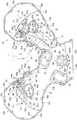
図1を参照すると、内燃機関Eは、車両に搭載されるV型の多気筒4ストローク内燃機関であり、機関本体側部材としての機関本体Eaと、機関本体Eaの、軸方向Aでの一方の端部を覆うチェーンカバー40とを備える。伝動カバーとしてのチェーンカバー40は、機関本体Eaに着脱可能に結合されるカバー体である。
Hereinafter, embodiments of the present invention will be described with reference to FIGS.
Referring to FIG. 1, an internal combustion engine E is a V-type multi-cylinder four-stroke internal combustion engine mounted on a vehicle, and one of an engine body Ea as an engine body side member and an engine body Ea in the axial direction A. And a chain cover 40 that covers the end of each. The chain cover 40 as a transmission cover is a cover body that is detachably coupled to the engine body Ea.

機関本体Eaは、V字形の1対のバンクb1,b2を構成するように配列された複数のシリンダ(図3には、バンクb1の1つのシリンダ26が示されている。)を有するシリンダブロック1と、第1,第2バンクb1,b2のそれぞれにおいてシリンダ26の上端部に結合される1対のシリンダヘッド2,102 および各シリンダヘッド2,102 の上端部に結合される1対のシリンダヘッドカバー5と、シリンダブロック1の下端部に結合されるロアブロック3と、ロアブロック3の下端部に結合されるオイルパン4とから構成される。
シリンダブロック1の下部1c、ロアブロック3およびオイルパン4は、内燃機関Eに備えられる回転軸としてのクランク軸6が配置されるクランク室を形成するクランクケースを構成し、該クランク軸6はシリンダブロック1の下部1cおよびロアブロック3に回転可能に支持される。ここで、下部1cとは、シリンダ軸線方向で各シリンダ26のシリンダボア26a(図3参照)よりも、クランク軸6寄りの部分である。
The engine body Ea has a cylinder block having a plurality of cylinders (one cylinder 26 of the bank b1 is shown in FIG. 3) arranged to form a pair of V-shaped banks b1 and b2. 1 and a pair of cylinder heads 2,102 coupled to the upper end of the cylinder 26 in each of the first and second banks b1, b2 and a pair of cylinders coupled to the upper end of each cylinder head 2,102 The head cover 5 includes a lower block 3 coupled to the lower end portion of the cylinder block 1, and an oil pan 4 coupled to the lower end portion of the lower block 3.
The lower part 1c of the cylinder block 1, the lower block 3 and the oil pan 4 constitute a crankcase forming a crank chamber in which a crankshaft 6 as a rotating shaft provided in the internal combustion engine E is disposed. The crankshaft 6 is a cylinder. The lower part 1c of the block 1 and the lower block 3 are rotatably supported. Here, the lower portion 1c is a portion closer to the crankshaft 6 than the cylinder bore 26a (see FIG. 3) of each cylinder 26 in the cylinder axial direction.

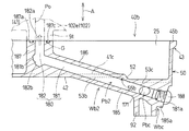
なお、明細書および特許請求の範囲において、クランク軸6の軸方向A(図2参照)は、クランク軸6の回転中心線LCの方向である。また、実施形態において、上下方向は、クランク軸6の回転中心線LCが水平面に含まれるとしたときの鉛直方向であるとする。
そして、側方向は、軸方向Aから見て前記シリンダのシリンダ軸線の方向(以下、「シリンダ軸線方向」という。)に直交する方向であるとする。
In the specification and claims, the axial direction A (see FIG. 2) of the crankshaft 6 is the direction of the rotation center line LC of the crankshaft 6. In the embodiment, the vertical direction is a vertical direction when the rotation center line LC of the crankshaft 6 is included in the horizontal plane.
The lateral direction is assumed to be a direction orthogonal to the direction of the cylinder axis of the cylinder (hereinafter referred to as “cylinder axis direction”) when viewed from the axial direction A.

図3を併せて参照すると、各シリンダ26の前記シリンダボア26aにはピストン27が摺動可能に嵌合する。各バンクb1,b2のシリンダヘッド2,102 には、シリンダ軸線方向でピストン27との間に形成される燃焼室28に連通する吸気ポートおよび排気ポートをそれぞれ開閉する吸気弁および排気弁と、該吸気弁および該排気弁をクランク軸6の回転位置に応じて開閉する動弁装置とが設けられる。
各シリンダヘッド2,102 において、前記吸気ポートの入口が開口する側壁には、吸入空気を該吸気ポートに導く吸気マニホルドNaを有する吸気装置Nが接続され、前記排気ポートの出口が開口する側壁には、燃焼室28から前記排気ポートを経て排出された排気ガスが導かれる排気マニホルドHaを有する排気装置Hが接続される。それゆえ、軸方向Aから見て、1対のバンクb1,b2により形成されるバンク空間8に配置される吸気装置Nは1対のバンクb1,b2の内側に配置され、排気装置Hは1対のバンクb1,b2の外側に配置される。各バンクb1,b2においては、軸方向Aから見て、前記側方向でシリンダ軸線Lyを挟んで配置される吸気装置Nおよび排気装置Hが、それぞれ吸気側および排気側でシリンダヘッド2,102 に接続される。
そして、ピストン27は、前記各燃焼室内での燃料の燃焼により発生する燃焼ガスの圧力により駆動されて往復運動し、コンロッド29を介してクランク軸6を回転方向R(図3参照)に回転駆動する。
ここで、吸気側および排気側は、軸方向Aから見て、シリンダ軸線Lyに対して、吸気装置Nがシリンダヘッド2,102 に接続される側および排気装置Hがシリンダヘッド2,102 に接続される側をそれぞれ意味する。そして、吸気側および排気側の一方を一側とするとき、吸気側および排気側の他方は他側である。
Referring also to FIG. 3, a piston 27 is slidably fitted in the cylinder bore 26a of each cylinder 26. The cylinder heads 2 and 102 of the banks b1 and b2 respectively include an intake valve and an exhaust valve that open and close an intake port and an exhaust port communicating with the combustion chamber 28 formed between the piston 27 in the cylinder axial direction, A valve operating device that opens and closes the intake valve and the exhaust valve according to the rotational position of the crankshaft 6 is provided.
In each cylinder head 2, 102, an intake device N having an intake manifold Na that guides intake air to the intake port is connected to a side wall where the intake port of the intake port is open, and an outlet of the exhaust port is open to the side wall of the cylinder head 2, 102. Is connected to an exhaust device H having an exhaust manifold Ha through which exhaust gas discharged from the combustion chamber 28 through the exhaust port is guided. Therefore, when viewed from the axial direction A, the intake device N arranged in the bank space 8 formed by the pair of banks b1 and b2 is arranged inside the pair of banks b1 and b2, and the exhaust device H is 1 Arranged outside the pair of banks b1 and b2. In each of the banks b1 and b2, when viewed from the axial direction A, the intake device N and the exhaust device H arranged with the cylinder axis Ly sandwiched in the lateral direction are connected to the cylinder heads 2, 102 on the intake side and the exhaust side, respectively. Connected.
The piston 27 is driven by the pressure of the combustion gas generated by the combustion of the fuel in each combustion chamber to reciprocate, and the crankshaft 6 is rotationally driven in the rotational direction R (see FIG. 3) via the connecting rod 29. To do.
Here, when viewed from the axial direction A, the intake side and the exhaust side are connected to the cylinder head 2,102 and the exhaust device H is connected to the cylinder head 2,102 with respect to the cylinder axis Ly. Each side is meant. When one of the intake side and the exhaust side is set as one side, the other of the intake side and the exhaust side is the other side.

各シリンダヘッド2,102 とシリンダヘッドカバー5とが協働して形成するヘッド側空間としての動弁室内に配置される前記各動弁装置は、シリンダヘッド2,102 に回転可能に支持される吸気カム軸10および排気カム軸11と、吸気ロッカアームおよび排気ロッカアームと、前記吸気弁および前記排気弁のバルブリフト量特性および開閉時期であるバルブ作動特性を変更可能な作動特性可変機構とを備える可変動弁装置である。そして、吸気カム軸10および排気カム軸11にそれぞれ設けられる吸気カムおよび排気カムは、それぞれ、前記吸気ロッカアームおよび前記排気ロッカアームを介して前記吸気弁および前記排気弁を開閉する。
また、前記作動特性可変機構は、作動形態が異なる複数のロッカアームから構成される前記吸気ロッカアームおよび前記排気ロッカアームにおいてバルブリフト量特性を変更するために前記複数のロッカアームの連結および連結解除が可能な連結切換機構を備えるバルブリフト量制御機構(図示されず)と、クランク軸6の位相に対する吸気カム軸10および排気カム軸11の位相をそれぞれ変更して前記吸気弁および前記排気弁の開閉時期を変更するために後述する各被動スプロケット21,22と各カム軸10,11との相対的な回転位置を変更する位相制御機構12,13とから構成される。
Each valve operating device disposed in a valve operating chamber as a head side space formed by the cooperation of each cylinder head 2, 102 and the cylinder head cover 5 is an intake air that is rotatably supported by the cylinder head 2, 102. Variable movement comprising a camshaft 10 and an exhaust camshaft 11, an intake rocker arm and an exhaust rocker arm, and an operation characteristic variable mechanism capable of changing a valve lift characteristic of the intake valve and the exhaust valve and a valve operation characteristic that is an opening / closing timing It is a valve device. The intake cam and the exhaust cam provided on the intake cam shaft 10 and the exhaust cam shaft 11 respectively open and close the intake valve and the exhaust valve via the intake rocker arm and the exhaust rocker arm, respectively.
Further, the operating characteristic variable mechanism is a connection capable of connecting and disconnecting the plurality of rocker arms in order to change valve lift amount characteristics in the intake rocker arm and the exhaust rocker arm composed of a plurality of rocker arms having different operation forms. A valve lift amount control mechanism (not shown) having a switching mechanism and the phases of the intake camshaft 10 and the exhaust camshaft 11 with respect to the phase of the crankshaft 6 are changed to change the opening / closing timing of the intake valve and the exhaust valve. In order to achieve this, it is composed of phase control mechanisms 12 and 13 for changing the relative rotational positions of the driven sprockets 21 and 22 and the camshafts 10 and 11 to be described later.

前記バルブリフト量制御機構および位相制御機構12,13は、内燃機関Eのオイルポンプ7(図3参照)から吐出されたオイルを作動油とする油圧式の機構であり、内燃機関Eに備えられる部品であるスプール弁からなる油圧制御弁14〜16(図1には、位相制御機構12,13をそれぞれ制御する油圧制御弁14.15が示され、図3には、前記バルブリフト量制御機構を制御する油圧制御弁16が模式的に示されている。)を備える油圧制御機構により制御される。油圧制御弁14,15は、後述する窓部60,160 内に配置または挿入され、シリンダヘッド2,102 に設けられる装着部である装着孔17,18(図4,図11参照)に挿入された状態で、ボルトによりシリンダヘッド2,102 に着脱可能に取り付けられる。また、油圧制御弁16もシリンダヘッド2,102 に取り付けられる。   The valve lift amount control mechanism and the phase control mechanisms 12 and 13 are hydraulic mechanisms that use oil discharged from the oil pump 7 (see FIG. 3) of the internal combustion engine E as a working oil, and are provided in the internal combustion engine E. Hydraulic control valves 14 to 16 comprising spool valves as parts (FIG. 1 shows hydraulic control valves 14.15 for controlling the phase control mechanisms 12 and 13, respectively. FIG. 3 shows the valve lift amount control mechanism. A hydraulic control valve 16 for controlling the pressure is schematically shown.) Is controlled by a hydraulic control mechanism. The hydraulic control valves 14 and 15 are disposed or inserted in window portions 60 and 160, which will be described later, and are inserted into mounting holes 17 and 18 (see FIGS. 4 and 11) which are mounting portions provided in the cylinder head 2 and 102. In this state, it is detachably attached to the cylinder head 2 102 with a bolt. A hydraulic control valve 16 is also attached to the cylinder head 2, 102.

各カム軸10,11は、内燃機関Eに備えられる部品としての動弁用伝動機構T1,T2を介して伝達されるクランク軸6のトルクにより回転駆動される。伝動機構T1,T2は、クランク軸6に設けられた駆動回転体である駆動スプロケット20,120 と、両カム軸10,11に位相制御機構12,13を介して設けられた被動回転体である被動スプロケット21,22と、これらスプロケット20,120 ;21,22に掛け渡されて駆動スプロケット20;120 のトルクを各被動スプロケット21,22に伝達する無端伝動帯である無端のチェーン23;123 と、チェーン23,123 に張力を付与するテンショナ24とを備える巻掛け伝動機構である。テンショナ24は、チェーン23,123 が摺接するテンショナシュー24aと、該テンショナシュー24aをチェーン23,123 に押し付けるテンショナリフタ24bとを備える。   The camshafts 10 and 11 are rotationally driven by the torque of the crankshaft 6 that is transmitted via valve gear transmission mechanisms T1 and T2 as components provided in the internal combustion engine E. The transmission mechanisms T1 and T2 are driven sprockets 20 and 120, which are driving rotary bodies provided on the crankshaft 6, and driven rotary bodies provided on both camshafts 10 and 11 via phase control mechanisms 12 and 13, respectively. Driven sprockets 21, 22 and endless chains 23; 123, which are endless transmission belts that are transmitted to the driven sprockets 21, 22 by being passed over the sprockets 20, 120; The winding transmission mechanism includes a tensioner 24 that applies tension to the chains 23 and 123. The tensioner 24 includes a tensioner shoe 24a in which the chains 23 and 123 are in sliding contact with each other, and a tensioner lifter 24b that presses the tensioner shoe 24a against the chains 23 and 123.

伝動機構T1,T2は、シリンダブロック1、シリンダヘッド2,102 、ロアブロック3、オイルパン4およびシリンダヘッドカバー5のそれぞれの、軸方向Aでの一方の端部1e,2e,102e,3e,4e,5eに結合されるチェーンカバー40と、端部1e,2e,102e,3e,5eとの協働により形成されるチェーン室25(図6〜図9も参照)内に配置される。
そして、チェーンカバー40を境にして、伝動機構T1,T2が配置されるチェーンカバー40の内側に対して、チェーンカバー40の外側には、軸方向Aでチェーンカバー40に隣接して、内燃機関Eに備えられる1以上の補機をクランク軸6のトルクにより駆動するための補機駆動用伝動機構T3が配置される。
伝動機構T3は、クランク軸6の軸端部6eに設けられる駆動プーリ30と、シリンダブロック1およびロアブロック3にブラケットを介して取り付けられる交流発電機および空調用コンプレッサをそれぞれ回転駆動する発電機用被動プーリ31およびコンプレッサ用被動プーリ32と、内燃機関Eを冷却する冷却水を圧送する冷却水ポンプを回転駆動する冷却水ポンプ用被動プーリ33と、アイドルプーリ34と、これらプーリ30〜34に掛け渡された無端のベルト35と、ベルト35に張力を付与するテンショナ36とを備える。テンショナ36は、ベルト35が巻き掛けられるテンショナプーリ36aと、ベルト35を押圧する押圧部であるテンショナプーリ36aを回転可能に支持すると共にシリンダブロック1に揺動可能に支持される支持部材である支持アーム36bとを備える。支持アーム36bは、ベルト35の張力をほぼ一定に維持するように、ベルト35の張力に応じて揺動中心線Lp(図1参照)を中心に揺動する。
The transmission mechanisms T1 and T2 include one end portions 1e, 2e, 102e, 3e, and 4e in the axial direction A of the cylinder block 1, the cylinder heads 2,102, the lower block 3, the oil pan 4, and the cylinder head cover 5, respectively. , 5e and a chain chamber 25 (see also FIGS. 6 to 9) formed by the cooperation of the end portions 1e, 2e, 102e, 3e and 5e.
The internal combustion engine is adjacent to the chain cover 40 in the axial direction A on the outer side of the chain cover 40 with respect to the inner side of the chain cover 40 where the transmission mechanisms T1 and T2 are arranged with the chain cover 40 as a boundary. An auxiliary machine drive transmission mechanism T3 for driving one or more auxiliary machines included in E by the torque of the crankshaft 6 is arranged.
The transmission mechanism T3 is for a generator that rotationally drives a drive pulley 30 provided at the shaft end 6e of the crankshaft 6, an AC generator and an air conditioning compressor that are attached to the cylinder block 1 and the lower block 3 via brackets. The driven pulley 31 and the driven pulley 32 for the compressor, the driven pulley 33 for the cooling water pump that rotationally drives the cooling water pump that pumps the cooling water that cools the internal combustion engine E, the idle pulley 34, and the pulleys 30 to 34 are hung. The passed endless belt 35 and a tensioner 36 that applies tension to the belt 35 are provided. The tensioner 36 is a support member that rotatably supports a tensioner pulley 36a around which the belt 35 is wound and a tensioner pulley 36a that is a pressing portion that presses the belt 35, and is supported by the cylinder block 1 so as to be swingable. Arm 36b. The support arm 36b swings about the swing center line Lp (see FIG. 1) according to the tension of the belt 35 so as to maintain the tension of the belt 35 substantially constant.

図1〜図4を参照すると、各端部1e,2e,102e,3e,4e,5eに結合されるチェーンカバー40は、形成材料である金属材料としてのアルミニウム合金から鋳造により成形された単一の成形品であり、両バンクb1,b2に対応して、軸方向Aから見てV字形を形成する1対の第1,第2バンク部40a,40bを有する。
そして、チェーンカバー40は、内面41および外面42から構成される表面と、各端部1e,2e,102e,3e,4e,5eに一体成形されて設けられる帯状の結合座9a,9b(図1には、オイルパン4における結合座9aが示され、図6,図8には、シリンダブロック1の端部1eにおける結合座9bが示されている。)に結合される外縁部43と、該外縁部43の内周側に位置すると共に端部1e,2e,102e,3eをロアブロック3からシリンダブロック1を経てシリンダヘッド2,102 に渡って軸方向Aから覆う被覆部としての壁部50とを有する。
壁部50は、所定方向としての軸方向Aでシリンダブロック1、シリンダヘッド2,102 およびロアブロック3の各端部1e,2e,102e,3eと対向して配置されて、それら端部1e,2e,102e,3eおよびシリンダヘッドカバー5の端部5eと協働して内空間としての伝動室であるチェーン室25を形成する。
1 to 4, a chain cover 40 coupled to each end 1e, 2e, 102e, 3e, 4e, 5e is a single unit formed by casting from an aluminum alloy as a metal material as a forming material. And a pair of first and second bank portions 40a, 40b that form a V shape when viewed from the axial direction A, corresponding to both banks b1, b2.
The chain cover 40 has a surface composed of an inner surface 41 and an outer surface 42, and strip-shaped coupling seats 9a, 9b (FIG. 1) provided integrally with the end portions 1e, 2e, 102e, 3e, 4e, 5e. Shows a coupling seat 9a in the oil pan 4, and FIGS. 6 and 8 show a coupling seat 9b in the end 1e of the cylinder block 1.) A wall portion 50 serving as a covering portion that is located on the inner peripheral side of the outer edge portion 43 and covers the end portions 1e, 2e, 102e, 3e from the lower block 3 through the cylinder block 1 to the cylinder head 2,102 from the axial direction A. And have.
The wall portion 50 is disposed so as to face the end portions 1e, 2e, 102e, and 3e of the cylinder block 1, the cylinder heads 2, 102, and the lower block 3 in the axial direction A as a predetermined direction. 2e, 102e, 3e and the end 5e of the cylinder head cover 5 cooperate with each other to form a chain chamber 25 as a transmission chamber as an inner space.

外縁部43は、結合座9a,9bに対応して帯状に延びていて結合座9a,9bに合わせられる合わせ面45a,45bを有する合わせ部44a,44bと、合わせ部44bから軸方向Aに立ち上がる立上がり壁部44c(図7も参照)と、合わせ部44a,44bの外周側に位置する1対のカバー側当接部77,177 とを有する。
合わせ部44a,44bは、オイルパン4の結合座9aに上下方向で合わせられる合わせ面45aを有する合わせ部44aと、結合座9bに軸方向Aで合わせられる合わせ面45bを有する合わせ部44bとから構成される。そして、合わせ部44a,44bは、外縁部43に沿って間隔をおいて配置された複数の結合部としての結合ボス部46a,46bを有する。結合座9aに結合される結合ボス部46aには結合具としてのボルトB1がねじ込まれるネジ孔が設けられ、結合座9bに結合される結合ボス部46bには結合具としてのボルトB2が挿通される挿通孔46hが設けられる。
このため、外縁部43は結合ボス部46a,46bにおいてボルトB1,B2が結合座9a,9bにねじ込まれて締結される。また、合わせ面45a,45bは、結合座9a,9bとの間を密封するシール面でもある。それゆえ、合わせ部44a,44bは、各端部1e,2e,102e,3e,4e,5eとの間を密封するシール部である。なお、合わせ面45a,45bには、シール部材としての液状シール材が塗布されて、結合座9a,9bと合わせ部44a,44bとの間がシールされる。
各当接部77,177 は、後述するカバー側油路Pa,Pbの通路壁Wa1,Wb1を構成し、シリンダブロック1に設けられた当接部9m,9n(図6,図8参照)に当接する当接面77a,177a(図4参照)を有する。
The outer edge portion 43 extends in a strip shape corresponding to the coupling seats 9a and 9b and has mating portions 44a and 44b having mating surfaces 45a and 45b mated with the coupling seats 9a and 9b, and rises in the axial direction A from the mating portion 44b. It has a rising wall portion 44c (see also FIG. 7) and a pair of cover side contact portions 77, 177 located on the outer peripheral side of the mating portions 44a, 44b.
The mating portions 44a and 44b are composed of a mating portion 44a having a mating surface 45a that is mated in the vertical direction with the coupling seat 9a of the oil pan 4, and a mating portion 44b having a mating surface 45b mating with the coupling seat 9b in the axial direction A. Composed. The mating portions 44 a and 44 b have coupling boss portions 46 a and 46 b as a plurality of coupling portions arranged at intervals along the outer edge portion 43. The coupling boss 46a coupled to the coupling seat 9a is provided with a screw hole into which a bolt B1 serving as a coupling tool is screwed, and the bolt B2 serving as a coupling tool is inserted into the coupling boss 46b coupled to the coupling seat 9b. An insertion hole 46h is provided.
For this reason, the outer edge portion 43 is fastened by bolts B1 and B2 screwed into the coupling seats 9a and 9b at the coupling boss portions 46a and 46b. In addition, the mating surfaces 45a and 45b are also sealing surfaces that seal between the coupling seats 9a and 9b. Therefore, the mating portions 44a and 44b are seal portions that seal between the end portions 1e, 2e, 102e, 3e, 4e, and 5e. A liquid sealing material as a sealing member is applied to the mating surfaces 45a and 45b, and the space between the coupling seats 9a and 9b and the mating portions 44a and 44b is sealed.
The contact portions 77 and 177 constitute passage walls Wa1 and Wb1 of cover-side oil passages Pa and Pb, which will be described later, and contact portions 9m and 9n provided in the cylinder block 1 (see FIGS. 6 and 8). Contact surfaces 77a and 177a (see FIG. 4) that contact each other are provided.

チェーンカバー40の表面を構成する内面41は、外縁部43および壁部50のチェーン室25に対面する内壁面41cと、上下方向で端部4eに対向する合わせ面45aと、軸方向Aで端部1e,2e,102e,3e,5eに対向する合わせ面45bと、後述する周壁61,161の合わせ面63,163 と、当接面77a,177aと、後述するカバー側当接部87,187 の当接面87a,187aとを含む。また、チェーンカバー40の表面を構成する外面42は、チェーンカバー40を境にして、チェーン室25とは反対側の空間である外空間に対面する面である。
そして、各合わせ面45b,63,163 、各当接面77a,177a,87a,187aは、この実施形態では軸方向Aに直交する同一の平面上に位置するが、別の例として、軸方向Aに交差すると共に互いに平行な複数の平面上、または軸方向Aに直交以外の態様で交差する同一の平面上に位置していてもよい。
ここで、結合座9a,9bへのチェーンカバー40の取付方向は、合わせ面45bに直交する方向または軸方向Aであるとする。
The inner surface 41 constituting the surface of the chain cover 40 has an inner wall surface 41c facing the chain chamber 25 of the outer edge portion 43 and the wall portion 50, a mating surface 45a facing the end portion 4e in the vertical direction, and an end in the axial direction A. The mating surface 45b facing the portions 1e, 2e, 102e, 3e, 5e, mating surfaces 63, 163 of the peripheral walls 61, 161 described later, contact surfaces 77a, 177a, and cover side contact portions 87, 187 described later Contact surfaces 87a and 187a. Further, the outer surface 42 constituting the surface of the chain cover 40 is a surface facing the outer space which is the space opposite to the chain chamber 25 with the chain cover 40 as a boundary.
The mating surfaces 45b, 63, 163 and the contact surfaces 77a, 177a, 87a, 187a are located on the same plane orthogonal to the axial direction A in this embodiment, but as another example, the axial direction They may be located on a plurality of planes that intersect A and parallel to each other, or on the same plane that intersects the axial direction A in a manner other than orthogonal.
Here, it is assumed that the attaching direction of the chain cover 40 to the coupling seats 9a and 9b is a direction orthogonal to the mating surface 45b or an axial direction A.

端部1e,2e,102e,3e,5eおよび伝動機構T1,T2を軸方向Aで外側から覆う壁部50は、該壁部50を軸方向Aに貫通する空間である窓部60,160 ,66,69を形成する環状の周壁61,161 ,65,68と、各バンク部40a,40bに配置されてカバー側油路Pa,Pbを形成する通路壁Wa1,Wa2,Wb1,Wb2(図14〜図17も参照)と、各バンクb1,b2に配置されてチェーンカバー40に取り付けられる被取付部品としてのエンジンハンガ93(図1参照)が取り付けられる取付座91,92と、壁部50を軸方向Aでの段部55a,55bを有する壁とするための段差部51,52と、壁部50の剛性を高めて壁部50の膜面振動を抑制するための多数のリブ58a,58b,58cとを有する。   The wall portion 50 that covers the end portions 1e, 2e, 102e, 3e, 5e and the transmission mechanisms T1, T2 from the outside in the axial direction A has window portions 60, 160, which are spaces penetrating the wall portion 50 in the axial direction A. Annular peripheral walls 61, 161, 65, 68 forming 66, 69 and passage walls Wa1, Wa2, Wb1, Wb2 (FIG. 14) arranged in the respective bank portions 40a, 40b and forming cover side oil passages Pa, Pb. To FIG. 17), mounting seats 91 and 92 to which engine hangers 93 (see FIG. 1) to be attached to the chain cover 40 and mounted on the banks b1 and b2 are attached, and the wall 50 Step portions 51 and 52 for forming walls having step portions 55a and 55b in the axial direction A, and a plurality of ribs 58a and 58b for increasing the rigidity of the wall portion 50 and suppressing the film surface vibration of the wall portion 50. , 58c.

壁部50は、軸方向Aでの段差部51が形成されることにより、結合座9bまたは合わせ面45bからの軸方向Aでの距離が異なる複数の壁部分である第1被覆部としての低壁部53aと、第2被覆部としての高壁部53b,53cとを有する。高壁部53b,53cは、低壁部53aよりも軸方向Aで端部1e,2e,102e,3e,5eから離隔し、かつ低壁部53aとの間に形成される段差部51を介して段違いに形成される。
合わせ面45bからの距離が低壁部53aよりも大きい高壁部53b,53cは、別の段差部52により形成される第1壁部分としての第1高壁部53bと第2壁部分としての第2高壁部53cとを有する。第2高壁部53cは、合わせ面45bからの距離が該第1高壁部53bよりも大きい。そして、低壁部53aおよび第1,第2高壁部53b,53cは、合わせ面45bにほぼ平行である(または、軸方向Aにほぼ直交する)と共にほぼ平面状であり、壁部50における平面部である。
The wall portion 50 is formed as a step portion 51 in the axial direction A so that the first covering portion is a plurality of wall portions having different distances in the axial direction A from the coupling seat 9b or the mating surface 45b. It has the wall part 53a and the high wall parts 53b and 53c as a 2nd coating | coated part. The high wall portions 53b and 53c are separated from the end portions 1e, 2e, 102e, 3e, and 5e in the axial direction A with respect to the low wall portion 53a, and through a step portion 51 formed between the low wall portions 53a. Are formed in steps.
The high wall portions 53b and 53c whose distance from the mating surface 45b is larger than the low wall portion 53a are the first high wall portion 53b as the first wall portion formed by another stepped portion 52 and the second wall portion. A second high wall portion 53c. The distance from the mating surface 45b of the second high wall portion 53c is greater than that of the first high wall portion 53b. The low wall portion 53a and the first and second high wall portions 53b and 53c are substantially parallel to the mating surface 45b (or substantially perpendicular to the axial direction A) and substantially planar, It is a plane part.

内壁面41cおよび外面42において段差を形成している段差部51は、第1バンク部40aにおいて、伝動機構T1のチェーン23の弛み側23aの外側に沿いながら、かつバンク空間8寄りまたは吸気側で、シリンダブロック1の下部1cからシリンダヘッド2,102 に渡ってシリンダ軸線方向に延びている。   The step portion 51 forming a step on the inner wall surface 41c and the outer surface 42 is along the outer side of the slack side 23a of the chain 23 of the transmission mechanism T1 in the first bank portion 40a and on the intake side or near the bank space 8. The cylinder block 1 extends in the cylinder axial direction from the lower part 1c of the cylinder block 1 to the cylinder heads 2,102.

低壁部53aは、第1バンク部40aにおいて、主に排気側に位置し、かつその一部が吸気側のシリンダ軸線Ly寄りに位置して、軸方向Aでチェーン室25を挟んで端部1e,2eと対向すると共に、該端部1e,2eをシリンダブロックの下部1cからシリンダヘッド2に渡って覆うようにシリンダ軸線方向に延びている。図1に示されるように、低壁部53aは、駆動スプロケット20と被動スプロケット21,22との間に位置するチェーン23の部分を軸方向Aで外側から覆う。   In the first bank portion 40a, the low wall portion 53a is located mainly on the exhaust side, and a part of the low wall portion 53a is located near the cylinder axis Ly on the intake side, with the chain chamber 25 being sandwiched in the axial direction A. 1e and 2e are opposed to each other and extend in the cylinder axial direction so as to cover the end portions 1e and 2e from the lower part 1c of the cylinder block to the cylinder head 2. As shown in FIG. 1, the low wall portion 53a covers the portion of the chain 23 located between the driving sprocket 20 and the driven sprockets 21 and 22 from the outside in the axial direction A.

第1高壁部53bは、第1バンク部40aにおいて、主に吸気側に位置して、軸方向Aでチェーン室25を挟んで端部1e,2eと対向すると共に、該端部1e,2eを下部1cからシリンダヘッド2に渡って覆うように、シリンダ軸線方向に延びている。そして、第1バンク部40aにおいて、第1高壁部53bは、軸方向Aから各被動スプロケット21,22の過半および各カム軸10,11を覆う。
また、第1高壁部53bは、第2バンク部40bにおいて、吸気側および排気側のほぼ全範囲で、該端部1e,102eをシリンダブロックの下部1cからシリンダヘッド2,102 に渡って覆うように、シリンダ軸線方向に延びている。
The first high wall portion 53b is located mainly on the intake side in the first bank portion 40a and faces the end portions 1e and 2e across the chain chamber 25 in the axial direction A, and the end portions 1e and 2e. Is extended in the cylinder axial direction so as to cover the cylinder head 2 from the lower part 1c. In the first bank portion 40a, the first high wall portion 53b covers the majority of the driven sprockets 21 and 22 and the cam shafts 10 and 11 from the axial direction A.
The first high wall portion 53b covers the end portions 1e and 102e from the lower portion 1c of the cylinder block to the cylinder heads 2 and 102 in almost the entire range on the intake side and the exhaust side in the second bank portion 40b. Thus, it extends in the cylinder axial direction.

第1バンク部40aの第1高壁部53bは、第1バンク部40aにおいて局部的に軸方向Aに突出している壁であり、チェーン室25において、局部的に、軸方向Aで低壁部53aよりも外側に突出した空間部分である突出空間25aを形成し(図7も参照)、該突出空間25aを含めて軸方向Aで端部1e,2eとの間に、チェーン室25の一部として、ブリーザ通路54を形成する。それゆえ、ブリーザ通路54は、突出空間25aの分だけ軸方向幅が大きくされている。
ブリーザ通路54は、前記クランク室内のブローバイガスをシリンダヘッド2により形成される前記動弁室に導くために、該クランク室と該動弁室とを連通させる連通路である。
そして、該動弁室内に導かれたブローバイガスは、前記動弁室内に設けられた気液分離器を通過した後、吸気装置Nに導かれて吸入空気と混合されて、燃焼室28に吸入される。
The first high wall portion 53b of the first bank portion 40a is a wall that locally protrudes in the axial direction A in the first bank portion 40a, and the low wall portion in the axial direction A locally in the chain chamber 25. A protruding space 25a, which is a space portion protruding outward from 53a, is formed (see also FIG. 7), and the chain chamber 25 is provided between the ends 1e and 2e in the axial direction A including the protruding space 25a. As a part, a breather passage 54 is formed. Therefore, the breather passage 54 has a larger axial width by the protruding space 25a.
The breather passage 54 is a communication passage that communicates the crank chamber with the valve chamber in order to guide the blow-by gas in the crank chamber to the valve chamber formed by the cylinder head 2.
Then, the blow-by gas introduced into the valve operating chamber passes through the gas-liquid separator provided in the valve operating chamber, and then is guided to the intake device N to be mixed with the intake air and sucked into the combustion chamber 28. Is done.

第1バンク部40aでの壁部50において、第1高壁部53bおよびブリーザ通路54は、外縁部43のうちの、前記側方向でシリンダ軸線Lyを挟む吸気側の側縁部43iと排気側の側縁部43eとの間に形成され、この実施形態では、バンク空間8寄りに位置する側縁部43iに前記側方向で隣接すると共に、側縁部43eよりも上方に位置する該側縁部43iに沿ってシリンダ軸線方向に延びている。
このため、突出空間25aは、第1高壁部53bと段差部51と側縁部43iの立上がり壁部44cとにより形成される(図7参照)。また、ブリーザ通路43はバンク空間8寄りに位置することから、排気マニホルドHaに近い側縁部43eから、より遠方にあるために、ブリーザ通路54を流通するブローバイガスが排気マニホルドNaの高熱の影響を受けにくい。
また、第1高壁部53bは低壁部53aよりも上方側に位置し、ブリーザ通路54はチェーン室25の上端の空間部分を構成することから、チェーン室25内のオイルの大部分は、チェーン室25において軸方向Aで端部1e,2eと低壁部53aとの間に形成される下部空間で流動するので、チェーン室25内のオイルがブリーザ通路54に流入することが抑制される。
In the wall portion 50 of the first bank portion 40a, the first high wall portion 53b and the breather passage 54 are, on the outer edge portion 43, the side edge portion 43i on the intake side sandwiching the cylinder axis Ly in the side direction and the exhaust side. In this embodiment, the side edge is adjacent to the side edge 43i located near the bank space 8 in the lateral direction and is located above the side edge 43e. It extends in the cylinder axis direction along the portion 43i.
Therefore, the protruding space 25a is formed by the first high wall portion 53b, the stepped portion 51, and the rising wall portion 44c of the side edge portion 43i (see FIG. 7). Further, since the breather passage 43 is located closer to the bank space 8, the blow-by gas flowing through the breather passage 54 is influenced by the high heat of the exhaust manifold Na because the breather passage 43 is further away from the side edge 43e near the exhaust manifold Ha. It is hard to receive.
Further, since the first high wall portion 53b is located above the lower wall portion 53a and the breather passage 54 constitutes a space portion at the upper end of the chain chamber 25, most of the oil in the chain chamber 25 is Since the fluid flows in the lower space formed between the end portions 1e, 2e and the low wall portion 53a in the axial direction A in the chain chamber 25, the oil in the chain chamber 25 is prevented from flowing into the breather passage 54. .

第1バンク1bにおいて、第1高壁部53bおよびブリーザ通路54は、軸方向Aから見て、チェーン23の外側を、その弛み側23aに沿って延びており、かつテンショナシュー24aと重なる位置、およびシリンダボア26aと重なる位置にある。そして、ブリーザ通路54に沿うチェーン23の走行方向が、ブローバイガスが前記動弁室に向かう方向に沿う方向である。   In the first bank 1b, the first high wall portion 53b and the breather passage 54 extend from the outer side of the chain 23 along the slack side 23a when viewed from the axial direction A, and overlap with the tensioner shoe 24a. The cylinder bore 26a overlaps the cylinder bore 26a. The traveling direction of the chain 23 along the breather passage 54 is a direction along the direction in which blow-by gas is directed to the valve operating chamber.

図3〜図5を参照すると、第1高壁部53bは、軸方向Aで端部1eと対向する内壁面41cに形成された突条59を有する。軸方向Aで端部1eに向かって(すなわち内側に向かって)突出する突条59は、軸方向Aから見てシリンダ軸線方向と交差する方向に直線状に延びていて段差部51と側縁部43iの結合ボス部46b1とを連結する。突条59は、上部の接続部である結合ボス部46b1から下部の接続部である段差部51に向かって、下方で、かつシリンダ軸線方向において回転中心線Lcに近づく方向に傾斜している。また、段差部51は、その端部で外縁部43の結合ボス部46bに接続している。
突条59の高さは、内壁面41cから軸方向Aでの端部51aの高さに等しく、該突条59の頂部が低壁部53aの内壁面41cに設けられたリブ58cの頂部と同じ高さとなるように、または段差部51の段差にほぼ等しくなるように設定されている。突条59は、ブリーザ通路54の上流部における通路部分としての入口54aにおいて、第1高壁部53b側から突出空間25aをほぼ塞ぐように延びている。そして、前記クランク室からのブローバイガスは、軸方向Aで突条59と端部1eとの間に形成される該入口54aを通って、ブリーザ通路54に流入する。それゆえ、突条59はブリーザ通路54の入口54aを横切る堰を構成する。
Referring to FIGS. 3 to 5, the first high wall portion 53 b has a protrusion 59 formed on the inner wall surface 41 c facing the end portion 1 e in the axial direction A. The protrusion 59 protruding toward the end 1e in the axial direction A (that is, inward) extends linearly in a direction intersecting the cylinder axial direction when viewed from the axial direction A, and the step portion 51 and the side edge. The connecting boss portion 46b1 of the portion 43i is connected. The ridge 59 is inclined downward from the connecting boss portion 46b1 which is the upper connecting portion toward the step portion 51 which is the lower connecting portion, in a direction approaching the rotation center line Lc in the cylinder axial direction. Further, the step portion 51 is connected to the coupling boss portion 46b of the outer edge portion 43 at the end thereof.
The height of the ridge 59 is equal to the height of the end 51a in the axial direction A from the inner wall surface 41c, and the top of the ridge 59 is the top of the rib 58c provided on the inner wall 41c of the low wall portion 53a. The height is set to be the same or substantially equal to the step of the step portion 51. The protrusion 59 extends from the first high wall portion 53b side so as to substantially block the protruding space 25a at the inlet 54a as a passage portion in the upstream portion of the breather passage 54. The blow-by gas from the crank chamber flows in the breather passage 54 through the inlet 54a formed between the protrusion 59 and the end 1e in the axial direction A. Therefore, the protrusion 59 constitutes a weir that crosses the inlet 54 a of the breather passage 54.

このため、前記クランク室から流出したブローバイガスがブリーザ通路54に流入するとき、その一部が突条59に衝突してブローバイガスに混入しているオイルが突条59に付着して分離される。さらに、ブリーザ通路54の外部で第1高壁部53bの内壁面41cを伝うオイルは、突条59によりブリーザ通路に流入することが阻止または抑制される。そして、分離されたオイルまたは付着したオイルは、ブリーザ通路54よりも上流側で突条59を流下して、内壁面41cを伝ってオイルパン4(図1参照)に戻る。このように、突条59は、ブローバイガス中に混入しているオイルを分離して、ブリーザ通路54を流れるブローバイガスまたは前記動弁室に導かれるブローバイガスに混入しているオイルの量を減少させる機能を有するオイル分離壁である。   For this reason, when blow-by gas flowing out of the crank chamber flows into the breather passage 54, a part of the blow-by gas collides with the ridge 59, and oil mixed in the blow-by gas adheres to the ridge 59 and is separated. . Further, the oil transmitted along the inner wall surface 41c of the first high wall portion 53b outside the breather passage 54 is prevented or suppressed from flowing into the breather passage by the protrusion 59. The separated or attached oil flows down the ridge 59 upstream of the breather passage 54, returns to the oil pan 4 (see FIG. 1) along the inner wall surface 41c. In this way, the protrusion 59 separates the oil mixed in the blow-by gas, and reduces the amount of oil mixed in the blow-by gas flowing through the breather passage 54 or the blow-by gas guided to the valve operating chamber. An oil separation wall having a function of

図1,図3〜図5を参照すると、低壁部53aが設けられることにより、部分的に端部1e,2eの結合座9bからの軸方向Aへの壁部50の突出量が抑えられるので、低壁部53aにより形成されるスペースを利用して、軸方向Aでチェーンカバー40の外側に隣接して配置される部品、この実施形態ではテンショナ36の支持アーム36bが該スペースに配置される。支持アーム36bは、軸方向Aで低壁部53aを挟んで端部1eとは反対側に配置され、軸方向Aで段差部51と少なくとも部分的に重なる位置(または、同じ位置)にある。
また、段差部51は支持アーム36bの移動範囲である揺動範囲の外側に形成される。そして、段差部51における突条59との連結部を含む部分51aは、ブリーザ通路54の入口54a付近の通路面積を突条59が延びる方向で規定する部分である。また、部分51aは、揺動して移動する支持アーム36bがその移動方向としての揺動方向で最も近接する近接部分であり、支持アーム36bの揺動軌跡にほぼ沿う形状に形成される。該部分51aが支持アーム36bの揺動軌跡に沿う形状に形成されることにより、段差部51に支持アーム36bが近接して配置されるにも拘わらず、入口54aおよび該入口54a付近でのブリーザ通路の通路面積を大きくすることができるので、ブローバイガスのブリーザ通路54への流入を促進することができる。
Referring to FIGS. 1 and 3 to 5, by providing the low wall portion 53 a, the protruding amount of the wall portion 50 in the axial direction A from the coupling seat 9 b of the end portions 1 e and 2 e is partially suppressed. Therefore, by utilizing the space formed by the low wall portion 53a, a part disposed adjacent to the outside of the chain cover 40 in the axial direction A, in this embodiment, the support arm 36b of the tensioner 36 is disposed in the space. The The support arm 36b is disposed on the opposite side of the end portion 1e across the low wall portion 53a in the axial direction A, and is at a position (or the same position) that at least partially overlaps the stepped portion 51 in the axial direction A.
Further, the step portion 51 is formed outside the swinging range that is the moving range of the support arm 36b. A portion 51 a including a connecting portion with the protrusion 59 in the stepped portion 51 is a portion that defines a passage area in the vicinity of the inlet 54 a of the breather passage 54 in a direction in which the protrusion 59 extends. The portion 51a is a proximity portion where the support arm 36b that swings and moves is closest in the swing direction as the moving direction, and is formed in a shape that substantially follows the swing trajectory of the support arm 36b. By forming the portion 51a in a shape that follows the swinging trajectory of the support arm 36b, the breather in the vicinity of the inlet 54a and the inlet 54a despite the support arm 36b being disposed close to the stepped portion 51. Since the passage area of the passage can be increased, the flow of blow-by gas into the breather passage 54 can be promoted.

図1〜図4を参照すると、第2バンク部40bでは、壁部50は主に高壁部53b,53cを有する。そして、軸方向Aで駆動スプロケット20よりも壁部50寄りに配置される駆動スプロケット120 に対応して、第1高壁部53bが、駆動スプロケット120 と被動スプロケット21,22との間に位置するチェーン123 の部分を軸方向Aから覆う。また、第2高壁部53cは、後述する交差壁部Wbcが設けられる部分にあり、さらに軸方向Aから各被動スプロケット21,22の過半および各カム軸10,11を覆う。   1 to 4, in the second bank portion 40b, the wall portion 50 mainly has high wall portions 53b and 53c. The first high wall portion 53b is positioned between the drive sprocket 120 and the driven sprockets 21 and 22 corresponding to the drive sprocket 120 disposed closer to the wall portion 50 than the drive sprocket 20 in the axial direction A. A portion of the chain 123 is covered from the axial direction A. Further, the second high wall portion 53c is in a portion where an intersecting wall portion Wbc described later is provided, and further covers the majority of the driven sprockets 21 and 22 and the cam shafts 10 and 11 from the axial direction A.

併せて図10,図11を参照すると、1対の窓部60,160 をそれぞれ形成する1対の周壁61,161 は、内壁面41cにおいて軸方向Aでシリンダヘッド2,102 の端部2e,102eに向かって突出する突条であり、シリンダヘッド2,102 に一体成形されて設けられると共に結合座9bの内周側に位置する結合座9c,9dに当接する。
第1バンク部40aに配置される周壁61は低壁部53aに形成され、第2バンク部40bに配置される周壁161 は第1高壁部53bに形成されることから、軸方向Aでの周壁161 の高さは、軸方向Aでの周壁61の高さよりも高い。
10 and 11, the pair of peripheral walls 61 and 161 forming the pair of window portions 60 and 160, respectively, are arranged on the inner wall surface 41c in the axial direction A in the end portion 2e of the cylinder head 2,102. The ridge protrudes toward 102e, is integrally formed with the cylinder head 2, 102, and abuts on coupling seats 9c and 9d located on the inner peripheral side of the coupling seat 9b.
The peripheral wall 61 disposed in the first bank portion 40a is formed in the low wall portion 53a, and the peripheral wall 161 disposed in the second bank portion 40b is formed in the first high wall portion 53b. The height of the peripheral wall 161 is higher than the height of the peripheral wall 61 in the axial direction A.

壁部50における開口部である窓部60,160 を形成する開口形成部としての各周壁61,161 は、該周壁61,161 に沿って間隔をおいて設けられる複数としての4つの結合部であるボス部62,162 と、結合座9c,9dに合わせられるシール面である合わせ面63,163 とを有する。
周壁61,161 において壁厚が大きくされた部分であるボス部62,162 は、該ボス部62,162 に設けられた挿通孔62a,162aに挿入され、かつ結合座9c,9dにねじ込まれる結合具であるボルトB3(図1参照)により締結される。それゆえ、周壁61,161 は、ボス部62,162 において結合座9c,9dに結合される。合わせ面63,163 には液状シール材が塗布されてもよい。
そして、各周壁61,161 は、チェーンカバー40が機関本体Eaに取り付けられた状態で油圧制御弁14,15の着脱を可能とするための窓部60,160 を形成するための部分である。
したがって、該窓部60,160 は油圧制御弁14,15の挿入用および取出用の空間である。
Each of the peripheral walls 61 and 161 serving as an opening forming portion for forming the window portions 60 and 160 that are openings in the wall portion 50 is a plurality of four connecting portions provided at intervals along the peripheral walls 61 and 161. There are certain boss portions 62, 162 and mating surfaces 63, 163 which are seal surfaces mated with the coupling seats 9c, 9d.
Boss portions 62 and 162, which are portions of the peripheral walls 61 and 161 where the wall thickness is increased, are inserted into insertion holes 62a and 162a provided in the boss portions 62 and 162, and are coupled into the coupling seats 9c and 9d. It is fastened by a bolt B3 (see FIG. 1) as a tool. Therefore, the peripheral walls 61 and 161 are coupled to the coupling seats 9c and 9d at the boss portions 62 and 162. A liquid sealing material may be applied to the mating surfaces 63 and 163.
The peripheral walls 61 and 161 are portions for forming window portions 60 and 160 for enabling the hydraulic control valves 14 and 15 to be attached and detached with the chain cover 40 attached to the engine body Ea.
Therefore, the window portions 60 and 160 are spaces for inserting and removing the hydraulic control valves 14 and 15.

図12,図13を参照すると、各窓部60,160 には、複数である所定数の、この実施形態では2つの油圧制御弁14,15が配置され、各油圧制御弁14,15は、該所定数と等しい前記作動特性可変機構である2つの位相制御機構12,13(図1参照)を別々に制御する。   Referring to FIGS. 12 and 13, a predetermined number of plural hydraulic control valves 14 and 15 in this embodiment are arranged in each of the windows 60 and 160, and the hydraulic control valves 14 and 15 are The two phase control mechanisms 12, 13 (see FIG. 1), which are the operation characteristic variable mechanisms equal to the predetermined number, are controlled separately.

各油圧制御弁14,15は、その軸線L1,L2がチェーンカバー40および軸方向A(図10,図11参照)でのシリンダヘッド2,102 の端部2e,102e(図10,図11参照)にそれぞれ直交する方向で、または軸方向Aで、チェーンカバー40の窓部60または窓部160に挿入され、さらにシリンダヘッド2,102 の装着孔17または装着孔18(図4,図10,図11参照)に挿入されている。   Each of the hydraulic control valves 14 and 15 has the axis L1 and L2 of the chain cover 40 and the end 2e and 102e of the cylinder head 2 and 102e in the axial direction A (see FIGS. 10 and 11) (see FIGS. 10 and 11). ) In the direction orthogonal to each other or in the axial direction A, and is inserted into the window portion 60 or the window portion 160 of the chain cover 40, and the mounting hole 17 or the mounting hole 18 (see FIGS. 4, 10, 10) of the cylinder head 2, 102. (See FIG. 11).

同一構造の各油圧制御弁14,15は、シリンダヘッド2,102 (図10,図11参照)に取り付けられた状態で、窓部60,160 内に配置される部分として、円柱状の本体部14a,15aと該本体部14a,15aから径方向外方に山形状に突出する取付部14b,15bとを有する。各取付部14b,15bは、本体部14a,15aに連結されていて径方向で本体部14a,15aに近い基部14b1,15b1と、径方向で本体部14a,15aから最も遠い部分を含む先端部14b2,15b2とを有し、本体部14a,15aから径方向で遠ざかるにつれて、その周方向での幅が次第に小さくなる形状である。また、各取付部14b,15bは、シリンダ軸線方向で、本体部14a,15aに対してシリンダ26(図3参照)寄りまたはクランク軸6寄りに配置される(図1参照)。   The hydraulic control valves 14 and 15 having the same structure are attached to the cylinder heads 2 and 102 (see FIGS. 10 and 11), and are arranged in the window portions 60 and 160 as cylindrical portions. 14a and 15a and mounting portions 14b and 15b projecting in a mountain shape radially outward from the main body portions 14a and 15a. Each mounting portion 14b, 15b is connected to the main body portions 14a, 15a and includes a base portion 14b1, 15b1 close to the main body portions 14a, 15a in the radial direction and a tip portion including a portion farthest from the main body portions 14a, 15a in the radial direction. 14b2 and 15b2, and the width in the circumferential direction gradually decreases as the distance from the main body portions 14a and 15a increases in the radial direction. Further, the mounting portions 14b and 15b are arranged closer to the cylinder 26 (see FIG. 3) or closer to the crankshaft 6 (see FIG. 1) than the main body portions 14a and 15a in the cylinder axis direction.

ここで、油圧制御弁14,15の軸線L1,L2は、筒状の本体部14a,15aの中心軸線であり、油圧制御弁14,15がシリンダヘッド2,102 に取り付けられた状態で、軸線L1,L2は軸方向Aに平行である。また、油圧制御弁14,15に関連して、径方向および周方向は、それぞれ、軸線L1,L2を中心とする径方向および周方向であるとする。   Here, the axis lines L1 and L2 of the hydraulic control valves 14 and 15 are the central axis lines of the cylindrical main body portions 14a and 15a, and the axis lines are in a state where the hydraulic control valves 14 and 15 are attached to the cylinder heads 2 and 102. L1 and L2 are parallel to the axial direction A. Further, in relation to the hydraulic control valves 14 and 15, it is assumed that the radial direction and the circumferential direction are a radial direction and a circumferential direction around the axes L1 and L2, respectively.

なお、油圧制御弁14,15が電気式の制御弁である場合、油圧制御弁14,15には、図12,図13に二点鎖線で示されるように、軸方向Aから見たときに本体部14a,15aを挟んで径方向で取付部14b,15bとはほぼ正反対側で本体部14a,15aから径方向外方に突出するコネクタ部14c,15cが設けられる。そして、窓部60,160 毎に、各取付部14b,15bは本体部14a,15aと共に窓部60,160 内に位置する一方、コネクタ部14c,15cは、軸方向A(図10,図11参照)または軸線L1,L2の方向で取付部14b,15bから離れていて、窓部60,160 の外部に位置する。   In the case where the hydraulic control valves 14 and 15 are electric control valves, the hydraulic control valves 14 and 15 are provided on the hydraulic control valves 14 and 15 when viewed from the axial direction A as shown by a two-dot chain line in FIGS. Connector portions 14c and 15c projecting radially outward from the main body portions 14a and 15a are provided on the substantially opposite side of the mounting portions 14b and 15b in the radial direction across the main body portions 14a and 15a. For each of the window portions 60 and 160, the mounting portions 14b and 15b are located in the window portions 60 and 160 together with the main body portions 14a and 15a, while the connector portions 14c and 15c are arranged in the axial direction A (FIGS. 10 and 11). (See Fig. 4) or apart from the mounting portions 14b and 15b in the direction of the axes L1 and L2, and located outside the window portions 60 and 160.

各油圧制御弁14,15は、取付部14b,15bに設けられた挿通孔(図示されず)に挿通される結合具としてのボルトB7がシリンダヘッド2,102 (図10,図11参照)にねじ込まれて、シリンダヘッド2,102 に固定される。ボルトB7で取付部14b,15bとシリンダヘッド2,102 とが結合されることにより、シリンダヘッド2,102 に対して軸線L1,L2を中心とした油圧制御弁14,15の回動が防止される。   Each of the hydraulic control valves 14 and 15 has a bolt B7 as a coupling member inserted into an insertion hole (not shown) provided in the mounting portions 14b and 15b in the cylinder heads 2 and 102 (see FIGS. 10 and 11). It is screwed and fixed to the cylinder head 2,102. By connecting the mounting portions 14b and 15b and the cylinder heads 2 and 102 with the bolt B7, the hydraulic control valves 14 and 15 around the axes L1 and L2 are prevented from rotating with respect to the cylinder heads 2 and 102. The

各窓部60,160 において、シリンダヘッド2,102 に取り付けられた2つの油圧制御弁14,15は、軸線L1,L2同士が互いに平行になるように並設される。この状態で、各油圧制御弁14,15において、取付部14b,15bは、本体部14a,15aの下部に位置する一方、コネクタ部14c,15cは、本体部14a,15aの上部に位置し、特に窓部60に配置される各油圧制御弁14,15については本体部14a,15aの最上部に位置するので、コネクタ部14c,15cへの電線の接続が容易になる。   In each of the windows 60 and 160, the two hydraulic control valves 14 and 15 attached to the cylinder head 2 and 102 are juxtaposed so that the axes L1 and L2 are parallel to each other. In this state, in each of the hydraulic control valves 14 and 15, the mounting portions 14b and 15b are located below the main body portions 14a and 15a, while the connector portions 14c and 15c are located above the main body portions 14a and 15a. In particular, since the hydraulic control valves 14 and 15 arranged in the window 60 are located at the uppermost portions of the main body portions 14a and 15a, it is easy to connect the electric wires to the connector portions 14c and 15c.

図12〜図17を参照すると、各窓部60;160 を形成する周壁61;161 に設けられてボルトB3により締結される4つのボス部62B,62C,62D,62E;162B,162C,162D,162Eのうちで、2つの第1ボス部であるボス部62B,62C;162B,162Cは、窓部60;160 を挟んで対向する位置にあると共に、互いに近づく方向に窓部60;160 の内側に突出している突出部62B1,62C1;162B1 ,162C1 (図10,図11も参照)を有する。
このため、窓部60;160 は、1対のボス部62B,62C;162B,162Cが2つの油圧制御弁14,15の間で内側に突出することにより、各ボス部62B,62C;162B,162Cによりそれぞれ形成される1対の括れ部60c1,60c2;160c1 ,160c2 (図10,図11も参照)を有する。ボス部62C;160Cの、窓部60;160 の内側への突出量は、ボス部62B;162Bの、窓部60;160 の内側への突出量よりも大きい。
12 to 17, four boss portions 62B, 62C, 62D, 62E; 162B, 162C, 162D, which are provided on the peripheral wall 61; 161 forming each window portion 60; 160 and are fastened by a bolt B3. Of the 162E, the two first boss portions 62B, 62C; 162B, 162C are located at positions facing each other with the window portion 60; 160 in between, and inside the window portion 60; 160 in a direction approaching each other. Projecting portions 62B1, 62C1; 162B1, 162C1 (see also FIGS. 10 and 11).
For this reason, the window portion 60; 160 has a pair of boss portions 62B, 62C; 162B, 162C projecting inward between the two hydraulic control valves 14, 15, so that each boss portion 62B, 62C; 162B, It has a pair of constricted portions 60c1, 60c2; 160c1, 160c2 (see also FIGS. 10 and 11) formed by 162C. The amount of protrusion of the boss portion 62C; 160C toward the inside of the window portion 60; 160 is larger than the amount of protrusion of the boss portion 62B; 162B toward the inside of the window portion 60; 160.

各周壁61;161 において、2つのボス部62B,62C;162B,162Cは、軸方向A(図10,図11も参照)に平行な平面であって両ボス部62B,62C;162B,162Cまたはその挿通孔62ab,62ac;162ab ,162ac と交わる(または、両ボス部62B,62C;162B,162Cまたは両挿通孔62ab,62ac;162ab ,162ac を通る)平面P1;P2(図12,図13参照)により、窓部60,160 が2つの収容空間60a,60b;160a,160bに分割されるように配置される。平面P1;P2は括れ部60c1,60c2;160c1 ,160c2 と交わる(または、括れ部60c1,60c2;160c1 ,160c2 を通る)位置にある。
それゆえ、各窓部60,160 は、軸方向Aから見たときに、1対のボス部62B,62C;162B,162Cまたは1対の括れ部60c1,60c2;160c1 ,160c2 を通る直線または平面P1;P2を境に、第1,第2収容空間60a,60b;160a,160bに分けられる。
In each peripheral wall 61; 161, the two boss portions 62B, 62C; 162B, 162C are planes parallel to the axial direction A (see also FIGS. 10 and 11), and both the boss portions 62B, 62C; 162B, 162C or Plane P1; P2 (see FIGS. 12 and 13) intersecting with the insertion holes 62ab, 62ac; 162ab, 162ac (or both boss portions 62B, 62C; 162B, 162C or both insertion holes 62ab, 62ac; 162ab, 162ac) ), The window portions 60 and 160 are arranged so as to be divided into two accommodating spaces 60a and 60b; 160a and 160b. The planes P1 and P2 intersect with the constricted portions 60c1 and 60c2; 160c1 and 160c2 (or pass through the constricted portions 60c1 and 60c2; 160c1 and 160c2).
Therefore, each window portion 60, 160 is a straight line or plane passing through the pair of boss portions 62B, 62C; 162B, 162C or the pair of constricted portions 60c1, 60c2; 160c1, 160c2 when viewed from the axial direction A. It is divided into first and second accommodation spaces 60a, 60b; 160a, 160b with P1; P2 as a boundary.

そして、1つの油圧制御弁14,15の本体部14a,15aと取付部14b,15bとを合わせた全体またはほぼ該全体が1つの収容空間60a,60b;160a,160bに収容されるように、第1,第2油圧制御弁14,15が、各窓部60;160 内で、第1,第2収容空間60a,60b;160a,160bにそれぞれ配置される。なお、図12,図13に示された平面P1;P2は、軸方向Aに平行であると共に両ボス部62B,62C;162B,162Cまたは挿通孔62ab,62ac;162ab ,162ac と交わる多数の平面の一例である。   Then, the whole or almost the whole of the main body portions 14a, 15a and the mounting portions 14b, 15b of one hydraulic control valve 14, 15 is accommodated in one accommodating space 60a, 60b; 160a, 160b. The first and second hydraulic control valves 14 and 15 are disposed in the first and second accommodation spaces 60a and 60b; 160a and 160b, respectively, in the window portions 60 and 160. In addition, plane P1; P2 shown by FIG. 12, FIG. 13 is parallel to the axial direction A, and many planes which cross | intersect both boss | hub parts 62B, 62C; 162B, 162C or insertion hole 62ab, 62ac; 162ab, 162ac It is an example.

各周壁61;161 は、平面P1;P2により2つの第1,第2周壁部分61a,61b;161a,161bに分割される。そして、各周壁61;161 において、2つのボス部62B,62C;162B,162C以外の残りの第2ボス部である複数としての2つのボス部62D,62E;162D,162Eは、各周壁部分61a,61b;161a,161bに1つずつ位置する。また、2つのボス部62D,62E;162D,162Eは、平面P1;P2に直交する方向での各窓部60;160 の最大幅またはほぼ最大幅が形成される部位にある。   Each peripheral wall 61; 161 is divided into two first and second peripheral wall portions 61a, 61b; 161a, 161b by planes P1; P2. In each peripheral wall 61; 161, the two boss portions 62D, 62E; 162D, 162E, which are the remaining second boss portions other than the two boss portions 62B, 62C; 162B, 162C, are respectively connected to the peripheral wall portions 61a. , 61b; one each at 161a, 161b. Further, the two boss portions 62D, 62E; 162D, 162E are located at portions where the maximum width or almost maximum width of the window portions 60; 160 in the direction orthogonal to the plane P1; P2 is formed.

それゆえ、周壁61;161 は、少なくとも2つのボス部62B,62C;162B,162Cにおいて、ボルトB3によりシリンダヘッド2;102 に固定され、この実施形態では、さらに別の2つのボス部62D,62E;162D,162Eにおいて、ボルトB3によりシリンダヘッド2,102 に固定される。   Therefore, the peripheral wall 61; 161 is fixed to the cylinder head 2; 102 by the bolt B3 in at least two boss portions 62B, 62C; 162B, 162C, and in this embodiment, another two boss portions 62D, 62E. In 162D and 162E, it is fixed to the cylinder head 2,102 by a bolt B3.

各窓部60;160 において、2つの油圧制御弁14,15の本体部14a,15aおよび取付部14b,15bは平面P1;P2を挟んで配置され、取付部14b,15b同士がボス部62C;162Cおよび括れ部60c2;160c2を挟んで配置されている。また、各窓部60;160 に配置される両油圧制御弁14,15において、取付部14b,15b同士およびコネクタ部14c,15c同士は、軸方向Aから見て軸線L1,L2を通ると共に上下方向に平行または平面P1;P2に平行な直線を基準位置とするとき、軸線L1,L2または本体部14a,15aに対して該基準位置から周方向で同じ位置に配置される。
さらに、各窓部60;160 内の2つの油圧制御弁14,15に関して、本体部14a,15aおよび取付部14b,15bのうちで本体部14a,15a同士が径方向で最も近接して配置され、各本体部14a,15aは、周壁61;161 の、主に上側周壁部分61c;161cに沿って配置され、各取付部14b,15bは、周壁61,161 の、主に下側周壁部分61d;161dに沿って配置される。
そして、各窓部60;160 における両油圧制御弁14,15の本体部14a,15aおよび取付部14b,15bは、1対のボス部62B,62C;162B,162Cにより形成される1対の括れ部60c1,60c2;160c1 ,160c2 を利用して、該窓部60;160 の形状にほぼ合致した状態で、窓部60,160 に挿入されている。
In each window portion 60; 160, the main body portions 14a and 15a and the attachment portions 14b and 15b of the two hydraulic control valves 14 and 15 are arranged across the plane P1; P2, and the attachment portions 14b and 15b are boss portions 62C; 162C and the constricted portion 60c2; Further, in both hydraulic control valves 14 and 15 disposed in the respective window portions 60; 160, the mounting portions 14b and 15b and the connector portions 14c and 15c pass vertically along the axis lines L1 and L2 when viewed from the axial direction A. When a straight line parallel to the direction or plane P1; P2 is set as a reference position, it is arranged at the same position in the circumferential direction from the reference position with respect to the axis lines L1, L2 or the main body portions 14a, 15a.
Further, with respect to the two hydraulic control valves 14 and 15 in each window portion 60; 160, the main body portions 14a and 15a are disposed closest to each other in the radial direction among the main body portions 14a and 15a and the mounting portions 14b and 15b. The main body portions 14a and 15a are arranged mainly along the upper peripheral wall portion 61c; 161c of the peripheral wall 61; 161, and the mounting portions 14b and 15b are mainly lower peripheral wall portions 61d of the peripheral walls 61 and 161. Arranged along 161d.
The main body portions 14a and 15a and the mounting portions 14b and 15b of the hydraulic control valves 14 and 15 in each window portion 60 and 160 are a pair of constrictions formed by a pair of boss portions 62B and 62C; 162B and 162C. The portions 60c1, 60c2; 160c1, 160c2 are used to be inserted into the window portions 60, 160 in a state substantially matching the shape of the window portions 60; 160.

一般に、チェーンカバーに設けられた窓部に、シリンダヘッドに結合される取付部を有する油圧制御弁が配置される内燃機関において、1つの窓部に複数の該油圧制御弁が配置される場合には、窓部の開口面積が大きくなって、チェーンカバーの剛性の低下を招来することがある。そこで、この実施形態では、油圧制御弁14,15が配置される窓部60;160 が設けられたチェーンカバー40において、1つの窓部60;160 に複数の油圧制御弁14,15が配置される場合の窓部60;160 の開口面積を小さくすることにより、窓部60;160 が設けられたことによるカバー体としてのチェーンカバー40の剛性の低下を抑制している。   In general, in an internal combustion engine in which a hydraulic control valve having a mounting portion coupled to a cylinder head is arranged in a window provided in a chain cover, when a plurality of the hydraulic control valves are arranged in one window In some cases, the opening area of the window portion becomes large and the rigidity of the chain cover is lowered. Therefore, in this embodiment, in the chain cover 40 provided with the window portion 60; 160 in which the hydraulic control valves 14, 15 are arranged, a plurality of hydraulic control valves 14, 15 are arranged in one window portion 60; 160. In this case, by reducing the opening area of the window portion 60; 160, a reduction in rigidity of the chain cover 40 as a cover body due to the provision of the window portion 60; 160 is suppressed.

具体的には、チェーンカバー40に形成されて2つの油圧制御弁14,15が配置される各窓部60;160 を形成する周壁61;161 において、ボス部62C;162Cは、両油圧制御弁14,15の取付部14b,15bの間に位置して、平面P1;P2に沿って取付部14b,15bの先端部14b2,15b2から両本体部14a,15aに近接する方向に入り込んでいるので、取付部14b,15b同士の間での窓部60;160 の開口面積を小さくすることができる。さらに、周壁161 においては、ボス部162Bが本体部14a,15aの間で、平面P2に沿って両本体部14a,15aに近接する方向に入り込んでいるので、本体部14a,15a同士の間での窓部160 の開口面積を小さくすることができる。
そして、各周壁61;161 において、窓部60;160 の内側に向かって突出するボス部62B,62C;162B,162Cが設けられることにより、該ボス部62B,62C;162B,162Cの分、窓部60;160 の開口面積を小さくすることができるので、2つの油圧制御弁14,15が配置される窓部60;160 が設けられたことによるチェーンカバー40の剛性の低下が抑制される。
Specifically, in the peripheral wall 61; 161 formed in the chain cover 40 and forming the window portions 60; 160 in which the two hydraulic control valves 14, 15 are arranged, the boss portions 62C; 162C are both hydraulic control valves. 14 and 15 is located between the mounting portions 14b and 15b, and extends along the plane P1; P2 from the front end portions 14b2 and 15b2 of the mounting portions 14b and 15b in the direction close to the main body portions 14a and 15a. The opening area of the window portion 60; 160 between the mounting portions 14b and 15b can be reduced. Further, in the peripheral wall 161, the boss portion 162B enters between the main body portions 14a and 15a in the direction of approaching both the main body portions 14a and 15a along the plane P2, and therefore, between the main body portions 14a and 15a. The opening area of the window 160 can be reduced.
In each peripheral wall 61; 161, the bosses 62B, 62C; 162B, 162C projecting inward of the window 60; 160 are provided, so that the windows of the bosses 62B, 62C; 162B, 162C are provided. Since the opening area of the part 60; 160 can be reduced, the rigidity of the chain cover 40 is prevented from being lowered due to the provision of the window part 60; 160 in which the two hydraulic control valves 14, 15 are arranged.

また、ボス部62C;162Cが1対の取付部14b,15bの間に位置することにより、両取付部14b,15bに近接させて1つのボス部62C;162Cを設けることができ、しかも該ボス部62C;162Cを締め付けるボルトB7により剛性が高められたシリンダヘッド2;102 付近に取付部14b,15bが締結されるので、ボス部62C;162Cを締結するボルトB7の剛性を利用して、周壁61;161 に設けられてボルトにより締め付けられるボス部の数を少なくしながら、2つの油圧制御弁14,15を強固にシリンダヘッド2;102 に固定することができる。   Further, since the boss portion 62C; 162C is positioned between the pair of attachment portions 14b, 15b, the one boss portion 62C; 162C can be provided close to both the attachment portions 14b, 15b, and the boss Since the mounting portions 14b and 15b are fastened in the vicinity of the cylinder head 2; 102 whose rigidity is enhanced by the bolt B7 that fastens the portion 62C; 162C, the peripheral wall is utilized by utilizing the rigidity of the bolt B7 that fastens the boss portion 62C; 162C. The two hydraulic control valves 14 and 15 can be firmly fixed to the cylinder heads 2 and 102 while reducing the number of boss portions provided at 61 and 161 and tightened by bolts.

さらに、各窓部60;160 の形状は、油圧制御弁14,15が1対の括れ部60c1,60c2;160c1 ,160c2 を利用して該窓部60,160 の形状にほぼ合致した状態で窓部60;160 に配置される形状であることにより、2つの油圧制御弁14,15を各窓部60;160 内にコンパクトに配置することができて、窓部60,160 の開口面積を小さくすることに寄与する。   Further, the shape of each window portion 60; 160 is such that the hydraulic control valves 14, 15 substantially match the shape of the window portions 60,160 using a pair of constricted portions 60c1,60c2; 160c1,160c2. The two hydraulic control valves 14 and 15 can be compactly arranged in the respective window portions 60 and 160, and the opening area of the window portions 60 and 160 can be reduced. Contributes to

一方、1対の窓部66は、チェーンカバー40が機関本体Eaに取り付けられた状態でテンショナリフタ24bの着脱を可能とするためのものである。このため、テンショナリフタ24bの着脱に際しては、テンショナリフタ24bは、窓部66から挿入されてチェーン室25内に配置され、また該窓部66を通じてチェーン室25内から抜き出される。周壁65には、窓部66を密閉する蓋67(図1参照)がボルトB4により着脱可能に取り付けられる。
また、周壁68により形成される窓部69は、クランク軸6の軸端部6eが挿入されると共に、図3に示されるように、駆動プーリ30のボス部30aが環状のシール部材8を介して挿入される。
それゆえ、窓部69には、いずれも内燃機関Eに備えられる部品であるクランク軸6および駆動プーリ30がそれぞれ配置される。
On the other hand, the pair of windows 66 is for allowing the tensioner lifter 24b to be attached and detached while the chain cover 40 is attached to the engine body Ea. Therefore, when the tensioner lifter 24 b is attached and detached, the tensioner lifter 24 b is inserted from the window portion 66 and disposed in the chain chamber 25, and is extracted from the chain chamber 25 through the window portion 66. A lid 67 (see FIG. 1) for sealing the window 66 is detachably attached to the peripheral wall 65 with a bolt B4.
Further, in the window portion 69 formed by the peripheral wall 68, the shaft end portion 6e of the crankshaft 6 is inserted, and the boss portion 30a of the drive pulley 30 is interposed via the annular seal member 8 as shown in FIG. Inserted.
Therefore, the crankshaft 6 and the drive pulley 30, which are parts provided in the internal combustion engine E, are disposed in the window 69, respectively.

このように、各窓部60,160 ,66,69は、内燃機関Eに備えられる部品が配置または挿入される部品配置用または部品挿入用の空間であるので、内燃機関Eの運転時に、各周壁61,161 ,65,68には、内燃機関Eの振動等に起因する大きな荷重が殆ど作用しない。   As described above, each of the window portions 60, 160, 66, and 69 is a space for part placement or part insertion into which parts provided in the internal combustion engine E are placed or inserted. A large load caused by vibration of the internal combustion engine E hardly acts on the peripheral walls 61, 161, 65, 68.

図2〜図4,図6〜図11,図14〜図17を参照して、チェーンカバー40に設けられた1対のカバー側油路Pa,Pbについて説明する。
図2〜図4を参照すると、各バンク部40a,40bにおいて各カバー側油路Pa,Pbは、シリンダブロック1(図1参照)に設けられた第1本体側油路Piと、シリンダヘッド2,102 に設けられた第2本体側油路Poとを連通させる油路であり、本体側油路Piに連通する第1開口部である入口72a,172aと、本体側油路Poに連通する第2開口部である出口82a,182aとを有し、両油路Pa,Pbは実質的に同一の構造である。
A pair of cover-side oil passages Pa and Pb provided in the chain cover 40 will be described with reference to FIGS. 2 to 4, 6 to 11, and 14 to 17.
2-4, in each bank part 40a, 40b, each cover side oil path Pa, Pb is the first main body side oil path Pi provided in the cylinder block 1 (see FIG. 1), and the cylinder head 2. , 102 is an oil passage that communicates with the second main body side oil passage Po, and communicates with the main body side oil passage Po and inlets 72a and 172a that are first openings that communicate with the main body side oil passage Pi. The oil passages Pa and Pb have substantially the same structure. The outlets 82a and 182a are the second openings.

各油路Pa,Pbは、入口72a,172aを有する第1油路Pa1,Pb1と、出口82a,182aを有する第2油路Pa2,Pb2とから構成される。第1油路Pa1,Pb1および第2油路Pa2,Pb2は交差部Pac,Pbcにおいて互いに交差して連通する。このため、オイルポンプ7から吐出されたオイルが作動油として本体側油路Piから第1油路Pa1,Pb1に流入し、その後に第2油路Pa2,Pb2を流れて出口82a,182aから本体側油路Poに流入し、油圧制御弁16により制御されて前記バルブリフト量制御機構に供給される。
また、第1油路Pa1,Pb1は入口72a,172a寄りの位置から、また第2油路Pa2,Pb2は出口82a,182a寄りの位置から、それぞれ交差部Pac,Pacに向かって上方に傾斜している。そして、交差部Pac,Pbcは、油路Pa,Pbにおける最上部の近傍に位置する。
なお、図6〜図11には、オイルの流れ方向が白抜きの矢印で示されている。
Each of the oil passages Pa and Pb includes a first oil passage Pa1 and Pb1 having inlets 72a and 172a, and a second oil passage Pa2 and Pb2 having outlets 82a and 182a. The first oil passages Pa1, Pb1 and the second oil passages Pa2, Pb2 intersect and communicate with each other at the intersections Pac, Pbc. Therefore, the oil discharged from the oil pump 7 flows into the first oil passages Pa1, Pb1 from the main body side oil passage Pi as the working oil, and then flows through the second oil passages Pa2, Pb2 to the main body from the outlets 82a, 182a. The oil flows into the side oil passage Po, is controlled by the hydraulic control valve 16, and is supplied to the valve lift amount control mechanism.
The first oil passages Pa1 and Pb1 are inclined upward from the positions near the inlets 72a and 172a, and the second oil passages Pa2 and Pb2 are inclined upward from the positions near the outlets 82a and 182a toward the intersections Pac and Pac, respectively. ing. The intersecting portions Pac and Pbc are located in the vicinity of the uppermost portion in the oil passages Pa and Pb.
In FIGS. 6 to 11, the oil flow direction is indicated by white arrows.

図2〜図4,図6,図8を参照すると、各第1油路Pa1,Pb1は、壁部50の外面42に開口する一端部である第1開口端部71a,171aと外縁部43における側方部分の内面41である当接面77a,177aに開口する他端部である第2開口端部としての入口72a,172aとを有する第1孔70,170 により構成される。具体的には、各第1孔70,170 は、第1一端部としての第1開口端部71a,171aおよび第1他端部としての閉塞された第1閉塞端部71b,171bを有する直線状の第1孔部71,171 と、第2一端部としての入口72a,172aおよび第2他端部としての閉塞された第2閉塞端部72b,172bを有する直線状の第2孔部72,172 とを有する。   Referring to FIGS. 2 to 4, 6, and 8, each first oil passage Pa <b> 1, Pb <b> 1 has first opening end portions 71 a, 171 a that are one end portion that opens to the outer surface 42 of the wall portion 50, and an outer edge portion 43. Are formed by first holes 70 and 170 having inlets 72a and 172a as second opening end portions which are the other end portions opened to the contact surfaces 77a and 177a which are the inner surfaces 41 of the side portions. Specifically, each of the first holes 70 and 170 is a straight line having first open end portions 71a and 171a as first end portions and closed first closed end portions 71b and 171b as first other end portions. Linear second hole 72 having first holes 71 and 171 having a shape, inlets 72a and 172a as second ends, and closed second closed ends 72b and 172b as second other ends. , 172.

各第1孔70,170 において、第1孔部71,171 および第2孔部72,172 は、第1,第2閉塞端部71b,72b;171b,172bで交差またはその近傍で交差して連通する。また、第1孔部71,171 は、第1開口端部71a,171aから第1閉塞端部71b,171bに向かって、軸方向Aで合わせ面45bまたは当接面77a,177aに次第に近づくように(すなわち、外面42から内面41に向かうように)傾斜し、かつ下方に傾斜する孔である。
第2孔部72,172 は、軸方向Aに平行であり当接面77a,177aに直交する孔である。
In each of the first holes 70, 170, the first hole portions 71, 171 and the second hole portions 72, 172 intersect at or near the first and second closed end portions 71b, 72b; 171b, 172b. Communicate. The first hole portions 71 and 171 gradually approach the mating surface 45b or the contact surfaces 77a and 177a in the axial direction A from the first opening end portions 71a and 171a toward the first closed end portions 71b and 171b. (I.e., from the outer surface 42 toward the inner surface 41) and a hole inclined downward.
The second holes 72 and 172 are holes that are parallel to the axial direction A and orthogonal to the contact surfaces 77a and 177a.

併せて,図14〜図17を参照すると、第1バンク部40aにおいて、低壁部53a、第1高壁部53bおよび外縁部43に渡って延びている第1孔部71は、低壁部53aおよび第1高壁部53bに渡って外面42上で外側に隆起している外側隆起部75に、第1高壁部53bにおいて内壁面41c上で内側に隆起している内側隆起部76に、外縁部43において外面42上で外側に隆起している外側隆起部である第1カバー側当接部77に、それぞれ設けられる。一方、第2孔部72は当接部77に設けられる。
また、第2バンク部40bにおいて、第2高壁部53c、第1高壁部53bおよび外縁部43に渡って延びている第1孔部171 は、第2高壁部53cおよび第1高壁部53bに渡って外面42上で外側に隆起している外側隆起部175 に、第2高壁部53cおよび第1高壁部53bに渡って内壁面41c上で内側に隆起している内側隆起部176 に、外縁部43において外面42上で外側に隆起している外側隆起部である第1カバー側当接部177 に、それぞれ設けられる。一方、第2孔部172 は第1カバー側当接部177 に設けられる。
なお、内側に隆起しているとは、軸方向Aで、合わせ面45b、端部1eまたは端部2e,102e(図7,図9参照)に近づく方向に隆起していることを意味し、外側に隆起しているとは、軸方向Aで、合わせ面45bまたは端部1eまたは端部2e,102e(図7,図9参照)から遠ざかる方向に隆起していることを意味する。
In addition, referring to FIGS. 14 to 17, in the first bank portion 40 a, the first hole portion 71 extending over the low wall portion 53 a, the first high wall portion 53 b, and the outer edge portion 43 has a low wall portion. 53a and the first high wall portion 53b to the outer raised portion 75 that protrudes outward on the outer surface 42, and the inner wall raised portion 76 that protrudes inward on the inner wall surface 41c in the first high wall portion 53b. The first cover side abutting portion 77, which is an outer protruding portion that protrudes outward on the outer surface 42 at the outer edge portion 43, is provided. On the other hand, the second hole 72 is provided in the contact portion 77.
In the second bank portion 40b, the first hole portion 171 extending across the second high wall portion 53c, the first high wall portion 53b, and the outer edge portion 43 has the second high wall portion 53c and the first high wall portion. An inner bulge projecting inwardly on the inner wall surface 41c across the second high wall portion 53c and the first high wall portion 53b on the outer bulge portion 175 projecting outward on the outer surface 42 over the portion 53b The first cover side abutting portion 177, which is an outer raised portion that protrudes outward on the outer surface 42 at the outer edge portion 43, is provided on the portion 176, respectively. On the other hand, the second hole portion 172 is provided in the first cover side contact portion 177.
In addition, it protrudes in the inside means that it protrudes in the direction approaching the mating surface 45b, the end 1e or the ends 2e, 102e (see FIGS. 7 and 9) in the axial direction A, The bulging outward means that in the axial direction A, the bulging is in a direction away from the mating surface 45b, the end 1e, or the ends 2e and 102e (see FIGS. 7 and 9).

それゆえ、外側隆起部75、内側隆起部76および当接部77は、第1油路Pa1の通路壁Wa1を構成し、外側隆起部175 、内側隆起部176 および第1カバー側当接部177 は、第1油路Pb1の通路壁Wb1を構成する。
また、図1,図3,図4に示されるように、第1油路Pa1,Pb1は、軸方向Aから見てチェーン23,123 を横断位置Ca1,Cb1で横断する横断油路である。そして、第1油路Pa1,Pb1を形成する通路壁Wa1,Wb1において、外側隆起部75,175 は横断位置Ca1,Cb1で外面42上のみで隆起し、内側隆起部76,176 は、軸方向Aから見てチェーン23,123 の外側において内壁面41c上のみまたは大部分が内壁面41c上で隆起している。
Therefore, the outer raised portion 75, the inner raised portion 76, and the contact portion 77 constitute a passage wall Wa1 of the first oil passage Pa1, and the outer raised portion 175, the inner raised portion 176, and the first cover side contact portion 177. Constitutes the passage wall Wb1 of the first oil passage Pb1.
As shown in FIGS. 1, 3 and 4, the first oil passages Pa1 and Pb1 are transverse oil passages that cross the chains 23 and 123 at the transverse positions Ca1 and Cb1 when viewed in the axial direction A. In the passage walls Wa1 and Wb1 forming the first oil passages Pa1 and Pb1, the outer raised portions 75 and 175 are raised only on the outer surface 42 at the transverse positions Ca1 and Cb1, and the inner raised portions 76 and 176 are in the axial direction. As viewed from A, only or most of the inner wall surface 41c is raised on the inner wall surface 41c outside the chains 23 and 123.

図3〜図6,図8を参照すると、カバー側油路Pa,Pbの入口72a,172aは、外縁部43において合わせ面45bよりも外周側に位置して、合わせ部44bから側方向に突出してバンク空間8内に突出する当接部77,177 に設けられ、シリンダブロック1に設けられて本体側油路Piが開口する第1本体側当接部9m,9nにおいて該本体側油路Piと連通する。
第1カバー側当接部77,177 は、本体側当接部9m,9nに当接する当接面77a,177aと、当接部9m,9nに結合される結合部としての結合ボス部77b,177bとを有し、該結合ボス部77b,177bにおいて結合具としてのボルトB5(図1参照)により当接部9m、9nに締結される。このため、第1油路Pa1,Pb1および本体側油路Piは、当接部77,177 と当接部9m、9nとが軸方向Aに平行な方向で当接した状態で連通する。
3 to 6 and FIG. 8, the inlets 72a and 172a of the cover-side oil passages Pa and Pb are located on the outer peripheral side of the mating surface 45b in the outer edge portion 43, and protrude in the lateral direction from the mating portion 44b. The main body side oil passage Pi is provided in the first main body side contact portions 9m and 9n provided in the contact portions 77 and 177 protruding into the bank space 8 and provided in the cylinder block 1 and opening the main body side oil passage Pi. Communicate with.
The first cover side contact portions 77, 177 are contact surfaces 77a, 177a that contact the main body side contact portions 9m, 9n, and coupling boss portions 77b, which are coupled to the contact portions 9m, 9n. 177b, and the joint bosses 77b and 177b are fastened to the contact portions 9m and 9n by a bolt B5 (see FIG. 1) as a coupler. For this reason, the first oil passages Pa1, Pb1 and the main body side oil passage Pi communicate with each other in a state where the contact portions 77, 177 and the contact portions 9m, 9n are in contact in a direction parallel to the axial direction A.

また、当接面77a,177aと当接部9m,9nとの間には、入口72a,172aおよび油路Piを囲んで配置される環状のシール部材であるOリングGが設けられる。当接面77a,177aと当接部9m,9nとが当接した状態で当接面77a,177aと当接部9m,9nとで押し潰されるOリングGにより、当接面77a,177aと当接部9m,9nとの間からのオイルの漏れが防止される。OリングGは当接面77a,177aに設けられた環状の装着溝77c,177cに装着される。   An O-ring G, which is an annular seal member, is provided between the contact surfaces 77a and 177a and the contact portions 9m and 9n so as to surround the inlets 72a and 172a and the oil passage Pi. The abutting surfaces 77a, 177a and the abutting portions 9m, 9n are in contact with the abutting surfaces 77a, 177a by the O-ring G that is crushed by the abutting surfaces 77a, 177a and the abutting portions 9m, 9n. Oil leakage from between the contact portions 9m and 9n is prevented. The O-ring G is mounted in annular mounting grooves 77c and 177c provided on the contact surfaces 77a and 177a.

図2〜図4,図7,図9〜図11,図14〜図17を参照すると、第2油路Pa2,Pb2は、壁部50の外面42に開口する一端部である第1開口端部81a,181aと、内面41である当接面87a,187aに開口する他端部である第2開口端部としての出口82a,182aとを有する第2孔80,180 により構成される。具体的には、第2孔80,180 は、第1一端部としての第1開口端部81a,181aおよび第1他端部としての閉塞された第1閉塞端部81b,181bを有する直線状の第1孔部81,181 と、第2一端部としての出口82a,182aおよび第2他端部としての閉塞された第2閉塞端部82b,182bを有する直線状の第2孔部82,182 とを有する。   Referring to FIGS. 2 to 4, 7, 9 to 11, and 14 to 17, the second oil passages Pa <b> 2 and Pb <b> 2 are first opening ends that are one end portions that open to the outer surface 42 of the wall portion 50. The second holes 80 and 180 have the portions 81a and 181a and the outlets 82a and 182a as the second opening end portions which are the other end portions opened to the contact surfaces 87a and 187a which are the inner surfaces 41. Specifically, the second holes 80 and 180 are linear with first open end portions 81a and 181a as first end portions and closed first closed end portions 81b and 181b as first other end portions. Linear second hole portion 82 having outlets 82a and 182a as second end portions and closed second closed end portions 82b and 182b as second other end portions, 182.

各第2孔80,180 において、第1孔部81,181 および第2孔部82,182 は、第1,第2閉塞端部81b,82b;181b,182bで交差またはその近傍で交差して連通する。また、第1孔部81,181 は、第1開口端部81a,181a から第1閉塞端部81b,181bに向かって、軸方向Aで合わせ面45bまたは当接面87a,187aに次第に近づくように(すなわち、外面42から内面41に向かうように)傾斜し、かつ下方に傾斜する孔である。
第2孔部82,182 は、軸方向Aに平行であり当接面87a,187aに直交する孔である。
In each of the second holes 80 and 180, the first hole portions 81 and 181 and the second hole portions 82 and 182 intersect at or near the first and second closed end portions 81b and 82b; 181b and 182b. Communicate. The first holes 81 and 181 gradually approach the mating surface 45b or the contact surfaces 87a and 187a in the axial direction A from the first opening end portions 81a and 181a toward the first closed end portions 81b and 181b. (I.e., from the outer surface 42 toward the inner surface 41) and a hole inclined downward.
The second holes 82 and 182 are holes parallel to the axial direction A and orthogonal to the contact surfaces 87a and 187a.

第1バンク部40aにおいて、第1高壁部53bおよび低壁部53aに渡って延びている第1孔部81は、第1高壁部53bおよび低壁部53aに渡って外面42上で外側に隆起している外側隆起部85に、低壁部53aにおいて内壁面41c上で内側に隆起している内側隆起部86に、低壁部53aにおいて内壁面41c上で内側に柱状に隆起している内側隆起部である第2カバー側当接部87に、それぞれ設けられる。一方、第2孔部82は当接部87に設けられる。
また、第2バンク部40bにおいて、第2高壁部53cおよび第1高壁部53bに渡って延びている第1孔部181 は、第2高壁部53cおよび第1高壁部53bに渡って外面42上で外側に隆起している外側隆起部185 に、第1高壁部53bにおいて内壁面41c上で内側に隆起している内側隆起部186 に、第1高壁部53bにおいて内壁面41c上で内側に柱状に隆起している内側隆起部である第2カバー側当接部187 に、それぞれ設けられる。一方、第2孔部182 は当接部187 に設けられる。
In the first bank portion 40a, the first hole 81 extending across the first high wall portion 53b and the low wall portion 53a is outside on the outer surface 42 across the first high wall portion 53b and the low wall portion 53a. The inner wall 86 c bulging inward on the inner wall 41 c in the lower wall 53 a, and the inner wall 86 c bulging inward on the inner wall 41 c in the lower wall 53 a The second cover side abutting portion 87 which is the inner raised portion is provided respectively. On the other hand, the second hole portion 82 is provided in the contact portion 87.
Further, in the second bank portion 40b, the first hole portion 181 extending over the second high wall portion 53c and the first high wall portion 53b extends over the second high wall portion 53c and the first high wall portion 53b. The outer raised portion 185 that protrudes outward on the outer surface 42, the inner raised portion 186 that protrudes inward on the inner wall surface 41 c in the first high wall portion 53 b, and the inner wall surface in the first high wall portion 53 b The second cover side abutting portion 187 is an inner raised portion that is raised in a columnar shape on the inside on 41c. On the other hand, the second hole portion 182 is provided in the contact portion 187.

それゆえ、外側隆起部85、内側隆起部86および円柱状の当接部87は、第2油路Pa2の通路壁Wa2を構成し、外側隆起部185 、内側隆起部186 および円柱状の当接部187 は、第2油路Pb2の通路壁Wb2を構成する。
また、図1,図3,図4に示されるように、第2油路Pa2,Pb2は、軸方向Aから見てチェーン23,123 を横断位置Ca2,Cb2で横断する横断油路である。そして、第2油路Pa2,Pb2を形成する通路壁Wa2,Wb2において、外側隆起部85,185 は横断位置で外面42上のみで隆起し、内側隆起部86,186 は、軸方向Aから見てチェーン23,123 の内側において内壁面41c上で隆起している。
Therefore, the outer raised portion 85, the inner raised portion 86, and the cylindrical abutting portion 87 constitute the passage wall Wa2 of the second oil passage Pa2, and the outer raised portion 185, the inner raised portion 186, and the cylindrical abutting portion. The part 187 constitutes the passage wall Wb2 of the second oil passage Pb2.
As shown in FIGS. 1, 3, and 4, the second oil passages Pa2 and Pb2 are transverse oil passages that cross the chains 23 and 123 at the transverse positions Ca2 and Cb2 when viewed in the axial direction A. In the passage walls Wa2 and Wb2 forming the second oil passages Pa2 and Pb2, the outer raised portions 85 and 185 are raised only on the outer surface 42 in the transverse position, and the inner raised portions 86 and 186 are seen from the axial direction A. Thus, the inner wall 41c is raised on the inner side of the chains 23 and 123.

図3,図4,図7,図9〜図11を参照すると、カバー側油路Pa,Pbの出口82a,182aは、当接部87,187 に設けられ、シリンダヘッド2,102 に設けられて本体側油路Poが開口する第2本体側当接部9s,9tにおいて該油路Poと連通する。
第2カバー側当接部87,187 は本体側当接部9s,9tに当接する当接面87a,187aをする。このため、カバー側油路Pa,Pbおよび本体側油路Poは、当接部77,177 と当接部9s、9tとが軸方向Aに平行な方向で当接した状態で連通する。
3, 4, 7, and 9 to 11, the outlets 82 a and 182 a of the cover side oil passages Pa and Pb are provided at the contact portions 87 and 187, and are provided at the cylinder head 2 and 102. The main body side oil passage Po communicates with the oil passage Po at the second main body side contact portions 9s, 9t.
The second cover side contact portions 87 and 187 have contact surfaces 87a and 187a that contact the main body side contact portions 9s and 9t. For this reason, the cover side oil passages Pa and Pb and the main body side oil passage Po communicate with each other in a state in which the contact portions 77 and 177 and the contact portions 9s and 9t are in contact in a direction parallel to the axial direction A.

また、当接面87a,187aと本体側当接部9s,9tとの間には、出口82a,182aおよび本体側油路Poを囲んでOリングGが設けられる。当接面87a,187aと本体側当接部9s,9tとが当接した状態で当接面87a,187aと本体側当接部9s,9tで押し潰されるOリングGにより、当接面87a,187aと第2本体側当接部9s,9tとの間からのオイルの漏れが防止される。OリングGは当接面87a,187aに設けられた環状の装着溝87c,187cに装着される。   An O-ring G is provided between the contact surfaces 87a and 187a and the main body side contact portions 9s and 9t so as to surround the outlets 82a and 182a and the main body side oil passage Po. The contact surface 87a is formed by the O-ring G that is crushed by the contact surfaces 87a and 187a and the main body side contact portions 9s and 9t in a state where the contact surfaces 87a and 187a and the main body side contact portions 9s and 9t are in contact. , 187a and the second main body side contact portions 9s, 9t are prevented from leaking oil. The O-ring G is mounted in annular mounting grooves 87c and 187c provided on the contact surfaces 87a and 187a.

図3〜図7,図9を参照すると、第1バンク部40aに形成される第1孔部71,81および第1,第2油路Pa1,Pa2は、軸方向Aから見て、第1高壁部53b、段差部51および低壁部53aにより形成される段部55aと交差している。そして、外側隆起部75,85は、第1高壁部53b、段差部51および低壁部53aに渡って一体成形により一体に設けられて、該段部55aと交差している。
同様に、第2バンク部40bに形成される第1孔部181 および油路Pb2は、軸方向Aから見て、第2高壁部53c、段差部52および第1高壁部53bにより形成される段部55bと交差している。そして、外側隆起部185 は、第2高壁部53c、段差部52および第1高壁部53bに渡って一体成形されて、該段部55bと交差している。
3 to 7 and FIG. 9, the first hole portions 71 and 81 and the first and second oil passages Pa1 and Pa2 formed in the first bank portion 40a are first viewed from the axial direction A. It intersects with a step portion 55a formed by the high wall portion 53b, the step portion 51 and the low wall portion 53a. The outer raised portions 75 and 85 are integrally formed by integral molding across the first high wall portion 53b, the step portion 51, and the low wall portion 53a, and intersect the step portion 55a.
Similarly, the first hole portion 181 and the oil passage Pb2 formed in the second bank portion 40b are formed by the second high wall portion 53c, the step portion 52, and the first high wall portion 53b when viewed from the axial direction A. Intersects with the stepped portion 55b. The outer raised portion 185 is integrally formed across the second high wall portion 53c, the step portion 52, and the first high wall portion 53b, and intersects the step portion 55b.

図6,図7,図14を参照すると、第1孔70において低壁部53aにおける外側隆起部75の一部である第1端部壁75aにより形成される第1開口端部71a、および第2孔80において第1高壁部53bにおける外側隆起部85の一部である第2端部壁85aにより形成される第1開口端部81aは、それら第1開口端部71a,81aから端部壁75a,85aの第1孔部71,81内にそれぞれ挿入される閉塞部材としてのプラグ78,88により油密に閉塞される。それゆえ、第1孔部71および第1孔部81は、それぞれプラグ78およびプラグ88により閉塞される。
図8,図9,図16を参照すると、第1孔170 において第2高壁部53cにおける外側隆起部175 の一部である第1端部壁175aにより形成される第1開口端部171a、および第2孔180 において第2高壁部53cにおける外側隆起部185 の一部である第2端部壁185aにより形成される第1開口端部181aは、それら第1開口端部81a,181aから端部壁85a,185aの第1孔部171 ,181 内にそれぞれ挿入されるプラグ178 ,188 により油密に閉塞される。第1孔部171 および第1孔部181 は、それぞれプラグ178 およびプラグ188 により閉塞される。
プラグ78,88,178 ,188 は、この実施形態ではネジ部が形成されて、端部壁75a,175a,85a,185aにおいて第1孔部71,81,171 ,181 にねじ込まれる。別の例として、該閉塞部材は、端部壁75a,175a,85a,185aにおいて第1孔部71,81,171 ,181 に圧入されるプラグであってもよい。
Referring to FIGS. 6, 7, and 14, the first opening end 71 a formed by the first end wall 75 a that is a part of the outer protruding portion 75 in the low wall portion 53 a in the first hole 70, and the first In the two holes 80, the first opening end portion 81a formed by the second end wall 85a which is a part of the outer raised portion 85 in the first high wall portion 53b is an end portion from the first opening end portions 71a and 81a. The walls 75a and 85a are oil-tightly closed by plugs 78 and 88 serving as closing members inserted into the first holes 71 and 81, respectively. Therefore, the first hole 71 and the first hole 81 are closed by the plug 78 and the plug 88, respectively.
Referring to FIGS. 8, 9 and 16, a first opening end 171a formed by a first end wall 175a which is a part of the outer raised portion 175 in the second high wall portion 53c in the first hole 170, In the second hole 180, the first opening end 181a formed by the second end wall 185a which is a part of the outer raised portion 185 in the second high wall portion 53c is separated from the first opening end portions 81a and 181a. The end walls 85a and 185a are oil-tightly closed by plugs 178 and 188 respectively inserted into the first holes 171 and 181 of the end walls 85a and 185a. The first hole 171 and the first hole 181 are closed by a plug 178 and a plug 188, respectively.
In this embodiment, the plugs 78, 88, 178, 188 are threaded and screwed into the first holes 71, 81, 171, 181 at the end walls 75 a, 175 a, 85 a, 185 a. As another example, the closing member may be a plug that is press-fitted into the first holes 71, 81, 171 and 181 at the end walls 75a, 175a, 85a and 185a.

第1隆起部としての各端部壁75a,175aおよび第2隆起部としての各端部壁85a,185aは、通路壁Wa1,Wb1,Wa2,Wb2において壁厚が大きい厚肉部であり、かつ、チェーンカバー40の内面41および外面42のうちの外面42のみに隆起して形成されると共に、軸方向Aで第1開口端部71a,171a,81a,181aを含む第1孔部71,171 ,81,181 と外面42との間に隙間が形成されないように連続した隆起部である。そして、各端部壁75a,175a,85a,185aは、第1開口端部71a,171a,81a,181a内に挿入されたプラグ78,178 ,88,188 により剛性が高められている。   The end walls 75a, 175a as the first raised portions and the end walls 85a, 185a as the second raised portions are thick portions having a large wall thickness in the passage walls Wa1, Wb1, Wa2, Wb2, and The first hole portions 71, 171 are formed so as to protrude only on the outer surface 42 of the inner surface 41 and the outer surface 42 of the chain cover 40 and include the first opening end portions 71a, 171a, 81a, 181a in the axial direction A. , 81, 181 and the outer surface 42 are continuous raised portions so that no gap is formed. The end walls 75a, 175a, 85a, and 185a are enhanced in rigidity by plugs 78, 178, 88, and 188 inserted into the first opening end portions 71a, 171a, 81a, and 181a.

また、第1,第2油路Pa1,Pb1,Pa2,Pb2の第1孔部71,171 ,81,181 は、それぞれ外側隆起部75,175 ,85,185 を、加工具としてのドリルでの機械加工による油路形成の開始部位として、当接部77,177 ,87,187 に向けて形成される。また、第1,第2油路Pa1,Pb1,Pa2,Pb2の第2孔部72,172 ,82,182 は、それぞれカバー側当接部77,177 ,87,187 の当接面77a,177a,87a,187aを、ドリルでの油路形成の開始部位として形成される。   Further, the first hole portions 71, 171, 81, and 181 of the first and second oil passages Pa1, Pb1, Pa2, and Pb2 are respectively connected to the outer raised portions 75, 175, 85, and 185 with a drill as a processing tool. It is formed toward the contact portions 77, 177, 87, and 187 as a starting portion for forming an oil passage by machining. Further, the second hole portions 72, 172, 82, 182 of the first and second oil passages Pa1, Pb1, Pa2, Pb2 are respectively in contact surfaces 77a, 177a of the cover side contact portions 77, 177, 87, 187. , 87a, and 187a are formed as oil passage formation start sites with a drill.

図3,図4,図10,図11を参照すると、第1バンク部40aにおいて、当接部87の当接面87a、出口82a、外側隆起部85および内側隆起部86は、周壁61の近傍に位置する。ここで、周壁61の近傍とは、シリンダヘッド2にボルトB3(図1参照)により結合される周壁61の剛性により、低壁部53aに一体に設けられる当接部87の振動が抑制される範囲である。該範囲は、例えば、当接面87aと周壁61または合わせ面63との距離が、当接面87aの最大外径d1よりも小さい範囲であり、この範囲に、当接面87a、出口82a、外側隆起部85および内側隆起部86のそれぞれの少なくとも一部が位置する。
同様に、第1バンク部40aにおいて、当接部187 の当接面187a、出口182a、外側隆起部185 および内側隆起部186 は、周壁161 の近傍に位置する。ここで、周壁61の近傍とは、シリンダヘッド102 にボルトB3(図1参照)により結合される周壁161 の剛性により、第1高壁部53bに一体に設けられる当接部187 の振動が抑制される範囲である。該範囲は、例えば、当接面187aと周壁161 または合わせ面163 との距離が、当接面187aの最大外径d2よりも小さい範囲であり、この範囲に、当接面187a、出口182a、外側隆起部185 および内側隆起部186 のそれぞれの少なくとも一部が位置する。
3, 4, 10, and 11, in the first bank portion 40 a, the contact surface 87 a of the contact portion 87, the outlet 82 a, the outer raised portion 85, and the inner raised portion 86 are in the vicinity of the peripheral wall 61. Located in. Here, the vicinity of the peripheral wall 61 means that the vibration of the contact portion 87 provided integrally with the low wall portion 53a is suppressed by the rigidity of the peripheral wall 61 coupled to the cylinder head 2 by the bolt B3 (see FIG. 1). It is a range. The range is, for example, a range in which the distance between the contact surface 87a and the peripheral wall 61 or the mating surface 63 is smaller than the maximum outer diameter d1 of the contact surface 87a. In this range, the contact surface 87a, the outlet 82a, At least a portion of each of the outer ridge 85 and the inner ridge 86 is located.
Similarly, in the first bank portion 40a, the contact surface 187a of the contact portion 187, the outlet 182a, the outer raised portion 185, and the inner raised portion 186 are located in the vicinity of the peripheral wall 161. Here, the vicinity of the peripheral wall 61 means that the vibration of the contact portion 187 provided integrally with the first high wall portion 53b is suppressed by the rigidity of the peripheral wall 161 connected to the cylinder head 102 by the bolt B3 (see FIG. 1). It is a range. The range is, for example, a range in which the distance between the contact surface 187a and the peripheral wall 161 or the mating surface 163 is smaller than the maximum outer diameter d2 of the contact surface 187a. In this range, the contact surface 187a, the outlet 182a, At least a portion of each of the outer ridge 185 and the inner ridge 186 is located.

また、通路壁Wa2,Wb2の外側隆起部85,185 および内側隆起部86,186 は、周壁61,161 において直線状に延びている部分61a,161aに沿って延びていて、外側隆起部85および内側隆起部86は当接部87に接続しており、内側隆起部186 は当接部187 に接続している。また、外側隆起部85,185 および内側隆起部186 は、それぞれ、部分61aおよび部分161aの長さの過半に渡る範囲で沿っている。   Further, the outer raised portions 85 and 185 and the inner raised portions 86 and 186 of the passage walls Wa2 and Wb2 extend along the portions 61a and 161a extending linearly on the peripheral walls 61 and 161, and the outer raised portions 85 and The inner raised portion 86 is connected to the contact portion 87, and the inner raised portion 186 is connected to the contact portion 187. Further, the outer raised portions 85 and 185 and the inner raised portion 186 are in a range over the majority of the length of the portion 61a and the portion 161a, respectively.

そして、周壁61において、当接部87の出口82aに最も近接した部位は複数のボス部62のうちの特定ボス部であるボス部62Bである。また、低壁部53aは、当接部87と周壁61とを連結する2つのリブ56a,56bを有する。リブ56aはボス部62Bに接続され、リブ56bは、ボス部62Bに周壁61に沿う方向で隣接するボス部62に接続されている。
また、第2バンク部40bにおいて、第1高壁部53bは、当接部187 と周壁161 とを連結する56cを有する。リブ56cは、周壁161 に沿う方向で隣接する2つのボス部62の間で周壁161 に接続されている。
In the peripheral wall 61, the portion closest to the outlet 82 a of the contact portion 87 is a boss portion 62 </ b> B that is a specific boss portion of the plurality of boss portions 62. The low wall portion 53a includes two ribs 56a and 56b that connect the contact portion 87 and the peripheral wall 61. The rib 56a is connected to the boss portion 62B, and the rib 56b is connected to the boss portion 62 adjacent to the boss portion 62B in the direction along the peripheral wall 61.
In the second bank portion 40b, the first high wall portion 53b has a 56c that connects the contact portion 187 and the peripheral wall 161. The rib 56c is connected to the peripheral wall 161 between two boss portions 62 adjacent in the direction along the peripheral wall 161.

さらに、図4に示されるように、多数のリブ58a,58b,58cがチェーンカバー40の内壁面41c上で隆起して設けられる。外縁部43の多数の結合ボス部46bと当接部87,187 とは、複数の放射状のリブ58aにより連結されている。同様に、結合ボス部46bと内側隆起部86,186 とが複数の放射状のリブ58bにより連結されており、結合ボス部46b同士、そして結合ボス部46bと周壁61,161 とが複数のリブ58cにより連結されている。
第1バンク部40aにおいて、リブ58a,58bは、低壁部53a、段差部51および第1高壁部分53bに渡って延びており、第2バンク部40bにおいて、リブ58a,58bは、第1高壁部53b、段差部52および第2高壁部53cに渡って延びていて、それぞれ段部55a,55bと交差している。そして、これらリブ58a,58bにより、段差部51,52を中心に壁部50が屈曲するように振動する屈曲振動が抑制される。
Furthermore, as shown in FIG. 4, a large number of ribs 58 a, 58 b, 58 c are provided so as to protrude on the inner wall surface 41 c of the chain cover 40. A large number of coupling boss portions 46b of the outer edge portion 43 and the contact portions 87 and 187 are connected by a plurality of radial ribs 58a. Similarly, the coupling boss portion 46b and the inner raised portions 86, 186 are connected by a plurality of radial ribs 58b, and the coupling boss portions 46b, and the coupling boss portion 46b and the peripheral walls 61, 161 are a plurality of ribs 58c. It is connected by.
In the first bank portion 40a, the ribs 58a and 58b extend over the low wall portion 53a, the stepped portion 51 and the first high wall portion 53b. In the second bank portion 40b, the ribs 58a and 58b are the first It extends over the high wall portion 53b, the step portion 52, and the second high wall portion 53c, and intersects with the step portions 55a and 55b, respectively. The ribs 58a and 58b suppress bending vibration that vibrates so that the wall portion 50 is bent around the step portions 51 and 52.

図3,図6〜図9を参照すると、第1,第2油路Pa1,Pa2;Pb1,Pb2の交差部Pac,Pbcは、両外側隆起部75,85;175 ,185 が互いに交差して形成される交差壁部Wac,Wbc(図14,図16も参照)により形成される。そして、両外側隆起部75,85;175 ,185 において外面42のみに隆起している(または、軸方向Aで低壁部53a、第1,第2高壁部53b,53cの平面部よりも外側に隆起している)部分に位置する交差部P1c,P2cは、第1,第2孔70,80;170 ,180 の第1開口端部71a,81a;171a,181aの近傍に位置する。
より具体的には、交差部Pac,Pbcは、第1孔70,170 において入口72a,172aよりも第1開口端部71a,171a寄りで、かつ第2孔80,180 において出口82a,182aよりも第1開口端部81a,181a寄りに位置する。このため、交差部Pac,Pbcは、第1孔70,170 の第1孔部71,171 において第1閉塞端部71b,171bよりも第1開口端部71a,171a寄りで、かつ第2孔80,180 の第1孔部81,181 において第1閉塞端部81b,181bよりも第1開口端部81a,181a寄り、すなわち各第1孔部71,171 ,81,181 においてその長さの1/2の位置である中央位置よりも第1開口端部71a,171a,81a,181a の近くに位置する。そして、好ましくは、交差部Pac,Pbcは、各第1孔部71,171 ,81,181 の長さの1/4の範囲内で第1開口端部71a,171a,81a,181a 寄りに位置するか、または交差部Pac,Pbcの少なくとも一部が、第1開口端部71a,171a,81a,181a からの距離が第1孔部71,171 ,81,181 に沿って第1孔部71,171 ,81,181 の孔径の3倍以内の範囲内に位置する。該孔径は、この実施形態では、これら第1孔部71,171 ,81,181 において等しい。
Referring to FIG. 3 and FIG. 6 to FIG. 9, the intersections Pac and Pbc of the first and second oil passages Pa1 and Pa2; Pb1 and Pb2 are crossed by the outer bulges 75 and 85; The intersection wall portions Wac and Wbc (see also FIGS. 14 and 16) are formed. And it protrudes only in the outer surface 42 in both outer side protruding parts 75,85; 175,185 (or it is rather than the plane part of the low wall part 53a and the 1st, 2nd high wall parts 53b, 53c in the axial direction A. The intersecting portions P1c and P2c located at the portion protruding outward are located in the vicinity of the first opening end portions 71a, 81a; 171a, 181a of the first and second holes 70, 80;
More specifically, the intersections Pac and Pbc are closer to the first opening end portions 71a and 171a than the inlets 72a and 172a in the first holes 70 and 170, and from the outlets 82a and 182a in the second holes 80 and 180. Is also located closer to the first opening end portions 81a and 181a. Therefore, the intersecting portions Pac and Pbc are closer to the first opening end portions 71a and 171a than the first closed end portions 71b and 171b in the first hole portions 71 and 171 of the first holes 70 and 170, and the second holes The first hole portions 81 and 181 of 80 and 180 are closer to the first opening end portions 81a and 181a than the first closed end portions 81b and 181b, that is, the lengths of the first hole portions 71, 171, 81 and 181 are longer. It is located closer to the first opening ends 71a, 171a, 81a, 181a than the central position, which is a half position. Preferably, the intersecting portions Pac and Pbc are located closer to the first opening end portions 71a, 171a, 81a, and 181a within the range of 1/4 of the length of each of the first hole portions 71, 171, 81, and 181. Or at least part of the intersecting portions Pac and Pbc are separated from the first opening end portions 71a, 171a, 81a, and 181a along the first hole portions 71, 171, 81, and 181 by the first hole portion 71. , 171, 81, 181 are within the range of three times the hole diameter. In this embodiment, the diameter of the holes is the same in the first holes 71, 171, 81, 181.

図1〜図3,図6〜図9,図14,図16を参照すると、1対の取付座91,92は、1対の交差壁部Wac,Wbcにそれぞれ一体成形されて一体に設けられる。車体を構成するフレームに内燃機関Eを支持する支持部材であるエンジンハンガ93が固定される取付座91,92は、交差壁部Wac,Wbcから軸方向Aに突出した突出部である。エンジンハンガ93は、取付座91,92にねじ込まれるボルトB6(図1参照)により取付座91,92に着脱可能に取り付けられる。
さらに、取付座91,92は、第1孔70,170 の第1開口端部71a,171aを形成する端部壁75a,175aおよび第2孔80,180 の第1開口端部81a,181aを形成する端部壁85a,185aに渡って一体に設けられる。
1 to 3, 6 to 9, 14, and 16, the pair of mounting seats 91 and 92 are integrally formed on the pair of intersecting wall portions Wac and Wbc, respectively. . The mounting seats 91 and 92, to which the engine hanger 93, which is a support member that supports the internal combustion engine E, is fixed to the frame constituting the vehicle body, are protruding portions that protrude in the axial direction A from the intersecting wall portions Wac and Wbc. The engine hanger 93 is detachably attached to the attachment seats 91 and 92 by bolts B6 (see FIG. 1) screwed into the attachment seats 91 and 92.
Further, the mounting seats 91 and 92 have end walls 75a and 175a forming the first opening ends 71a and 171a of the first holes 70 and 170 and first opening ends 81a and 181a of the second holes 80 and 180, respectively. It is provided integrally over the end walls 85a and 185a to be formed.

次に、前述のように構成された実施形態の作用および効果について説明する。
機関本体Eaの端部1e,2e,102e,3e,5eをシリンダブロック1の下部1cからシリンダヘッド2,102 に渡ってクランク軸6の軸方向Aから覆うと共に端部1e,2e,102e,3e,5eと協働してチェーン室25を形成するチェーンカバー40の壁部50は、第1バンク部40aにおいて、軸方向Aで端部1e,2eと対向する低壁部53aと、軸方向Aで端部1e,2eと対向すると共に低壁部53aよりも軸方向Aで端部1e,2eから離隔し、かつ軸方向Aでの段差部51を介して低壁部53aと段違いに形成される第1高壁部53bとを有し、第1高壁部53bは、端部1e,2eを下部1cからシリンダヘッド2に渡って覆うと共に、前記クランク室内のブローバイガスを前記動弁室に導くブリーザ通路54を形成する。この構造により、端部1e,2eを軸方向Aから覆ってチェーン室25を形成する壁部50が、低壁部53aと、軸方向Aでの段差部51を介して低壁部53aよりも軸方向Aで端部1e,2eから離隔した第1高壁部53bとを有し、壁部50において局部的に軸方向Aで外側に突出した第1高壁部53bにより、チェーン室25において局部的に軸方向で外側に突出した突出空間25aが形成され、該突出空間25aにより軸方向幅が大きくされたブリーザ通路54が形成される。この結果、ブローバイガスは、チェーン室25が軸方向Aで拡幅されて形成されたブリーザ通路54内を円滑に流動するので、チェーン室25内において、ブローバイガスを前記動弁室に円滑に導くことができる。
しかも、ブリーザ通路54を形成する第1高壁部53b以外の壁部50の部分である低壁部53aは、第1高壁部53bよりも軸方向Aで端部1e,2e寄りに位置するので、この低壁部53aにより軸方向Aでチェーンカバー40を小型化できる。
また、壁部50には、第1バンク部40aにおいて、低壁部53a、段差部51および第1高壁部53bから構成される段部55aが形成されるので、該段部55aにより壁部50の剛性が高められて、内燃機関Eの振動に起因する壁部50の膜面振動が抑制される。
Next, operations and effects of the embodiment configured as described above will be described.
The ends 1e, 2e, 102e, 3e, 5e of the engine body Ea are covered from the lower part 1c of the cylinder block 1 to the cylinder heads 2, 102 from the axial direction A of the crankshaft 6, and the ends 1e, 2e, 102e, 3e. , 5e and the wall portion 50 of the chain cover 40 that forms the chain chamber 25 in the first bank portion 40a and the low wall portion 53a facing the end portions 1e, 2e in the axial direction A and the axial direction A Are opposed to the end portions 1e and 2e and are spaced apart from the end portions 1e and 2e in the axial direction A with respect to the lower wall portion 53a, and are stepped from the lower wall portion 53a via the stepped portion 51 in the axial direction A. The first high wall portion 53b covers the end portions 1e and 2e from the lower portion 1c to the cylinder head 2, and blow-by gas in the crank chamber to the valve operating chamber. A leading breather passage 54 is formed. With this structure, the wall portion 50 that covers the ends 1e and 2e from the axial direction A and forms the chain chamber 25 is lower than the low wall portion 53a via the low wall portion 53a and the step portion 51 in the axial direction A. A first high wall portion 53b that is spaced apart from the end portions 1e and 2e in the axial direction A, and in the chain chamber 25 by a first high wall portion 53b that locally protrudes outward in the axial direction A at the wall portion 50. A protruding space 25a that protrudes outward in the axial direction is formed locally, and a breather passage 54 having an increased axial width is formed by the protruding space 25a. As a result, the blow-by gas smoothly flows in the breather passage 54 formed by expanding the chain chamber 25 in the axial direction A, so that the blow-by gas is smoothly guided to the valve operating chamber in the chain chamber 25. Can do.
Moreover, the low wall portion 53a, which is a portion of the wall portion 50 other than the first high wall portion 53b forming the breather passage 54, is positioned closer to the end portions 1e and 2e in the axial direction A than the first high wall portion 53b. Therefore, the chain cover 40 can be downsized in the axial direction A by the low wall portion 53a.
Further, the wall portion 50 is formed with a step portion 55a composed of the low wall portion 53a, the step portion 51, and the first high wall portion 53b in the first bank portion 40a, so that the wall portion is formed by the step portion 55a. The rigidity of 50 is increased, and the film surface vibration of the wall 50 caused by the vibration of the internal combustion engine E is suppressed.

第1バンク部40aにおいて、第1高壁部53bは、外縁部43の部分である側縁部43iに隣接すると共に側縁部43iに沿って形成されることにより、ブリーザ通路54が側縁部43iの立上がり壁部44cにより形成されることから、ブローバイガスはブリーザ通路54内を側縁部43iにより乱れが規制されつつ流動するので、しかも伝動機構T1のチェーン23など、チェーン室25に配置されて該チェーン室25内で運動する部材によりブリーザ通路54内のブローバイガスが乱されることがないので、ブローバイガスがチェーン25においてブリーザ通路54から拡散することが抑制されて、ブローバイガスを前記動弁室に円滑に導くことができる。   In the first bank portion 40a, the first high wall portion 53b is adjacent to the side edge portion 43i that is a portion of the outer edge portion 43 and is formed along the side edge portion 43i, so that the breather passage 54 is formed on the side edge portion. Since the blow-by gas flows in the breather passage 54 while being prevented from being disturbed by the side edge 43i, the blow-by gas is disposed in the chain chamber 25 such as the chain 23 of the transmission mechanism T1. Therefore, the blow-by gas in the breather passage 54 is not disturbed by the member moving in the chain chamber 25, so that the blow-by gas is prevented from diffusing from the breather passage 54 in the chain 25, and the blow-by gas is It can be smoothly led to the valve chamber.

内燃機関Eは、1対のバンクb1,b2と、1対のバンクb1,b2の内側に配置される吸気マニホルドNaと、1対のバンクb1,b2の外側に配置される排気マニホルドHaとを備えるV型内燃機関であり、第1バンク部40aにおける第1高壁部53bは、壁部50において1対のバンクb1,b2の内側寄り、すなわちバンク空間8寄りに位置することにより、また、第1バンク部b1においては、軸方向Aから見てシリンダ軸線Lyを挟んで、前記側方向での一方側で吸気マニホルドNaが、前記側方向での他方側で排気マニホルドHaがそれぞれシリンダヘッド2に接続され、第1高壁部53bは、壁部50において吸気マニホルドNa寄りに位置することにより、ブリーザ通路54は、チェーンカバー40の第1バンク部40aにおいて排気マニホルドHaから遠方寄りの位置に形成されるので、排気マニホルドHaの高熱によりブローバイガスに流動の乱れが発生することが抑制されて、ブローバイガスを円滑に前記動弁室に導くことができる。   The internal combustion engine E includes a pair of banks b1 and b2, an intake manifold Na disposed inside the pair of banks b1 and b2, and an exhaust manifold Ha disposed outside the pair of banks b1 and b2. The first high wall portion 53b in the first bank portion 40a is located closer to the inner side of the pair of banks b1 and b2, that is, closer to the bank space 8, in the first bank portion 40a. In the first bank portion b1, the cylinder head 2 has an intake manifold Na on one side in the lateral direction and an exhaust manifold Ha on the other side in the lateral direction across the cylinder axis Ly as viewed from the axial direction A. The first high wall portion 53b is positioned closer to the intake manifold Na in the wall portion 50, so that the breather passage 54 is connected to the exhaust manifold in the first bank portion 40a of the chain cover 40. Since it is formed at a position closer to the distance from the door Ha, the flow of heat is prevented from being disturbed by the high heat of the exhaust manifold Ha, and the blowby gas can be smoothly guided to the valve operating chamber.

第1バンク部40aにおいて、低壁部53aは、低壁部53aに開口する窓部60を形成すると共に端部2eに結合される周壁61を有することにより、低壁部53aは、窓部60を形成する周壁61において、そのボス部62に挿入されるボルトB3により端部2eに締結されるので、低壁部53aの剛性が高められて、低壁部53aでの膜面振動が抑制される。また、周壁61は、第1高壁部53bに比べて軸方向Aで端部2eに近い位置にある低壁部53aに設けられることから、第1高壁部53bに窓部を形成する周壁が設けられる場合に比べて、周壁61の軸方向Aでの高さを低くすることができるので、周壁61を有するチェーンカバー40を軽量化できる。   In the first bank portion 40a, the low wall portion 53a forms a window portion 60 that opens to the low wall portion 53a and has a peripheral wall 61 that is coupled to the end portion 2e. Is tightened to the end 2e by a bolt B3 inserted into the boss portion 62, the rigidity of the low wall portion 53a is increased, and membrane vibration at the low wall portion 53a is suppressed. The Further, since the peripheral wall 61 is provided in the low wall portion 53a that is closer to the end portion 2e in the axial direction A than the first high wall portion 53b, the peripheral wall that forms a window portion in the first high wall portion 53b. Since the height in the axial direction A of the peripheral wall 61 can be reduced as compared with the case where is provided, the chain cover 40 having the peripheral wall 61 can be reduced in weight.

第1バンク部40aにおいて、第1高壁部53bは、軸方向Aで端部1eと対向する内壁面41cに形成された突条59を有し、突条59は、軸方向Aから見てシリンダ軸線方向と交差する方向に延びていてブリーザ通路54を横切る堰を構成し、かつ段差部51と外縁部43とを連結している。この構造により、突条59が、下部1cからシリンダヘッド2に渡ってシリンダ軸線方向に延びているブリーザ通路54を横切る堰を構成することから、ブローバイガスがこの突条59に衝突することによりブローバイガスに混入しているオイルが突条59に付着して分離されるので、ブリーザ通路54を流れるブローバイガス中のオイルを減少させることができる。また、突条59は外縁部43と段差部51とを連結しているので、突条59により第1高壁部53bおよび段差部51の剛性が高められて、壁部50の振動が抑制される。   In the first bank portion 40a, the first high wall portion 53b has a ridge 59 formed on the inner wall surface 41c facing the end portion 1e in the axial direction A, and the ridge 59 is viewed from the axial direction A. A weir extending in a direction intersecting the cylinder axis direction and crossing the breather passage 54 is formed, and the step portion 51 and the outer edge portion 43 are connected. With this structure, the ridge 59 constitutes a weir that crosses the breather passage 54 extending in the cylinder axial direction from the lower portion 1 c to the cylinder head 2, and therefore blow-by gas collides with the ridge 59 to cause blow-by. Since the oil mixed in the gas adheres to the protrusion 59 and is separated, the oil in the blow-by gas flowing through the breather passage 54 can be reduced. Further, since the protrusion 59 connects the outer edge portion 43 and the step portion 51, the rigidity of the first high wall portion 53b and the step portion 51 is enhanced by the protrusion 59, and the vibration of the wall portion 50 is suppressed. The

軸方向Aで壁部50を挟んでチェーン室25と反対側の外空間には、ベルト35に張力を付与するテンショナ36を備える巻掛け伝動機構T3が配置され、軸方向Aで低壁部53aを挟んで端部1eとは反対側にテンショナ36の支持アーム36bが配置され、段差部51は、支持アーム36bの揺動範囲外に形成されることにより、壁部50において軸方向Aで端部1eに近い部位である低壁部53aにより形成される軸方向でのスペースを利用して支持アーム36bが配置されることから、軸方向Aで端部1eに近い位置にテンショナ36を配置することができるので、テンショナ36を備える伝動機構T3を、軸方向Aでコンパクトに配置することができる。   A winding transmission mechanism T3 including a tensioner 36 that applies tension to the belt 35 is disposed in the outer space opposite to the chain chamber 25 across the wall 50 in the axial direction A, and the low wall 53a in the axial direction A is disposed. The support arm 36b of the tensioner 36 is disposed on the opposite side of the end 1e with the stepped portion interposed therebetween, and the step portion 51 is formed outside the swinging range of the support arm 36b. Since the support arm 36b is disposed using the space in the axial direction formed by the low wall portion 53a that is a portion close to the portion 1e, the tensioner 36 is disposed at a position close to the end portion 1e in the axial direction A. Therefore, the transmission mechanism T3 including the tensioner 36 can be arranged in the axial direction A in a compact manner.

第1油路Pa1,Pa22を形成する通路壁Wa1,Wa2が段差部51に一体に設けられ、通路壁Wa1,Wa2は、低壁部53aおよび第1高壁部53bに渡って一体に設けられることにより、また、第2油路Pb2を形成する通路壁Wb2が段差部52に一体に設けられ、通路壁Wb2は、第1高壁部53bおよび第2高壁部53cに渡って一体に設けられることにより、第1油路Pa1,Pa2または第2油路Pb2を形成する通路壁Wa1,Wa2,Wb2は、段部55a,55bと交差して、段部55a,55bと一体に設けられる。この結果、チェーンカバー40に設けられる第1油路Pa1,Pa2または第2油路Pb2を形成する通路壁Wa1,Wa2,Wb2を利用して、段差部51,52を横切る方向(または交差する方向)で壁部50の剛性、すなわち段部55a,55bでの剛性が高められるので、段差部51,52に起因して該段差部51,52を中心に壁部50が屈曲するように発生する屈曲振動を抑制できる。   The passage walls Wa1 and Wa2 forming the first oil passages Pa1 and Pa22 are provided integrally with the step portion 51, and the passage walls Wa1 and Wa2 are provided integrally over the low wall portion 53a and the first high wall portion 53b. Accordingly, the passage wall Wb2 forming the second oil passage Pb2 is provided integrally with the step portion 52, and the passage wall Wb2 is provided integrally over the first high wall portion 53b and the second high wall portion 53c. As a result, the passage walls Wa1, Wa2, Wb2 forming the first oil passage Pa1, Pa2 or the second oil passage Pb2 intersect with the step portions 55a, 55b and are provided integrally with the step portions 55a, 55b. As a result, using the passage walls Wa1, Wa2, Wb2 forming the first oil passages Pa1, Pa2 or the second oil passage Pb2 provided in the chain cover 40, the direction crossing the step portions 51, 52 (or the intersecting direction). ), The rigidity of the wall portion 50, that is, the rigidity at the step portions 55a and 55b, is increased, so that the wall portion 50 is bent around the step portions 51 and 52 due to the step portions 51 and 52. Bending vibration can be suppressed.

機関本体Eaの端部1e,2e,102e,3e,4e,5eに結合される複数の結合ボス部46a,46bを有する外縁部43の内周側に位置すると共に端部1e,2e,102e,3e,4e,5eと協働してチェーン室25を形成する壁部50に本体側油路Poに連通するカバー側油路Pa,Pbが設けられたチェーンカバー40において、壁部50は、油圧制御弁14,15の配置用または挿入用の窓部60,160 を形成すると共にシリンダヘッド2,102 に結合される環状の周壁61,161 と、本体側油路Poが開口する本体側当接部9s,9tに当接するカバー側当接部87,187 とを有し、カバー側油路Pa,Pbの出口82a,182aは、当接部87,187 に開口すると共に本体側当接部9s,9tにおいて本体側油路Poに連通し、かつ周壁61,161 の近傍に位置する。この構造により、カバー側油路Pa,Pbの開口部である出口82a,182aが開口するカバー側当接部87,187 は、チェーンカバー40の外縁部43の内周側に位置する壁部50に設けられる窓部60,160 を形成する周壁61,161 の近傍に位置するので、シリンダヘッド2,102 に結合される周壁61,161 によりカバー側当接部87,187 の剛性が高められる。しかも、周壁61,161 を形成する窓部60,160 は、油圧制御弁14,15が配置または挿入される空間を形成するための部分であるため、周壁61,161 には、内燃機関Eの振動等に起因する大きな荷重が殆ど作用しないので、該荷重に起因するカバー側当接部87,187 の振動を抑制するために該周壁61,161 の剛性を高める必要がない。この結果、カバー側油路Pa,Pbと本体側油路Poとが連通するカバー側当接部87,187 および本体側当接部9s,9t間でのシール性が向上して、内燃機関Eの振動等に起因する両当接部9s,9t間からのオイルの漏れ防止効果が向上する。しかも、周壁61,161 自体の振動を抑制するために周壁61,161 の剛性を高める必要性がないので、周壁61,161 を有するチェーンカバー40が小型化・軽量化される。   Located on the inner peripheral side of the outer edge portion 43 having a plurality of coupling boss portions 46a, 46b coupled to the end portions 1e, 2e, 102e, 3e, 4e, 5e of the engine body Ea and the end portions 1e, 2e, 102e, In the chain cover 40 provided with cover side oil passages Pa, Pb communicating with the main body side oil passage Po in the wall portion 50 forming the chain chamber 25 in cooperation with 3e, 4e, 5e, An annular peripheral wall 61, 161 that forms a window portion 60, 160 for placement or insertion of the control valves 14, 15 and is coupled to the cylinder head 2, 102, and a main body side contact that opens the main body side oil passage Po Cover side abutting portions 87 and 187 abutting against the portions 9s and 9t, and outlets 82a and 182a of the cover side oil passages Pa and Pb open to the abutting portions 87 and 187, and the main body side abutting portion 9s. , 9t communicates with the main body side oil passage Po and is located in the vicinity of the peripheral walls 61, 161. With this structure, the cover-side contact portions 87 and 187 where the outlets 82a and 182a, which are the openings of the cover-side oil passages Pa and Pb, are opened. Since the peripheral walls 61 and 161 that are connected to the cylinder head 2 and 102 are positioned in the vicinity of the peripheral walls 61 and 161 that form the window portions 60 and 160 provided on the cover, the rigidity of the cover-side contact portions 87 and 187 is enhanced. Moreover, since the window portions 60 and 160 forming the peripheral walls 61 and 161 are portions for forming a space in which the hydraulic control valves 14 and 15 are disposed or inserted, the peripheral walls 61 and 161 are provided with the internal combustion engine E. Since a large load due to vibration or the like hardly acts, there is no need to increase the rigidity of the peripheral walls 61 and 161 in order to suppress the vibration of the cover side contact portions 87 and 187 due to the load. As a result, the sealing performance between the cover side contact portions 87 and 187 and the body side contact portions 9s and 9t where the cover side oil passages Pa and Pb and the main body side oil passage Po communicate with each other is improved. The effect of preventing oil leakage from between the abutting portions 9s and 9t due to the vibration of the oil is improved. In addition, since it is not necessary to increase the rigidity of the peripheral walls 61 and 161 in order to suppress the vibration of the peripheral walls 61 and 161 themselves, the chain cover 40 having the peripheral walls 61 and 161 is reduced in size and weight.

周壁61は、複数のボス部62においてシリンダヘッド2に結合され、該複数のボス部62のうちの特定ボス部62Bは、周壁61において出口82aに最も近接した部位であることにより、周壁61において壁厚が厚くなっており、しかもシリンダヘッド2に結合されるために、周壁61において剛性が高い部分であるボス部62の1つである特定ボス部62Bが、出口82aに最も近接した位置にあるので、周壁61によりカバー側当接部87の剛性が一層高められて、当接部87および本体側当接部9s,9t間でのシール性が向上する。   The peripheral wall 61 is coupled to the cylinder head 2 at a plurality of boss portions 62, and the specific boss portion 62B of the plurality of boss portions 62 is a portion closest to the outlet 82a in the peripheral wall 61. Since the wall thickness is increased and the cylinder head 2 is coupled, the specific boss portion 62B, which is one of the boss portions 62 that are high rigidity portions in the peripheral wall 61, is located closest to the outlet 82a. Therefore, the rigidity of the cover side contact portion 87 is further enhanced by the peripheral wall 61, and the sealing performance between the contact portion 87 and the main body side contact portions 9s, 9t is improved.

壁部50はリブ56a,56b,56cを有し、リブ56a,56bはカバー側当接部87と周壁61とを連結すること、リブ56cはカバー側当接部187 と周壁161 とを連結すること、またはリブ56a,56bは当接部87とボス部62B,62とを連結することにより、リブ56a,56bにより当接部87の剛性が高められ、リブ56cにより当接部187 の剛性が高められて、当接部87,187 および当接部9s,9t間でのシール性が向上する。   The wall portion 50 has ribs 56a, 56b, and 56c. The ribs 56a and 56b connect the cover side contact portion 87 and the peripheral wall 61, and the rib 56c connects the cover side contact portion 187 and the peripheral wall 161. In other words, the ribs 56a and 56b connect the contact portion 87 and the boss portions 62B and 62, whereby the rigidity of the contact portion 87 is enhanced by the ribs 56a and 56b, and the rigidity of the contact portion 187 is increased by the rib 56c. As a result, the sealing performance between the contact portions 87 and 187 and the contact portions 9s and 9t is improved.

壁部50は、外縁部43の複数の結合ボス部46bと当接部87,187 とをそれぞれ連結する複数の放射状のリブ58aを有することにより、壁部50に設けられた当接部87,187 と外縁部43における複数の結合ボス部46bとが放射状のリブ56aにより連結されるので、該リブ56aにより、チェーンカバー40の膜面振動が抑制され、しかも当接部87,187 の剛性が高められて、当接部87,187 および当接部9s,9t間でのシール性が向上する。   The wall portion 50 includes a plurality of radial ribs 58a that respectively connect the plurality of coupling boss portions 46b of the outer edge portion 43 and the contact portions 87, 187, thereby providing the contact portions 87, 187 and the plurality of coupling boss portions 46b at the outer edge portion 43 are connected by the radial ribs 56a, so that the membrane vibration of the chain cover 40 is suppressed by the ribs 56a and the rigidity of the contact portions 87 and 187 is increased. As a result, the sealing performance between the contact portions 87 and 187 and the contact portions 9s and 9t is improved.

壁部50は、周壁61,161 に沿って延びて当接部87,187 に接続する隆起部85,86,186 を有し、油路Pa2または油路Pb2が該隆起部85,86,186 に設けられることにより、油路Pa2,Pb2を形成する通路壁Wa2,Wb2でもある隆起部85,86,186 が当接部87,187 に接続し、しかも該隆起部85,86,186 が周壁61,161 に沿って延びているので、シリンダヘッド2,102 に結合されている周壁61,161 の剛性を効率よく利用して、隆起部85,86,186 が接続している当接部87,187 の振動を抑制することができて、当接部87,187 および当接部9s,9t間でのシール性が向上する。   The wall portion 50 has raised portions 85, 86, 186 extending along the peripheral walls 61, 161 and connected to the contact portions 87, 187, and the oil passage Pa2 or the oil passage Pb2 is the raised portions 85, 86, 186. The raised portions 85, 86 and 186, which are also the passage walls Wa2 and Wb2 forming the oil passages Pa2 and Pb2, are connected to the contact portions 87 and 187, and the raised portions 85, 86 and 186 are connected to the peripheral wall. Since it extends along 61, 161, the abutment portion 87 to which the raised portions 85, 86, 186 are connected is efficiently utilized by utilizing the rigidity of the peripheral walls 61, 161 connected to the cylinder head 2,102. , 187 can be suppressed, and the sealing performance between the contact portions 87, 187 and the contact portions 9s, 9t is improved.

機関本体Eaに結合される複数の結合ボス部46a,46bを有する外縁部43の内周側に位置すると共にチェーン室25を形成する壁部50に、交差部Pac,Pbcで互いに交差する第1油路Pa1,Pb1および第2油路Pa2,Pb2から構成されるカバー側油路Pa,Pbが設けられたチェーンカバー40において、チェーンカバー40の表面は、チェーン室25または機関本体Eaに対面する内面41と、壁部50を境にしてチェーン室25とは反対側の外空間に対面する外面42とから構成され、第1油路Pa1,Pb1は、外面42に開口する第1開口端部71a,171aとカバー側当接部77,177 の当接面77a,177aに開口する第2開口端部である入口72a,172aとを有する第1孔70,170 により構成され、第2油路Pa2,Pb2は、外面42に開口する第1開口端部81a,181a とカバー側当接部87,187 の当接面87a,187aに開口する第2開口端部である出口82a,182aとを有する第2孔80,180 により構成され、交差部Pac,Pbcは、第1孔70,170 において入口72a,172aよりも第1開口端部71a,171a寄りおよび第2孔80,180 において出口82a,182aよりも第1開口端部81a,181a 寄りに位置する。この構造により、交差部Pac,Pbcは、第1,第2油路Pa1,Pa2;Pb2,Pb2をそれぞれ構成する第1,第2孔70,80;170 ,180 においてチェーンカバー40の外面42に開口する第1開口端部71a,81a;171a ,181a の近傍に位置することから、第1,第2孔70,80;170 ,180 の形成を第1開口端部71a,81a;171a,181aから行うことが可能になるので、交差部Pac,Pbcの形成精度を高めることができる。また、第1,第2孔70,170 ;80,180 は、第1開口端部71a,171a;81a,181a、および入口72a,172aまたは出口82a,182aが開口する孔であるので、第1,第2孔70,80;170,180 の第2開口端部同士である入口72aおよび出口82a、そして入口172aおよび出口182aが大きく離れている場合にも、第1,第2孔70,80;170,180 の第1開口端部71a,81a;171a,181a同士を近接させて配置することにより、交差部P1c,P2cの形成精度を高めることができる。この結果、交差部Pac,Pbcの形成精度を高めながら、第1,第2油路Pa1,Pa2;Pb1;Pb2の形成位置および交差部Pac,Pbcの形成位置の自由度を大きくすることができる。   A first wall that intersects with each other at intersections Pac and Pbc at a wall 50 that is located on the inner peripheral side of the outer edge 43 having a plurality of coupling bosses 46a and 46b coupled to the engine body Ea and that forms the chain chamber 25. In the chain cover 40 provided with the cover side oil passages Pa and Pb constituted by the oil passages Pa1 and Pb1 and the second oil passages Pa2 and Pb2, the surface of the chain cover 40 faces the chain chamber 25 or the engine body Ea. The first oil passages Pa1 and Pb1 are formed from an inner surface 41 and an outer surface 42 facing the outer space opposite to the chain chamber 25 with the wall portion 50 as a boundary. 71a, 171a and first holes 70, 170 having inlets 72a, 172a which are second opening end portions opened to the contact surfaces 77a, 177a of the cover side contact portions 77, 177, and a second oil passage. Pa2 and Pb2 correspond to the contact between the first opening end portions 81a and 181a opened on the outer surface 42 and the cover side contact portions 87 and 187, respectively. It is constituted by second holes 80 and 180 having outlets 82a and 182a which are second opening ends opened to the contact surfaces 87a and 187a. The intersecting portions Pac and Pbc are inlets 72a and 172a at the first holes 70 and 170, respectively. The first opening end portions 71a and 171a and the second holes 80 and 180 are positioned closer to the first opening end portions 81a and 181a than the outlets 82a and 182a. With this structure, the intersecting portions Pac and Pbc are formed on the outer surface 42 of the chain cover 40 in the first and second holes 70, 80; 170 and 180 constituting the first and second oil passages Pa1 and Pa2; Pb2 and Pb2, respectively. Since the first opening end portions 71a, 81a; 171a, 181a are opened, the first and second holes 70, 80; 170, 180 are formed to form the first opening end portions 71a, 81a; 171a, 181a. Therefore, the formation accuracy of the intersections Pac and Pbc can be increased. Further, the first and second holes 70, 170; 80, 180 are holes in which the first opening end portions 71a, 171a; 81a, 181a and the inlets 72a, 172a or the outlets 82a, 182a are opened. , Second holes 70, 80; the first and second holes 70, 80 even when the inlets 72a and 82a, and the inlets 172a and 182a, which are the second opening ends of the 170, 180, are separated from each other. 170, 180 first opening end portions 71a, 81a; 171a, 181a are arranged close to each other, so that the formation accuracy of the intersecting portions P1c, P2c can be increased. As a result, the degree of freedom of the formation positions of the first and second oil passages Pa1, Pa2; Pb1; Pb2 and the formation positions of the intersections Pac, Pbc can be increased while increasing the formation accuracy of the intersections Pac, Pbc. .

第1孔70,170 は、第1開口端部71a,171aを有する第1孔部71,171 と、第1孔部71,171 と交差すると共に入口72a,172aを有する第2孔部72,172 とを有し、第2孔80,180 は、第1開口端部81a,181aを有する第1孔部81,181 と、第1孔部81,181 と交差すると共に出口82a,182aを有する第2孔部82,182 とを有し、交差部Pac,Pbcは、第1孔70,170 の第1孔部71,171 および第2孔80,180 の第1孔部81,181 が交差して形成され、交差部Pac,Pbcは、第1油路Pa1,Pb1および第2油路Pa2,Pb2を互いに連通させ、第1孔70,170 の他端部は入口72a,172aであり、第2孔80,180 の他端部は出口82a,182aである。この構造により、交差部Pac,Pbcで連通すると共に入口72a,172aで本体側油路Piに連通する第1油路Pa1,Pb1および出口82a,182aで本体側油路Poに連通する第2油路Pa2,Pb2から構成されるカバー側油路Pa,Pbにおいて、交差部Pac,Pbcの形成精度を高めながら、第1,第2油路Pa1,Pa2;Pb1,Pb2の形成位置および交差部Pac,Pbcの形成位置の自由度を大きくすることができる。   The first holes 70 and 170 include first hole portions 71 and 171 having first opening end portions 71a and 171a, and second hole portions 72 and 172a that intersect with the first hole portions 71 and 171 and have inlets 72a and 172a. 172, and the second holes 80 and 180 intersect with the first holes 81 and 181 having the first opening ends 81a and 181a, and the outlets 82a and 182a. The first holes 71 and 171 of the first holes 70 and 170 and the first holes 81 and 181 of the second holes 80 and 180 intersect at the intersecting parts Pac and Pbc. The intersecting portions Pac and Pbc communicate the first oil passages Pa1 and Pb1 and the second oil passages Pa2 and Pb2, and the other ends of the first holes 70 and 170 are inlets 72a and 172a, The other ends of the second holes 80 and 180 are outlets 82a and 182a. With this structure, the first oil passages Pa1, Pb1 communicating with the main body side oil passage Pi at the inlets 72a, 172a and the second oil communicating with the main body side oil passage Po at the outlets 82a, 182a are communicated at the intersections Pac, Pbc. In the cover side oil passages Pa and Pb constituted by the passages Pa2 and Pb2, the formation positions of the first and second oil passages Pa1 and Pa2; Pb1 and Pb2 and the intersection portion Pac are improved while increasing the formation accuracy of the intersections Pac and Pbc. , Pbc formation position can be increased.

第1孔70,170 の第1開口端部71a,171aおよび第2孔80,180 の第1開口端部81a,181aは、壁部50において内面41および外面42のうちの外面42上のみで隆起する第1隆起部である第1端部壁75a,175aおよび第2隆起部である第2端部壁85a,185aにそれぞれ設けられ、交差部Pac,Pbcは、両端部壁75a,85a;175a,185aが交差する交差壁部Wac,Wbcにより形成されることにより、各第1開口端部71a,171a,81a,181aが設けられる端部壁75a,175a,85a,185aが、チェーンカバー40の内面41および外面42のうちの外面42のみで隆起し、かつ交差部Pac,Pbcを形成する交差壁部Wac,Wbcが該両端部壁75a,85a;175a,185aにより形成されるので、チェーンカバー40の剛性が高められて、チェーンカバー40の振動を低減することができる。また、外縁部43の内周側に位置する壁部50において、交差部Pac,Pbcに近い位置にある両第1開口端部71a,171a,81a,181aが設けられる第1,第2端部壁75a,175a,85a,185aが外面42上のみで隆起しているので、壁部50に設けられる第1,第2孔80,180 の形成が容易になる。   The first opening ends 71a, 171a of the first holes 70, 170 and the first opening ends 81a, 181a of the second holes 80, 180 are only on the outer surface 42 of the inner surface 41 and the outer surface 42 in the wall 50. The first end walls 75a and 175a that are the first bulging portions and the second end walls 85a and 185a that are the second bulging portions are respectively provided, and the intersecting portions Pac and Pbc are provided at both end walls 75a and 85a; The end walls 75a, 175a, 85a, and 185a provided with the first opening end portions 71a, 171a, 81a, and 181a are formed by the crossing wall portions Wac and Wbc at which the 175a and 185a intersect. Since the intersecting wall portions Wac and Wbc that protrude only on the outer surface 42 of the inner surface 41 and the outer surface 42 and that form the intersecting portions Pac and Pbc are formed by the both end walls 75a and 85a; 175a and 185a, the chain The rigidity of the cover 40 is increased, and the vibration of the chain cover 40 can be reduced. Further, in the wall portion 50 located on the inner peripheral side of the outer edge portion 43, first and second end portions provided with both first opening end portions 71a, 171a, 81a, 181a located at positions close to the intersecting portions Pac, Pbc. Since the walls 75a, 175a, 85a and 185a are raised only on the outer surface 42, the first and second holes 80 and 180 provided in the wall 50 can be easily formed.

取付座91,92は、交差壁部Wac,Wbcに一体に設けられることにより、取付座91,92は、外面42上のみで隆起している第1,第2端部壁75a,175a,85a,185aにより形成されることで剛性が高い交差壁部Wac,Wbcに設けられるので、エンジンハンガ93を取付座91,92に強固に取り付けることができる。   The mounting seats 91 and 92 are provided integrally with the intersecting wall portions Wac and Wbc, so that the mounting seats 91 and 92 are raised only on the outer surface 42 and the first and second end walls 75a, 175a and 85a. , 185a is provided in the crossing wall portions Wac and Wbc having high rigidity, the engine hanger 93 can be firmly attached to the mounting seats 91 and 92.

第1孔70,170 は第1開口端部71a,171aから第1端部壁75a,175aに挿入されたプラグ78,178 により閉塞され、第2孔80,180 は第1開口端部81a,181aから第2端部壁85a,185aに挿入されたプラグ88,188 により閉塞され、取付座91,92は、第1端部壁75a,175aおよび第2端部壁85a,185aに渡って一体に設けられることにより、第1,第2孔70,170 ,80,180 の第1開口端部71a,171a,81a,181aをそれぞれ形成する第1,第2端部壁75a,175a,85a,185aは、各第1開口端部71a,171a,81a,181aから挿入されたプラグ78,178,88,188 により剛性が高められることから、第1,第2端部壁75a,175a,85a,185aに一体に設けられる取付座91,92の剛性も高められるので、エンジンハンガ93を取付座91,92に強固に取り付けることができる。   The first holes 70 and 170 are closed by plugs 78 and 178 inserted from the first opening ends 71a and 171a into the first end walls 75a and 175a, and the second holes 80 and 180 are closed by the first opening ends 81a and It is closed by plugs 88 and 188 inserted into the second end walls 85a and 185a from 181a, and the mounting seats 91 and 92 are integrated over the first end walls 75a and 175a and the second end walls 85a and 185a. Are provided in the first and second end walls 75a, 175a, 85a, which form the first open end portions 71a, 171a, 81a, 181a of the first and second holes 70, 170, 80, 180, respectively. Since the rigidity of 185a is enhanced by the plugs 78, 178, 88, 188 inserted from the first opening end portions 71a, 171a, 81a, 181a, the first and second end wall portions 75a, 175a, 85a, Since the rigidity of the mounting seats 91 and 92 provided integrally with the 185a is also increased, the engine hanger 93 can be firmly attached to the mounting seats 91 and 92.

チェーン室25には、クランク軸6のトルクを伝達するチェーン23,123 を備える巻掛け伝動機構T1,T2,T3が配置され、第1油路Pa1,Pb1および第2油路Pa2,Pb2は、軸方向Aから見てチェーン23またはチェーン123 を横断位置Ca1,Cb1,Ca2,Cb2で横断する横断油路であり、該横断油路を形成する通路壁Wa1,Wb1,Wa2,Wb2は、横断位置Ca1,Cb1,Ca2,Cb2で外面42上のみで隆起し、軸方向Aから見てチェーン23,123 の内側または外側において内面41である内壁面41c上で隆起していることにより、第1,第2油路Pa1,Pb1,Pa2,Pb2が、軸方向Aから見てチェーン室25に配置されるチェーン23,123 を横断するように設けられた横断油路である場合にも、横断位置Ca1,Cb1,Ca2,Cb2では、通路壁Wa1,Wb1,Wa2,Wb2が外面42上のみで隆起しているので、チェーンカバー40を軸方向Aでチェーン23,123 に近接させて配置することができ、しかも軸方向Aから見てチェーン23,123 の外側および内側では通路壁Wa1,Wb1,Wa2,Wb2が内面41上で隆起するので、第1,第2油路Pa1,Pb1,Pa2,Pb2が設けられたチェーンカバー40を軸方向Aで小型化できる。
以下、前述した実施形態の一部が変更された形態について、変更された部分を中心に説明する。
In the chain chamber 25, winding transmission mechanisms T1, T2 and T3 having chains 23 and 123 for transmitting the torque of the crankshaft 6 are arranged, and the first oil passages Pa1, Pb1 and the second oil passages Pa2, Pb2 are A transverse oil passage that crosses the chain 23 or the chain 123 at the transverse positions Ca1, Cb1, Ca2, and Cb2 when viewed from the axial direction A, and the passage walls Wa1, Wb1, Wa2, and Wb2 that form the transverse oil passages are transverse positions. As a result of bulging only on the outer surface 42 at Ca1, Cb1, Ca2, and Cb2 and bulging on the inner wall surface 41c that is the inner surface 41 inside or outside of the chains 23 and 123 when viewed from the axial direction A, the first, Even when the second oil passages Pa1, Pb1, Pa2, and Pb2 are transverse oil passages provided so as to cross the chains 23 and 123 arranged in the chain chamber 25 when viewed from the axial direction A, the transverse position Ca1 is also obtained. , Cb1, Ca2, and Cb2, the passage walls Wa1, Wb1, Wa2, and Wb2 are on the outer surface 42. Therefore, the chain cover 40 can be arranged close to the chains 23 and 123 in the axial direction A, and the passage walls Wa1 and Wb1 are located outside and inside the chains 23 and 123 when viewed from the axial direction A. , Wa2 and Wb2 are raised on the inner surface 41, so that the chain cover 40 provided with the first and second oil passages Pa1, Pb1, Pa2 and Pb2 can be downsized in the axial direction A.
Hereinafter, a mode in which a part of the above-described embodiment is changed will be described focusing on the changed portion.

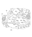
図18に示されるように、チェーンカバー40の第1バンク部40aにおける第1高壁部53bが、前記側方向で側縁部43iおよび側縁部43eとの間にそれぞれ低壁部53aを挟んで、両側縁部43i,43eの中間部に形成されてもよい。この場合、壁部50は、前記側方向で、互いに対向する1対の段差部51を有し、第1高壁部53bは、シリンダブロック1の下部1c(図1参照)からシリンダヘッド2に渡ってシリンダ軸線方向に延びている。このため、第1高壁部53bにより形成されるブリーザ通路54において、突出空間25aは、第1高壁部53bと1対の段差部51とにより形成される。
そして、第1高壁部53bおよび該ブリーザ通路54は、軸方向Aから見て、チェーン23の弛み側23aに沿って延びており、かつ該弛み側23aと重なる位置、およびシリンダボア26aと重なる位置に設けられる。そして、ブリーザ通路54に沿うチェーン23の走行方向が、ブローバイガスが前記動弁室に向かう方向に沿う方向であるので、走行するチェーン23により、ブリーザ通路54において該動弁室に向かうブローバイガスの流れが促進される。
As shown in FIG. 18, the first high wall portion 53b in the first bank portion 40a of the chain cover 40 sandwiches the low wall portion 53a between the side edge portion 43i and the side edge portion 43e in the lateral direction. Thus, it may be formed at an intermediate portion between the side edge portions 43i and 43e. In this case, the wall portion 50 has a pair of step portions 51 that face each other in the lateral direction, and the first high wall portion 53b extends from the lower portion 1c (see FIG. 1) of the cylinder block 1 to the cylinder head 2. It extends across the cylinder axis. Therefore, in the breather passage 54 formed by the first high wall portion 53b, the protruding space 25a is formed by the first high wall portion 53b and the pair of step portions 51.
The first high wall portion 53b and the breather passage 54 extend along the slack side 23a of the chain 23 when viewed from the axial direction A, and overlap with the slack side 23a and overlap with the cylinder bore 26a. Provided. Since the travel direction of the chain 23 along the breather passage 54 is a direction along the direction in which the blow-by gas faces the valve chamber, the chain 23 that travels causes the blow-by gas that travels toward the valve chamber in the breather passage 54. Flow is promoted.

前記各実施形態では、伝動機構は、動弁装置を駆動するためのものであったが、補機等を駆動するためのものであってもよい。また、伝動機構は、無端伝動帯としてのベルトを備える巻掛け伝動機構であってもよく、さらに、歯車機構であってもよい。
取付座91,92には、エンジンハンガ93以外の部品、例えば伝動機構を構成する部品、エンジンマウントブラケット、内燃機関の補機などが取り付けられてもよい。
カバー側油路Pa,Pbは、チェーンカバー40の外縁部43および壁部50のうちで、壁部50のみに設けられてもよい。
第1孔部71,171 ,81,181 および第2孔部72,172 ,82,182 の少なくとも一方は、両端部が開口する孔であってもよい。第1孔70,170 および第2孔80,180 は、1つの直線状の孔のみにより構成されてもよい。
カバー側油路は、前記実施形態では1つの交差部Pac,Pbcを形成する2つの孔である第1孔70,170 および第2孔80,180 により構成されたが、少なくとも2つの交差部を形成する3以上の孔(例えば、1つの交差部を形成する第1,第2孔と、別の1つの交差部を形成する第2,第3孔)により構成されてもよい。
機関本体側部材は、機関本体Eaに結合されて該機関本体Eaと一体化された中間部材を備え、該中間部材にチェーンカバー40などのカバー体が結合されてもよい。この場合、カバー体は、この中間部材を介して機関本体Eaに結合される。
1つの窓部に配置される2つの油圧制御弁のうちで、一方が位相制御機構の作動油を制御する弁であり、他方がリフト量制御機構の作動油を制御する弁であってもよい。
1つの窓部に配置される2つの油圧制御弁が、1または3以上の油圧式機構の作動油を制御するために使用されてもよい。
前記所定数の油圧制御弁において、少なくとも1つの油圧制御弁が動弁装置を制御し、残りの油圧制御弁が動弁装置以外の装置を制御してもよい。また、1つの窓部内に配置されるすべての油圧制御弁が動弁装置以外の装置を制御してもよい。
機関本体側部材に結合される周壁により形成される窓部は、油圧制御弁以外の部品、例えばテンショナリフタやクランク軸が配置または挿入される窓部であってもよい。
内燃機関は、V型以外の多気筒内燃機関であってもよく、また単気筒内燃機関であってもよい。また、動弁装置は、吸気カムおよび排気カムが設けられる共通の1つのカム軸を備えるSOHC型のものであってもよい。
チェーンカバー40のそれぞれのバンク部40a,40bに、カバー側油路Paまたはカバー側油路Pbと同様の油路が複数設けられてもよい。この場合、該各油路に対応して複数の窓部をそれぞれ形成する複数の周壁が設けられてもよい。
カバー側油路は、潤滑用のオイルが流れる油路であってもよい。
内燃機関は、例えば鉛直方向を指向するクランク軸を備える船外機等の船舶推進装置、または発電機など、車両以外の機械に使用されるものであってもよい。
In each of the above embodiments, the transmission mechanism is for driving the valve gear, but it may be for driving an auxiliary machine or the like. Further, the transmission mechanism may be a winding transmission mechanism including a belt as an endless transmission band, or may be a gear mechanism.
Parts other than the engine hanger 93, for example, parts constituting a transmission mechanism, an engine mount bracket, an auxiliary machine for an internal combustion engine, and the like may be attached to the mounting seats 91 and 92.
The cover side oil passages Pa and Pb may be provided only on the wall portion 50 among the outer edge portion 43 and the wall portion 50 of the chain cover 40.
At least one of the first hole portions 71, 171, 81, 181 and the second hole portions 72, 172, 82, 182 may be a hole having both ends opened. The first holes 70 and 170 and the second holes 80 and 180 may be configured by only one linear hole.
The cover side oil passage is constituted by the first holes 70 and 170 and the second holes 80 and 180 which are two holes forming one intersecting portion Pac and Pbc in the above embodiment, but at least two intersecting portions are formed. It may be configured by three or more holes to be formed (for example, first and second holes forming one intersecting portion and second and third holes forming another one intersecting portion).
The engine body side member may include an intermediate member that is coupled to the engine body Ea and integrated with the engine body Ea, and a cover body such as a chain cover 40 may be coupled to the intermediate member. In this case, the cover body is coupled to the engine body Ea via the intermediate member.
Of the two hydraulic control valves arranged in one window, one may be a valve that controls the hydraulic oil of the phase control mechanism, and the other may be a valve that controls the hydraulic oil of the lift amount control mechanism. .
Two hydraulic control valves arranged in one window may be used to control the hydraulic fluid of one or more hydraulic mechanisms.
In the predetermined number of hydraulic control valves, at least one hydraulic control valve may control the valve operating device, and the remaining hydraulic control valves may control devices other than the valve operating device. Further, all the hydraulic control valves arranged in one window portion may control devices other than the valve operating device.
The window portion formed by the peripheral wall coupled to the engine body side member may be a window portion in which a component other than the hydraulic control valve, for example, a tensioner lifter or a crankshaft is disposed or inserted.
The internal combustion engine may be a multi-cylinder internal combustion engine other than the V type, or may be a single cylinder internal combustion engine. Further, the valve gear may be of the SOHC type having a common cam shaft on which an intake cam and an exhaust cam are provided.
A plurality of oil passages similar to the cover-side oil passage Pa or the cover-side oil passage Pb may be provided in each of the bank portions 40a and 40b of the chain cover 40. In this case, a plurality of peripheral walls that respectively form a plurality of window portions corresponding to the respective oil passages may be provided.
The cover-side oil passage may be an oil passage through which lubricating oil flows.
The internal combustion engine may be used in a machine other than a vehicle, such as a ship propulsion device such as an outboard motor having a crankshaft oriented in the vertical direction, or a generator.

本発明が適用されたチェーンカバーを備える内燃機関を、クランク軸の軸方向から見たときの要部の図である。It is a figure of the principal part when an internal combustion engine provided with the chain cover to which the present invention is applied is viewed from the axial direction of the crankshaft. 図1のチェーンカバーの斜視図である。It is a perspective view of the chain cover of FIG. 図1のチェーンカバーを軸方向で外側から見た図である。It is the figure which looked at the chain cover of FIG. 1 from the outer side in the axial direction. 図1のチェーンカバーを軸方向で内側から見た図である。It is the figure which looked at the chain cover of FIG. 1 from the inner side in the axial direction. 図4の突条付近の斜視図である。FIG. 5 is a perspective view of the vicinity of the ridge in FIG. 4. 図3のVI−VI線断面図である。It is the VI-VI sectional view taken on the line of FIG. 図3のVII−VII線断面図である。It is the VII-VII sectional view taken on the line of FIG. 図3のVIII−VIII線断面図である。It is the VIII-VIII sectional view taken on the line of FIG. 図3のIX−IX線断面図である。It is the IX-IX sectional view taken on the line of FIG. 図4のX−X線断面図である。FIG. 5 is a sectional view taken along line XX in FIG. 4. 図4のXI−XI線断面図である。It is the XI-XI sectional view taken on the line of FIG. 図1のチェーンカバーにおいて、第1バンク側の窓部を中心とした要部拡大図である。In the chain cover of FIG. 1, it is the principal part enlarged view centering on the window part by the side of the 1st bank. 図1のチェーンカバーにおいて、第2バンク側の窓部を中心とした要部拡大図である。In the chain cover of FIG. 1, it is the principal part enlarged view centering on the window part by the side of the 2nd bank. 図1のチェーンカバーを外側から見たときの、第1バンク側の窓部を中心とした要部斜視図である。It is a principal part perspective view centering on the window part by the side of the 1st bank when the chain cover of FIG. 1 is seen from the outer side. 図1のチェーンカバーを内側から見たときの、第1バンク側の窓部を中心とした要部斜視図である。It is a principal part perspective view centering on the window part by the side of the 1st bank when the chain cover of FIG. 1 is seen from an inner side. 図1のチェーンカバーを外側から見たときの、第2バンク側の窓部を中心とした要部斜視図である。It is a principal part perspective view centering on the window part by the side of the 2nd bank when the chain cover of FIG. 1 is seen from the outer side. 図1のチェーンカバーを内側から見たときの、第2バンク側の窓部を中心とした要部斜視図である。It is a principal part perspective view centering on the window part by the side of the 2nd bank when the chain cover of FIG. 1 is seen from the inner side. 本発明の別の実施形態を示し、図3に相当する図の要部である。FIG. 4 shows another embodiment of the present invention and is a main part of a diagram corresponding to FIG. 3.

符号の説明Explanation of symbols

1…シリンダブロック、2,102 …シリンダヘッド、5…シリンダヘッドカバー、6…クランク軸、23,123 …チェーン、40…チェーンカバー、41…内面、42…外面、43…外縁部、50…壁部、51,51…段差部、53a…低壁部、53b…高壁部、54…ブリーザ通路、59…突条
Ea…機関本体、Pa,Pb…油路。
DESCRIPTION OF SYMBOLS 1 ... Cylinder block, 2,102 ... Cylinder head, 5 ... Cylinder head cover, 6 ... Crankshaft, 23, 123 ... Chain, 40 ... Chain cover, 41 ... Inner surface, 42 ... Outer surface, 43 ... Outer edge part, 50 ... Wall part , 51, 51 1, stepped portion, 53 a, low wall portion, 53 b, high wall portion, 54, breather passage, 59, protrusion Ea, engine body, Pa, Pb, oil passage.

Claims (7)

内燃機関の機関本体側部材の端部に結合されるカバー体であって、前記端部に結合される外縁部と、前記端部をクランクケースからシリンダヘッドに渡ってクランク軸の軸方向から覆うと共に前記端部と協働して内空間を形成する壁部とを有するカバー体において、 前記壁部は、前記軸方向で前記端部と対向する低壁部と、前記軸方向で前記端部と対向すると共に前記低壁部よりも前記軸方向で前記端部から離隔し、かつ前記軸方向での段差部を介して前記低壁部と段違いに形成される高壁部とを有し、
前記高壁部は、前記端部を前記クランクケースから前記シリンダヘッドに渡って覆うと共に、前記クランクケースにより形成されるクランク室内のブローバイガスを、前記シリンダヘッドにより形成されるヘッド側空間に導くブリーザ通路を形成することを特徴とするカバー体。
A cover body coupled to an end portion of an engine main body side member of an internal combustion engine, the outer edge portion coupled to the end portion, and the end portion covering from the crankcase to the cylinder head from the axial direction of the crankshaft And a wall having a wall portion that cooperates with the end portion to form an inner space, wherein the wall portion includes a low wall portion facing the end portion in the axial direction, and the end portion in the axial direction. And a high wall portion that is spaced apart from the end portion in the axial direction than the low wall portion and formed stepwise with the low wall portion through a step portion in the axial direction,
The high wall portion covers the end portion from the crankcase to the cylinder head, and guides a blow-by gas in a crank chamber formed by the crankcase to a head side space formed by the cylinder head. A cover body that forms a passage.
前記高壁部は、前記外縁部に隣接すると共に前記外縁部に沿って形成されることを特徴とする請求項1記載のカバー体。   The cover body according to claim 1, wherein the high wall portion is formed along the outer edge portion and adjacent to the outer edge portion. 前記内燃機関は、1対のバンクと、前記1対のバンクの内側に配置される吸気装置と、前記1対のバンクの外側に配置される排気装置とを備えるV型内燃機関であり、
前記高壁部は、前記壁部において前記1対のバンクの前記内側寄りに位置することを特徴とする請求項1または2記載のカバー体。
The internal combustion engine is a V-type internal combustion engine including a pair of banks, an intake device disposed inside the pair of banks, and an exhaust device disposed outside the pair of banks.
The cover body according to claim 1, wherein the high wall portion is positioned closer to the inside of the pair of banks in the wall portion.
前記低壁部は、前記低壁部に開口する窓部を形成すると共に前記端部に結合される周壁を有することを特徴とする請求項1から3のいずれか1項記載のカバー体。   The cover body according to any one of claims 1 to 3, wherein the low wall portion includes a peripheral wall that forms a window portion opening in the low wall portion and is coupled to the end portion. 前記高壁部は、前記軸方向で前記端部と対向する内面に形成された突条を有し、
前記突条は、前記軸方向から見て前記内燃機関のシリンダ軸線方向と交差する方向に延びていて前記ブリーザ通路を横切る堰を構成し、かつ前記段差部と前記外縁部とを連結していることを特徴とする請求項1から4のいずれか1項記載のカバー体。
The high wall portion has a protrusion formed on an inner surface facing the end portion in the axial direction,
The ridge extends in a direction intersecting the cylinder axial direction of the internal combustion engine as viewed from the axial direction, constitutes a weir crossing the breather passage, and connects the stepped portion and the outer edge portion. The cover body according to any one of claims 1 to 4, wherein:
前記軸方向で前記壁部を挟んで前記内空間と反対側の外空間には、無端伝動帯に張力を付与するテンショナを備える巻掛け伝動機構が配置され、
前記軸方向で前記低壁部を挟んで前記端部とは反対側に前記テンショナが配置され、
前記段差部は、前記テンショナの揺動範囲外に形成されることを特徴とする請求項1から5のいずれか1項記載のカバー体。
A winding transmission mechanism including a tensioner that applies tension to the endless transmission band is disposed in the outer space opposite to the inner space across the wall portion in the axial direction,
The tensioner is disposed on the opposite side of the end portion across the low wall portion in the axial direction,
6. The cover body according to claim 1, wherein the stepped portion is formed outside a swinging range of the tensioner.
油路を形成する通路壁が前記段差部に一体に設けられ、
前記通路壁は、前記低壁部および前記高壁部に渡って一体に設けられることを特徴とする請求項1から6のいずれか1項記載のカバー体。
A passage wall forming an oil passage is provided integrally with the step portion,
The cover body according to any one of claims 1 to 6, wherein the passage wall is integrally provided across the low wall portion and the high wall portion.
JP2008155981A 2008-01-25 2008-06-13 Cover body for internal combustion engine Pending JP2009197780A (en)

Priority Applications (1)

Application Number Priority Date Filing Date Title
JP2008155981A JP2009197780A (en) 2008-01-25 2008-06-13 Cover body for internal combustion engine

Applications Claiming Priority (2)

Application Number Priority Date Filing Date Title
JP2008015596 2008-01-25
JP2008155981A JP2009197780A (en) 2008-01-25 2008-06-13 Cover body for internal combustion engine

Publications (1)

Publication Number Publication Date
JP2009197780A true JP2009197780A (en) 2009-09-03

Family

ID=41141541

Family Applications (1)

Application Number Title Priority Date Filing Date
JP2008155981A Pending JP2009197780A (en) 2008-01-25 2008-06-13 Cover body for internal combustion engine

Country Status (1)

Country Link
JP (1) JP2009197780A (en)

Cited By (6)

* Cited by examiner, † Cited by third party
Publication number Priority date Publication date Assignee Title
CN103133172A (en) * 2011-11-25 2013-06-05 本田技研工业株式会社 Cover structure for internal combustion engine
JP2013113167A (en) * 2011-11-25 2013-06-10 Honda Motor Co Ltd Cover structure for internal combustion engine
JP2013113108A (en) * 2011-11-25 2013-06-10 Honda Motor Co Ltd Blow-by path structure for internal combustion engine
KR101327058B1 (en) 2012-02-21 2013-11-20 기아자동차주식회사 Apparatus for separating blow by gas and engine oil of vehicle engine and ventilation structure of blow by gas
JP2015094233A (en) * 2013-11-08 2015-05-18 本田技研工業株式会社 Head cover structure of engine and suspension structure of the same
JP2015094218A (en) * 2013-11-08 2015-05-18 本田技研工業株式会社 Cover mounting structure for internal combustion engine

Cited By (7)

* Cited by examiner, † Cited by third party
Publication number Priority date Publication date Assignee Title
CN103133172A (en) * 2011-11-25 2013-06-05 本田技研工业株式会社 Cover structure for internal combustion engine
JP2013113167A (en) * 2011-11-25 2013-06-10 Honda Motor Co Ltd Cover structure for internal combustion engine
JP2013113108A (en) * 2011-11-25 2013-06-10 Honda Motor Co Ltd Blow-by path structure for internal combustion engine
US8714124B2 (en) 2011-11-25 2014-05-06 Honda Motor Co., Ltd. Cover structure for internal combustion engine
KR101327058B1 (en) 2012-02-21 2013-11-20 기아자동차주식회사 Apparatus for separating blow by gas and engine oil of vehicle engine and ventilation structure of blow by gas
JP2015094233A (en) * 2013-11-08 2015-05-18 本田技研工業株式会社 Head cover structure of engine and suspension structure of the same
JP2015094218A (en) * 2013-11-08 2015-05-18 本田技研工業株式会社 Cover mounting structure for internal combustion engine

Similar Documents

Publication Publication Date Title
EP1788200A1 (en) Variable valve drive device, engine, and motorcycle
JP2009197780A (en) Cover body for internal combustion engine
JP2741492B2 (en) Engine oil passage structure
JP3881796B2 (en) Engine cooling system
JP4093512B2 (en) Secondary air supply device for engine exhaust
US7267094B2 (en) Lubrication system of small vehicle engine
JP3631863B2 (en) Internal combustion engine
JP3875417B2 (en) Fuel injection device for vehicle engine
JP2004132214A (en) Breather structure of overhead valve type internal combustion engine
JP2009174478A (en) Cover body provided with oil passage
JP2006299830A (en) Lubricating oil passage configuration of crankshaft
KR100890744B1 (en) Internal combustion engine
JP4657177B2 (en) Internal combustion engine
JP2009174477A (en) Cover body provided with oil passage
JP3963084B2 (en) 4-cycle engine for outboard motor
JP2002089217A (en) Oil pump structure of engine
JP4603206B2 (en) V-type engine
JPH02169808A (en) Cam shaft drive device for dohc engine
JP4057725B2 (en) Horizontally opposed 4-cycle engine for motorcycles
JP3599178B2 (en) V-type multi-cylinder engine
JPS61104149A (en) Cylinder block structure of engine
JPH11324627A (en) Oil passage structure of engine
JP2000220433A (en) Crankcase bleeding passage of v-type engine
JP4220949B2 (en) Lubricating oil passage for variable valve drive device, variable valve drive device, engine and motorcycle
JPH0732884Y2 (en) Lubricating oil passage for V-type engine