EP1787397B1 - Procedes et dispositif de codage ldpc - Google Patents
Procedes et dispositif de codage ldpc Download PDFInfo
- Publication number
- EP1787397B1 EP1787397B1 EP05775250.3A EP05775250A EP1787397B1 EP 1787397 B1 EP1787397 B1 EP 1787397B1 EP 05775250 A EP05775250 A EP 05775250A EP 1787397 B1 EP1787397 B1 EP 1787397B1
- Authority
- EP
- European Patent Office
- Prior art keywords
- module
- encoder
- code
- control signal
- memory
- Prior art date
- Legal status (The legal status is an assumption and is not a legal conclusion. Google has not performed a legal analysis and makes no representation as to the accuracy of the status listed.)
- Expired - Lifetime
Links
Images

Classifications
-
- H—ELECTRICITY
- H03—ELECTRONIC CIRCUITRY
- H03M—CODING; DECODING; CODE CONVERSION IN GENERAL
- H03M13/00—Coding, decoding or code conversion, for error detection or error correction; Coding theory basic assumptions; Coding bounds; Error probability evaluation methods; Channel models; Simulation or testing of codes
- H03M13/03—Error detection or forward error correction by redundancy in data representation, i.e. code words containing more digits than the source words
- H03M13/05—Error detection or forward error correction by redundancy in data representation, i.e. code words containing more digits than the source words using block codes, i.e. a predetermined number of check bits joined to a predetermined number of information bits
- H03M13/11—Error detection or forward error correction by redundancy in data representation, i.e. code words containing more digits than the source words using block codes, i.e. a predetermined number of check bits joined to a predetermined number of information bits using multiple parity bits
-
- H—ELECTRICITY
- H03—ELECTRONIC CIRCUITRY
- H03M—CODING; DECODING; CODE CONVERSION IN GENERAL
- H03M13/00—Coding, decoding or code conversion, for error detection or error correction; Coding theory basic assumptions; Coding bounds; Error probability evaluation methods; Channel models; Simulation or testing of codes
- H03M13/65—Purpose and implementation aspects
- H03M13/6508—Flexibility, adaptability, parametrability and configurability of the implementation
-
- H—ELECTRICITY
- H03—ELECTRONIC CIRCUITRY
- H03M—CODING; DECODING; CODE CONVERSION IN GENERAL
- H03M13/00—Coding, decoding or code conversion, for error detection or error correction; Coding theory basic assumptions; Coding bounds; Error probability evaluation methods; Channel models; Simulation or testing of codes
- H03M13/03—Error detection or forward error correction by redundancy in data representation, i.e. code words containing more digits than the source words
- H03M13/05—Error detection or forward error correction by redundancy in data representation, i.e. code words containing more digits than the source words using block codes, i.e. a predetermined number of check bits joined to a predetermined number of information bits
- H03M13/11—Error detection or forward error correction by redundancy in data representation, i.e. code words containing more digits than the source words using block codes, i.e. a predetermined number of check bits joined to a predetermined number of information bits using multiple parity bits
- H03M13/1102—Codes on graphs and decoding on graphs, e.g. low-density parity check [LDPC] codes
- H03M13/1148—Structural properties of the code parity-check or generator matrix
- H03M13/118—Parity check matrix structured for simplifying encoding, e.g. by having a triangular or an approximate triangular structure
-
- H—ELECTRICITY
- H03—ELECTRONIC CIRCUITRY
- H03M—CODING; DECODING; CODE CONVERSION IN GENERAL
- H03M13/00—Coding, decoding or code conversion, for error detection or error correction; Coding theory basic assumptions; Coding bounds; Error probability evaluation methods; Channel models; Simulation or testing of codes
- H03M13/61—Aspects and characteristics of methods and arrangements for error correction or error detection, not provided for otherwise
- H03M13/611—Specific encoding aspects, e.g. encoding by means of decoding
-
- H—ELECTRICITY
- H03—ELECTRONIC CIRCUITRY
- H03M—CODING; DECODING; CODE CONVERSION IN GENERAL
- H03M13/00—Coding, decoding or code conversion, for error detection or error correction; Coding theory basic assumptions; Coding bounds; Error probability evaluation methods; Channel models; Simulation or testing of codes
- H03M13/03—Error detection or forward error correction by redundancy in data representation, i.e. code words containing more digits than the source words
- H03M13/05—Error detection or forward error correction by redundancy in data representation, i.e. code words containing more digits than the source words using block codes, i.e. a predetermined number of check bits joined to a predetermined number of information bits
- H03M13/11—Error detection or forward error correction by redundancy in data representation, i.e. code words containing more digits than the source words using block codes, i.e. a predetermined number of check bits joined to a predetermined number of information bits using multiple parity bits
- H03M13/1102—Codes on graphs and decoding on graphs, e.g. low-density parity check [LDPC] codes
- H03M13/1148—Structural properties of the code parity-check or generator matrix
- H03M13/116—Quasi-cyclic LDPC [QC-LDPC] codes, i.e. the parity-check matrix being composed of permutation or circulant sub-matrices
Definitions
- the present invention is directed to methods and apparatus for encoding data for the purposes of facilitating the detection and/or correction of errors, e.g., through the use of parity check codes such as low-density parity-check (LDPC) codes.
- parity check codes such as low-density parity-check (LDPC) codes.
- Error correcting codes are ubiquitous in communications and data storage systems. Error correcting codes compensate for the intrinsic unreliability of information transfer in these systems by introducing redundancy into the data stream. Recently considerable interest has grown in a class of codes known as low-density parity-check (LDPC) codes. LDPC codes are provably good codes. On various channels, LDPC codes have been demonstrated to be really close to the channel capacity - the upper limit for transmission established by Claude Shannon.
- LDPC low-density parity-check
- LDPC codes are often represented by bipartite graphs, called Tanner graphs, in which one set of nodes, the variable nodes, correspond to bits of the codeword and the other set of nodes, the constraint nodes, sometimes called check nodes, correspond to the set of parity-check constraints which define the code. Edges in the graph connect variable nodes to constraint nodes. A variable node and a constraint node are said to be neighbors if they are connected by an edge in the graph.
- a bit sequence associated one-to-one with the variable nodes is a codeword of the code if and only if, for each constraint node, the bits neighboring the constraint (via their association with variable nodes) sum to zero modulo two, i.e., they comprise an even number of ones.
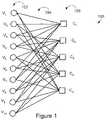
- An exemplary bipartite graph 100 determining an exemplary (3,6) regular LDPC code of length ten and rate one-half is shown in Fig. 1 .
- Length ten indicates that there are ten variable nodes V 1 -V 10 , each identified with one bit of the codeword X 1 -X 10 .
- the set of variable nodes V 1 -V 10 is identified in Fig. 1 by reference numeral 102.
- Rate one half indicates that there are half as many check nodes as variable nodes, i.e., there are five check nodes C 1 -C 5 identified by reference numeral 106. Rate one half further indicates that the five constraints are linearly independent.
- Exemplary bipartite graph 100 includes edges 104, wherein the exemplary (3,6) regular LDPC code has 3 edges connected to each variable node and 6 edges connected to each constraint node and at most one edge between any two nodes.
- FIG. 1 illustrates the graph associated with a code of length 10
- representing the graph for a codeword of length 1000 would be 100 times more complicated.
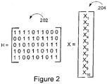
- the matrix H 202 includes the relevant edge connection, variable node and constraint node information.
- each column corresponds to one of the variable nodes while each row corresponds to one of the constraint nodes. Since there are 10 variable nodes and 5 constraint nodes in the exemplary code, the matrix H 202 includes 10 columns and 5 rows.
- the entry of the matrix 202 corresponding to a particular variable node and a particular constraint node is set to 1 if an edge is present in the graph, i.e., if the two nodes are neighbors, otherwise it is set to 0.
- variable node V 1 is connected to constraint node C 1 by an edge, a one is located in the uppermost left-hand corner of the matrix 202.
- variable node V 5 is not connected to constraint node C 1 so a 0 is positioned in the fifth position of the first row of matrix 202 indicating that the corresponding variable and constraint nodes are not connected.
- the constraints are linearly independent if the rows of H 202 are linearly independent vectors over GF[2], where GF[2] is the binary Galois Field.
- the codeword X which is to be transmitted can be represented as a vector 204 which includes the bits X 1 -X n of the codeword to be processed.
- Encoding LDPC codes refers to the procedure that produces a codeword from a set of information bits. By preprocessing the LDPC graph representation or the matrix representation, the set of variable nodes corresponding information bits can be determined prior to actual encoding.
- the present invention is directed to encoding methods and apparatus, e.g., methods and apparatus for implementing a low density parity check (LDPC) encoder.
- Various embodiments of the invention are directed to particularly flexible encoders which allow a single encoder to be used to encode codewords of different lengths. This allows an LDPC encoder of the present invention to switch between encoding codewords of a first length for a first application, e.g., a first communications application or data storage application, to encoding codewords of a second length for a second application.
- a wide variety of codeword lengths can be supported using the same hardware allowing for changes in codeword length through simple modifications in the codeword description used in the encoder. Codeword descriptions may be reflected in relatively simple microcode which can be executed as needed for a particular application.
- the encoder of the present invention can store multiple sets of microcode corresponding to different codes structures.
- a code structure is selected to be used for encoding, the corresponding microcode is selected and codewords of a particular length corresponding to the selected code structure are generated.
- codewords of different lengths may be generated by selecting different code lifting factors. Use of a code lifting factor less than the maximum supported code lifting factor will normally result in some memory locations, e.g., block storage locations, going unused in the encoder memory. The number of block storage locations provided in memory is normally determined by the maximum supported codeword size.
- the encoder of the present invention can switch between different lifting factors thereby allowing the encoder to switch between generating codewords of different lengths.
- the encoder of the present invention can be used to generate codewords of a length which is well suited for a particular application and is not constrained by hardware to generating codewords of a single length.
- the maximum supported codeword length in many cases will be a function of the amount of memory available for storing blocks of bits during encoding.
- the maximum supported codeword size may be K x N x L bits with the different size codewords including integer multiples of (N x L) bits up to the maximum of K multiples, where K, N and L are positive integers.
- the encoder of the present invention is particularly well suited for encoding codewords which can be generated according to LDPC graphs which define a code that possess a certain hierarchical structure in which a full LDPC graph appears to be, in large part, made up of multiple copies, Z, e.g., of a Z times smaller graph.
- the Z graph copies may, but need not be, be identical.
- the smaller graph we will refer to the smaller graph as the projected graph, the full graph as the lifted graph, and Z as the lifting factor.
- the projected graph serves as the basis of generating or describing the larger lifted graph which described the code structure used to control encoding.
- the encoder of the present invention is not so limited.
- ⁇ will be used herein to refer to a set of permuation matrices which is usually a group of permuation matrixes.
- ⁇ can in general be chosen using various criteria.
- One of the main motivations for the above structure is to simplify hardware implementation of decoders and encoders. Therefore, it can be beneficial to restrict ⁇ to permutations that can be efficiently implemented in hardware, e.g., in a switching network.
- an LDPC encoding procedure can, and in various embodiments is, laid as an ordered sequence of matrix addition and multiplication operations may be translated into a sequence of commands.
- this sequence of encoding commands for an exemplary graph G as the encoding microcode of G.
- the actual encoding is then accomplished by sequentially executing the microcode of G, using an encoder of the present invention, which performs various operations in accordance with the microcode on a physical memory preloaded with information bits, e.g., bits to be encoded.
- Each command comprises an operator op and a memory location indicator.
- the encoder control logic either reads out a bit location in the memory determined by the memory location indicator and accumulates it to a register, or, writes the register value to location ⁇ and resets the register value to zero.
- the size of the microcode i.e., the number of commands of within, is at least equal to the number of edges in graph G; often, they might be roughly the same.
- the complexity of the representation comprises, roughly, the number of bits required to specify the permutation matrices,
- Z.
- Z 16 for n ⁇ 1000 where n is the codeword block length.
- x can be treated as a vector of elements in GF(2 ⁇ Z), instead of a vector of binary element, where GF(2 ⁇ Z) is Galois field of 2 ⁇ Z elements.
- the encoding process as matrix-vector multiplication and vector addition laid out in the background section may be mimicked: every nonzero element 1 in a matrix in the projected graph is replaced by its corresponding Z ⁇ Z permutation matrix; every bit in a vector is replaced by a Z-bit vector.
- the encoding procedure of a LDPC graph using G as the projected graph can be largely specified as a lifting of the above encoding process for the projected graph. That is accomplished through replacing bit operations in the original algorithm to bit vector operations in the lifted algorithm.
- the Z bit vectors are subject to a permutation operation, e.g., a re-ordering operation.
- the re-ordering operation may be a rotation operation, or rotation for short. These rotation operations generally correspond to the rotations associated to the vector edges that interconnect the Z copies of the projected graph to form the single large graph. Therefore, in the lifted microcode, each command comprises an operator op, a rotation number r , and a memory location indicator.
- Lifting the microcode of the projected graph in large part specifies the encoding for the lifted graph.
- An exception is if a matrix inversion, for calculating the matrix ⁇ -1 , exists in the projected graph. In such a case, the inversion is not lifted directly to a matrix inversion in the lifted graph. Instead, the matrix inversion is done in the ring over Z ⁇ Z permutation matrices and the corresponding encoding commands results in a new set of commands specifying the matrix inversion. In those commands, the required rotations are apparent after appropriate preprocessing of the LDPC representation.
- the size of the microcode used in accordance with the invention to describe the lifted graph is thus roughly equal to the number of edges in the projected graph plus the number of additional commands specifying the inversion, which is often small. Therefore, for identical block length, increasing the lifting factor generally reduces the size of the encoding microcode. For large block length, this may save significantly in microcode description memory, e.g., a relatively small memory may be used to store the information describing the large graph to be used for encoding.
- the throughput of the encoder is usually required to match that of the decoder.
- implementing hardware parallelism Z on both the encoder and decoder often results in a higher throughput for the encoder than is necessary to match the decoder throughput since the decoder needs a few more iterations to converge, e.g., complete decoding of a codeword.
- using an implementation parallelism Z invokes a high number of parallel units in generating an excessive throughput.
- Various features of the present invention are directed to methods and apparatus for implementing a vector LDPC encoder with implementation parallelism N using microcode that describes a lifted graph with lifting factor Z, where N is a divisor of Z.
- Implementation parallelism N may be chosen to match the required throughput, thus using the minimum hardware complexity.
- the vector LDPC encoder with implementation parallelism N is capable of generating, e.g., encoding data to produce codewords corresponding to a class of LDPC codes, with the same rate but different block sizes, from the same microcode describing a lifted graph with lifting factor Z.
- Z can be factored K 1 x K 2 x N
- the projected graph has n variable nodes
- the novel encoder may generate three different codes of different codeword sizes N x n, K 2 x N x n and K 1 x K 2 x N x n.
- a device using the encoder of the present invention can, and often does, switch between encoding using different graphs described in stored microcode depending on the application so that the codewords generated can be of a block size which is appropriate for the particular application. For example, codewords of a first size may be generated for wireless communications while codewords of a second size may be generated for fiber optic communication purposes.
- the present invention is directed to methods and apparatus for implementing LDPC encoders.
- Various embodiments of the invention are directed to LDPC encoders and encoding methods which can be implemented in a hardware efficient manner while being relatively flexible with regard to the code structure that can be used during encoding and the size of generated codewords.
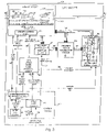
- Fig. 3 illustrates an exemplary LDPC encoder 300 implemented in accordance with the present invention.
- the encoder includes a memory module 302, a control module 312, a code lifting based block selection module 310, an N element controllable permuter 304, an N element vector accumulator module 306 and a controllable storage device 308 which are coupled together as shown in Fig. 3 .
- the terms permuter and permutator are used interchangeable in the present application to refer to the same thing.
- the various elements of the LDPC encoder 300 and their function will be described in detail below.
- the encoder 300 of the present invention can support different codes with the use of different code descriptions and/or with the use of different codeword lengths, as indicated by different lifting factors, for the same code description.
- the memory module 302 includes a set of K x N x L memory locations (318, 320, 322) where K x N x L is the maximum supported codeword size.
- An input 301 allows data to be encoded to be written into said memory.
- An output 303 allows a codeword stored in the memory 314 to be read out once encoding has been completed.
- the memory module 302 also includes a set of K x N x 1 memory locations (319, 321, 323) used to store temporary values. Other embodiments may not require and may not use temporary storage values.
- Codewords of smaller sizes can also be supported using the memory 314.
- the memory locations in memory 314 are arranged, into K NxL blocks used to store codeword values, Blk 1 318, Blk 2 230, Blk K 322 and K Nx1 blocks used to store temporary values Blk 1 319, Blk 2 321, Blk K 323.
- Each of the K x N x L memory locations is normally 1 bit.
- N bits are normally read from or written to memory module 314 at a time.
- An N bit wide bus 340 couples an N bit wide read output of memory module 302 to an N bit wide input of the N element controllable permuter 304 which can reorder the bits prior to them being supplied to the N element vector accumulator 306 over an N bit wide bus 342.
- the N element controllable permuter 304 receives a reordering control signal r2 373 which is generated as a function of stored code description information, e.g., control code such as microcode.
- the signal r2 373 controls what, if any, reordering of bits is to be performed on the N bits obtained from memory prior to the bits being supplied to the N element vector accumulator module 306.
- the N element vector accumulator module 306 includes N accumulator circuits arranged in parallel. Each of the N accumulator circuits generates a one bit binary sum corresponding to one of the N input bits from the N element controllable permuter 304 and a corresponding one of N bits read out of the controllable storage device 308. This is an efficient way of implementing an XOR operation. Thus each accumulator circuit performs an XOR operation. In this manner, the N element vector accumulator 306 generates N accumulated values in parallel. The N values generated by the accumulator module 306 are supplied in parallel over the N bit wide bus 344 to the controllable storage device 308.
- the controllable storage device 308 includes an input MUX 328, an output MUX 308, and a set of K N-bit registers 326.
- the input MUX 328 is controlled by a block select control signal 360 to determine which one of K N bit registers 332, 334, 336 an N bit block is written to when the read/write signal 350 indicates the output of the vector accumulator module is to be stored in the controllable storage device 308.
- Output MUX 330 is coupled to the N bit wide bus 346 and outputs the N bit block indicated by the block select control signal 360 when the read/write control signal 350 indicates a read operation is to be performed.
- Each set of N bits read out from controllable storage device 308 are supplied to both the memory module 302 and to the second input of the N element vector accumulator module 306.
- the N bits are written to memory at the end of a sequence of accumulator operations, e.g., as determined by the stored code description.
- the control module 312 is responsible for generating a variety of control signals as a function of the particular code description, e.g., control code such as microcode, stored in encoder description information module 372, selected to be used at a particular point in time.
- the code description information can be loaded into the stored encoder description information module 372, e.g., from a devices main memory via input 371.
- input 371 may be omitted.
- the generation of the signals produced by the encoder description information module 372 are driven by a control signal 375 generated by an outer loop counter 374.
- the outer loop counter 374 is driven by an inner loop control signal 377 generated by an inner loop counter 370.
- the inner loop counter 370 generates a second selection module control signal 356 and the inner loop control signal 377 as a function of a code lifting factor control signal SK 348 which is supplied to the inner loop counter 370 as a control value.
- the code lifting factor control signal can be used to specify the length of the codeword to be generated and may assume values from 1 to K where K indicates the total number of NxL bit blocks in memory 314. Thus, by using different code lifting factors, codewords of different sizes may be generated where each of the different supported codeword sizes will be an integer multiple of NxL. In cases where SK ⁇ K, one or more blocks in memory 314 and one or more registers in the set of registers 326 will normally go unused.
- the stored encoder description information module 372 includes control code, e.g., microcode. This code, when executed in response to the outer loop control signal 375, generates a read/write signal 350 specified by an op value included in the executed line of microcode. The signal 350 is supplied to both the memory module 302 and the controllable storage device 308.
- the stored encoder description information module 372 also generates a memory address control signal 352 which is supplied to the memory module 302 when a read/write operation is to be performed, a first selection module control signal r1 354 which is supplied to the code lifting based block selection module 310 and the reordering control signal r2 373 which is supplied to the controllable permuter 304 to control the reordering of values read from memory module 302.
- Code lifting based block selection module 310 receives the first selection module control signal r1 354 from the stored encoder description information module 372 and a second selection module control signal 356 generated by inner loop counter 370.
- the code lifting based block selection module 310 generates a block address select signal 358 which is supplied to memory address logic 316 to indicate a particular block of memory 314 to be accessed at a particular point in time.
- the code lifting based block selection module 310 also generated the block select control signal 360 which is used to control which block of information, e.g., which register 332, 334, 336 bits are to be accessed in the controllable storage device 308 at a particular point in time.
- the various components of encoder 300 are driven by a common clock signal so that the various operations and the incrementing of the counters 370, 374 operate in a synchronized manner.
- the set of information bits initially stored in memory module 314 will be transformed as a result of the encoder processing operations and memory access operations performed under direction of the stored encoder description information module 372 into a codeword.
- This codeword may be read out and, e.g., transmitted or stored.
- a single codeword generated by performing an encoding operation may include a total number of bits T, where T may be several hundred or even thousands of bits.
- bits to be encoded may be arranged into K x L X N bit vectors, where N is a positive integer and K is a positive integer greater than 1.
- Each N bit vector may be read from memory. The vector read from memory can then be processed using N processing units in parallel.
- the level of parallelism N is lower than the lifting factor Z.
- codewords of different sizes can be generated using the same set of code description information.
- codewords less than the maximum codeword size for a given implementation L x K x N
- the different size codewords will be multiples of NxL bits.
- the dimension of ⁇ is equal to the product of the dimensions of ⁇ i , where ⁇ i is the group of K i ⁇ K i permutation matrices.
- ⁇ i is the group of K i ⁇ K i permutation matrices.
- a large lifting may be implemented as multiple smaller sequential liftings.
- Z K 1 x K 2 x K 3
- K 1 , K 2 , K 3 are dimensions of ⁇ 1 , ⁇ 2 , ⁇ 3 respectively.
- the lifting group ⁇ to be a product-lifting group.
- a product lifting can equivalently be viewed as a multi-dimensional lifting.
- the present encoder 300 of the present invention uses liftings which can be implemented as multi-dimensional liftings.
- the projected code is of size P, i.e., with P variable nodes.
- Various features of the invention are directed to a method and apparatus for encoding a graph with an implementation parallelism N in a flexible but relatively hardware efficient manner.
- K can be used as a lifting control factor and, when N is fixed, can be indicative of the size of the codeword to be generated.
- lifting factor Z is a sequence of commands each of which carries an operator op, a rotation number r, and a memory location a.
- An encoder 300 implemented using parallelism Z executes each command in the following way: if op indicates a read, the controller reads a Z-bit vector from the memory at location a, reorders it the amount r, and accumulates the reordered value into a Z-bit register; if op indicates a write, the controller writes the value of the Z-bit register into the memory at location a. And the encoding is accomplished by executing the whole sequence of commands.
- the microcode which is executed may be stored in the encoder description information module 372 which, in addition to storing the microcode to be used is responsible for accessing and executing the instructions included in the microcode.
- each d j is an N-bit vector, where j is an integer value used as indexes.
- r (r 1 ,r 2 )
- r 1 is the reordering amount, e.g., amount of cyclic rotation, in group ⁇ 1
- r 2 is the reordering amount, e.g., amount of cyclic rotation, in group ⁇ 2 .
- ⁇ 1 ( d, r ) we use the notation ⁇ 1 ( d, r ) to represent a reordering by amount r on vector d (of K element) in group ⁇ 1 and the notation ⁇ 2 ( d , r ) to represent a reordering by amount r on vector d (of N elements) in group ⁇ 2 .
- the reordering can be also thought of as a location permutation, so that the element d j at original location j goes to a new location denoted as ⁇ 1,r (j) in the reordered data. Then the reordering can be thought as a 2-stage reordering procedure.
- the reordered data d" is accumulated to a Z-bit register.
- the Z bit register is implemented as a set of K N-bit registers 332, 334, 336.
- a command that writes Z-bit register to location ⁇ and resets the Z-bit register can also be decomposed into K steps in accordance with the present invention, indeed in a much simpler way.
- step j we write the jth register of the K N-bit registers 332, 334, 336 to a location determined by j and location a, and reset that register 332, 334 or 336.
- Running through j 1, ..., K, we obtain the same result as executing the command with Z-bit vector operations.
- a control module 312 controls the number of steps executing a command through an inner loop counter 370.
- Counter 370 increments by 1 at each step and resets upon reaching a maximum count determined by the code lifting factor control signal 348.
- the outer loop counter 374 determines the current executed encoding command by accessing stored encoder description information module 372.
- Stored encoder description information module 372 outputs the command, in the form of various signals generated according to the command, to be applied at the location determined by the outer loop counter 374.
- a command carries an operator op, a reordering number r, and a memory location a.
- Operation op specifies the read/write signal 350 to a memory module 302, the memory location a determines the memory address control signal 352 coupled to the memory module 302, and reordering number r is separated into two parts (r 1 , r 2 ) that each specifies the reordering element in the group ⁇ 1 and ⁇ 2 respectively.
- Signal r 1 354 is supplied to code lifting based block selection module 310 for used in generating a block address select signal 358 used to control which block of memory in memory module 302 is accessed while signal r 2 373 is supplied to the permuter 304 to control the permuting of the N elements of a block read from memory 302.
- code lifting based block selection module 310 has a first selection module control signal 354 coupled to part r 1 of the reordering number r in the command from the said control module 312. Driven by the second selection control signal 356 generated by inner loop counter 370 of the control module 312, and controlled by the control signal r 1 354, the code lifting based block selection module 310 outputs block address selection signal 358 which assumes values from 1 to K, and block selection control signal 360 which assumes values ⁇ 1r 1 , (1), ⁇ 1,r 1 (2), ..., ⁇ 1r 1 (K).
- the memory module 302 has an input for receiving the read/write signal 350 coupled to the operator op output of the stored encoder description information and another input for receiving the memory address control signal 352 which corresponds to the memory location a carried by the microcode instruction stored in module 372 that is being executed at a particular point in time.
- the memory module 302 includes memory 314 arranged into K x (N x L) 1-bit storage locations 318, 320, 322 and K x (N x 1) 1-bit storage locations 319, 321, 323. For convenience, we identify the storage locations with K blocks of (N x L) 1-bit locations as block 1, ..., K used for codeword storage, and we identify the storage locations with K blocks of (N x 1) 1-bit locations as block 1, ..., K used for temporary storage of values.
- the memory 314 is accessed at a location that is a function of the memory address control signal a 352 and block address select signal k 358.
- Memory address logic module 316 implements such a function. Given ( a, k ) , the memory module 302 either reads or writes the N-bit vector on location a in the k th block depending on whether the read/write signal 350 indicates that a read or a write operation should be performed.
- a read-out of memory module 302 outputs an N-bit vector 340 read from memory 314. This N bit vector is fed into the N element controllable permuter module 304.
- Module 304 implements the reordering in group ⁇ 2 its reordering control signal is coupled to the r 2 signal output of the stored encoder description information module 372.
- the reordering number r from which the r 2 signal is derived, used at a particular point in time is obtained from the microcode command from the information module 372 which is being executed at the particular point in time.
- a reordered N-bit vector output of the permuter module 304 is coupled to the first N-bit vector input 342 of an N element vector accumulator module 306.
- the second N-bit vector input 346 of the accumulator module 306 is fed from the controllable storage device module 308 which includes K N bit registers 332, 334, 336.
- the vector accumulator module 306 generates an N-bit vector output as the XOR sum of the two N-bit vector inputs.
- the vector accumulator module 306 is implemented using N XOR circuits arranged in parallel with each XOR circuit being coupled to a different summer for summing the result of the XOR operation to the most recently generated XOR result produced by the particular one of the N XOR circuits.
- the N bit wide output of the Accumulator module is coupled to the input 344 of the controllable storage device module 308.
- the controllable storage device module 308 includes K registers, each register storing N-bits.
- a block select control signal 360 coupled to the code lifting based block selection module 310, determines which one of the K registers is to be accessed at a particular point in time.
- a read/write control signal 350 coupled to the operator op carried in the command from the control module 312, determines the accessing mode, e.g., a read or a write accessing mode. Assume the block selection control signal 360 says j. If the control signal is a read, then the N-bit output vector from the controllable storage device 308 takes the value of the jth register, and the accumulated value from the N element vector accumulator module 306 is written into the jth register.
- the reordered value from the N element controllable permuter 304 is accumulated into the jth register indicated by the block select control signal 360. If the read/write control signal 350 is a write, the output vector again assumes the value of the jth register, and we then reset the jth register to zero.
- each N bit vector operation involves the execution of a command in a microcode that is descriptive of the code structure to be used for encoding.
- each N bit command is implemented in K steps in a sequence controlled by part of the stored microcode command information and one or more counters.
- the selected code lifting factor which can serve as a codeword length selection signal since it will control the length of generated codewords, can be specified through the code lifting factor control signal 348.
- the signal 348 is supplied to the inner loop counter 370 and determines the maximum count of the inner loop counter 370.
- control code may serve as code description information which is stored in stored in the stored encoder description information module 372 and executed, e.g., a line at a time, to implement an encoding operation.
- the maximum supported codeword length will be KxNxL which is 640 in this example.
- the projected graph described by the code has 4 check nodes and 10 variable nodes. When lifted by the maximum lifting factor Z this will result in a code structure having 256 (64x4) check nodes and 640 (64x10) variable nodes.
- op column 1 In the microcode, shown in Table 1, in the op column 1 is used to indicate a read while a 0 is used to indicate a write instruction.
- the control values r1 and r2 are stored in the value r.
- memory accessed is used for codeword storage, e.g. one of the K blocks 318, 320, 322 is accessed.
- memory accessed is used for temporary storage of values, e.g., one of the K blocks 319, 321, 323 is accessed.
- the methods and apparatus of the present invention can be used to implemented a wide variety of devices including, for example, wireless terminals, base stations, data storage devices and other types of devices where encoding and/or decoding of data to prevent and/or correct errors might be useful.
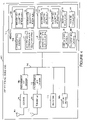
- FIG 4 is a drawing of an exemplary wireless terminal (WT) 1000, e.g., mobile node, implemented in accordance with LDPC encoder/decoder apparatus that use methods of the present invention.
- WT 1000 includes a receiver 1002, a receiver antenna 1004, a programmable LDPC decoder 1006, a transmitter 1008, a transmitter antenna 1010, a programmable LDPC encoder 1012, a processor 1014, user I/O devices 1015 and a memory 1016.
- the programmable LDPC decoder 1006, programmable LDPC encoder 1012 (which can be implemented using the encoder 300 of Fig. 3 ), processor 1014, user I/O devices 1015 and memory 1016 are coupled together via a bus 1018 over which the various elements may interchange data and information.
- the receiver 1002 is coupled to the receiver antenna 1004 through which the WT 1000 may receive signals from other devices, e.g., encoded downlink signals from a base station.
- the receiver 1002 is also coupled to the programmable LDPC decoder 1006 which may decode received downlink signals in accordance with the invention.
- Received signals may include, e.g., in addition to LDPC coded data, signals, e.g., control information, used to indicate LDPC code structure used to encode data which is being received and/or the codeword length of codewords included in received data.
- the received data may include codewords corresponding to different applications.
- the decoder may switch from decoding data corresponding to a first code structure and codeword length to decoding data corresponding to a second code structure and a second codeword length.
- the first and second codeword structures may be different with the decoder being loaded with the appropriate code structure information, e.g., control code in the form of microcode, in response to information included in the received information.
- the control information is normally not encoded using LDPC codes to facilitate rapid detection and interpretation of the control information.
- the first and second codeword lengths can also be different. In some cases, the first and second code structures are the same but the codeword lengths of data corresponding to different applications may be different.
- code structure information need not be updated to decode the codewords of different sizes and merely the codeword length information, e.g., lifting factor information need be supplied to the decoder as the codeword length of the received data changes.
- the codeword length information maybe specified as a code lifting factor for the code structure being used.
- code structure information e.g., control code
- codeword length information can be used to set the codeword length for decoding purposes. Such information can be conveyed to the decoder 1006 from memory 1016 via bus 1018.
- the transmitter 1008 is coupled to the transmitter antenna 1010 through which the WT 1000 may transmit uplink signals including encoded uplink signals to base stations.
- the transmitter 1008 is coupled to the programmable LDPC encoder 1012 which encodes various uplink signals, e.g., data signals corresponding to different applications, prior to transmission.
- the encoder can be loaded with different sets of code description information, e.g., different sets of control codes such as microcode, corresponding to different code structures.
- the encoder 1012 can be supplied with codeword length information, e.g., in the form of code lifting factor information, used to control the length of codewords generated by the encoder 1012.
- Information selecting the codeword structure and/or codeword length may be obtained from received information, e.g., the encoder may encode data generated by an application using the same codeword structure and codeword length as was used to decode received data intended for the particular application generating data.
- the encoder may be programmed to match the encoding structure and codeword length being used by another device with which the wireless terminal is interacting.
- a user of the device may specify use of a particular codeword structure and/or codeword length or such information may be specified by a communications routine or other program stored in the wireless terminal.
- Code structure information and/or codeword length information can be conveyed from memory 1016 to the programmable LDPC encoder 1012 over bus 1018.
- User I/O devices 1015 e.g., keypads, speakers, microphones, displays, etc. provide interfaces for the user to input data and information, e.g., data and information to be encoded and communicated to another WT and for the user to output and/or display received data/information, e.g., received data and information from a peer node which has been decoded.
- User I/O devices 1015 provide an interface allowing a user to select and/or specify the code associated with a set of data, code length indicator, and/or sets of code description information to be used by the programmable LDPC decoder 1006 and/or programmable LDPC encoder 1012.
- the processor 1014 e.g., a CPU, executes the routines and uses the data/information in memory 1016 to control the operation of the wireless terminal 1000 and implement the methods of the present invention.
- Memory 1016 includes a group 1025 of encoder code description information sets 1026, 1028 and a group 1029 of decoder code description information sets 1030, 1032.
- Each encoder code description information set 1026, 1028 includes control codes, e.g., microcode, which reflects the code structure of the code to be used for encoding data.
- Each set of information 1026, 1028 corresponds to a different code structure.
- the encoder code description information can be loaded into the encoder control module of the programmable LDPC encoder 1012 and used, e.g., as stored encoder description information, to control encoding of data.
- each of the decoder code description information sets 1030, 1032 includes control codes, e.g., microcode, which reflects the code structure of the code to be used for decoding data.
- Each set of decoder code description information 1030, 1032 corresponds to a different code structure.
- the decoder code description information can be loaded into the control module of the programmable LDPC decoder 1006 and used, e.g., as stored decoder description information, to control decoding of data.
- Memory 1016 includes communications routines 1020, encoder code and codeword length selection routine 1022, and decoder code and codeword length selection routine 1024.
- Communications routines 1020 may control general communications and interactions with other wireless devices.
- the communications routine being implemented for given application may specify the code structure and/or codeword length to be used for a particular communications application when encoding and/or decoding data using LDPC codes.
- Encoder code and codeword selection routine 1022 is responsible for selecting the code structure and thus corresponding encoder code description information 1026, 1028 to be used for a particular application. This selection may be made based on information received from a communications routine 1020, information received via receiver 1002 or from user input.
- the encoder code and codeword length selection routine 1022 is responsible for loading the programmable LDPC encoder 1012 with the selected code description information and for supplying information, e.g., a selected code lifting factor, to the programmable encoder 1012 if it has not already been configured to perform encoding in accordance with the selected code and codeword length.
- the decoder code and codeword length selection routine 1024 is responsible for loading the programmable LDPC decoder 1006 with the selected code description information and for supplying information, e.g., a selected code lifting factor, to the programmable decoder 1006 if it has not already been configured to perform decoding in accordance with the selected code and codeword length.
- the memory 1016 may be used to store received decoder information 1038, e.g., received information used by the decoder code and codeword length selection routine 1024 which indicates a code structure and codeword length to be used for decoding.
- received encoder information 1044 e.g., received information used by the encoder code and codeword length selection routine 1022 which indicates a code structure and codeword length to be used for encoding may be stored in memory 1016.
- User input information 1036 relating to decoding and user input information relating to encoding 1042 can also be stored in memory 1016. Such information may be the same as or similar to decoder information 1038 and encoder information 1044 but is obtained from a user via a user I/O device 1015 rather than via receiver 1002.
- the wireless terminal can, and does, switch between using different code structures and codeword lengths for both encoding and decoding purposes as a function of received information, e.g., user information or information received via receiver 1002.
- Encoder/decoder changes may also be triggered by the particular communications routine 1020 executed at a particular point in time. Accordingly, the present invention allows for a great deal of flexibility in encoding and decoding of LDPC codes with a single set of hardware which can be easily modified through the use of code updates corresponding to different code structures and/or changes in a codeword length control parameter.
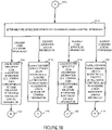
- FIG. 5 is a flowchart 1100 of an exemplary method of operating an exemplary communications device implemented in accordance with the present invention, e.g., WT 1000, to perform encoding and decoding in accordance with the present invention. Operation starts in step 1102, in which the WT 1000 is powered on and initialized. Operation proceeds from step 1102 to steps 1104, 1106, and steps 1108.
- WT 1000 exemplary communications device implemented in accordance with the present invention
- the WT 1000 is operated to receive encoding/decoding information and/or generate control information from received data.
- the encoding/decoding information e.g., control information for the programmable LDPC encoder 1012 and/or programmable LDPC decoder, may be received via a received signal processed through receiver 1002 and/or as user input received via user I/O devices 1015.
- received encoded data may be processed to generate control information. For example, multiple attempts at decoding can be performed using different code structure information and/or different codeword lengths.
- control information is generated in some embodiments indicating the code structure and/or codeword length which is to be used to decode incoming data and, in some embodiments encode outgoing data as well.
- step 1112 the WT 1000 is operated to determine the type of received encoding/decoding control information. Based upon the determination of step 1112, operation proceeds to step 1114, 1116, 1118, or 1120.
- step 1112 If it is determined in step 1112, that the type of control information is encoder code structure information, then operation proceeds to step 1114.
- step 1114 the WT 1000 is operated to load the encoder 1012 with a set of code description information, e.g., control code corresponding to the code structure information indicated by the control information. Operation proceeds from step 1114 to connecting node B 1122.
- step 1112 If it is determined in step 1112, that the type of information is encoder codeword length information, then operation proceeds to step 1116.
- step 1116 the WT 1000 is operated to supply the encoder 1012 with codeword length indicator, e.g., selected lifting factor, corresponding to the codeword length indicated by the control information. Operation proceeds from step 1116 to connecting node B 1122.
- codeword length indicator e.g., selected lifting factor
- step 1112 If it is determined in step 1112, that the type of control information is decoder code structure information, then operation proceeds to step 1118.
- step 1118 the WT 1000 is operated to load the decoder 1006 with a set of code description information, e.g., control code corresponding to the code structure indicated by the control information. Operation proceeds from step 1118 to connecting node B 1122.
- step 1112 If it is determined in step 1112, that the type of information is decoder codeword length information, then operation proceeds to step 1120.
- step 1120 the WT 1000 is operated to supply the decoder 1006 with codeword length indicator, e.g., selected lifting factor, corresponding to indicate codeword length. Operation proceeds from step 1120 to connecting node B 1122.
- codeword length indicator e.g., selected lifting factor
- step 1104 WT 1104 waits to receive other encoding/decoding information, e.g., information to complete the configuration of the programmable decoder 1006 and/or programmable encoder 1012, and/or information to change selected settings, e.g., codeword length settings, of the decoder 1006 and/or encoder 1012.
- other encoding/decoding information e.g., information to complete the configuration of the programmable decoder 1006 and/or programmable encoder 1012, and/or information to change selected settings, e.g., codeword length settings, of the decoder 1006 and/or encoder 1012.
- step 1106 the WT 1000 including a previously configured programmable decoder 1006 is operated to receive through receiver 1002 data to be decoded, e.g., encoded user data from a peer node of WT 1000.
- the received data is forwarded to the decoder 1006.
- step 1124 the decoder 1006 is operated to decode data according to stored code description information in decoder 1006 and codeword length indicator information that has been supplied to the decoder. Operation proceeds from step 1124 to step 1106, where additional data to be decoded is received.
- step 1108 the WT 1000 including a previously configured programmable encoder 1012 is operated to receive through user I/O devices 1015 data to be encoded, e.g., input data from the user of WT 1000 intended to be encoded and communicated to a peer node of WT 1000.
- the received data is forwarded to the encoder 1012.
- step 1108 the encoder 1012 is operated to encode data according to stored code description information and codeword length indicator information supplied to the encoder. Operation proceeds from step 1126 to step 1108, where additional data to be encoded is received.
- the codeword length can, and in various implementations will, change as the wireless terminal switches from receiving data corresponding to a first device and/or application to processing data corresponding to second device and/or application.
- the code structure information used by the encoder 1012 and/or decoder 1006 can be changed over time as the wireless terminal interacts with a different device and/or implements a different application.
- the encoder and decoder may process codewords corresponding to a first length and/or code structure and at another time processes codewords corresponding to a second length and/or code structure.
- the programmable LDPC encoders 1012 and decoders 1006 of the present invention may use other code structures and/or codeword lengths.
- the various supported codeword lengths will normally be up to a maximum size determined by the amount of memory available and/or number and size of available registers in the encoder 1012 and decoder 1006.
- modules used to implement the present invention may be implemented as software, hardware, or as a combination of software and hardware.
- various features of the present invention may be implemented in hardware and/or software.
- some aspects of the invention may be implemented as processor executed program instructions.
- some aspects of the present invention may be implemented as integrated circuits, such as ASICs for example.
- the apparatus of the present invention are directed to software, hardware and/or a combination of software and hardware.
- Machine readable medium including instructions used to control a machine to implement one or more method steps in accordance with the invention are contemplated and to be considered within the scope of some embodiments of the invention.
- the present invention is directed to, among other things, software which can be used to control a processor to perform encoding and/or decoding in accordance with the present invention.
- the methods and apparatus of the present invention may be used with OFDM communications systems as well as with other types of communications systems including CDMA systems.
Landscapes
- Physics & Mathematics (AREA)
- Probability & Statistics with Applications (AREA)
- Engineering & Computer Science (AREA)
- Theoretical Computer Science (AREA)
- Mathematical Physics (AREA)
- Error Detection And Correction (AREA)
- Compression, Expansion, Code Conversion, And Decoders (AREA)
Claims (16)
- Codeur de contrôle de parité à faible densité (LDPC) (300) destiné à coder des mots de code à l'aide d'un code de LDPC élevé avec un facteur d'élévation Z, comprenant :un module de mémoire (302) comportant au moins N x L x K emplacements de stockage, où N et L sont des entiers positifs et K est un entier >1, dans lequel N est le parallélisme de mise en œuvre du codeur, K indique le nombre total de N x L blocs de bits dans le module de mémoire et L est la longueur d'un bloc de bits dans le module de mémoire ;un module de permutation commandable (304) configuré pour effectuer des opérations de réorganisation d'éléments sur au moins N éléments, dans lequel ledit module de permutation commandable est relié audit module de mémoire ;un module d'accumulateurs de vecteurs (306) comportant N accumulateurs agencés en parallèle, ledit module d'accumulateurs de vecteurs comportant :i) une première entrée large d'au moins N bits, dans lequel ladite première entrée est reliée à une sortie dudit module de permutation commandable,ii) une deuxième entrée large d'au moins N bits, etiii) une sortie d'accumulateur de vecteurs large d'au moins N bits ;un dispositif de stockage commandable (308) comportant :(i) N x K emplacements de stockage ;(ii) une entrée de signal de commande de sélection de blocs configurée pour recevoir un signal indiquant un bloc d'au moins N emplacements de stockage auxquels accéder ; et(iii) une sortie du dispositif de stockage large d'au moins N bits, dans lequel ladite sortie du dispositif de stockage est configurée pour fournir en sortie des valeurs lues à partir dudit dispositif de stockage commandable ; etun module de sélection de blocs sur la base d'une élévation de code (310) relié audit dispositif de stockage commandable, dans lequel ledit module de sélection de blocs est configuré pour fournir un signal de commande de sélection de blocs audit dispositif de stockage commandable,dans lequel le parallélisme de mise en œuvre N est le facteur d'élévation Z divisé par K.
- Codeur (300) selon la revendication 1, comprenant en outre :
un module de commande (312) configuré pour générer un premier signal de commande de module de sélection (354) en fonction de l'opération de codage à effectuer, dans lequel ledit premier signal de commande de module de sélection est fourni en tant que première entrée du signal de commande audit module de sélection de blocs sur la base d'une élévation de code (310). - Codeur (300) selon la revendication 2,dans lequel ledit module de sélection de blocs sur la base d'une élévation de code (310) est configuré pour générer ledit signal de commande de sélection de blocs en fonction d'un facteur d'élévation de code ; etdans lequel ledit module de commande est configuré en outre pour générer un signal de commande de réorganisation fourni à une entrée de commande de réorganisation dudit module de permutation commandable.
- Codeur (300) selon la revendication 2, comprenant en outre :
un bus, d'une largeur d'au moins N bits, dans lequel ledit bus est configuré pour relier ledit module de mémoire audit module de permutation commandable. - Codeur (300) selon la revendication 3, dans lequel ledit module de sélection de blocs sur la base d'une élévation de code comporte en outre une sortie de sélection d'adresse de bloc (358) reliée à une entrée correspondante dudit module de mémoire (302) .
- Codeur (300) selon la revendication 3, dans lequel ledit module de sélection de blocs sur la base d'une élévation de code comporte en outre une deuxième entrée de commande du module de sélection (356), dans lequel ladite deuxième entrée de commande du module de sélection est configurée pour recevoir un signal indiquant ledit facteur d'élévation de code à utiliser.
- Codeur (300) selon la revendication 6, dans lequel ledit module de commande (312) est en outre configuré pour générer un signal de commande d'adresse mémoire (350) et fournir ledit signal de commande d'adresse mémoire audit module de mémoire (302) .
- Codeur (300) selon la revendication 7, dans lequel ledit module de mémoire (302) comporte une logique d'adressage (316) pour générer un signal d'accès à la mémoire à partir dudit signal de commande d'adresse de mémoire et dudit signal de sélection d'adresse de bloc.
- Codeur (300) selon la revendication 8,dans lequel ledit dispositif de stockage commandable (308) comporte en outre une entrée de commande de lecture/écriture ; etdans lequel le module de commande (312) comprend en outre une sortie du signal de commande de lecture/écriture reliée à l'entrée de commande de lecture/écriture dudit dispositif de stockage commandable.
- Codeur (300) selon la revendication 1, dans lequel la sortie du dispositif de stockage dudit dispositif de stockage commandable (308) est reliée à ladite deuxième entrée dudit module module d'accumulateurs de vecteurs (306) et à une entrée dudit module de mémoire.
- Codeur (300) selon la revendication 9, dans lequel ladite sortie du signal de commande de lecture/écriture est en outre reliée à une entrée correspondante dudit module de mémoire.
- Codeur (300) selon la revendication 7, dans lequel ledit module de commande (312) est en outre configuré pour générer le signal de commande d'adresse mémoire sous forme d'une valeur entière supérieure à 0 et inférieure à L+1, et ledit module de commande est en outre configuré pour parcourir chaque valeur entière représentée de 1 à L pendant une opération de codage, où L est un entier positif.
- Procédé d'exécution d'un traitement de codage de contrôle de parité à faible densité (LDPC), comprenant :la fourniture d'un codeur (300) destiné à coder des mots de code à l'aide d'un code de LDPC élevé avec un facteur d'élévation Z, ledit codeur comportant :un module de mémoire (302) comportant au moins N x L x K emplacements de stockage, où N et L sont des entiers positifs et K est un entier >1, dans lequel N est le parallélisme de mise en œuvre du codeur, K indique le nombre total de N x L blocs de bits dans le module de mémoire et L est la longueur d'un bloc de bits dans le module de mémoire ;un module de permutation commandable (304) configuré pour effectuer des opérations de réorganisation d'éléments sur au moins N éléments, dans lequel ledit module de permutation commandable est relié audit module de mémoire ;un module d'accumulateurs de vecteurs (306) comportant N accumulateurs agencés en parallèle, ledit module d'accumulateurs de vecteurs comportant :i) une première entrée large d'au moins N bits, dans lequel ladite première entrée est reliée à une sortie dudit module de permutation commandable,ii) une deuxième entrée large d'au moins N bits, etiii) une sortie d'accumulateur de vecteurs large d'au moins N bits ;un dispositif de stockage commandable (308) comportant :(i) N x K emplacements de stockage ;(ii) une entrée de signal de commande de sélection de blocs configurée pour recevoir un signal indiquant un bloc d'au moins N emplacements de stockage auxquels accéder ; et(iii) une sortie du dispositif de stockage large d'au moins N bits, dans lequel ladite sortie du dispositif de stockage est configurée pour fournir en sortie des valeurs lues à partir dudit dispositif de stockage commandable ; etun module de sélection de blocs sur la base d'une élévation de code (310) relié audit dispositif de stockage commandable, dans lequel ledit module de sélection de blocs est configuré pour fournir un signal de commande de sélection de blocs audit dispositif de stockage commandable,dans lequel le parallélisme de mise en œuvre N est le facteur d'élévation Z divisé par K ;la génération d'un premier signal de commande de module de sélection (354) en fonction d'une description de code stockée et d'un signal d'horloge utilisé pour commander la synchronisation d'opérations de codage ;la fourniture dudit premier signal de commande de module de sélection (354) audit module de sélection de blocs sur la base d'une élévation de code (310) ; etl'actionnement du module de sélection de blocs sur la base d'une élévation de code (310) pour sélectionner un bloc d'emplacements mémoire auxquels accéder dans ledit dispositif de stockage commandable (308) en fonction dudit premier signal de commande de module de sélection.
- Procédé selon la revendication 13, comprenant en outre :la génération d'un signal de commande de réorganisation ;la fourniture du signal de commande de réorganisation audit module de permutation (304) ; etl'actionnement du module de permutation pour effectuer une opération de réorganisation de messages conformément audit signal de commande de réorganisation fourni.
- Procédé selon la revendication 14, comprenant en outre :l'actionnement dudit module de sélection de blocs sur la base d'une élévation de code (310) pour générer un signal de sélection d'adresse de bloc en fonction d'informations de description de code stockées ; etla fourniture dudit signal de sélection d'adresse de bloc audit module de mémoire (302) pour l'utiliser dans la détermination d'un ensemble d'emplacements de mémoire auxquels accéder.
- Produit programme d'ordinateur comprenant un support lisible par ordinateur, le support lisible par ordinateur comprenant au moins une instruction pour amener un ordinateur ou un processeur à mettre en œuvre un procédé selon l'une quelconque des revendications 13 à 15.
Applications Claiming Priority (2)
| Application Number | Priority Date | Filing Date | Title |
|---|---|---|---|
| US10/895,547 US7346832B2 (en) | 2004-07-21 | 2004-07-21 | LDPC encoding methods and apparatus |
| PCT/US2005/025752 WO2006014742A2 (fr) | 2004-07-21 | 2005-07-20 | Procedes et dispositif de codage ldpc |
Publications (3)
| Publication Number | Publication Date |
|---|---|
| EP1787397A2 EP1787397A2 (fr) | 2007-05-23 |
| EP1787397A4 EP1787397A4 (fr) | 2010-07-28 |
| EP1787397B1 true EP1787397B1 (fr) | 2022-11-16 |
Family
ID=35658679
Family Applications (1)
| Application Number | Title | Priority Date | Filing Date |
|---|---|---|---|
| EP05775250.3A Expired - Lifetime EP1787397B1 (fr) | 2004-07-21 | 2005-07-20 | Procedes et dispositif de codage ldpc |
Country Status (12)
| Country | Link |
|---|---|
| US (2) | US7346832B2 (fr) |
| EP (1) | EP1787397B1 (fr) |
| KR (2) | KR100905814B1 (fr) |
| CN (3) | CN101917199B (fr) |
| AU (3) | AU2005269729B2 (fr) |
| CA (2) | CA2577793C (fr) |
| NO (1) | NO20070970L (fr) |
| NZ (1) | NZ553354A (fr) |
| RU (1) | RU2395902C2 (fr) |
| UA (1) | UA91513C2 (fr) |
| WO (1) | WO2006014742A2 (fr) |
| ZA (1) | ZA200701497B (fr) |
Families Citing this family (146)
| Publication number | Priority date | Publication date | Assignee | Title |
|---|---|---|---|---|
| US7346832B2 (en) * | 2004-07-21 | 2008-03-18 | Qualcomm Incorporated | LDPC encoding methods and apparatus |
| EP1800405B1 (fr) * | 2004-09-17 | 2014-03-12 | LG Electronics Inc. | Codage et décodage de codes LDPC utilisant des matrices de contrôle de parité structurées |
| US7900127B2 (en) * | 2005-01-10 | 2011-03-01 | Broadcom Corporation | LDPC (Low Density Parity Check) codes with corresponding parity check matrices selectively constructed with CSI (Cyclic Shifted Identity) and null sub-matrices |
| KR101102396B1 (ko) * | 2006-02-08 | 2012-01-05 | 엘지전자 주식회사 | 이동통신 시스템에서의 코드워드 크기 정합 방법 및 송신장치 |
| US7801200B2 (en) * | 2006-07-31 | 2010-09-21 | Agere Systems Inc. | Systems and methods for code dependency reduction |
| US7802163B2 (en) * | 2006-07-31 | 2010-09-21 | Agere Systems Inc. | Systems and methods for code based error reduction |
| US7779331B2 (en) | 2006-07-31 | 2010-08-17 | Agere Systems Inc. | Systems and methods for tri-column code based error reduction |
| US20080059869A1 (en) * | 2006-09-01 | 2008-03-06 | The Regents Of The University Of California | Low cost, high performance error detection and correction |
| US20080155148A1 (en) * | 2006-10-26 | 2008-06-26 | Ozgur Oyman | Cooperative communication of data |
| US7971125B2 (en) * | 2007-01-08 | 2011-06-28 | Agere Systems Inc. | Systems and methods for prioritizing error correction data |
| KR20090113869A (ko) | 2007-01-24 | 2009-11-02 | 콸콤 인코포레이티드 | 가변 크기들의 패킷들의 ldpc 인코딩 및 디코딩 |
| US8418023B2 (en) | 2007-05-01 | 2013-04-09 | The Texas A&M University System | Low density parity check decoder for irregular LDPC codes |
| US7930621B2 (en) | 2007-06-01 | 2011-04-19 | Agere Systems Inc. | Systems and methods for LDPC decoding with post processing |
| US8196002B2 (en) * | 2007-06-01 | 2012-06-05 | Agere Systems Inc. | Systems and methods for joint LDPC encoding and decoding |
| JP2010541375A (ja) * | 2007-09-28 | 2010-12-24 | アギア システムズ インコーポレーテッド | 複雑度を低減したデータ処理のためのシステムおよび方法 |
| US8473824B1 (en) * | 2008-09-08 | 2013-06-25 | Marvell International Ltd. | Quasi-cyclic low-density parity-check (QC-LDPC) encoder |
| US8095859B1 (en) * | 2008-01-09 | 2012-01-10 | L-3 Communications, Corp. | Encoder for low-density parity check codes |
| US8161348B2 (en) * | 2008-02-05 | 2012-04-17 | Agere Systems Inc. | Systems and methods for low cost LDPC decoding |
| US8245104B2 (en) * | 2008-05-02 | 2012-08-14 | Lsi Corporation | Systems and methods for queue based data detection and decoding |
| KR101460835B1 (ko) * | 2008-05-19 | 2014-11-11 | 에이저 시스템즈 엘엘시 | 데이터 검출기 피드백 루프에서 레이턴시를 완화하는 시스템들 및 방법들 |
| US8166364B2 (en) * | 2008-08-04 | 2012-04-24 | Seagate Technology Llc | Low density parity check decoder using multiple variable node degree distribution codes |
| US8660220B2 (en) * | 2008-09-05 | 2014-02-25 | Lsi Corporation | Reduced frequency data processing using a matched filter set front end |
| US8245120B2 (en) * | 2008-09-17 | 2012-08-14 | Lsi Corporation | Power reduced queue based data detection and decoding systems and methods for using such |
| US8261166B2 (en) * | 2008-09-17 | 2012-09-04 | Seagate Technology Llc | Node processor for use with low density parity check decoder using multiple variable node degree distribution codes |
| US8321752B1 (en) * | 2008-11-12 | 2012-11-27 | Marvell International Ltd. | Integrated 2-level low density parity check (LDPC) codes |
| CN102037513A (zh) * | 2008-11-20 | 2011-04-27 | Lsi公司 | 用于噪声降低的数据检测的系统和方法 |
| US7990642B2 (en) * | 2009-04-17 | 2011-08-02 | Lsi Corporation | Systems and methods for storage channel testing |
| US8443267B2 (en) * | 2009-04-28 | 2013-05-14 | Lsi Corporation | Systems and methods for hard decision assisted decoding |
| US8250434B2 (en) * | 2009-06-18 | 2012-08-21 | Lsi Corporation | Systems and methods for codec usage control during storage pre-read |
| US8352841B2 (en) * | 2009-06-24 | 2013-01-08 | Lsi Corporation | Systems and methods for out of order Y-sample memory management |
| US8312343B2 (en) * | 2009-07-28 | 2012-11-13 | Lsi Corporation | Systems and methods for re-using decoding parity in a detector circuit |
| US8458553B2 (en) | 2009-07-28 | 2013-06-04 | Lsi Corporation | Systems and methods for utilizing circulant parity in a data processing system |
| US8321746B2 (en) | 2009-07-30 | 2012-11-27 | Lsi Corporation | Systems and methods for quasi-cyclic LDPC code production and decoding |
| US8250431B2 (en) * | 2009-07-30 | 2012-08-21 | Lsi Corporation | Systems and methods for phase dependent data detection in iterative decoding |
| US8266505B2 (en) | 2009-08-12 | 2012-09-11 | Lsi Corporation | Systems and methods for retimed virtual data processing |
| US8176404B2 (en) * | 2009-09-09 | 2012-05-08 | Lsi Corporation | Systems and methods for stepped data retry in a storage system |
| US8880976B2 (en) * | 2009-09-25 | 2014-11-04 | Stmicroelectronics, Inc. | Method and apparatus for encoding LBA information into the parity of a LDPC system |
| US8688873B2 (en) | 2009-12-31 | 2014-04-01 | Lsi Corporation | Systems and methods for monitoring out of order data decoding |
| US8578253B2 (en) | 2010-01-04 | 2013-11-05 | Lsi Corporation | Systems and methods for updating detector parameters in a data processing circuit |
| US8683306B2 (en) * | 2010-01-04 | 2014-03-25 | Lsi Corporation | Systems and methods for data detection including dynamic scaling |
| US8743936B2 (en) * | 2010-01-05 | 2014-06-03 | Lsi Corporation | Systems and methods for determining noise components in a signal set |
| US8572463B2 (en) * | 2010-02-01 | 2013-10-29 | Sk Hynix Memory Solutions Inc. | Quasi-cyclic LDPC encoding and decoding for non-integer multiples of circulant size |
| US8448041B1 (en) * | 2010-02-01 | 2013-05-21 | Sk Hynix Memory Solutions Inc. | Multistage LDPC encoding |
| US8443257B1 (en) | 2010-02-01 | 2013-05-14 | Sk Hynix Memory Solutions Inc. | Rate-scalable, multistage quasi-cyclic LDPC coding |
| US8504894B1 (en) | 2010-03-04 | 2013-08-06 | Sk Hynix Memory Solutions Inc. | Systematic encoding for non-full row rank, quasi-cyclic LDPC parity check matrices |
| CN101800627B (zh) * | 2010-03-16 | 2012-12-05 | 北京海格神舟通信科技有限公司 | 一种多码率兼容的高速ldpc编码器的硬件实现 |
| US8161351B2 (en) | 2010-03-30 | 2012-04-17 | Lsi Corporation | Systems and methods for efficient data storage |
| US9343082B2 (en) | 2010-03-30 | 2016-05-17 | Avago Technologies General Ip (Singapore) Pte. Ltd. | Systems and methods for detecting head contact |
| US8418019B2 (en) | 2010-04-19 | 2013-04-09 | Lsi Corporation | Systems and methods for dynamic scaling in a data decoding system |
| US8443249B2 (en) | 2010-04-26 | 2013-05-14 | Lsi Corporation | Systems and methods for low density parity check data encoding |
| US8527831B2 (en) | 2010-04-26 | 2013-09-03 | Lsi Corporation | Systems and methods for low density parity check data decoding |
| US8381071B1 (en) | 2010-05-21 | 2013-02-19 | Lsi Corporation | Systems and methods for decoder sharing between data sets |
| US8381074B1 (en) | 2010-05-21 | 2013-02-19 | Lsi Corporation | Systems and methods for utilizing a centralized queue based data processing circuit |
| US8208213B2 (en) | 2010-06-02 | 2012-06-26 | Lsi Corporation | Systems and methods for hybrid algorithm gain adaptation |
| US8979860B2 (en) | 2010-06-24 | 2015-03-17 | DePuy Synthes Products. LLC | Enhanced cage insertion device |
| US8379498B2 (en) | 2010-09-13 | 2013-02-19 | Lsi Corporation | Systems and methods for track to track phase alignment |
| US9219469B2 (en) | 2010-09-21 | 2015-12-22 | Avago Technologies General Ip (Singapore) Pte. Ltd. | Systems and methods for filter constraint estimation |
| US8295001B2 (en) | 2010-09-21 | 2012-10-23 | Lsi Corporation | Systems and methods for low latency noise cancellation |
| US8443250B2 (en) | 2010-10-11 | 2013-05-14 | Lsi Corporation | Systems and methods for error correction using irregular low density parity check codes |
| US8560930B2 (en) | 2010-10-11 | 2013-10-15 | Lsi Corporation | Systems and methods for multi-level quasi-cyclic low density parity check codes |
| US8385014B2 (en) | 2010-10-11 | 2013-02-26 | Lsi Corporation | Systems and methods for identifying potential media failure |
| US8661071B2 (en) | 2010-10-11 | 2014-02-25 | Lsi Corporation | Systems and methods for partially conditioned noise predictive equalization |
| US8750447B2 (en) | 2010-11-02 | 2014-06-10 | Lsi Corporation | Systems and methods for variable thresholding in a pattern detector |
| US8667039B2 (en) | 2010-11-17 | 2014-03-04 | Lsi Corporation | Systems and methods for variance dependent normalization for branch metric calculation |
| US8566379B2 (en) | 2010-11-17 | 2013-10-22 | Lsi Corporation | Systems and methods for self tuning target adaptation |
| CN103155420B (zh) | 2011-01-07 | 2017-10-27 | 马维尔国际贸易有限公司 | 用于并联布置的多个迭代解码器的低延时simd架构 |
| KR101611169B1 (ko) * | 2011-01-18 | 2016-04-11 | 삼성전자주식회사 | 통신/방송 시스템에서 데이터 송수신 장치 및 방법 |
| US8810940B2 (en) | 2011-02-07 | 2014-08-19 | Lsi Corporation | Systems and methods for off track error recovery |
| US8699167B2 (en) | 2011-02-16 | 2014-04-15 | Lsi Corporation | Systems and methods for data detection using distance based tuning |
| US8446683B2 (en) | 2011-02-22 | 2013-05-21 | Lsi Corporation | Systems and methods for data pre-coding calibration |
| US8854753B2 (en) | 2011-03-17 | 2014-10-07 | Lsi Corporation | Systems and methods for auto scaling in a data processing system |
| US8693120B2 (en) | 2011-03-17 | 2014-04-08 | Lsi Corporation | Systems and methods for sample averaging in data processing |
| US8887034B2 (en) | 2011-04-15 | 2014-11-11 | Lsi Corporation | Systems and methods for short media defect detection |
| US8611033B2 (en) | 2011-04-15 | 2013-12-17 | Lsi Corporation | Systems and methods for selective decoder input data processing |
| US8670955B2 (en) | 2011-04-15 | 2014-03-11 | Lsi Corporation | Systems and methods for reliability assisted noise predictive filtering |
| US8560929B2 (en) | 2011-06-24 | 2013-10-15 | Lsi Corporation | Systems and methods for non-binary decoding |
| US8566665B2 (en) | 2011-06-24 | 2013-10-22 | Lsi Corporation | Systems and methods for error correction using low density parity check codes using multiple layer check equations |
| US8499231B2 (en) | 2011-06-24 | 2013-07-30 | Lsi Corporation | Systems and methods for reduced format non-binary decoding |
| US8879182B2 (en) | 2011-07-19 | 2014-11-04 | Lsi Corporation | Storage media inter-track interference cancellation |
| US8830613B2 (en) | 2011-07-19 | 2014-09-09 | Lsi Corporation | Storage media inter-track interference cancellation |
| US8819527B2 (en) | 2011-07-19 | 2014-08-26 | Lsi Corporation | Systems and methods for mitigating stubborn errors in a data processing system |
| US8539328B2 (en) | 2011-08-19 | 2013-09-17 | Lsi Corporation | Systems and methods for noise injection driven parameter selection |
| US8854754B2 (en) | 2011-08-19 | 2014-10-07 | Lsi Corporation | Systems and methods for local iteration adjustment |
| US9026572B2 (en) | 2011-08-29 | 2015-05-05 | Lsi Corporation | Systems and methods for anti-causal noise predictive filtering in a data channel |
| US8661324B2 (en) | 2011-09-08 | 2014-02-25 | Lsi Corporation | Systems and methods for non-binary decoding biasing control |
| US8681441B2 (en) | 2011-09-08 | 2014-03-25 | Lsi Corporation | Systems and methods for generating predictable degradation bias |
| US8850276B2 (en) | 2011-09-22 | 2014-09-30 | Lsi Corporation | Systems and methods for efficient data shuffling in a data processing system |
| US8767333B2 (en) | 2011-09-22 | 2014-07-01 | Lsi Corporation | Systems and methods for pattern dependent target adaptation |
| US8479086B2 (en) | 2011-10-03 | 2013-07-02 | Lsi Corporation | Systems and methods for efficient parameter modification |
| US8578241B2 (en) | 2011-10-10 | 2013-11-05 | Lsi Corporation | Systems and methods for parity sharing data processing |
| US8689062B2 (en) | 2011-10-03 | 2014-04-01 | Lsi Corporation | Systems and methods for parameter selection using reliability information |
| US8862960B2 (en) | 2011-10-10 | 2014-10-14 | Lsi Corporation | Systems and methods for parity shared data encoding |
| US8527858B2 (en) | 2011-10-28 | 2013-09-03 | Lsi Corporation | Systems and methods for selective decode algorithm modification |
| US8683309B2 (en) | 2011-10-28 | 2014-03-25 | Lsi Corporation | Systems and methods for ambiguity based decode algorithm modification |
| US8443271B1 (en) | 2011-10-28 | 2013-05-14 | Lsi Corporation | Systems and methods for dual process data decoding |
| US8751913B2 (en) | 2011-11-14 | 2014-06-10 | Lsi Corporation | Systems and methods for reduced power multi-layer data decoding |
| US8531320B2 (en) | 2011-11-14 | 2013-09-10 | Lsi Corporation | Systems and methods for memory efficient data decoding |
| US8954822B2 (en) * | 2011-11-18 | 2015-02-10 | Sandisk Enterprise Ip Llc | Data encoder and decoder using memory-specific parity-check matrix |
| US9203434B1 (en) | 2012-03-09 | 2015-12-01 | Western Digital Technologies, Inc. | Systems and methods for improved encoding of data in data storage devices |
| KR101840252B1 (ko) * | 2012-03-12 | 2018-03-20 | 에스케이하이닉스 주식회사 | 저밀도 패리티 검사 부호용 장치 |
| US8605383B1 (en) | 2012-05-21 | 2013-12-10 | Western Digital Technologies, Inc. | Methods, devices and systems for characterizing polarities of piezoelectric (PZT) elements of a two PZT element microactuator |
| CN106899311B (zh) * | 2012-09-24 | 2023-11-03 | 华为技术有限公司 | 混合极性码的生成方法和生成装置 |
| US8972826B2 (en) | 2012-10-24 | 2015-03-03 | Western Digital Technologies, Inc. | Adaptive error correction codes for data storage systems |
| US9021339B2 (en) | 2012-11-29 | 2015-04-28 | Western Digital Technologies, Inc. | Data reliability schemes for data storage systems |
| US9059736B2 (en) | 2012-12-03 | 2015-06-16 | Western Digital Technologies, Inc. | Methods, solid state drive controllers and data storage devices having a runtime variable raid protection scheme |
| US8966339B1 (en) | 2012-12-18 | 2015-02-24 | Western Digital Technologies, Inc. | Decoder supporting multiple code rates and code lengths for data storage systems |
| US9122625B1 (en) | 2012-12-18 | 2015-09-01 | Western Digital Technologies, Inc. | Error correcting code encoder supporting multiple code rates and throughput speeds for data storage systems |
| US9619317B1 (en) | 2012-12-18 | 2017-04-11 | Western Digital Technologies, Inc. | Decoder having early decoding termination detection |
| US9214963B1 (en) | 2012-12-21 | 2015-12-15 | Western Digital Technologies, Inc. | Method and system for monitoring data channel to enable use of dynamically adjustable LDPC coding parameters in a data storage system |
| US8797664B1 (en) | 2012-12-22 | 2014-08-05 | Western Digital Technologies, Inc. | Polarity detection of piezoelectric actuator in disk drive |
| BR112015019409B1 (pt) * | 2013-02-13 | 2022-01-11 | Qualcomm Incorporated | Projeto de ldpc utilizando construções quase-cíclicas e perfuração para alta taxa, alto paralelismo, e piso de erro baixo |
| US9705532B2 (en) * | 2013-03-15 | 2017-07-11 | Arris Enterprises Llc | Parallel low-density parity check (LDPC) accumulation |
| US9513989B2 (en) * | 2013-03-26 | 2016-12-06 | Seagate Technology Llc | Priori information based post-processing in low-density parity-check code decoders |
| CN105144589B (zh) * | 2013-05-02 | 2019-06-28 | 索尼公司 | 数据处理装置以及数据处理方法 |
| EP3054599B1 (fr) | 2013-11-11 | 2020-11-04 | Huawei Technologies Co., Ltd. | Méthode et dispositif d'encodage par code polaire |
| WO2015139316A1 (fr) * | 2014-03-21 | 2015-09-24 | 华为技术有限公司 | Procédé et dispositif de retransmission de code polaire |
| RU2571587C2 (ru) * | 2014-04-10 | 2015-12-20 | Самсунг Электроникс Ко., Лтд. | Способ и устройство кодирования и декодирования данных в скрученном полярном коде |
| CN107437948B (zh) * | 2014-09-17 | 2020-08-07 | 上海数字电视国家工程研究中心有限公司 | 针对低码率ldpc码的校验矩阵及编码方法 |
| US9153283B1 (en) | 2014-09-30 | 2015-10-06 | Western Digital Technologies, Inc. | Data storage device compensating for hysteretic response of microactuator |
| CN104917588A (zh) * | 2015-04-13 | 2015-09-16 | 李焱 | 提高非视距毫米波室内通信系统传输可靠性信道编码方法 |
| WO2017063263A1 (fr) | 2015-10-13 | 2017-04-20 | 华为技术有限公司 | Dispositif et procédé de décodage, et système de transmission de signal |
| US10784901B2 (en) | 2015-11-12 | 2020-09-22 | Qualcomm Incorporated | Puncturing for structured low density parity check (LDPC) codes |
| US11043966B2 (en) | 2016-05-11 | 2021-06-22 | Qualcomm Incorporated | Methods and apparatus for efficiently generating multiple lifted low-density parity-check (LDPC) codes |
| US10454499B2 (en) | 2016-05-12 | 2019-10-22 | Qualcomm Incorporated | Enhanced puncturing and low-density parity-check (LDPC) code structure |
| US9917675B2 (en) | 2016-06-01 | 2018-03-13 | Qualcomm Incorporated | Enhanced polar code constructions by strategic placement of CRC bits |
| US10313057B2 (en) | 2016-06-01 | 2019-06-04 | Qualcomm Incorporated | Error detection in wireless communications using sectional redundancy check information |
| US10469104B2 (en) | 2016-06-14 | 2019-11-05 | Qualcomm Incorporated | Methods and apparatus for compactly describing lifted low-density parity-check (LDPC) codes |
| JP6798004B2 (ja) * | 2016-07-20 | 2020-12-09 | ホアウェイ・テクノロジーズ・カンパニー・リミテッド | Ldpc符号の符号化および復号化のための方法およびシステム |
| US20210281359A1 (en) | 2016-07-27 | 2021-09-09 | Qualcomm Incorporated | Design of hybrid automatic repeat request (harq) feedback bits for polar codes |
| PL3308469T3 (pl) | 2016-08-12 | 2020-08-24 | Telefonaktiebolaget Lm Ericsson (Publ) | Sposoby dopasowywania szybkości dla kodów LDPC |
| US10243638B2 (en) | 2016-10-04 | 2019-03-26 | At&T Intellectual Property I, L.P. | Forward error correction code selection in wireless systems |
| US10270559B2 (en) | 2016-10-04 | 2019-04-23 | At&T Intellectual Property I, L.P. | Single encoder and decoder for forward error correction coding |
| CN110024295B (zh) * | 2016-11-14 | 2021-02-12 | 华为技术有限公司 | 可变长度准循环低密度奇偶校验qc-ldpc码的编、解码方法和装置 |
| CN108111251B (zh) * | 2016-11-24 | 2020-11-06 | 上海交通大学 | 应用于广播通信系统的信令码编码方法及对应的译码方法 |
| CN108400838B (zh) * | 2017-02-06 | 2021-05-18 | 华为技术有限公司 | 数据处理方法及设备 |
| KR102262186B1 (ko) | 2017-03-03 | 2021-06-08 | 후아웨이 테크놀러지 컴퍼니 리미티드 | 높은 레이트의 긴 ldpc 코드 |
| CN110583023B (zh) | 2017-05-04 | 2022-03-01 | 三星电子株式会社 | 在通信或广播系统中用于信道编码和解码的方法和设备 |
| KR102302366B1 (ko) * | 2017-05-04 | 2021-09-16 | 삼성전자 주식회사 | 통신 또는 방송 시스템에서 채널 부호화/복호화 방법 및 장치 |
| US10312939B2 (en) | 2017-06-10 | 2019-06-04 | Qualcomm Incorporated | Communication techniques involving pairwise orthogonality of adjacent rows in LPDC code |
| US12476733B2 (en) | 2017-06-19 | 2025-11-18 | Qualcomm Incorporated | Communication techniques with self-decodable redundancy versions (RVs) using systematic codes |
| US10940016B2 (en) | 2017-07-05 | 2021-03-09 | Medos International Sarl | Expandable intervertebral fusion cage |
| EP3649755B1 (fr) | 2017-07-07 | 2023-09-20 | QUALCOMM Incorporated | Techniques de communication appliquant une sélection de graphe de base pour un code de contrôle de parité à faible densité |
| CN116054843A (zh) * | 2017-09-11 | 2023-05-02 | 中兴通讯股份有限公司 | 处理ldpc编码数据的方法和装置 |
| CN113014270B (zh) * | 2021-02-22 | 2022-08-05 | 上海大学 | 码长可配置的部分折叠极化码译码器 |
| CN113300717B (zh) * | 2021-05-19 | 2022-06-10 | 西南交通大学 | 一种基于码率自适应的高效化ldpc编码器电路 |
| CN120074545B (zh) * | 2025-01-22 | 2025-11-25 | 西安电子科技大学 | 高吞吐、适配多类码型的qc-ldpc码编码方法及装置 |
Family Cites Families (54)
| Publication number | Priority date | Publication date | Assignee | Title |
|---|---|---|---|---|
| US3542756A (en) | 1968-02-07 | 1970-11-24 | Codex Corp | Error correcting |
| US3665396A (en) | 1968-10-11 | 1972-05-23 | Codex Corp | Sequential decoding |
| US4295218A (en) | 1979-06-25 | 1981-10-13 | Regents Of The University Of California | Error-correcting coding system |
| US5293489A (en) | 1985-01-24 | 1994-03-08 | Nec Corporation | Circuit arrangement capable of centralizing control of a switching network |
| US5271042A (en) | 1989-10-13 | 1993-12-14 | Motorola, Inc. | Soft decision decoding with channel equalization |
| US5157671A (en) | 1990-05-29 | 1992-10-20 | Space Systems/Loral, Inc. | Semi-systolic architecture for decoding error-correcting codes |
| US5313609A (en) | 1991-05-23 | 1994-05-17 | International Business Machines Corporation | Optimum write-back strategy for directory-based cache coherence protocols |
| US5455704A (en) * | 1991-11-08 | 1995-10-03 | Mitsubishi Denki Kabushiki Kaisha | Optical-fiber light amplifier |
| US5396518A (en) | 1993-05-05 | 1995-03-07 | Gi Corporation | Apparatus and method for communicating digital data using trellis coding with punctured convolutional codes |
| US5457704A (en) | 1993-05-21 | 1995-10-10 | At&T Ipm Corp. | Post processing method and apparatus for symbol reliability generation |
| US5526501A (en) | 1993-08-12 | 1996-06-11 | Hughes Aircraft Company | Variable accuracy indirect addressing scheme for SIMD multi-processors and apparatus implementing same |
| US5615298A (en) | 1994-03-14 | 1997-03-25 | Lucent Technologies Inc. | Excitation signal synthesis during frame erasure or packet loss |
| US5860085A (en) | 1994-08-01 | 1999-01-12 | Cypress Semiconductor Corporation | Instruction set for a content addressable memory array with read/write circuits and an interface register logic block |
| CA2156889C (fr) * | 1994-09-30 | 1999-11-02 | Edward L. Schwartz | Methode et appareil de codage et de decodage de donnees |
| US5671221A (en) | 1995-06-14 | 1997-09-23 | Sharp Microelectronics Technology, Inc. | Receiving method and apparatus for use in a spread-spectrum communication system |
| US5867538A (en) | 1995-08-15 | 1999-02-02 | Hughes Electronics Corporation | Computational simplified detection of digitally modulated radio signals providing a detection of probability for each symbol |
| US5721745A (en) * | 1996-04-19 | 1998-02-24 | General Electric Company | Parallel concatenated tail-biting convolutional code and decoder therefor |
| US5968198A (en) | 1996-08-16 | 1999-10-19 | Ericsson, Inc. | Decoder utilizing soft information output to minimize error rates |
| US5892962A (en) | 1996-11-12 | 1999-04-06 | Lucent Technologies Inc. | FPGA-based processor |
| US5909572A (en) | 1996-12-02 | 1999-06-01 | Compaq Computer Corp. | System and method for conditionally moving an operand from a source register to a destination register |
| US6438180B1 (en) | 1997-05-09 | 2002-08-20 | Carnegie Mellon University | Soft and hard sequence detection in ISI memory channels |
| GB2326253A (en) | 1997-06-10 | 1998-12-16 | Advanced Risc Mach Ltd | Coprocessor data access control |
| US5933650A (en) | 1997-10-09 | 1999-08-03 | Mips Technologies, Inc. | Alignment and ordering of vector elements for single instruction multiple data processing |
| US5864703A (en) | 1997-10-09 | 1999-01-26 | Mips Technologies, Inc. | Method for providing extended precision in SIMD vector arithmetic operations |
| US6195777B1 (en) | 1997-11-06 | 2001-02-27 | Compaq Computer Corporation | Loss resilient code with double heavy tailed series of redundant layers |
| US6073250A (en) | 1997-11-06 | 2000-06-06 | Luby; Michael G. | Loss resilient decoding technique |
| US6339834B1 (en) | 1998-05-28 | 2002-01-15 | Her Majesty The Queen In Right Of Canada, As Represented By The Minister Of Industry Through The Communication Research Centre | Interleaving with golden section increments |
| RU2190296C2 (ru) * | 1998-08-20 | 2002-09-27 | Самсунг Электроникс Ко., Лтд. | Устройство и способ вставки заранее известных битов на входном каскаде канального кодера |
| JP2002526965A (ja) | 1998-09-28 | 2002-08-20 | アドバンスト ハードウェア アーキテクチャーズ,インコーポレイテッド | ターボプロダクト符号復号器 |
| WO2000022739A1 (fr) * | 1998-10-13 | 2000-04-20 | Interdigital Technology Corporation | Dispositif d'imbrication hybride pour turbo-codes |
| US6247158B1 (en) | 1998-11-30 | 2001-06-12 | Itt Manufacturing Enterprises, Inc. | Digital broadcasting system and method |
| US6304991B1 (en) | 1998-12-04 | 2001-10-16 | Qualcomm Incorporated | Turbo code interleaver using linear congruential sequence |
| FR2789824B1 (fr) * | 1999-02-12 | 2001-05-11 | Canon Kk | Procede de correction d'erreurs residuelles a la sortie d'un turbo-decodeur |
| US6397240B1 (en) | 1999-02-18 | 2002-05-28 | Agere Systems Guardian Corp. | Programmable accelerator for a programmable processor system |
| US6473010B1 (en) | 2000-04-04 | 2002-10-29 | Marvell International, Ltd. | Method and apparatus for determining error correction code failure rate for iterative decoding algorithms |
| KR20100046063A (ko) * | 2000-06-16 | 2010-05-04 | 어웨어, 인크. | Ldpc 코드형 변조를 위한 시스템 및 방법 |
| US6754804B1 (en) | 2000-12-29 | 2004-06-22 | Mips Technologies, Inc. | Coprocessor interface transferring multiple instructions simultaneously along with issue path designation and/or issue order designation for the instructions |
| US6731700B1 (en) | 2001-01-04 | 2004-05-04 | Comsys Communication & Signal Processing Ltd. | Soft decision output generator |
| US6633856B2 (en) | 2001-06-15 | 2003-10-14 | Flarion Technologies, Inc. | Methods and apparatus for decoding LDPC codes |
| FR2834146A1 (fr) * | 2001-12-20 | 2003-06-27 | St Microelectronics Sa | Turbo-decodeur compact a haute efficacite |
| US6718504B1 (en) | 2002-06-05 | 2004-04-06 | Arc International | Method and apparatus for implementing a data processor adapted for turbo decoding |
| WO2004006442A1 (fr) | 2002-07-03 | 2004-01-15 | Hughes Electronics Corporation | Codage de codes a controle de parite basse densite, par matrice a controle de parite structuree |
| US7178080B2 (en) | 2002-08-15 | 2007-02-13 | Texas Instruments Incorporated | Hardware-efficient low density parity check code for digital communications |
| WO2004019268A1 (fr) * | 2002-08-20 | 2004-03-04 | Flarion Technologies, Inc. | Procédés et appareil permettant de coder des codes ldpc |
| KR20040036460A (ko) * | 2002-10-26 | 2004-04-30 | 삼성전자주식회사 | Ldpc 복호화 장치 및 그 방법 |
| US7702986B2 (en) * | 2002-11-18 | 2010-04-20 | Qualcomm Incorporated | Rate-compatible LDPC codes |
| US7254769B2 (en) * | 2002-12-24 | 2007-08-07 | Electronics And Telecommunications Research Insitute | Encoding/decoding apparatus using low density parity check code |
| KR100550414B1 (ko) * | 2002-12-24 | 2006-02-08 | 한국전자통신연구원 | 하이브리드 재전송 시스템에서 ldpc 부호를 사용하는인코딩 장치 및 디코딩 장치 |
| KR100809619B1 (ko) * | 2003-08-26 | 2008-03-05 | 삼성전자주식회사 | 이동 통신 시스템에서 블록 저밀도 패러티 검사 부호부호화/복호 장치 및 방법 |
| JP4123109B2 (ja) * | 2003-08-29 | 2008-07-23 | 日本ビクター株式会社 | 変調装置及び変調方法並びに復調装置及び復調方法 |
| US7395495B2 (en) * | 2004-01-12 | 2008-07-01 | Intel Corporation | Method and apparatus for decoding forward error correction codes |
| KR100678176B1 (ko) * | 2004-04-28 | 2007-02-28 | 삼성전자주식회사 | 가변 블록 길이를 가지는 블록 저밀도 패리티 검사 부호부호화/복호 장치 및 방법 |
| US7346832B2 (en) * | 2004-07-21 | 2008-03-18 | Qualcomm Incorporated | LDPC encoding methods and apparatus |
| US7458010B2 (en) * | 2004-08-05 | 2008-11-25 | Nokia Corporation | Irregularly structured, low density parity check codes |
-
2004
- 2004-07-21 US US10/895,547 patent/US7346832B2/en not_active Expired - Lifetime
-
2005
- 2005-07-20 NZ NZ553354A patent/NZ553354A/en not_active IP Right Cessation
- 2005-07-20 WO PCT/US2005/025752 patent/WO2006014742A2/fr not_active Ceased
- 2005-07-20 KR KR1020087022801A patent/KR100905814B1/ko not_active Expired - Fee Related
- 2005-07-20 CN CN2010102612108A patent/CN101917199B/zh not_active Expired - Lifetime
- 2005-07-20 EP EP05775250.3A patent/EP1787397B1/fr not_active Expired - Lifetime
- 2005-07-20 CA CA002577793A patent/CA2577793C/fr not_active Expired - Fee Related
- 2005-07-20 CN CN2010102612184A patent/CN101917200B/zh not_active Expired - Lifetime
- 2005-07-20 AU AU2005269729A patent/AU2005269729B2/en not_active Ceased
- 2005-07-20 UA UAA200701776A patent/UA91513C2/uk unknown
- 2005-07-20 RU RU2007106450/09A patent/RU2395902C2/ru not_active IP Right Cessation
- 2005-07-20 CA CA2672073A patent/CA2672073C/fr not_active Expired - Fee Related
- 2005-07-20 KR KR1020077004105A patent/KR100905813B1/ko not_active Expired - Fee Related
- 2005-07-20 CN CN2005800315941A patent/CN101432968B/zh not_active Expired - Lifetime
-
2007
- 2007-02-20 ZA ZA200701497A patent/ZA200701497B/xx unknown
- 2007-02-20 NO NO20070970A patent/NO20070970L/no not_active Application Discontinuation
-
2008
- 2008-03-17 US US12/050,119 patent/US8533568B2/en not_active Expired - Fee Related
-
2010
- 2010-03-05 AU AU2010200856A patent/AU2010200856B2/en not_active Ceased
- 2010-03-05 AU AU2010200854A patent/AU2010200854B2/en not_active Ceased
Also Published As
Similar Documents
| Publication | Publication Date | Title |
|---|---|---|
| EP1787397B1 (fr) | Procedes et dispositif de codage ldpc | |
| CA2577794C (fr) | Procedes et appareil de decodage ldpc | |
| HK1150475B (en) | Ldpc decoding methods and apparatus | |
| HK1131474B (en) | Ldpc decoding methods and apparatus |
Legal Events
| Date | Code | Title | Description |
|---|---|---|---|
| PUAI | Public reference made under article 153(3) epc to a published international application that has entered the european phase |
Free format text: ORIGINAL CODE: 0009012 |
|
| 17P | Request for examination filed |
Effective date: 20070220 |
|
| AK | Designated contracting states |
Kind code of ref document: A2 Designated state(s): AT BE BG CH CY CZ DE DK EE ES FI FR GB GR HU IE IS IT LI LT LU LV MC NL PL PT RO SE SI SK TR |
|
| AX | Request for extension of the european patent |
Extension state: AL BA HR MK YU |
|
| DAX | Request for extension of the european patent (deleted) | ||
| RAP1 | Party data changed (applicant data changed or rights of an application transferred) |
Owner name: QUALCOMM INCORPORATED |
|
| R17D | Deferred search report published (corrected) |
Effective date: 20090618 |
|
| A4 | Supplementary search report drawn up and despatched |
Effective date: 20100629 |
|
| 17Q | First examination report despatched |
Effective date: 20150515 |
|
| APBK | Appeal reference recorded |
Free format text: ORIGINAL CODE: EPIDOSNREFNE |
|
| APBN | Date of receipt of notice of appeal recorded |
Free format text: ORIGINAL CODE: EPIDOSNNOA2E |
|
| APBR | Date of receipt of statement of grounds of appeal recorded |
Free format text: ORIGINAL CODE: EPIDOSNNOA3E |
|
| APAF | Appeal reference modified |
Free format text: ORIGINAL CODE: EPIDOSCREFNE |
|
| APAF | Appeal reference modified |
Free format text: ORIGINAL CODE: EPIDOSCREFNE |
|
| APBT | Appeal procedure closed |
Free format text: ORIGINAL CODE: EPIDOSNNOA9E |
|
| GRAP | Despatch of communication of intention to grant a patent |
Free format text: ORIGINAL CODE: EPIDOSNIGR1 |
|
| STAA | Information on the status of an ep patent application or granted ep patent |
Free format text: STATUS: GRANT OF PATENT IS INTENDED |
|
| INTG | Intention to grant announced |
Effective date: 20220608 |
|
| GRAS | Grant fee paid |
Free format text: ORIGINAL CODE: EPIDOSNIGR3 |
|
| GRAA | (expected) grant |
Free format text: ORIGINAL CODE: 0009210 |
|
| STAA | Information on the status of an ep patent application or granted ep patent |
Free format text: STATUS: THE PATENT HAS BEEN GRANTED |
|
| REG | Reference to a national code |
Ref country code: DE Ref legal event code: R081 Ref document number: 602005057466 Country of ref document: DE Owner name: QUALCOMM INCORPORATED, SAN DIEGO, US Free format text: FORMER OWNER: FLARION TECHNOLOGIES, INC., SOUTH BEDMINISTER, N.J., US |
|
| AK | Designated contracting states |
Kind code of ref document: B1 Designated state(s): AT BE BG CH CY CZ DE DK EE ES FI FR GB GR HU IE IS IT LI LT LU LV MC NL PL PT RO SE SI SK TR |
|
| REG | Reference to a national code |
Ref country code: GB Ref legal event code: FG4D |
|
| REG | Reference to a national code |
Ref country code: CH Ref legal event code: EP |
|
| REG | Reference to a national code |
Ref country code: DE Ref legal event code: R096 Ref document number: 602005057466 Country of ref document: DE |
|
| REG | Reference to a national code |
Ref country code: IE Ref legal event code: FG4D |
|
| REG | Reference to a national code |
Ref country code: AT Ref legal event code: REF Ref document number: 1532391 Country of ref document: AT Kind code of ref document: T Effective date: 20221215 |
|
| REG | Reference to a national code |
Ref country code: LT Ref legal event code: MG9D |
|
| REG | Reference to a national code |
Ref country code: AT Ref legal event code: MK05 Ref document number: 1532391 Country of ref document: AT Kind code of ref document: T Effective date: 20221116 |
|
| PG25 | Lapsed in a contracting state [announced via postgrant information from national office to epo] |
Ref country code: SE Free format text: LAPSE BECAUSE OF FAILURE TO SUBMIT A TRANSLATION OF THE DESCRIPTION OR TO PAY THE FEE WITHIN THE PRESCRIBED TIME-LIMIT Effective date: 20221116 Ref country code: PT Free format text: LAPSE BECAUSE OF FAILURE TO SUBMIT A TRANSLATION OF THE DESCRIPTION OR TO PAY THE FEE WITHIN THE PRESCRIBED TIME-LIMIT Effective date: 20230316 Ref country code: LT Free format text: LAPSE BECAUSE OF FAILURE TO SUBMIT A TRANSLATION OF THE DESCRIPTION OR TO PAY THE FEE WITHIN THE PRESCRIBED TIME-LIMIT Effective date: 20221116 Ref country code: FI Free format text: LAPSE BECAUSE OF FAILURE TO SUBMIT A TRANSLATION OF THE DESCRIPTION OR TO PAY THE FEE WITHIN THE PRESCRIBED TIME-LIMIT Effective date: 20221116 Ref country code: ES Free format text: LAPSE BECAUSE OF FAILURE TO SUBMIT A TRANSLATION OF THE DESCRIPTION OR TO PAY THE FEE WITHIN THE PRESCRIBED TIME-LIMIT Effective date: 20221116 Ref country code: AT Free format text: LAPSE BECAUSE OF FAILURE TO SUBMIT A TRANSLATION OF THE DESCRIPTION OR TO PAY THE FEE WITHIN THE PRESCRIBED TIME-LIMIT Effective date: 20221116 |
|
| PG25 | Lapsed in a contracting state [announced via postgrant information from national office to epo] |
Ref country code: PL Free format text: LAPSE BECAUSE OF FAILURE TO SUBMIT A TRANSLATION OF THE DESCRIPTION OR TO PAY THE FEE WITHIN THE PRESCRIBED TIME-LIMIT Effective date: 20221116 Ref country code: LV Free format text: LAPSE BECAUSE OF FAILURE TO SUBMIT A TRANSLATION OF THE DESCRIPTION OR TO PAY THE FEE WITHIN THE PRESCRIBED TIME-LIMIT Effective date: 20221116 Ref country code: IS Free format text: LAPSE BECAUSE OF FAILURE TO SUBMIT A TRANSLATION OF THE DESCRIPTION OR TO PAY THE FEE WITHIN THE PRESCRIBED TIME-LIMIT Effective date: 20230316 Ref country code: GR Free format text: LAPSE BECAUSE OF FAILURE TO SUBMIT A TRANSLATION OF THE DESCRIPTION OR TO PAY THE FEE WITHIN THE PRESCRIBED TIME-LIMIT Effective date: 20230217 |
|
| PG25 | Lapsed in a contracting state [announced via postgrant information from national office to epo] |
Ref country code: NL Free format text: LAPSE BECAUSE OF FAILURE TO SUBMIT A TRANSLATION OF THE DESCRIPTION OR TO PAY THE FEE WITHIN THE PRESCRIBED TIME-LIMIT Effective date: 20221116 |
|
| PG25 | Lapsed in a contracting state [announced via postgrant information from national office to epo] |
Ref country code: RO Free format text: LAPSE BECAUSE OF FAILURE TO SUBMIT A TRANSLATION OF THE DESCRIPTION OR TO PAY THE FEE WITHIN THE PRESCRIBED TIME-LIMIT Effective date: 20221116 Ref country code: EE Free format text: LAPSE BECAUSE OF FAILURE TO SUBMIT A TRANSLATION OF THE DESCRIPTION OR TO PAY THE FEE WITHIN THE PRESCRIBED TIME-LIMIT Effective date: 20221116 Ref country code: DK Free format text: LAPSE BECAUSE OF FAILURE TO SUBMIT A TRANSLATION OF THE DESCRIPTION OR TO PAY THE FEE WITHIN THE PRESCRIBED TIME-LIMIT Effective date: 20221116 Ref country code: CZ Free format text: LAPSE BECAUSE OF FAILURE TO SUBMIT A TRANSLATION OF THE DESCRIPTION OR TO PAY THE FEE WITHIN THE PRESCRIBED TIME-LIMIT Effective date: 20221116 |
|
| REG | Reference to a national code |
Ref country code: DE Ref legal event code: R097 Ref document number: 602005057466 Country of ref document: DE |
|
| PG25 | Lapsed in a contracting state [announced via postgrant information from national office to epo] |
Ref country code: SK Free format text: LAPSE BECAUSE OF FAILURE TO SUBMIT A TRANSLATION OF THE DESCRIPTION OR TO PAY THE FEE WITHIN THE PRESCRIBED TIME-LIMIT Effective date: 20221116 |
|
| PLBE | No opposition filed within time limit |
Free format text: ORIGINAL CODE: 0009261 |
|
| STAA | Information on the status of an ep patent application or granted ep patent |
Free format text: STATUS: NO OPPOSITION FILED WITHIN TIME LIMIT |
|
| 26N | No opposition filed |
Effective date: 20230817 |
|
| PG25 | Lapsed in a contracting state [announced via postgrant information from national office to epo] |
Ref country code: SI Free format text: LAPSE BECAUSE OF FAILURE TO SUBMIT A TRANSLATION OF THE DESCRIPTION OR TO PAY THE FEE WITHIN THE PRESCRIBED TIME-LIMIT Effective date: 20221116 |
|
| PG25 | Lapsed in a contracting state [announced via postgrant information from national office to epo] |
Ref country code: MC Free format text: LAPSE BECAUSE OF FAILURE TO SUBMIT A TRANSLATION OF THE DESCRIPTION OR TO PAY THE FEE WITHIN THE PRESCRIBED TIME-LIMIT Effective date: 20221116 |
|
| PG25 | Lapsed in a contracting state [announced via postgrant information from national office to epo] |
Ref country code: MC Free format text: LAPSE BECAUSE OF FAILURE TO SUBMIT A TRANSLATION OF THE DESCRIPTION OR TO PAY THE FEE WITHIN THE PRESCRIBED TIME-LIMIT Effective date: 20221116 |
|
| REG | Reference to a national code |
Ref country code: CH Ref legal event code: PL |
|
| REG | Reference to a national code |
Ref country code: BE Ref legal event code: MM Effective date: 20230731 |
|
| PG25 | Lapsed in a contracting state [announced via postgrant information from national office to epo] |
Ref country code: LU Free format text: LAPSE BECAUSE OF NON-PAYMENT OF DUE FEES Effective date: 20230720 |
|
| PG25 | Lapsed in a contracting state [announced via postgrant information from national office to epo] |
Ref country code: LU Free format text: LAPSE BECAUSE OF NON-PAYMENT OF DUE FEES Effective date: 20230720 |
|
| REG | Reference to a national code |
Ref country code: IE Ref legal event code: MM4A |
|
| PG25 | Lapsed in a contracting state [announced via postgrant information from national office to epo] |
Ref country code: CH Free format text: LAPSE BECAUSE OF NON-PAYMENT OF DUE FEES Effective date: 20230731 |
|
| PG25 | Lapsed in a contracting state [announced via postgrant information from national office to epo] |
Ref country code: IT Free format text: LAPSE BECAUSE OF FAILURE TO SUBMIT A TRANSLATION OF THE DESCRIPTION OR TO PAY THE FEE WITHIN THE PRESCRIBED TIME-LIMIT Effective date: 20221116 Ref country code: BE Free format text: LAPSE BECAUSE OF NON-PAYMENT OF DUE FEES Effective date: 20230731 |
|
| PG25 | Lapsed in a contracting state [announced via postgrant information from national office to epo] |
Ref country code: IE Free format text: LAPSE BECAUSE OF NON-PAYMENT OF DUE FEES Effective date: 20230720 |
|
| PGFP | Annual fee paid to national office [announced via postgrant information from national office to epo] |
Ref country code: GB Payment date: 20240613 Year of fee payment: 20 |
|
| PG25 | Lapsed in a contracting state [announced via postgrant information from national office to epo] |
Ref country code: IE Free format text: LAPSE BECAUSE OF NON-PAYMENT OF DUE FEES Effective date: 20230720 |
|
| PGFP | Annual fee paid to national office [announced via postgrant information from national office to epo] |
Ref country code: FR Payment date: 20240613 Year of fee payment: 20 |
|
| PGFP | Annual fee paid to national office [announced via postgrant information from national office to epo] |
Ref country code: DE Payment date: 20240613 Year of fee payment: 20 |
|
| PG25 | Lapsed in a contracting state [announced via postgrant information from national office to epo] |
Ref country code: BG Free format text: LAPSE BECAUSE OF FAILURE TO SUBMIT A TRANSLATION OF THE DESCRIPTION OR TO PAY THE FEE WITHIN THE PRESCRIBED TIME-LIMIT Effective date: 20221116 |
|
| PG25 | Lapsed in a contracting state [announced via postgrant information from national office to epo] |
Ref country code: BG Free format text: LAPSE BECAUSE OF FAILURE TO SUBMIT A TRANSLATION OF THE DESCRIPTION OR TO PAY THE FEE WITHIN THE PRESCRIBED TIME-LIMIT Effective date: 20221116 |
|
| REG | Reference to a national code |
Ref country code: DE Ref legal event code: R071 Ref document number: 602005057466 Country of ref document: DE |
|
| REG | Reference to a national code |
Ref country code: GB Ref legal event code: PE20 Expiry date: 20250719 |
|
| PG25 | Lapsed in a contracting state [announced via postgrant information from national office to epo] |
Ref country code: HU Free format text: LAPSE BECAUSE OF FAILURE TO SUBMIT A TRANSLATION OF THE DESCRIPTION OR TO PAY THE FEE WITHIN THE PRESCRIBED TIME-LIMIT; INVALID AB INITIO Effective date: 20050720 |
|
| PG25 | Lapsed in a contracting state [announced via postgrant information from national office to epo] |
Ref country code: CY Free format text: LAPSE BECAUSE OF FAILURE TO SUBMIT A TRANSLATION OF THE DESCRIPTION OR TO PAY THE FEE WITHIN THE PRESCRIBED TIME-LIMIT; INVALID AB INITIO Effective date: 20050720 |