EP1786341B1 - Behandlung benachbarter bewegungssegmente - Google Patents
Behandlung benachbarter bewegungssegmente Download PDFInfo
- Publication number
- EP1786341B1 EP1786341B1 EP05785115A EP05785115A EP1786341B1 EP 1786341 B1 EP1786341 B1 EP 1786341B1 EP 05785115 A EP05785115 A EP 05785115A EP 05785115 A EP05785115 A EP 05785115A EP 1786341 B1 EP1786341 B1 EP 1786341B1
- Authority
- EP
- European Patent Office
- Prior art keywords
- distal
- proximal
- vertebral body
- rod
- intervertebral disc
- Prior art date
- Legal status (The legal status is an assumption and is not a legal conclusion. Google has not performed a legal analysis and makes no representation as to the accuracy of the status listed.)
- Expired - Lifetime
Links
Images


Classifications
-
- A—HUMAN NECESSITIES
- A61—MEDICAL OR VETERINARY SCIENCE; HYGIENE
- A61B—DIAGNOSIS; SURGERY; IDENTIFICATION
- A61B17/00—Surgical instruments, devices or methods
- A61B17/56—Surgical instruments or methods for treatment of bones or joints; Devices specially adapted therefor
- A61B17/58—Surgical instruments or methods for treatment of bones or joints; Devices specially adapted therefor for osteosynthesis, e.g. bone plates, screws or setting implements
- A61B17/88—Osteosynthesis instruments; Methods or means for implanting or extracting internal or external fixation devices
- A61B17/8875—Screwdrivers, spanners or wrenches
-
- A—HUMAN NECESSITIES
- A61—MEDICAL OR VETERINARY SCIENCE; HYGIENE
- A61B—DIAGNOSIS; SURGERY; IDENTIFICATION
- A61B17/00—Surgical instruments, devices or methods
- A61B17/56—Surgical instruments or methods for treatment of bones or joints; Devices specially adapted therefor
- A61B17/58—Surgical instruments or methods for treatment of bones or joints; Devices specially adapted therefor for osteosynthesis, e.g. bone plates, screws or setting implements
- A61B17/68—Internal fixation devices, including fasteners and spinal fixators, even if a part thereof projects from the skin
- A61B17/70—Spinal positioners or stabilisers, e.g. stabilisers comprising fluid filler in an implant
-
- A—HUMAN NECESSITIES
- A61—MEDICAL OR VETERINARY SCIENCE; HYGIENE
- A61B—DIAGNOSIS; SURGERY; IDENTIFICATION
- A61B17/00—Surgical instruments, devices or methods
- A61B17/56—Surgical instruments or methods for treatment of bones or joints; Devices specially adapted therefor
- A61B17/58—Surgical instruments or methods for treatment of bones or joints; Devices specially adapted therefor for osteosynthesis, e.g. bone plates, screws or setting implements
- A61B17/68—Internal fixation devices, including fasteners and spinal fixators, even if a part thereof projects from the skin
- A61B17/84—Fasteners therefor or fasteners being internal fixation devices
- A61B17/86—Pins or screws or threaded wires; nuts therefor
- A61B17/8645—Headless screws, e.g. ligament interference screws
-
- A—HUMAN NECESSITIES
- A61—MEDICAL OR VETERINARY SCIENCE; HYGIENE
- A61B—DIAGNOSIS; SURGERY; IDENTIFICATION
- A61B17/00—Surgical instruments, devices or methods
- A61B17/02—Surgical instruments, devices or methods for holding wounds open, e.g. retractors; Tractors
- A61B17/025—Joint distractors
- A61B2017/0256—Joint distractors for the spine
Definitions
- the present invention relates generally to implantable device assemblies and instrumentation systems and for accessing and achieving axial stabilization at multiple levels of the spine via a minimally-invasive trans-sacral approach (as described in U.S. Patent No. 6,558,390 and subsequent therapeutic procedures, such as spinal arthroplasty; partial or total disc replacement; annulus repair, vertebroplasty; arthrodesis (fusion), or other spine-related procedures comprising the deployment of distal and proximal elongate implantable components and assemblies that can be used to position, manage motion, and stabilize a plurality of adjacent vertebral motion segments in the human spine to relieve lower back pain, restore physiological function of the lumbar spine, to maintain and possibly improve disc health, and prevent progression or transition of degenerative disease.
- a minimally-invasive trans-sacral approach as described in U.S. Patent No. 6,558,390 and subsequent therapeutic procedures, such as spinal arthroplasty; partial or total disc replacement; annulus repair, vertebroplasty; arthrodesis (fusion), or other spine
- the present invention generally relates to the imposition of a sequence of two or more distractions on a set of two or more adjacent motion segments as part of the provision of therapy to the spine. Described herein are methods of distracting a second, more caudal intervertebral disc space after placement of a therapeutic device for distraction and or therapy of, or in, an adjacent distal motion segment. While the concept of distraction can be applied for moving one item apart from another in any dimension, in the context of this application and the claims that follow, distraction is considered in the orientation of the axes of the spinal column so that distraction elevates the height of, i.e., increases the distance between two adjacent vertebral bodies as measured in the direction of the longitudinal axis of the spine.
- the present invention is an extension of work assigned to TranS1 Inc. with a principle place of business located in Wilmington, North Carolina. Much of the work is described in great detail in the many applications referenced above. Accordingly, the background of the invention provided here does not repeat all of the detail provided in the earlier applications, but instead highlights how the present invention adds to this body of work.
- the spinal column is a complex system of bone segments (vertebral bodies and other bone segments) which are in most cases separated from one another by discs in the intervertebral spaces.
- Figure 1 shows the various segments of a human spinal column as viewed from the side.
- Each pair of adjacent vertebral bodies and the intervertebral space contribute to the overall flexibility of the spine (known as a motion segment) contributes to the overall ability of the spine to flex to provide support for the movement of the trunk and head.
- the vertebrae of the spinal cord are conventionally subdivided into several sections. Moving from the head to the tailbone, the sections are cervical 104, thoracic 108, lumbar 112, sacral 116, and coccygeal 120.
- the individual segments within the sections are identified by number starting at the vertebral body closest to the head.
- the vertebral bodies in the lumbar section and the sacral section are usually fused together in adults, it is sufficient and perhaps more descriptive to merely refer to the sacrum rather than the individual sacral components.
- the individual motion segments within the spinal columns allow movement within constrained limits and provide protection for the spinal cord.
- the discs are important to allow the spinal column to be flexible and to bear the large forces that pass through the spinal column as a person walks, bends, lifts, or otherwise moves.
- the reasons for disc problems range from a congenital defect, disease, injury, or degeneration attributable to aging. Often when the discs are not operating properly, the gap between adjacent vertebral bodies is reduced and this causes additional problems including pain.
- a range of therapies have been developed to alleviate the pain associated with disc problems.
- One class of solutions is to remove the failed disc and then fuse the two adjacent vertebral bodies together with a permanent but inflexible spacing, also referred to as static stabilization. Fusing one section together ends the ability to flex in that motion segment.
- static stabilization also referred to as static stabilization.
- Fusing one section together ends the ability to flex in that motion segment.
- each motion segment only contributes a small portion of the overall flexibility of the spine, it can be a reasonable trade-off to give up the flexibility of a motion segment in an effort to alleviate significant back pain.
- Another class of therapies attempts to repair the disc so that it resumes operation with the intended intervertebral spacing and mechanical properties.
- One type of repair is the replacement of the original damaged disc with a prosthetic disc. This type of therapy is called by different names such as dynamic stabilization or spinal mobility preservation.
- one of the first steps in trying to providing either type of therapy is to move adjacent vertebral bodies relative to one another (called distraction) to compensate for the reduction of intervertebral space attributed to the problems with the disc.
- distraction a region of adjacent vertebral bodies relative to one another
- anterior refers to in front of the spinal column; (ventral) and posterior refers to behind the column (dorsal); cephalad means towards the patient's head (sometimes “superior”); caudal (sometimes “inferior”) refers to the direction or location that is closer to the feet.
- proximal and distal are defined in context of this channel of approach. Consequently, proximal is closer to the beginning of the channel and thus towards the feet or the surgeon, distal is further from the beginning of the channel and thus towards the head, or more distant from the surgeon.
- Persistent lower back pain is generally "discogenic" in origin, i.e., attributed primarily to herniation and/or degeneration of the disc located between the L5-sacrum and/or the L4-L5 vertebral bodies in the lower lumbar section of the spine (See element 112 in Figure 1 ).
- Degeneration of the disc occurs when the intervertebral disc of the spine suffers reduced mechanical functionality due to dehydration of the nucleus pulposus.
- the nucleus pulposus provides for cushioning and dampening of compressive forces to the spinal column.
- the nucleus pulposus comprises 80% water. With age, the water and protein content of this tissue and the body's cartilage changes resulting in thinner, more fragile cartilage.
- the spinal discs and the facet joints that stack the vertebrae, both of which are partly composed of cartilage are subject to similar degradation over time.
- the gradual deterioration of the disc between the vertebrae is known as degenerative disc disease, or spondylosis. Spondylosis is depicted on x-ray tests or MRI scanning of the spine as a narrowing (height reduction) of the nominal "disc space" between adjacent vertebrae.
- the pain from degenerative disc or joint disease of the spine may be treated conservatively with intermittent heat, rest, rehabilitative exercises, and medications to relieve pain, muscle spasm, and inflammation, but if these treatments are unsuccessful, progressively more active interventions may be indicated.
- therapeutic procedures to alleviate pain and restore function are described in a progression-of-treatment from spinal arthroplasties, comprising prosthetic nucleus device implantation; annulus repair, and total disc replacement, to spinal arthrodesis, i.e., fusion, with or without concomitant device implantation.
- Fusion involves a discectomy, i.e., surgical removal of the disc, followed by the subsequent immobilization of the two vertebral bodies, one superior and one inferior to the excised disc.
- this unit of two vertebral bodies separated axially by a spinal disc comprise a spinal motion segment.
- This procedure of discectomy and "fusion" of the vertebral bodies, i.e., so that the two vertebrae effectively become one solid bone terminates all motion at that joint and is intended to eliminate or at least ameliorate discogenic pain.
- the benefit of fusion is pain relief and the down side is elimination of motion at the fused joint, which can hinder function.
- This surgical option is generally reserved for patients with advanced disc degeneration, and surgical procedures, such as spinal fusion and discectomy, may alleviate pain, but do not restore normal physiological disc function.
- Typical anterior or posterior surgical approaches and device interventions generally involve lateral screw fixation to the vertebral bodies of the lumbar spine and sacrum and various types of fasteners (rods, plates, etc.) that connect these screws together as one large construct.
- Such approaches also require muscle and ligament dissection, neural retraction, and annular disruption, i.e., are highly tissue invasive.
- axial spinal mobility preservation devices or herein, also termed motion management, or "MM” devices
- MM devices motion management devices
- the therapeutic advantage of the MM devices is to preserve mobility by restoring and managing motion via in situ dynamic device performance
- the MM devices are assemblies that comprise a prosthetic nucleus (PN) component configured as an expandable membrane which is filled in situ, e.g., by injection or infusion of prosthetic nucleus material (PNM) with viscoelastic properties that assist in distraction (i.e., restoring disc height), and share and distribute physiologic loads among the physiologic structures of the vertebral motion segment, including distribution to the annulus and the inferior and superior vertebral bone end plates, so that biomechanical properties and function are optimized.
- PN prosthetic nucleus
- PPM prosthetic nucleus material
- novel axial spinal stabilization systems comprising device assemblies and deployment instrumentation, that facilitate treatment among a plurality of vertebrae and motion segments at multiple levels of the spine, either by means of fixation or motion management constructs or via a combination of these therapies, which assemblies are introduced via a minimally invasive, pre-sacral access tract and trans-sacral axial surgical approach to the lumbo-sacral spine.
- the axial rods and device assemblies are implanted preferably into the anterior vertebral column by means of device deployment instrumentation to systematically achieve novel means for multi-level axial spinal stabilization via therapeutic intervention or combination of interventions as indicated which selectively target multiple, adjacent motion segments to immobilize vertebral bodes and/or dynamically restore increased range of motion; improve biomechanical function, and provide discogenic pain relief.
- a "motion segment” comprises adjacent vertebrae, i.e., an inferior and a superior vertebral body, and the intervertebral disc space separating said two vertebral bodies, whether denucleated space or with intact or damaged spinal discs.
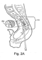
- Axial trans-sacral access to the lumbo-sacral spine as shown in Figure 2 eliminates the need for muscular dissection and other invasive steps associated with traditional spinal surgery while allowing for the design and deployment of new and improved instruments and therapeutic interventions, including stabilization, mobility preservation, and fixation devices/fusion systems across a progression-of-treatment in intervention. More specifically, clinical indications for the multi-level axial spinal stabilization systems and the motion management assemblies described herein include patients requiring interventions to treat pseudoarthrosis, revisions of previous interventions, spinal stenosis, spondylolisthesis (Grade 1 or 2), or degenerative disc disease as defined as back pain of discogenic origin with degeneration of the disc confirmed by history and radiographic studies.
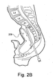
- Figure 2 provides an introductory overview of the process with Figure 2A and 2B showing the process of "walking" a blunt tip stylet 204 up the anterior face of the sacrum 116 to the desired position on the sacrum 116 while monitored on a fluoroscope (not shown). This process moves the rectum 208 out of the way so that a straight path is established for the subsequent steps.
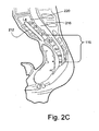
- Figure 2C illustrates a representative axial trans-sacral channel 212 established through the sacrum 116, the L5/sacrum intervertebral space, the L5 vertebra 216, the L4/L5 intervertebral space, and into the L4 vertebra 220.
- trans-sacral approach to provide spinal therapy is described in co-pending and commonly assigned United States Patent Application 10/309,416 .
- a brief overview of this method of accessing the spinal region to receive therapy is useful to provide context for the present invention.
- a pre-sacral approach through percutaneous anterior track towards sacral target, through which trans-sacral axial bore will be made and channel extended distally for subsequent advancement of multi-level axial spinal stabilization assemblies.
- An anterior, pre-sacral, percutaneous tract extends through the "pre-sacral space" anterior to the sacrum.
- the pre-sacral, percutaneous tract is preferably used to introduce instrumentation to access and prepare (e.g., by drilling a bore in the distal/cephalad direction through one or more lumbar vertebral bodies and intervening discs.
- Percutaneous in this context simply means through the skin and to the posterior or anterior target point, as in transcutaneous or transdermal, without implying any particular procedure from other medical arts.
- percutaneous is distinct from a surgical access, and the percutaneous opening in the skin is preferably minimized so that it is less than 4 cm across, preferably less than 2 cm, and, in certain applications, less than 1 cm across.
- the percutaneous pathway is generally axially aligned with the bore extending from the respective anterior or posterior target point through at least one sacral vertebral body and one or more lumbar vertebral body in the cephalad direction as visualized by radiographic or fluoroscopic equipment. More specifically, as shown in Figure 2b , the lumbar spine is accessed via a small skin puncture adjacent to the tip of the coccyx bone. The pre-sacral space is entered, using standard percutaneous technique, and the introducer assembly with the stylet's blunt tip serving as a dilator is placed through the paracoccygeal entry site.
- the blunt tip is rotated back against the anterior face of the sacrum and "walked” to the desired position on the sacrum under fluoroscopic guidance.
- the blunt-tipped stylet is removed and a guide pin, or wire, is safely introduced through the guide pin introducer tube, and "tapped in”.
- the guide pin establishes the trajectory for placement of subsequent bone dilators and sheath through which a twist drill is introduced creating an axial bore track, the lumen of which is extended distally.
- the guide pin maintains the axial alignment of access & preparation tools as well as the alignment of cannulated spinal stabilization devices and assemblies, of larger diameter than the bore track, that are subsequently introduced over a 23" long, 0.090" diameter guide pin and through an exchange cannula for deployment of within the vertebral column, as described at least in part in co-pending and commonly assigned United States Patent Application Nos.
- spinal arthrodesis meaning fixation/fusion, leading to immobilization of two vertebral bodies within a motion segment, relative to one another
- soft fusion refers to immobilization by means of the introduction of bone growth facilitation/augmentation materials (e.g., osteogenic; osteoconductive media) without accompanying implantation of fixation devices (e.g., fusion rods).
- spinal arthroplasty and/or motion management encompass dynamic stabilization options for treating disc degeneration in a progression-of-treatment, i.e., when is deemed too radical an intervention based on an assessment of the patient's age, degree of disc degeneration, and prognosis.
- dynamic refers to non-static motion management devices inherently configured to allow mobility by enabling or facilitating forces or load bearing that assist or substitute for physiological structures that are otherwise compromised, weakened or absent.
- Mobility devices providing dynamic stabilization are provided across a progression-of-treatment for treating symptomatic discogenic pain, ranging from treatment in patients where little degeneration or collapse is evident radiographically, to those for whom prosthetic nucleus devices or total disc replacements are indicated.
- a prosthetic nucleus would be indicated in patients with a greater degree of degeneration and loss of disc height but not to the stage where advanced annular break-down is present.
- a PN would go beyond DS by including an aggressive nucleectomy and subsequent filling of the de-nucleated space with an appropriate material.
- TDR total disc replacement
- therapeutic dynamic stabilization device assemblies which provide, by design, resistance and limitation of motion in a controlled manner.
- “resistance” refers to the force required to move through a full range of motion
- “limitation” refers to not force but degree, i.e., curtailment of full range of motion in one or more directions.
- full range of motion comprises about 12 degrees of flexion, about 8 degrees of extension, about 4 degrees of left or right lateral bend, and about 2 degrees of clockwise or counterclockwise motion at each motion segment.
- Biomechanical properties of the mobility devices may be altered by design. For example, a flex coupler embodiment which supports a static load of about 100 lbs.
- devices may be preferentially configured to comprise, for example, a mechanical stop(s) to limit motion, and/or resistance to motion, e.g., by varying cross-sectional area and hence stiffness, or other biomechanical properties relevant to preserving or restoring physiological function with respect to mobility.
- the assemblies may be constructed to provide full, unconstrained range of motion, semi-constrained range of motion where full range of motion is allowed in combination with increased resistance to motion, or limited range of motion wherein the extent of motion in one or more degrees of freedom is mechanically limited, with or without increased resistance to motion.
- the spinal devices comprised in the inventive assemblies preferably selectively approximate the biomechanical properties (e.g., substantially matched bulk and compression modulus) of the physiological vertebral or disc structure(s) depending on the particular function(s) for which specific therapeutic procedure(s) are indicated.
- an axial spinal MM device comprises PN augmentation or replacement material, that provides the same load-bearing functions and characteristics as the natural disc nucleus and of the natural disc, said PN material contained within expandable membranes, comprised of elastomeric materials, e.g., silicone.
- elastomeric materials e.g., silicone.
- Exemplary silicone is such as that obtained from Nusil Silicone Technology located in Carpeneria, California, exhibiting elongation of between about 500% and about 1500%, and most preferably at about 1000%, and having a wall thickness of 0.015" serve as a primary dynamic stabilization component, via load assimilation and load distribution, when filled and expanded via infusion or inflation with an appropriate material.
- the spinal MM device and may be configured via engagement means as part of an inter-axial device assembly comprising a plurality of axial MM devices, or an assemblies comprising some combination of axial MM device(s) and axial fixation rod(s).
- this is achieved by means of axial deployment of devices with an aspect ratio of greater than 1, i.e., the device dimension in the axial vertebral plane is greater than the device dimension in any orthogonal direction to that axial plane in close proximity to the physiological instantaneous center of axial rotation.
- axial rod refers to axially deployed spinal implants which are fabricated, for example, by machining from metal, cylindrical (i.e., rod-like) solid blanks, and said term may encompass fixation/fusion or motion management devices as indicated, since the specific nature, form and function of such devices are determined by/dependent upon final implant configuration.
- fixation/fusion or motion management devices as indicated, since the specific nature, form and function of such devices are determined by/dependent upon final implant configuration.
- the fabrication, forms, and function of various implant configurations of axial spinal motion management devices to preserve or restore mobility are disclosed in co-pending and commonly assigned U.S. Patent Application Nos., 10/972,184 ; 10/972,039 ; 10/972,040 , and 10/972,176 , all of which were filed on October 22, 2004.
- the axial rods serve multiple purposes, including but not limited to, modifying the height between the bodies, assuming physiological axial loads, providing access for the introduction of osteogenic and/or osteoconductive materials, and precluding device expulsion by means of anchoring.
- the method of using the distraction/fusion rod generally comprises the steps of: determining the desired change in disc height between targeted vertebral bodies; selecting a rod with the appropriate thread pitches in the distal and proximal sections to achieve the desired change in height; accessing the targeted bodies by creating an axial bore that extends in the distal (cephalad) direction from the a target point on the anterior surface of the sacrum to the disc space between the targeted bodies; extending the axial bore in the distal direction to create an extended portion of the axial bore, wherein the extended portion has a smaller diameter than the portion of the axial bore extending from the sacral target point to the disc space between the targeted bodies; and advancing and implanting the selected rod into the targeted bodies to achieve the desired change in disc height Moreover, when devices and assemblies are anchored
- a set can be male or female.
- a set of threads can be right-handed or left-handed.
- the number of threads per unit length (pitch) can be varied from one set of threads to another.
- the minor and major diameters of the threads can be varied from one set of threads to another.
- form of the threads - the shape of a cross section of a thread can vary from one set of threads to another (such as V-shaped threads or buttress threads).
- one set of threads is said to be the same type as another set of threads when all of these parameters are the same such that the another set of threads can be rotated into a thread path cut by the first set of threads without needing to cut a new thread path (if the another set of threads is keyed or timed to place the another set of threads into the proper position to start into the previously cut thread path).
- stop flow means such as an axial rod plug are used to preclude leakage or migration of the prosthetic nucleus material either through an axial spinal dynamic stabilization rod or from the intervertebral disc space.
- assembly may refer, in context, to a single implant which when fully deployed within the spine comprises at least two distinct parts that are configured and engaged in and referred to as an intra-axial alignment, for example, an axial rod and an axial rod plug internally engaged and axially aligned within (i.e., longitudinally) said axial rod.
- assembly may refer to the combination of a plurality of single-part implants and/or two part intra-axial devices-assemblies, such as just described above, which are configured with engagement means enabling constructs as inter-axial components that collectively comprise an integrated unit or assembly, for example, a distal component rod or rod-assembly as the distal implant in engagement along the center line of a longitudinal axis and axially aligned with a proximal component rod or rod-assembly, as the proximal implant wherein the two components collectively comprise a two-level axial stabilization assembly for two adjacent motion segments, e.g., L4-L5 (distal) and L5- sacrum (proximal).
- L4-L5 distal
- L5- sacrum proximal
- multi-level axial stabilization assemblies are configured from two components: a distal component rod, comprising a threaded distal end with a first thread pitch and a threaded proximal end with a second, different thread pitches (hereinafter referred to as dissimilar thread pitches); and a proximal component rod, comprising a distal end that is a tapered and non-threaded cylinder and a threaded proximal end comprising tapered distal threads; said component rods (with or without accompanying intra-axially engaged rod plugs) which are sequentially deployed by means of instrumentation and methods as will be described below, as fixation implants in adjacent motion segments, e.g., first in L4-L5 (superior/distal component rod) and then L5-sacrum (inferior/proximal component rod), respectively; so that the subsequent engagement of the distal end of the proximal component rod internally within and in inter-axial alignment with the proximal
- Thread pitch is defined as the distance between corresponding points on consecutive threads, i.e., threads per inch or TPI.
- This design using dissimilar thread pitches allows each end of the rod to screw into the superior and inferior vertebral bodies of the L4-L5 motion segment at independent rates resulting in distraction of the two vertebrae and an increase in disc height without the need for additional "distracting" instrumentation as is required in other arthrodeses.
- the degree or amount of distraction to be achieved may be selected by pre-determining the of variability in thread pitch between the threaded distal and proximal ends.
- the use of dissimilar thread pitches to distract vertebral bodies within a single motion segment is described in commonly assigned United States Patent 6,921,403 "Method and Apparatus for Spinal Distraction and Fusion" issued on July 26, 2005.
- the proximal component rod in order to enable adequate and simultaneous distraction and subsequent therapy of a second motion segment (proximal) disc space, need only be threaded at its proximal end as described in the preceding paragraph, so that as its threads engage the proximal vertebral body said component is both anchored and advanced into the proximal disc space until its distal end subsequently engages the distal component rod's proximal end, effectively comprising an integral implant assembly.
- distraction of the proximal disc space is thereafter achieved by means of force applied, in the distal direction, to the proximal end of the proximal component subsequent to said engagement of the two components, so that the distal end of the proximal component will push against and lift the proximal end of the distal component.
- the device assemblies are configured to mechanically and adjustably, distract multiple disc spaces and configured to be deployed so as to be oriented in approximately the line of principal compressive stress, i.e., the device is configured to be placed at approximately the center of rotation in a human disc motion segment. In turn, this yields a more uniform, radial distribution of loads to more closely approximate physiological load sharing.
- the axial stabilization devices disclosed herein are less likely to cause the phenomena of subsidence and transition syndrome.
- subsidence refers to the detrimental descent of an orthopedic implant into bone that surrounds it.
- Transition syndrome refers to altered biomechanics and kinematics of contiguous vertebral levels and concomitant risk of adjacent motion segment instability that may occur as a result of spinal therapeutic procedures that are suboptimal in terms of their ability to restore physiological function and properties, and thus risk a cascading deleterious effect on surrounding otherwise healthy tissue.
- an axial spinal stabilization system in particular, for the anterior lumbar spine.
- yet another advantage of the present invention is the concurrent implementation of a combination of therapies , i.e., deployment of spinal assemblies are disclosed that enable dynamic stabilization via implantation of one or more prosthetic nucleus devices or other mobility preservation/restoration devices, such as those disclosed and described previously in co-pending and commonly assigned U.S. Patent Application Nos. 10/972,184 ; 10/972,039 ; 10/972,040 , and 10/972,176 , all of which were filed on October 22, 2004, as alternative options to or together with fixation rods facilitating fusion of the vertebral bodies, to selectively achieve motion management rather than elimination of motion with respect to a targeted plurality of motion segments within multiple spinal levels.
- MM devices decompress the disc and alleviate pain caused by nerve impingement, usually posterior, by means of either inducing slight segmental kyphosis (introduction of added convex curvature through increasing the height on the posterior side of the disc more than on the anterior side of the disc) or straight elevation, and by creating limits and resistance to segmental motion.
- devices are able to provide both stable anterior and posterior load support (e.g., loads that may approximate 10 times the body weight of a patient) and adequate medial-lateral and rotational support, without adjunctive posterior instrumentation and without accompanying osteogenesis.
- Certain of the dynamic stabilization devices of the present invention comprise a flexible member in between more rigid distal and proximal threaded anchor portions.
- the flexible member which may comprise a cable, spring, flexible coupler, stacked-washers, inflatable bladder (e.g., expandable membrane), or a combination thereof, serves as a "shock absorber", and is able to assimilate forces or redistribute loads.
- the mobility device assembly comprising one or more flexible member (s), in combination with at least one anchor portion(s), may be configured from among these design concepts and embodiments, including: helical flexure (flexible coupler) designs, comprising one-piece or two-piece devices that may be configured with or without an integral, elastomeric or elastic inflatable, i.e., expandable, membrane that serves to maximize surface area over which loads are distributed, and that may or may not assist in distraction; cable designs, comprising one piece of fixed length, with or without an inflatable membrane, or two or more parts of variable length; ball and track multi-part designs; "stacked washer” designs, and anchored nuclear replacements.
- helical flexure (flexible coupler) designs comprising one-piece or two-piece devices that may be configured with or without an integral, elastomeric or elastic inflatable, i.e., expandable, membrane that serves to maximize surface area over which loads are distributed, and that may or may not assist in distraction
- cable designs comprising one piece of fixed length, with or without an inflatable
- PND axially deployed in the L5- sacrum lumbar spine enable/accommodate range of motion of between about 10° to 15° flexion; between about 7° to about 10° extension; about 5° of left or right lateral bending and between about 1 ° to about 2° clockwise or counterclockwise axial rotation
- those implanted in L4-L5 enable/accommodate range of motion of between about 8° to 10° flexion; between about 5° to about 7° extension; between about 5° to about 7° left or right lateral bending; and between about 1° to about 4° clockwise or counterclockwise axial rotation.
- the overall length of, for example of the proximal component (L5-Sacrum) of the MM device-assembly ranges from about 40 mm (size small) to about 60mm (size large), and the expandable membrane component may be folded within a cannulated section of the mobility device during device delivery to the target site, and then deployed, e.g., unfolded, in situ via expansion by infusion or inflation into the (denucleated) intervertebral disc space of the L5-Sacrum motion segment.
- preferential vertebral body positioning, distraction and decompression, and static or dynamic stabilization are achieved by interventions which at the same time mitigate surgical risks associated with traditional, conventional procedures, e.g., bleeding, neurological damage, damage to soft tissue, spinal cord impingement or damage and infection, and, additionally, provide an improved level of clinical biomechanical performance compared with conventional spinal components and techniques for spinal arthrodesis or arthroplasties on multiple levels within the spinal column.
- another advantage of the inventive spinal axial stabilization system is that deployment and orientation present no exposed surfaces for impingement of nerves, vessels, or soft tissue. Additionally, due to the axial delivery of the implant via a protected channel, there is no retraction of muscles and no exposure to major vessels or soft tissue as with the delivery system for systems delivered from other surgical approaches.
- references to anterior approaches, while preferred, are for convenience only, and that both pre-sacral anterior and posterior approaches and subsequent trans-sacral axial stabilization methods and devices afford significant advantages over current practice, including: the patient is in a prone position that is easily adaptable to other posterior instrumentation; blood loss is minima; soft tissue structures, e.g., veins, arteries, nerves are preserved, and substantially less surgical & anesthesia time is required compared with conventional procedures; the implants of the present invention are intended to preserve or restore function, not merely alleviate pain.
- US 4,858,601 is directed at an adjustable compression bone screw that has a shaft having first and second sections each with an external screw thread that may be rotated as a unit or independently.
- the screw includes means adapted to receive a first driving tool for driving the shaft as unit and is further adapted to receive a second driving tool for rotating the second section independently of the first section.
- US 2003/0158557 A1 discloses an implantable spinal distraction/fusion rod with varied thread pitch and diameters along different positions of its length that is capable of distracting two or more vertebral bodies relative to each other and/or facilitating the procedure of fusing the vertebral bodies together from within the spine. Further, four methods of using the rod to distract and/or fuse two or more vertebral bodies from within the spine are disclosed.
- MM fusion and mobility maintenance
- inventive concepts are illustrated in a series of examples, some examples showing more than one inventive concept. Individual inventive concepts can be implemented without implementing all details provided in a particular example. It is not necessary to provide examples of every possible combination of the inventive concepts provide below as one of skill in the art will recognize that inventive concepts illustrated in various examples can be combined together in order to address a specific application.
- Figure 1 is a side view of a human spine
- Figures 2A , 2B , and 2C show a trans-sacral approach and the formation of a channel for receipt of therapeutic devices
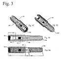
- Figure 3 shows one embodiment of a distal distraction rod
- Figure 4 shows an installed assembly with a distal distraction rod and a proximal distraction rod
- Figure 5 shows one embodiment of a proximal distraction rod
- Figure 6A shows an assembly of a distal distraction rod and a proximal distraction rod along with optional plugs
- Figure 6B shows a quarter-round cut-away perspective drawing of an assembly with a thrust bearing 680
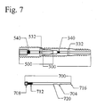
- Figure 7 shows another plug that joins the distal and proximal rods
- Figure 8 shows yet another plug embodiment that uses a separate plug within the proximal rod that does not connect the proximal rod to the distal rod;
- Figure 9 presents a flow chart for the process of imposing two distractions on adjacent intervertebral spaces
- Figure 10 illustrates the use of the present invention for a situation calling for the consecutive therapy of three adjacent motion segments
- Figure 11 shows a two-level therapy provided by the sequential installation of two axially implantable rods
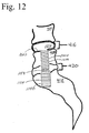
- Figure 12 shows a two-level therapy provided by the sequential installation of two axially implantable rods but does so without anchoring to the vertebral body beyond the most cephalad intervertebral disc space to receive the therapy;
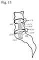
- Figure 13 shows the use of the present invention to provide dynamic stabilization to two adjacent motion segments
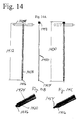
- Figure 14 shows a preferred driver for insertion or removal of plugs as this driver has a retention rod to engaging the plug to the distal tip of the driver.
- Figure 3 shows one embodiment of an exemplary distal distraction rod 300 in accordance with the present invention.
- Figure 3A shows the exterior
- Figure 3B provides a cross section
- Figures 3C and 3D provide solid surface view in perspective with a longitudinal section removed to expose the interior bore 304.
- the operation of the distal distraction rod is best explained in connection with spinal components as shown in Figure 4.
- Figure 4 shows three adjacent vertebral bodies called here distal vertebral body 404, medial vertebral body 408, and proximal vertebral body 412.
- the three vertebral bodies define two adjacent motion segments, comprising intervertebral disc spaces, the distal intervertebral disc space 416 and the proximal intervertebral disc space 420.
- the proximal vertebral body is drawn without a complete outline as the three vertebral bodies are not meant to be limited to specific vertebral bodies.
- the proximal vertebral body 412 is not necessarily the sacrum 116 in Figure 2C as the axial trans-sacral channel 212 may have been extended sufficiently into the spine so that the most distal vertebral body 404 is L3 or higher.
- the distal distraction rod 300 is comprised of a distal threaded section 308, a proximal threaded section 312 and in this preferred embodiment, a waist section 316.
- the use of dissimilar thread pitches allows for the controlled distraction of two vertebral bodies ( Figure 4 elements 404 and 408) when the distal threaded section 308 is engaged with a distal vertebral body 404 and the proximal threaded section 312 is engaged with the medial vertebral body 408.
- dissimilar thread pitches to distract vertebral bodies within a single motion segment is described in co-pending and commonly assigned United States Patent Application Serial No. 10/309,416 filed on December 3, 2002 , now US Patent No. 6,921,403 .
- the use of dissimilar thread pitches can be used in the distal axial rod 300 which is advanced into the vertebral bodies (404 and 408) by rotating the trailing end of the distal axial rod in the same direction as the "handedness of the screw".
- the thread on the proximal threaded section 312 and the thread on the distal threaded section 308 both extend counterclockwise (or both clockwise) around the elongate body comprising the device, and preferably the distal and proximal threads are self-tapping.
- a distal axial rod 300 having a thread pitch in its threaded distal section 308 that is finer relative to the thread pitch in the threaded proximal section 312 causes distraction of the intervertebral disc space 416 between the two engaged vertebral bodies 404 and 408 as each turn of the distal axial rod 300 in the proper direction with respect to handedness of the threads will move the distal axial rod 300 relative to the distal vertebral body 404 a first amount but the distal axial rod 300 will move relative to the more proximal vertebral body 408 a larger amount.
- the ratio of the first amount to the larger amount will be proportional to the ratio of the pitch of the distal threaded section to the pitch of the proximal threaded section.
- One of skill in the art can appreciate that in order to effect a more significant distraction, one would select more significantly dissimilar thread pitches than the combination shown in Figure 3 . As rotation in one direction causes distraction, rotation in the opposite direction causes compression.
- distal axial rod 300 include a chip breaker section 320 to facilitate screwing the distal end of the distal distraction rod into the distal vertebral body.
- the leading edge 324 of the thread for the proximal threaded section grows from the minor diameter to the major diameter of the threaded section.
- the bore 304 of the distal distraction rod 300 includes several apertures 332 that extend radially outward at the waist 316. These apertures can be used to deliver material as part of providing therapy to the motion segment, including bone paste or other materials to promote fusion.
- the distal end 328 of cavity 304 is not generally used as an aperture for delivery of therapeutic material as this distal end 328 would be positioned in a vertebral body rather than in an intervertebral space. The opening at the distal end 328 is useful when deploying the distal distraction rod over a guide wire.
- the channel prepared for the insertion of the distal distraction device can be of a smaller cross section as the channel enters then distal vertebral body than the cross section of the channel through the medial vertebral body such that the distal section of the distal distraction device can pass through the medial vertebral body without having to be screwed through. While this may appear attractive to pass the distal threaded section through the medial vertebral body in that the bone around the channel is not marred or otherwise weakened, this is not a preferred practice.
- a preferred practice is to use a sequence of decreasing major diameters, but not necessarily to the extent that the more distal thread sets can be passed through without rotating the rod.
- Rod driver engaging zone 336 can be made in one of several configurations known to those of skill in the art to allow a driver to impart rotation to the rod.
- the proximal end of the distal distraction rod 300 can be fitted with a female hex head suitable for driving with a driver having a corresponding male hex head.
- a suitable driver is described in priority document No. 60/601,842 filed August 14, 2004 for Method & Apparatus for Multi-Level Stabilization of the Spine.
- the distal distraction rod 300 may be configured to have a set of female extraction threads 348 (for example left-handed metric thread pattern M7) within the proximal end of the bore 304.
- the thread matches the thread on an extraction driver tool.
- the process to extract a previously inserted rod would start with using the driver to rotate the rod in the counterclockwise direction to start the extraction of the previously inserted rod. (In some cases the extraction could be performed without the initial involvement of the driver to start the disengagement.)
- the extraction tool can be used to engage the female extraction threads 348 and pull the distraction rod out the rest of the way, if there is a need for such extraction, e.g., in the event of revision or implant selection resizing.
- left-handed threads is preferred as this allows the extraction of the engaged right-handed threads of the rod to be disengaged by rotating the extraction tool in the normal counterclockwise direction.
- counterclockwise rotation will cause the left-handed threaded section of the distal tip of the extraction tool to engage with corresponding threads on the rod to be extracted.
- further rotation of the extraction tool in the counterclockwise direction will disengage the right-handed threads on the rod from the vertebral body. Once the rod is disengaged from the vertebral body, it can be pulled out with the tip of the extraction tool as it will be engaged with the left-handed threads of that tool.
- the left-handed threads are cut into the polygonal walls of the rod driver engagement zone. (Perhaps best seen in Figure 6B described below).
- the use of extraction tools with left-handed threads to remove a rod is not limited to distal distraction rods, but can be used for any installed device that is engaged with right-handed threads including plugs (described below).
- an extraction tool would have right-handed threads so that clockwise rotation of the extraction tool would disengage such a device.
- Figure 5 shows an exemplary proximal distraction rod 500 for use with the present invention. More specifically, Figure 5A shows the exterior of the proximal distraction rod 500; Figure 5B shows a cross section along the length of the proximal distraction rod 500; and Figure 5C provides a solid surface perspective view of the proximal distraction rod 500 with a longitudinal segment removed.
- Proximal distraction rod 500 is comprised of a threaded section 504 and an engagement section 508. While not shown in this embodiment, one of skill in the art could reduce the length of the threaded section so that the threaded section ends before the beginning of the engagement section, e.g., by including a waist as seen in the exemplary distal distraction rod 300.
- the threaded section 504 has a tapered section 512 and a straight section of thread 516 as this configuration facilitates threading the leading edge of the threaded section into the proximal vertebral body 412.
- the engagement section is not threaded but has a tapered leading edge 520. As the proximal distraction rod 500 is advanced in the channel, the tapered leading edge 520 of the engagement section 508 engages with the proximal end of the distal distraction rod 300. The engagement section 508 proceeds into the distal distraction rod bore 304 until the shoulder 524 of the proximal distraction rod presses against the trailing edge of the distal distraction rod 300.
- the distal engagement section 508 of the proximal distraction rod essentially fills the corresponding portion 346 ("engagement zone") of the bore in the distal distraction rod 300.
- the specification for the bore size for the portion to receive the cylindrical shank is 0.635 cm (0.250 inches) (+ 0.005 inches, - 0.000 inches) and the specification for the dimension of the cylindrical shank is 0.634 m (0.2495 inches) (+0.000 inches, + 0.005 inches).
- the angle used for the tapered leading edge 520 portion of the distal engagement section 508 is repeated in the corresponding section of the bore 304.
- This close fit of the leading portion of the proximal distraction rod 500 with the trailing portion of the bore 304 in the distal distraction rod serves to maintain the axial alignment of the two rods to one another while retaining the ability for the proximal distraction rod 500 to rotate relative to the distal distraction rod 300 without imparting a rotation to the distal distraction rod and thus altering the previously imposed distal distraction.
- the amount of distraction imposed on the proximal intervertebral disc space 420 is independent of the amount of distraction imposed on the distal intervertebral disc space 416.
- the pitch of the thread on the threaded portion 504 of the proximal distraction rod is not relevant to the amount of distraction that can be imposed (beyond changing the amount of distraction per turn of the distraction rod).
- the handedness of the thread for the threaded portion 504 of the proximal distraction rod can be chosen independent of the handedness of the thread used for the proximal distraction rod so that distraction is imparted by rotating the distal distraction rod in a first direction and distraction is imposed by rotating the proximal distraction rod in the opposite direction.
- the cross section of the proximal distraction rod 500 can be selected to be sufficiently larger than the major diameter of the proximal threaded section 312 of distal distraction rod 300 to allow the cross section of the channel formed in proximal vertebral body 412 to be sized so that the distal distraction rod 300 can be passed through the proximal vertebral body 412 without being screwed through it or otherwise marring the bone surface exposed by the channel.
- Proximal distraction rod 500 has a set of apertures 532 connected to the bore 528 of the proximal distraction rod 500. These apertures can be used to distribute therapeutic material as part of the procedure of motion segment fusion. In a preferred embodiment, there are four apertures spaced 90 degrees apart.
- Rod driver engaging section 536 can be made in one of several configurations known to those of skill in the art to allow a driver to impart rotation to the rod.
- the proximal end of the proximal distraction rod 500 can be fitted with a female hex head suitable for driving with a driver having a corresponding male hex head.
- a suitable driver is described in priority document No. 60/601,842 filed August 14, 2004 for Method & Apparatus for Multi-Level Stabilization of the Spine.
- a set of female extraction threads 548 (preferably left-handed metric threads) at the proximal end of the bore of the proximal distraction rod 500 can be used for the extraction of the proximal distraction rod as discussed in connection with female extraction threads 348.
- Female threaded section 540 for use in securing a bore plug in the bore 528 as will be discussed in greater detail below.
- the purpose of the axial rod plug is to preclude leakage or migration of the osteogenic, osteoconductive, or osteoinductive gel or paste which is inserted by means of an augmentation media (e.g., bone paste; PN material) inserter through apertures from the cavity of the distal or proximate distraction rods into the intervertebral spaces as part of the process of promoting fusion or for other therapeutic purposes.
- an augmentation media e.g., bone paste; PN material
- the material inserted in this way is intended to fill available volume not occupied, e.g., by previously introduced autologous bone graft material, in its entirety.
- the plug is fabricated from the same titanium alloy as the axial rod, although it may be formed from other suitable (e.g., biocompatible; polymeric) materials.
- Figure 6A presents a representation of a distal distraction rod 300 with a proximal distraction rod 300 shown inserted into the proximal end of the cavity of the distal distraction rod.
- the cavity 304 of the distal distraction rod is connected to apertures 332 and it may be desirable to plug the cavity 304 to prevent or limit the ingress of material into the cavity 304 including the post-treatment ingress of therapeutic material delivered by through these apertures.
- a distal rod plug 604 is shown (not to scale) with a male threaded section 608 that corresponds to female threaded section 340.
- the distal rod plug 604 can be driven by a hex driver that is appropriately sized to drive a female hex fitting 612 in the trailing edge of the cavity in the distal rod plug 604.
- a suitable driver is described in priority document No. 60/601,842 filed August 14, 2004 for Method & Apparatus for Multi-Level Stabilization of the Spine.
- the distal rod plug 604 when installed in the distal distraction rod 300 is seated distal to the tapered section 344 of the cavity so that the installed distal rod plug does not interfere with the insertion of the proximal distraction rod 500 into the proximal end of the distal distraction rod 300.
- the cavity in the distal rod plug 604 has a female threaded section 616 which will be described in connection with the proximal distraction rod plug 650.
- Proximal rod plug 650 has male threaded section 654 which is adapted to engage female threaded section 616 of distal rod plug 604 to bind together the assembly including distal distraction rod 300 with distal rod plug 604 along with proximal distraction rod 500 to provide one rigid assembly.
- the proximal rod plug 650 does not engage via male threads with female threaded section 540 in the proximal end of the cavity of the proximal distraction rod 500.
- Proximal rod plug 650 in turn has an axial cavity with a female threaded section 658. This threaded cavity is used in connection with a preferred plug driver described below that uses a retention rod to engage with the plug so that it remains engaged with the distal tip of the driver until the driver is disengaged from it.
- the proximal rod plug 650 can be driven by a hex driver that is appropriately sized to drive a female hex fitting 662 in the trailing edge of the cavity in the proximal rod plug 650.
- a suitable driver is described in priority document No. 60/601,842 filed August 14, 2004 for Method & Apparatus for Multi-Level Stabilization of the Spine.
- Figure 6B shows a perspective view with a quarter section removed of an assembled combination of a proximal rod 300, a distal rod 500, a distal rod plug 604 and a proximal rod plug 650 that engages with the proximal end of the distal rod plug 604.
- the components have been sized to allow for the use of a thrust bearing 680 which serves to facilitate (e.g., lubricate) the rotation of the proximal rod 500 against the distal rod 300 so that the proximal rod can advance and rotate without imparting rotation to the previously installed distal rod 300.
- the thrust bearing can be as shown here a washer shaped structure. As the thrust bearing will be placed inside a human body, it should be made of a biocompatible material and tolerant of the forces it may see in use. As the thrust bearing is meant to facilitate the rotation of the more proximal rod 500 relative to the more distal rod 300 while under an axial load, the coefficient of sliding friction between the thrust bearing and the rod moving relative to the thrust bearing should be less than the coefficient of sliding friction between two rods as shown in Figure 6A .
- UHMWPE ultra high molecular weight polyethylene
- PEEK polyether ether ketone
- the perspective shown in Figure 6B includes the female extraction threads 348 for the distal distraction rod 300 and a better view of the female extraction threads 548 for the proximal distraction rod 500. Note in the preferred embodiment the female extraction threads such as 548 are cut into the most proximal section of a polygonal rod driver engaging section 536.
- Plug 700 has a male threaded section 704 that is adapted to engage with female threaded section 340 when an appropriate driver (not shown in Figure 7 ) presses upon and rotates the plug through interaction at female socket 708.
- the cavity of plug 700 has female threaded section 712. When fully inserted, the tip 716 of plug 700 is beyond the apertures 332 so as to block the ingress of material back through those apertures or through apertures 532 of the proximal distraction rod.
- the pair of plugs 604 and 650 may be preferable to plug 700 as the insertion of distal rod plug 604 seals off the apertures 332 before the proximal distraction.
- Figure 8 illustrates a third embodiment in which the ingress of material into the proximal distraction rod 500 is limited by the use of a plug 804 that is engaged with the proximal distraction rod 300 rather than the distal distraction rod 500 or a plug within distal distraction rod 500. More specifically, Figure 8A shows a partial cross section and Figure 8B shows a side-elevational perspective view of a proximal distraction rod 300 inserted into the proximal end of a distal distraction rod 500. The distal distraction rod 500 is sealed internally with a plug 804 and a proximal rod plug 850 is located in the proximal distraction rod 300.
- a male threaded section 808 and 858 engage corresponding female threaded sections 340 and 540 (best seen in Figure 6 ) to secure the plug (804 or 850) into the cavity of the distraction rod.
- the plugs are driven by appropriate drivers that engage the engagement sections 812 and 862 (preferably female hex fittings).
- the tips 816 and 866 of the plugs are placed so that material cannot travel from the apertures back into the longitudinal cavities of the distraction rods.
- Figure 9 presents a flow chart for the process of imposing two distractions on adjacent intervertebral spaces.
- Step 905 calls for preparation of the channel to allow for the insertion of the axial distraction rods.
- Step 910 calls for engaging the threads from the distal threaded section 308 with the distal vertebral body 404 and the proximal threaded section 312 with the medial vertebral body 408.
- Step 915 calls for rotating the engaged distal distraction rod 300 by applying force to the rod drive engaging zone 336 to selectively impose a specific amount of distraction to the distal intervertebral space through the action of the differences in thread pitch between the distal threaded section 308 and the proximal threaded section 312. Note that the direction of rotation to impose a distraction is a function of the handedness of the threads and whether the finer pitch thread is on the proximal or distal set of threads.
- Step 920 calls for applying the desired therapy to the distracted distal intervertebral space 416.
- This therapy may include providing materials to the distal intervertebral space 416 through the apertures 332.
- Step 925 calls for the optional addition of a distal distraction rod plug such as distal distraction plug 604. This is optional as some medical providers may opt to not seal the cavity at all and some may rely on a plug applied after the proximal distraction that will seal both axial distraction rod cavities.
- Step 930 calls for threading the proximal distraction rod 500 into the proximal vertebral body 412.
- Step 935 calls for rotating the proximal distraction rod 500 until it pushes against the engaged distal distraction rod to impose a specific amount of distraction upon the proximal intervertebral disc space 420.
- the distal end of the proximal distraction rod 500 engages with the proximal end of the cavity in the distal distraction rod 300 so that the application of force by the proximal distraction rod 500 against the distal distraction rod 300 occurs without disturbing the axial alignment of the two distraction rods.
- the amount of distraction imposed on the proximal intervertebral disc space is not dependent on the amount of distraction imposed on the distal intervertebral space.
- Step 940 calls for the application of the therapy to the proximal intervertebral disc space 420 which may include the insertion of material into the proximal intervertebral space through the apertures 532.
- Steps 945, 950, and 955 provide for alternatives that can be selected to insert three different types of plugs into the proximal distraction rod.
- Step 945 calls for the addition of a proximal distraction rod plug such as shown in Figure 8 as element 850.
- a proximal distraction rod plug such as shown in Figure 8 as element 850.
- Such a plug seals the cavity of the proximal distraction rod but does not serve to join the proximal distraction rod 500 with the distal distraction rod 300 (either directly or indirectly through a distal plug).
- Step 950 calls for the insertion and engagement of a proximal distraction plug with the distal distraction rod 300. This was illustrated by element 700 in Figure 7 which engages with the female threaded section 340 in the distal distraction rod 300.
- Step 955 calls for the insertion and engagement of a proximal distraction plug with the distal distraction rod plug such as is shown in Figure 6 as proximal distraction rod plug 650 engages with previously inserted distal distraction rod plug 604 to provide added stability by joining the proximal distraction rod 500 to the distal distraction rod 300.
- an inter-rod connector provides a function of connecting the two rods together whether or not sealing is desired or even provided by the inter-rod connector.
- a connector between two axial distraction rods in keeping with the teachings of the present application are intended to be within the scope of the claims whether or not such a connector serves a purpose of acting as a "plug" to limit the ingress of material into the cavity through a aperture as some distraction rods may not have apertures and some therapies may not call for the insertion of therapeutic material through the apertures.
- Figure 10 illustrates the use of the present invention for a situation calling for the consecutive therapy of three adjacent motion segments
- the three rod assembly is shown in outline but include indications of aspects of the interior cavities including threads, engaging sections for rod drivers and the engagement zones and engagement sections such as engagement zone 346 of the distal distraction rod 300 and the corresponding engagement section 1058 of the next distraction rod (described below).
- the four vertebral bodies illustrated in Figure 10 are the distal vertebral body 404 (L3), distal-medial vertebral body 1004 (L4), proximal-medial vertebral body 1008 (L5), and proximal vertebral body 412 (sacrum).
- the three intervertebral disc spaces between the four vertebral bodies are the distal intervertebral disc space 416, the medial intervertebral disc space 1012, and the proximal intervertebral disc space 420.
- This embodiment has three axial distraction rods, the distal distraction rod 300, a medial distraction rod 1050, and a proximal distraction rod 550.
- distal distraction rod 300 to distract the distal intervertebral disc space 416 through the use of two sets of threads of different pitches operates as described above.
- the lengths of the distal threaded section 308, proximal threaded section 312, and waist 316 will be adjusted to be appropriate for whatever motion segment is targeted whether it is L3/L4 instead of L4/L5.
- the threaded section 1054 of the medial distraction rod 1050 engages the proximal-medial vertebral body 1008
- continued rotation applied through an engagement between a driver and a corresponding rod driver engagement zone in the proximal cavity of the medial distraction rod causes the medial distraction rod 1050 to advance and push against the proximal end of the distal distraction rod 300.
- This advancement and pushing causes an enlargement of the intervertebral space, in this case the medial intervertebral disc space 1012.
- the apertures 1062 are positioned in the intervertebral space so that therapeutic material can be delivered to this space.
- the distal end of the medial distraction rod 1050 will have an engagement section 1058 that fit with close tolerances within the engagement zone 346 proximal end of cavity 304 within the distal distraction rod 300.
- the medial distraction rod 1050 is characterized by having an engagement section 1058 to engage with a correspondingly shaped portion of a cavity of a more distal rod and an engagement zone 1066 in a portion of the cavity at the proximal end of the medial distraction rod 1050 that is adapted for receiving the engagement section 566 of a more proximal distraction rod.
- the medial distraction rod 1050 is adapted to push against a more distal distraction rod and to be pushed by a more proximal distraction rod.
- the medial distraction rod 1050 would also include a rod driver engagement zone in the proximal end of the cavity for use by a corresponding driver and may include female threads 1072 for use by an extraction tool.
- a proximal rod 550 is subsequently threaded into the proximal vertebral body 412.
- the proximal rod 550 in this embodiment has apertures 562 in fluid communication with the internal cavity of the proximal distraction rod 550.
- the proximal distraction rod 550 would also include a rod driver engagement zone in the proximal end of the cavity for use by a corresponding driver and may include female threads 572 for use by an extraction tool.
- Figure 11 shows a two-level therapy provided by the sequential installation of two axially implantable rods.
- Distal rod 1104 is comprised of a distal threaded section 1108, a therapeutic section 1112, and a proximal threaded section 1116.
- the distal threaded section 1108 and the proximal threaded section 1116 have the same thread pitch in this example and thus the insertion of the distal rod 1104 would not impose a distraction on the distal intervertebral disc space 416 as the distal rod 1104 engaged with distal vertebral body 404 and medial vertebral body 408.
- Therapeutic section 1112 is shown here in outline after material has been inserted into the intervertebral space and retained by device membrane 1120.
- device membrane 1120 In order to make device membrane 1120 distinguishable in this drawing from the components in the motion segment, a small space has been left in the drawing between the device membrane and the other components in the motion segment. This is for purpose of illustration only as the expanded device membrane 1120 would conform to the shape of the intervertebral space. Subsequent illustrations showing analogous device membranes will likewise exaggerate the spacing between the device membrane and other components for the same reason.
- the proximal rod 1150 shown in Figure 11 has a threaded section 1154 and apertures 1158.
- the engagement between the distal and proximal rods is not visible in this drawing but can be done in the same manner as described above in connection with Figure 4 .
- Figure 11 does illustrate the point that the handedness of the threaded section 1154 does not need to be the same as the handedness of the threads used in the distal rod 1104 in order to achieve a distraction as the more proximal rod will push in the cephalad direction on the implanted more distal rod to increase the axial distance between the vertebral body engaged with the more proximal rod and the vertebral body or bodies engaged with the more distal rod.
- Figure 12 has a distal rod 1204 that has only one threaded section 1208.
- the distal rod is engaged with the medial vertebral body 408 but not with the distal vertebral body 404.
- a therapeutic section 1212 of the distal rod 1204 extends into the distal intervertebral disc space 416.
- the device After insertion of material into expandable device membrane 1220, the device expands to a conforming fit within the intervertebral disc space 416. While this distal rod 1204 did not impose a distraction through the use of two threaded sections of dissimilar thread pitch, one of skill in the art will recognize that some distraction could be imposed hydraulically by expanding a membrane within intervertebral disc space 416.
- Proximal rod 1150 of Figure 12 can be configured internally and operate as described in connection with Figure 11 .
- Figure 13 illustrates yet another use of the present invention to provide therapy to two adjacent spinal motion segments. More specifically, Figure 13 shows a distal rod 1204 with the various elements described in connection with Figure 12 . Figure 13 differs from Figure 12 in that the proximal rod 1350 is not used to fuse the motion segment of proximal body 412, medial body 408, and proximal intervertebral disc space 420 as was done in Figures 11 and 12 . Instead Figure 13 shows two adjacent motion segments receiving motion management therapy to provide for post-operative mobility in both of the treated motion segments.
- Proximal rod 1350 would be advanced axially towards distal rod 1204 by engaging the threaded section 1354 with the proximal vertebral body 412 through use of an appropriate rod driver and a rod driver engagement section in the proximal end of a longitudinal cavity in proximal rod 1350. After proximal rod 1350 engages with distal rod 1204 any subsequent rotation of proximal rod 1350 to advance the rod in the cephalad axial direction would cause the proximal rod 1204 and the engaged medial vertebral body 408 to move axially away from proximal vertebral body 412.
- material could be provided into the proximal end of the cavity in proximal rod 1350 and out apertures in the therapeutic section 1362 of proximal rod 1350 to expand device membrane 1370.
- motion management therapies that used membranes to contain the prosthetic nucleus material inserted into the intervertebral spaces through apertures in the rods
- the invention is not limited to these particular types of motion management devices.
- Other motion management therapies as described in the various co-pending applications or issued patents and their priority documents can be coupled with the teachings of the present invention to provide therapy to two or more adjacent spinal motion segments.
- motion management therapies that inject prosthetic nucleus material into the intervertebral space without a membrane are specifically included in the intended range of uses for the present invention.
- Table A is provided to highlight the various non-exhaustive examples of the range of applications of the teachings of the present invention.
- the table references the examples in this application and also the greater variety of examples in Provisional Application No. 60/601,842 filed August 14, 2004 for Method & Apparatus for Multi-Level Stabilization of the Spine.
- the various drawings referenced in the table and the text associated with those drawings in the provisional are incorporated here by reference.
- anchor refers to a threaded portion of a device or rod that engages a vertebral body;
- PN refers to prosthetic nucleus.
- Figure 14 shows a preferred driver for insertion or removal of plugs of the various types discussed above.
- Figure 14A shows the driver assembly 1400.
- the driver assembly 1400 has handle 1404 that is adapted for providing rotation to the driver assembly 1400 and consequently to the driven plug.
- the handle 1404 is connected to a driver shaft 1408 to form a driver 1412 with polygonal driver head 1416 as shown in Figure 14B .
- the driver head 1416 is part of a removable tip 1420 that is attached to the driver shaft 1416, such as by connection pin 1424.
- Retention rod 1450 is comprised of a threaded distal end 1454 and a rotation actuator 1458, in this case a knob.
- the retention rod 1450 can be inserted into the driver shaft 1408 and the threaded distal end 1454 extended through the driver shaft 1408 and out through the driver head 1416 as the retention rod 1450 is longer than the driver 1412.
- Figure 14C shows an enlarged detail of the driver head 1416 with the protruding threaded distal end 1454.
- the advantage of the driver with retention rod 1450 is that a plug can be engaged to the driver 1400 by engaging the threaded distal end 1454 with a corresponding portion of the proximal end of the plug. This can be done by holding the proximal end of the plug adjacent to the threaded distal end 1454 and rotating the rotation actuator 1458 to cause the threaded distal end to rotate relative to the driver shaft 1408 and the held plug.
- the distal end of the driver assembly 1400 can be inserted into the channel along with the engaged plug. After the distal end of the plug is inserted into the relevant device, the handle can be rotated to engage threads on the plug with threads in the device to engage the plug.
- the rotation actuator 1458 can be rotated to cause the threaded distal end 1454 of the retention rod 1450 to rotate relative to the driver head 1416 and the plug. Rotation in the proper direction (based on the handedness of the threads used on the threaded distal end 1454) will disengage the threaded distal end 1454 from the plug.
- the distal end of the driver assembly 1400 can be withdrawn from the channel.
- Extraction of a plug from a device would start with putting the threaded distal end 1454 of a retention rod 1450 (which is part of a driver assembly 1400) into the channel and adjacent to the proximal end of the plug to be extracted. Rotation of the rotation actuator in the appropriate direction for the threads used will cause the threaded distal end 1454 to engage with the installed plug. After the threaded distal end 1454 is engaged with the plug and the plug is engaged with the driver head 1416 then rotation of the driver assembly 1400 through the use of the handle 1404 will cause the plug to disengage from the device. After the plug is disengaged, it can be removed with the driver assembly as the driver assembly is removed from the channel because the plug is threadedly engaged with the retention rod 1450.
- the preferred embodiment discussed in detail above uses a set of axial distraction rods so that the cross section of the threaded sections of the rods gets progressively smaller.
- An alternative is that two consecutive sets of threads on two different distraction rods can have the same thread and cross section. For example, if the proximal threaded section 312 of the distal distraction rod 300 and the threaded section 504 of the proximal distraction rod 500 have the same thread pattern, then keying can be useful to prevent cross threading.
- an exchange cannula with a threaded inner diameter that docks with /attaches to the sacrum may be utilized to avoid cross-threading.
- Each rod can then be readily threaded through the cannula to initially engage the vertebral body at the same location. While this method can be used with an effort to perform two distractions of adjacent intervertebral spaces, it is particularly useful when performing distractions of three or more adjacent intervertebral spaces as keying eliminates the need for four progressively larger cross sections to be made in the sequence of vertebral bodies.
- the preferred embodiment of the engagement section is a cylinder with a tapered leading edge (frusta-conical) such as shown by engagement section 508 in connection with Figure 5 .
- frusta-conical tapered leading edge
- the entire engagement section could be frusta-conical (that is without a cylindrical component), however, the preferred embodiment calls for a rapid taper out to a cylinder to increase the wall thickness of the engagement section to increase the strength of this portion of the rod.
- other shapes that allow for endless rotation of the more proximal rod against the more distal rod would be viable including a leading edge that resembles a hemisphere.
- a sequence of a distraction rods could include a distal distraction rod, two or more medial distraction rods, and a proximal distraction rod. Assuming that the various rods were sized appropriately for the anatomy of the sequence of motion segments, this would allow for the sequential distraction and selective application of therapy to four or more intervertebral spaces.
Landscapes
- Health & Medical Sciences (AREA)
- Orthopedic Medicine & Surgery (AREA)
- Surgery (AREA)
- Life Sciences & Earth Sciences (AREA)
- Molecular Biology (AREA)
- Public Health (AREA)
- Engineering & Computer Science (AREA)
- Biomedical Technology (AREA)
- Heart & Thoracic Surgery (AREA)
- Medical Informatics (AREA)
- Neurology (AREA)
- Animal Behavior & Ethology (AREA)
- General Health & Medical Sciences (AREA)
- Nuclear Medicine, Radiotherapy & Molecular Imaging (AREA)
- Veterinary Medicine (AREA)
- Prostheses (AREA)
- Surgical Instruments (AREA)
- Finger-Pressure Massage (AREA)
- Electrotherapy Devices (AREA)
- Compression Or Coding Systems Of Tv Signals (AREA)
- Aerials With Secondary Devices (AREA)
- Percussion Or Vibration Massage (AREA)
Claims (19)
- Chirurgisch implantierbare Baugruppe, die dafür ausgebildet ist, eine Distraktion zwischen knochigen Segmenten bereitzustellen, und mit einem distalen Bauteil (300) und einem proximalen Bauteil (500), wobei die Bauteile der Baugruppe dafür ausgebildet sind, um mittels einer trans-sakralen Vorgehensweise durch einen Kanal (212) zu benachbarten spinalen Bewegungssegmenten gebracht zu werden für das Auferlegen einer Therapie auf zwei benachbarte spinale Bewegungssegmente, so dass das distale Bauteil (300) mehr distal bezogen auf das Kreuzbein platziert ist als das proximale Bauteil (500);
das distale Bauteil (300) mit:einem distalen Ende;zumindest einer Gruppe von Gewindegängen (312) für ein Zusammenwirken mit zumindest einem vertebralen Körper (408); undeinem proximalen Ende mit einer Ausnehmung (304) entlang der Mittellinie der longitudinalen Achse des distalen Bauteils (300), wobei die Ausnehmung einen Zusammenwirkungsbereich (346) hat;das proximale Bauteil (500) mit:einem distalen Ende mit einem Fortsatz (508), der dafür ausgebildet ist, dass zumindest ein Abschnitt des Fortsatzes (508) in den Zusammenwirkungsbereich (346) in der Ausnehmung (304) des distalen Bauteils (300) passt;einem Gewindeabschnitt (504) für ein Zusammenwirken mit einem vertebralen Körper (412);einem proximalen Ende mit einer Ausnehmung entlang einer Mittellinie der longitudinalen Achse des proximalen Bauteils (500), das einen Antriebszusammenwirkungsabschnitt (536) aufweiset, so dass eine Rotationskraft, die über einen entsprechenden Antriebskopf (1416) aufgebracht wird, dazu führt, dass der Gewindeabschnitt (504) des proximalen Bauteils (300) mit einem proximalen vertebralen Körper (412) zusammenwirkt und das proximale Bauteil (500) auf ein vorher eingebrachtes distales Bauteil (300) zu bewegt, so dass der Fortsatz (508) des proximalen Bauteils (500) in die Ausnehmung (304) des distalen Bauteils (300) eindringt und dass das proximale Bauteil (500) zumindest gegen einen Teil der Oberfläche des distalen Bauteils (300) stößt, so dass eine weitere Rotation des proximalen Bauteils (500) eine axiale Kraft auf das distale Bauteil (300) ausübt, während der Fortsatz (508) relativ zu dem Zusammenwirkungsbereich (346) gedreht wird, um, das distale Bauteil (300) und den zumindest einen in Eingriff stehenden vertebralen Körper (408) axial von dem proximalen vertebralen Körper (412), der mit dem proximalen Bauteil (500) in Eingriff steht, weg zu bewegen. - Baugruppe nach Anspruch 1, wobei der Fortsatz (508) dafür ausgebildet ist, dass er eine enge Passung bezogen auf einen entsprechenden Abschnitt des Zusammenwirkungsbereichs (346) hat, um die axiale Ausrichtung des proximalen Bauteils (500) und des distalen Bauteils (300) beizubehalten und währenddessen die Fähigkeit des proximalen Bauteils (500) aufrechtzuerhalten, sich relativ zu dem distalen Bauteil (300) zu drehen, ohne dem distalen Bauteil (300) eine Rotation aufzuerlegen.
- Baugruppe nach Anspruch 1, wobei das proximale Bauteil (500) des Weiteren eine Schulter (524) aufweist, die den Fortsatz (508) an dem distalen Ende des proximalen Bauteils (500) umgibt, so dass bei einer ausreichenden axialen Vorwärtsbewegung des proximalen Bauteils (500) in Richtung auf das distale Bauteil (300) zu die Schulter (524) des proximalen Bauteils (500) zumindest gegen einen Abschnitt des Oberflächengebiets des distalen Bauteils (300) anstößt.
- Baugruppe nach Anspruch 1, wobei bei einer ausreichenden axialen Vorwärtsbewegung des proximalen Bauteils (500) in Richtung auf das distale Bauteil (300) zu der Fortsatz (508) des proximalen Bauteils (500) zumindest gegen einen Abschnitt des Oberflächengebiets des Zusammenwirkungsbereichs (346) in dem distalen Bauteil (300) anstößt.
- Baugruppe nach Anspruch 1, wobei das distale Bauteil (300) des Weiteren eine erste Gruppe von männlichen Gewindegängen (308) für ein Zusammenwirken mit einem distalen vertebralen Körper (404) und eine zweite Gruppe von männlichen Gewindegängen (312) mit derselben Gangrichtung für ein Zusammenwirken mit einem weniger distalen vertebralen Körper (408) aufweist.
- Baugruppe nach Anspruch 5, wobei die erste Gruppe von männlichen Gewindegängen (308) und die zweite Gruppe von männlichen Gewindegängen (312) auf dem distalen Bauteil (300) dieselbe Steigung haben.
- Baugruppe nach Anspruch 5, wobei die erste Gruppe von männlichen Gewindegängen (308) auf dem distalen Bauteil (300) eine feinere Steigung hat als die zweite Gruppe von männlichen Gewindegängen (312) auf dem distalen Bauteil (300), so dass eine Rotation des distalen Bauteils (300) nach einem Zusammenwirken der ersten Gruppe von Gewindegängen (308) mit dem distalen vertebralen Körper (404) und dem Zusammenwirken der zweiten Gruppe von Gewindegängen (312) mit dem weniger distalen vertebralen Körper (408) eine axiale Distraktion des distalen vertebralen Körpers (404) relativ zu dem weniger distalen vertebralen Körper (408) hervorruft.
- Baugruppe nach Anspruch 7, wobei die erste Gruppe von männlichen Gewindegängen (308) auf dem distalen Bauteil (300) einen Groß-Durchmesser und die zweite Gruppe von männlichen Gewindegängen (312) auf dem distalen Bauteil (300) einen Klein-Durchmesser hat, der größer ist als der Groß-Durchmesser der ersten Gruppe von Gewindegängen (308), so dass die erste Gruppe von männlichen Gewindegängen (308) durch eine vorher geformte Bohrung in dem weniger distalen vertebralen Körper (408) hindurchgelangen kann, und zwar ohne die Notwendigkeit für eine Rotation des distalen Bauteils (300) und der Erzeugung eines Gewindepfads in dem weniger distalen vertebralen Körper (408).
- Baugruppe nach Anspruch 7, wobei die Rotation des proximalen Bauteils (500), während der Fortsatz (508) des proximalen Bauteils (500) gegen den zumindest einen Abschnitt der Oberfläche des Zusammenwirkungsbereichs (346) des distalen Bauteils (300) anstößt, die axiale Distraktion des distalen vertebralen Körpers (404) relativ zu dem weniger distalen vertebralen Körper (408) nicht verändert.
- Baugruppe nach Anspruch 5, wobei das distale Bauteil (300) dafür ausgebildet ist, eine Therapie für ein Bewegungssegment bereitzustellen, das den distalen vertebralen Körper (404), den weniger distalen vertebralen Körper (408) und den Bandscheibenraum (416) zwischen dem distalen vertebralen Körper (404) und dem weniger distalen vertebralen Körper (408) aufweist, und zwar durch Einbringen eines Materials in den Bandscheibenraum (416) durch eine Fensterung in dem distalen Bauteil (300).
- Baugruppe nach Anspruch 10, wobei die spinale Therapie eine dynamische Stabilisierung des Bewegungssegments bereitstellt und das Material, das in dem Bandscheibenraum (416) eingebracht wird, einen flexiblen Abschnitt des distalen Bauteils (300) expandiert.
- Baugruppe nach Anspruch 1, wobei das distale Bauteil (300) mit einem proximalen Ende mit einer Gruppe von Gewindegängen (312) für ein Zusammenwirken mit einem vertebralen Körper (408) ausgestattet ist, und einer distalen Spitze des distalen Endes für eine Positionierung in einem Bandscheibenraum (416) zwischen dem einen vertebralen Körper (408) und einem mehr distalen vertebralen Körper (404), und wobei das distale Bauteil (300) dafür ausgebildet ist, Material in den Bandscheibenraum (416) zwischen dem einen vertebralen Körper (408) und dem mehr distalen vertebralen Körper (404) einzubringen.
- Baugruppe nach Anspruch 12, wobei das distale Bauteil (300) des Weiteren ein flexibles Bauteil in dem Abschnitt des distalen Bauteils (300) aufweist, der für eine Positionierung in dem Bandscheibenraum (416) zwischen dem einen vertebralen Körper (408) und dem mehr distalen vertebralen Körper (404) ausgelegt ist; und wobei das distale Bauteil (300) dafür ausgebildet ist, um Material in den Bandscheibenraum (416) zwischen dem einen vertebralen Körper (408) und dem mehr distalen vertebralen Körper (404) einzubringen.
- Baugruppe nach Anspruch 13, wobei das distale Bauteil (300) dafür ausgebildet ist, um Material in den Bandscheibenraum (416) zwischen dem einen vertebralen Körper (408) und dem mehr distalen vertebralen Körper (404) einzubringen, und zwar durch Empfangen von Material durch eine zentrale axiale Ausnehmung, um das flexible Bauteil nach außen von dem distalen Bauteil (300) und in den Bandscheibenraum (416) zu expandieren.
- Baugruppe nach Anspruch 1, wobei:die Ausnehmung in dem proximalen Ende des distalen Bauteils (300) eine Aufnahme zum Empfang eines entsprechenden polygonalen Antriebs (1400) für die Übertragung von Rotationskräften von dem Antrieb (1400) auf das distale Bauteil (300) hat, um das distale Bauteil (300) in Bezug auf den zumindest einen vertebralen Körper (408) zu drehen;die Ausnehmung in dem proximalen Ende des distalen Bauteils (300) einen Gewindeabschnitt (348) zum Empfang einer entsprechenden Gruppe von Gewindegängen auf einem distalen Ende von einem Abkopplungswerkzeug hat, wobei der Gewindeabschnitt (348) eine entgegengesetzte Gangrichtung bezogen auf den Gewindeabschnitt (312) auf dem distalen Bauteil (300) für ein Zusammenwirken mit dem vertebralen Körper hat, so dass ein Abkopplungswerkzeug gedreht werden kann, um das Abkopplungswerkzeug mit dem distalen Bauteil (300) in Eingriff zu bringen und um nach dem Abschluss des Gewindezusammenwirkens eine Rotation auf das distale Bauteil (300) aufzubringen, um das distale Bauteil (300) von dem zumindest einen vertebralen Körper abzukoppeln, so dass, sobald eine Abkopplung von dem zumindest einen vertebralen Körper gegeben ist, aber immer noch ein Zusammenwirken mit dem Abkopplungswerkzeug besteht, das abgekoppelte distale Bauteil (300) mit dem distalen Ende des Abkopplungswerkzeugs aus dem Kanal entfernt werden kann.
- Baugruppe nach Anspruch 1, wobei:der Antriebszusammenwirkungsbereich in einer Ausnehmung in dem proximalen Ende des proximalen Bauteils (500) eine Aufnahme für die Aufnahme eines entsprechenden polygonalen Antriebs für die Übertragung von Rotationskräften von dem Antrieb an das proximale Bauteil (500) aufweist, um das proximale Bauteil (500) bezogen auf den vertebralen Körper zu drehen;die Ausnehmung in dem proximalen Ende des proximalen Bauteils (500) einen Gewindeabschnitt (548) zum Empfang einer entsprechenden Gruppe von Gewindegängen auf einem distalen Ende von einem Abkopplungswerkzeug hat, wobei der Gewindeabschnitt (548) eine entgegengesetzte Gangrichtung bezogen auf den Gewindeabschnitt (504) auf dem proximalen Bauteil (500) für ein Zusammenwirken mit dem vertebralen Körper hat, so dass ein Abkopplungswerkzeug gedreht werden kann, um das Abkopplungswerkzeug mit dem proximalen Bauteil (500) in Eingriff zu bringen und um nach dem Abschluss des Gewindezusammenwirkens eine Rotation auf das proximale Bauteil (500) aufzubringen, um das proximale Bauteil (500) von dem vertebralen Körper abzukoppeln, so dass, sobald eine Abkopplung von dem vertebralen Körper gegeben ist, aber immer noch ein Zusammenwirken mit dem Abkopplungswerkzeug besteht, das abgekoppelte proximale Bauteil (500) mit dem distalen Ende des Abkopplungswerkzeugs aus dem Kanal entfernt werden kann.
- Baugruppe nach Anspruch 1, wobei:das distale Bauteil (300)
für eine Verwendung beim Zusammenführen eines Bewegungssegments ausgebildet ist, das einen vertebralen Körper, einen benachbarten und mehr distalen vertebralen Körper und einen Bandscheibenraum zwischen den vertebralen Körpern aufweist, wobei das distale Bauteil (300) die Ausnehmung entlang der Mittellinie der longitudinalen Achse in fluidmäßiger Verbindung mit einer Gruppe von zumindest einer Fensterung hat, so dass Material, das an dem proximalen Ende des distalen Bauteils (300) bereitgestellt ist, in einen Bandscheibenraum gebracht werden kann, und um Material in den Bandscheibenraum einzubringen, das die Verbindung unterstützt; unddas proximale Bauteil (500):so dass die Baugruppe verwendet werden kann, um eine Verbindungstherapie für zwei benachbarte Bewegungssegmente bereitzustellen, wobei durch eine trans-sakrale Vorgehensweise zugegriffen wird.für eine Verwendung beim Zusammenführen eines Bewegungssegments ausgebildet ist, das einen vertebralen Körper, einen benachbarten und mehr distalen vertebralen Körper und einen Bandscheibenraum zwischen den vertebralen Körpern (404, 408) aufweist, wobei das proximale Bauteil (500) die Ausnehmung entlang der Mittellinie der longitudinalen Achse in fluidmäßiger Verbindung mit einer Gruppe von zumindest einer Fensterung hat, so dass Material, das an dem proximalen Ende des proximalen Bauteils (500) bereitgestellt ist, in einen Bandscheibenraum (420) gebracht werden kann, und um Material in den Bandscheibenraum (420) einzubringen, das die Verbindung unterstützt; - Baugruppe nach Anspruch 1, wobei:das distale Bauteil (300):des Weiteren ein flexibles Bauteil in einem Abschnitt des distalen Bauteils (300) aufweist, das für eine Positionierung in einem Bandscheibenraum zwischen einem vertebralen Körper und einem benachbarten und mehr distalen vertebralen Körper ausgelegt ist, und wobei das distale Bauteil (300) dafür ausgebildet ist, Material in den Bandscheibenraum zwischen dem vertebralen Körper (408) und dem mehr distalen vertebralen Körper (404) einzubringen, indem Material durch die Ausnehmung aufgenommen wird, um das flexible Bauteil nach außen von dem distalen Bauteil (300) und in den Bandscheibenraum (416) zu expandieren; unddas proximale Bauteil (500):so dass die Baugruppe dafür verwendet werden kann, um eine Therapie bereitzustellen, um eine dynamische Stabilisierung eines distalen Bewegungssegments zu ermöglichen und um eine Verbindung von einem benachbarten und mehr proximalen Bewegungssegment bereitzustellen, wobei auf beide Bewegungssegmente durch eine trans-sakrale Vorgehensweise zugegriffen wird.für eine Verwendung beim Verbinden eines Bewegungssegments ausgebildet ist, das einen vertebralen Körper, einen benachbarten und mehr distalen vertebralen Körper und einen Bandscheibenraum zwischen den vertebralen Körpern aufweist, wobei das proximale Bauteil (500) die Ausnehmung entlang der Mittellinie der longitudinalen Achse in fluidmäßiger Verbindung mit einer Gruppe von zumindest einer Fensterung hat, so dass Material, das an dem proximalen Ende des proximalen Bauteils (500) bereitgestellt ist, in einen Bandscheibenraum (420) gebracht werden kann, und um Material in den Bandscheibenraum (420) einzubringen, das die Verbindung unterstützt;
- Baugruppe nach Anspruch 1, wobei:das distale Bauteil (300) des Weiteren ein flexibles Bauteil in einem Abschnitt des distalen Bauteils (300) aufweist, das für eine Positionierung in einem Bandscheibenraum zwischen einem vertebralen Körper und einem angrenzenden und mehr distalen vertebralen Körper ausgelegt ist, und wobei das distale Bauteil (300) dafür ausgebildet ist, um Material in den Bandscheibenraum zwischen dem vertebralen Körper und dem mehr distalen vertebralen Körper einzubringen, und zwar durch Empfangen von Material durch die Ausnehmung, um das flexible Bauteil nach außen von dem distalen Bauteil (300) und in den Bandscheibenraum zu expandieren; unddas proximale Bauteil (500) des Weiteren ein flexibles Bauteil in einem Abschnitt des proximalen Bauteils (500) aufweist, das für eine Positionierung in einem Bandscheibenraum zwischen einem vertebralen Körper und einem angrenzenden und mehr distalen vertebralen Körper ausgelegt ist, und wobei das proximale Bauteil (500) dafür ausgebildet ist, um Material in den Bandscheibenraum zwischen einem vertebralen Körper und einem mehr distalen vertebralen Körper einzubringen, und zwar durch Empfangen von Material durch die Ausnehmung, um das flexible Bauteil nach außen von dem proximalen Bauteil (500) und in den Bandscheibenraum zu expandieren;so dass die Baugruppe verwendet werden kann, um eine Therapie bereitzustellen, um eine dynamische Stabilisierung von sowohl einem distalen Bewegungssegment als auch einem benachbarten und mehr proximalen Bewegungssegment zu ermöglichen, wobei auf beide Bewegungssegmente durch eine trans-sakrale Vorgehensweise zugegriffen wird.
Applications Claiming Priority (2)
| Application Number | Priority Date | Filing Date | Title |
|---|---|---|---|
| US60184204P | 2004-08-14 | 2004-08-14 | |
| PCT/US2005/028847 WO2006020928A2 (en) | 2004-08-14 | 2005-08-15 | Therapy provision to adjacent motion segments |
Publications (3)
| Publication Number | Publication Date |
|---|---|
| EP1786341A2 EP1786341A2 (de) | 2007-05-23 |
| EP1786341A4 EP1786341A4 (de) | 2010-03-10 |
| EP1786341B1 true EP1786341B1 (de) | 2011-12-14 |
Family
ID=35908209
Family Applications (1)
| Application Number | Title | Priority Date | Filing Date |
|---|---|---|---|
| EP05785115A Expired - Lifetime EP1786341B1 (de) | 2004-08-14 | 2005-08-15 | Behandlung benachbarter bewegungssegmente |
Country Status (8)
| Country | Link |
|---|---|
| US (4) | US7776042B2 (de) |
| EP (1) | EP1786341B1 (de) |
| JP (1) | JP4993500B2 (de) |
| AT (1) | ATE536822T1 (de) |
| AU (1) | AU2005272596B2 (de) |
| CA (1) | CA2577071A1 (de) |
| NO (1) | NO20071350L (de) |
| WO (1) | WO2006020928A2 (de) |
Families Citing this family (111)
| Publication number | Priority date | Publication date | Assignee | Title |
|---|---|---|---|---|
| US7641657B2 (en) * | 2003-06-10 | 2010-01-05 | Trans1, Inc. | Method and apparatus for providing posterior or anterior trans-sacral access to spinal vertebrae |
| US6899716B2 (en) * | 2000-02-16 | 2005-05-31 | Trans1, Inc. | Method and apparatus for spinal augmentation |
| ATE398423T1 (de) * | 2000-02-16 | 2008-07-15 | Trans1 Inc | Vorrichtung für wirbelsäulendistraktion und - fusion |
| US7938836B2 (en) | 2003-10-23 | 2011-05-10 | Trans1, Inc. | Driver assembly for simultaneous axial delivery of spinal implants |
| US7014633B2 (en) * | 2000-02-16 | 2006-03-21 | Trans1, Inc. | Methods of performing procedures in the spine |
| US20030191474A1 (en) * | 2000-02-16 | 2003-10-09 | Cragg Andrew H. | Apparatus for performing a discectomy through a trans-sacral axial bore within the vertebrae of the spine |
| US6558386B1 (en) * | 2000-02-16 | 2003-05-06 | Trans1 Inc. | Axial spinal implant and method and apparatus for implanting an axial spinal implant within the vertebrae of the spine |
| US6790210B1 (en) * | 2000-02-16 | 2004-09-14 | Trans1, Inc. | Methods and apparatus for forming curved axial bores through spinal vertebrae |
| US6558390B2 (en) | 2000-02-16 | 2003-05-06 | Axiamed, Inc. | Methods and apparatus for performing therapeutic procedures in the spine |
| US7744599B2 (en) | 2000-02-16 | 2010-06-29 | Trans1 Inc. | Articulating spinal implant |
| GB0108044D0 (en) * | 2001-03-30 | 2001-05-23 | British Telecomm | Application synchronisation |
| US7776042B2 (en) * | 2002-12-03 | 2010-08-17 | Trans1 Inc. | Methods and apparatus for provision of therapy to adjacent motion segments |
| EP2305155A3 (de) * | 2003-10-23 | 2015-01-14 | TRANS1, Inc. | Werkzeuge und Werkzeugsatz zur Durchführung von minimal invasiven Verfahren an der Wirbelsäule |
| EP1694228B1 (de) * | 2003-10-23 | 2011-08-31 | TRANS1, Inc. | Gerät zum erhalt der wirbelsäulenmobilität |
| US7959634B2 (en) * | 2004-03-29 | 2011-06-14 | Soteira Inc. | Orthopedic surgery access devices |
| US20180228621A1 (en) | 2004-08-09 | 2018-08-16 | Mark A. Reiley | Apparatus, systems, and methods for the fixation or fusion of bone |
| US9949843B2 (en) | 2004-08-09 | 2018-04-24 | Si-Bone Inc. | Apparatus, systems, and methods for the fixation or fusion of bone |
| CA2576660A1 (en) * | 2004-08-09 | 2006-02-23 | Trans1, Inc. | Prosthetic nucleus apparatus and methods |
| US8425570B2 (en) | 2004-08-09 | 2013-04-23 | Si-Bone Inc. | Apparatus, systems, and methods for achieving anterior lumbar interbody fusion |
| US8414648B2 (en) | 2004-08-09 | 2013-04-09 | Si-Bone Inc. | Apparatus, systems, and methods for achieving trans-iliac lumbar fusion |
| US20070156241A1 (en) | 2004-08-09 | 2007-07-05 | Reiley Mark A | Systems and methods for the fixation or fusion of bone |
| US20060036251A1 (en) | 2004-08-09 | 2006-02-16 | Reiley Mark A | Systems and methods for the fixation or fusion of bone |
| US8986348B2 (en) | 2004-08-09 | 2015-03-24 | Si-Bone Inc. | Systems and methods for the fusion of the sacral-iliac joint |
| US9662158B2 (en) | 2004-08-09 | 2017-05-30 | Si-Bone Inc. | Systems and methods for the fixation or fusion of bone at or near a sacroiliac joint |
| WO2006058221A2 (en) | 2004-11-24 | 2006-06-01 | Abdou Samy M | Devices and methods for inter-vertebral orthopedic device placement |
| US7828828B2 (en) * | 2005-04-14 | 2010-11-09 | Warsaw Orthopedic, Inc | Intervertebral joint |
| US7951198B2 (en) * | 2005-05-10 | 2011-05-31 | Acumed Llc | Bone connector with pivotable joint |
| WO2011092681A1 (en) * | 2010-01-26 | 2011-08-04 | Sialo-Lite Ltd. | Dental implants, devices and methods associated with dental implantation procedures |
| EP1922000A4 (de) * | 2005-08-09 | 2009-10-28 | Trans1 Inc | Austauschsystem für axiale spinale verfahren |
| EP2012686B1 (de) * | 2006-04-18 | 2013-10-02 | Joseph Nicholas Logan | Spinales stangensystem |
| US7931651B2 (en) * | 2006-11-17 | 2011-04-26 | Wake Lake University Health Sciences | External fixation assembly and method of use |
| WO2008076330A1 (en) | 2006-12-15 | 2008-06-26 | Soteira, Inc. | Drills and methods for vertebrostenting |
| US8057516B2 (en) | 2007-03-21 | 2011-11-15 | Zimmer Spine, Inc. | Spinal stabilization system with rigid and flexible elements |
| FR2916624B1 (fr) * | 2007-05-29 | 2009-08-21 | Small Bone Innovations Interna | Vis a os, notamment d'osteosynthese |
| AU2008316604B2 (en) * | 2007-10-25 | 2014-11-06 | Smith & Nephew, Inc. | Anchor assembly |
| KR101045933B1 (ko) * | 2008-05-02 | 2011-07-01 | 김가브리엘민 | 교정 장치 |
| WO2009155319A1 (en) | 2008-06-17 | 2009-12-23 | Soteira, Inc. | Devices and methods for fracture reduction |
| EP2687173B1 (de) * | 2008-07-01 | 2017-05-03 | Biedermann Technologies GmbH & Co. KG | Kanülierter Knochenanker mit Stopfen und Werkzeug zur Einführung des Stopfens in den Knochenanker |
| US8414584B2 (en) * | 2008-07-09 | 2013-04-09 | Icon Orthopaedic Concepts, Llc | Ankle arthrodesis nail and outrigger assembly |
| EP2339976B1 (de) * | 2008-07-09 | 2016-03-16 | Icon Orthopaedic Concepts, LLC | Fussgelenks-arthrodesenagel und auslegeranordnung |
| US20100010633A1 (en) * | 2008-07-10 | 2010-01-14 | Kyphon Sarl | Deployable Arc Fusion Cage and Methods Associated Therewith |
| JP5698130B2 (ja) | 2008-07-17 | 2015-04-08 | スミス アンド ネフュー インコーポレーテッドSmith & Nephew,Inc. | 手術用デバイス |
| US8409208B2 (en) * | 2008-10-04 | 2013-04-02 | M. Samy Abdou | Device and method to access the anterior column of the spine |
| US20100114315A1 (en) * | 2008-10-31 | 2010-05-06 | Manderson Easton L | Intramedullary locked compression screw for stabilization and union of complex ankle and subtalar deformities |
| US10045860B2 (en) | 2008-12-19 | 2018-08-14 | Amicus Design Group, Llc | Interbody vertebral prosthetic device with self-deploying screws |
| US8715325B2 (en) * | 2009-02-19 | 2014-05-06 | Nextremity Solutions, Inc. | Bone joining apparatus and method |
| US9072562B2 (en) | 2009-02-19 | 2015-07-07 | Nextremity Solutions, Inc. | Bone joining device, kit and method |
| WO2010111246A1 (en) | 2009-03-23 | 2010-09-30 | Soteira, Inc. | Devices and methods for vertebrostenting |
| ES2535248T3 (es) | 2009-07-01 | 2015-05-07 | Biedermann Technologies Gmbh & Co. Kg | Instrumentos para su uso con anclajes óseos con un elemento de cierre |
| US8747472B2 (en) * | 2009-08-14 | 2014-06-10 | Baxano Surgical, Inc. | Spinal therapy device with fixated distraction distance |
| US20110112373A1 (en) * | 2009-11-10 | 2011-05-12 | Trans1 Inc. | Soft tissue access apparatus and methods for spinal surgery |
| AU2010319635B2 (en) | 2009-11-10 | 2016-05-19 | Smith & Nephew, Inc. | Tissue repair devices |
| US8764806B2 (en) | 2009-12-07 | 2014-07-01 | Samy Abdou | Devices and methods for minimally invasive spinal stabilization and instrumentation |
| US8758416B2 (en) * | 2010-03-10 | 2014-06-24 | Paul J. Pagano | Odontoid fracture dynamic compression apparatus and method |
| US20130123862A1 (en) * | 2010-10-10 | 2013-05-16 | Gregory Anderson | Arthrodesis implant and buttressing apparatus and method |
| CA2814658A1 (en) * | 2010-10-13 | 2012-04-19 | DePuy Synthes Products, Inc. | Intervertebral implant fixation assembly |
| US9265620B2 (en) * | 2011-03-18 | 2016-02-23 | Raed M. Ali, M.D., Inc. | Devices and methods for transpedicular stabilization of the spine |
| EP2685921B1 (de) * | 2011-03-18 | 2019-03-13 | Raed M. Ali, M.D., Inc. | Transpedikulärer zugang zu intervertebralen räumen und zugehörige spondylodese-systeme und -verfahren |
| US8845728B1 (en) | 2011-09-23 | 2014-09-30 | Samy Abdou | Spinal fixation devices and methods of use |
| CN103997904A (zh) * | 2011-12-13 | 2014-08-20 | 希尔氏宠物营养品公司 | 治疗牙病症的组合物和方法 |
| US9463052B2 (en) * | 2012-01-12 | 2016-10-11 | Integrity Implants Inc. | Access assembly for anterior and lateral spinal procedures |
| US20130226240A1 (en) | 2012-02-22 | 2013-08-29 | Samy Abdou | Spinous process fixation devices and methods of use |
| US9044321B2 (en) | 2012-03-09 | 2015-06-02 | Si-Bone Inc. | Integrated implant |
| US10363140B2 (en) | 2012-03-09 | 2019-07-30 | Si-Bone Inc. | Systems, device, and methods for joint fusion |
| US9566165B2 (en) | 2012-03-19 | 2017-02-14 | Amicus Design Group, Llc | Interbody vertebral prosthetic and orthopedic fusion device with self-deploying anchors |
| WO2013141990A1 (en) | 2012-03-19 | 2013-09-26 | Amicus Design Group, Llc | Interbody vertebral prosthetic and orthopedic fusion device with self-deploying anchors |
| WO2013166496A1 (en) | 2012-05-04 | 2013-11-07 | Si-Bone Inc. | Fenestrated implant |
| US20150105829A1 (en) * | 2012-05-22 | 2015-04-16 | Austofix Group Limited | Bone fixation device |
| US9198767B2 (en) | 2012-08-28 | 2015-12-01 | Samy Abdou | Devices and methods for spinal stabilization and instrumentation |
| US9320617B2 (en) | 2012-10-22 | 2016-04-26 | Cogent Spine, LLC | Devices and methods for spinal stabilization and instrumentation |
| EP2768401B1 (de) * | 2013-01-15 | 2017-11-29 | Friedrich Müller | Mtv-implantations-set |
| EP2967909A4 (de) | 2013-03-14 | 2016-10-05 | Raed M Ali M D Inc | Vorrichtungen, systeme und verfahren für seitliche intervertebrale fusion |
| WO2014159225A2 (en) | 2013-03-14 | 2014-10-02 | Baxano Surgical, Inc. | Spinal implants and implantation system |
| US10687962B2 (en) | 2013-03-14 | 2020-06-23 | Raed M. Ali, M.D., Inc. | Interbody fusion devices, systems and methods |
| WO2014145902A1 (en) | 2013-03-15 | 2014-09-18 | Si-Bone Inc. | Implants for spinal fixation or fusion |
| US20140343616A1 (en) * | 2013-04-22 | 2014-11-20 | Daniel Sellers | Arthrodesis compression device |
| EP2856958A1 (de) * | 2013-10-07 | 2015-04-08 | Arthrex Inc | Kanülierte Knochenschraube |
| US11147688B2 (en) | 2013-10-15 | 2021-10-19 | Si-Bone Inc. | Implant placement |
| WO2015057866A1 (en) | 2013-10-15 | 2015-04-23 | Si-Bone Inc. | Implant placement |
| US20150139428A1 (en) * | 2013-11-20 | 2015-05-21 | Knowles IPC (M) Snd. Bhd. | Apparatus with a speaker used as second microphone |
| WO2015168478A1 (en) * | 2014-05-01 | 2015-11-05 | Lorio Morgan Packard | Sacroiliac joint fastener, systems, and methods of using the same |
| US10472161B2 (en) * | 2014-07-24 | 2019-11-12 | Magtube, Llc | Using magnetism to secure the detachable spray-extension tube to an aerosol spray can to prevent misplacement or loss |
| US10166033B2 (en) | 2014-09-18 | 2019-01-01 | Si-Bone Inc. | Implants for bone fixation or fusion |
| ES3030703T3 (en) | 2014-09-18 | 2025-07-01 | Si Bone Inc | Matrix implant |
| EP3258868B1 (de) * | 2015-02-16 | 2019-08-21 | Akros Medical, Inc. | Vorrichtungen und systeme für halbsteife knochenfixierung |
| US10376206B2 (en) | 2015-04-01 | 2019-08-13 | Si-Bone Inc. | Neuromonitoring systems and methods for bone fixation or fusion procedures |
| US10492838B2 (en) * | 2015-07-13 | 2019-12-03 | IntraFuse, LLC | Flexible bone implant |
| US10154863B2 (en) * | 2015-07-13 | 2018-12-18 | IntraFuse, LLC | Flexible bone screw |
| US10058350B2 (en) | 2015-09-24 | 2018-08-28 | Integrity Implants, Inc. | Access assembly for anterior and lateral spinal procedures |
| US10857003B1 (en) | 2015-10-14 | 2020-12-08 | Samy Abdou | Devices and methods for vertebral stabilization |
| US9924935B2 (en) | 2015-10-23 | 2018-03-27 | Smith & Nephew, Inc. | Suture anchor assembly with slip fit tip |
| US10973648B1 (en) | 2016-10-25 | 2021-04-13 | Samy Abdou | Devices and methods for vertebral bone realignment |
| US10744000B1 (en) | 2016-10-25 | 2020-08-18 | Samy Abdou | Devices and methods for vertebral bone realignment |
| US10667923B2 (en) * | 2016-10-31 | 2020-06-02 | Warsaw Orthopedic, Inc. | Sacro-iliac joint implant system and method |
| US20180289504A1 (en) * | 2017-04-11 | 2018-10-11 | Quandary Medical, Llc | Fenestrated spinal implant |
| EP3687422A4 (de) | 2017-09-26 | 2021-09-22 | SI-Bone, Inc. | Systeme und verfahren zur dekortikation des iliosakralgelenks |
| EP4516267A3 (de) | 2018-03-28 | 2025-05-21 | SI-Bone, Inc. | Gewindeimplantate und verfahren zur verwendung über knochensegmente hinweg |
| US11179248B2 (en) | 2018-10-02 | 2021-11-23 | Samy Abdou | Devices and methods for spinal implantation |
| ES3053909T3 (en) | 2019-02-14 | 2026-01-27 | Si Bone Inc | Implants for spinal fixation and or fusion |
| US11369419B2 (en) | 2019-02-14 | 2022-06-28 | Si-Bone Inc. | Implants for spinal fixation and or fusion |
| US20200281736A1 (en) * | 2019-03-04 | 2020-09-10 | K2M, Inc. | Intervertebral Implant Assembly and Instruments Therefor |
| ES1232501Y (es) * | 2019-05-21 | 2019-10-08 | Inst Biomecanico De Barcelona S L | Tornillo de estabilizacion intervertebral |
| AU2020386985A1 (en) | 2019-11-21 | 2022-06-02 | Si-Bone Inc. | Rod coupling assemblies for bone stabilization constructs |
| ES3042147T3 (en) | 2019-11-27 | 2025-11-18 | Si Bone Inc | Bone stabilizing implants across si joints |
| WO2021119126A1 (en) | 2019-12-09 | 2021-06-17 | Si-Bone Inc. | Sacro-iliac joint stabilizing implants and methods of implantation |
| US20210177477A1 (en) * | 2019-12-13 | 2021-06-17 | Alliance Partners Llc | Cannulated aspiration screw device and methods of use thereof |
| JP2023553120A (ja) | 2020-12-09 | 2023-12-20 | エスアイ-ボーン・インコーポレイテッド | 仙腸関節安定化インプラントおよびインプラント方法 |
| WO2023102533A1 (en) | 2021-12-03 | 2023-06-08 | Si-Bone Inc. | Fusion cages and methods for sacro-iliac joint stabilization |
| CN115137422B (zh) * | 2022-07-29 | 2024-11-12 | 长沙市中心医院 | 一种经皮安装的辅助跟骨骨折微创手术的轴向撑开系统 |
| WO2025038769A1 (en) | 2023-08-15 | 2025-02-20 | Si-Bone Inc. | Pelvic stabilization implants, methods of use and manufacture |
| US20260020885A1 (en) * | 2024-07-16 | 2026-01-22 | DePuy Synthes Products, Inc. | Devices and methods for bone fixation |
Family Cites Families (244)
| Publication number | Priority date | Publication date | Assignee | Title |
|---|---|---|---|---|
| US640661A (en) | 1899-06-12 | 1900-01-02 | Francis W Johnstone | Stay-bolt for steam-boilers. |
| US1029104A (en) | 1911-06-24 | 1912-06-11 | Edward W Clark | Stay-bolt. |
| US1086144A (en) | 1911-09-25 | 1914-02-03 | Flannery Bolt Co | Stay-bolt. |
| US1079224A (en) | 1911-09-25 | 1913-11-18 | Flannery Bolt Co | Stay-bolt. |
| US1111691A (en) | 1913-05-05 | 1914-09-22 | Flannery Bolt Co | Flexible stay-bolt for boilers. |
| US1442051A (en) * | 1921-05-10 | 1923-01-16 | William L Cummings | Radium needle |
| US2336338A (en) | 1932-04-20 | 1943-12-07 | John A Zublin | Apparatus for drilling bores deviating from existing well bores |
| US2586556A (en) * | 1946-11-23 | 1952-02-19 | Mullikin Alfred | Flexible binder post |
| US3272541A (en) | 1954-06-10 | 1966-09-13 | Latzen Josef | Ball joints |
| US3367326A (en) * | 1965-06-15 | 1968-02-06 | Calvin H. Frazier | Intra spinal fixation rod |
| US3454006A (en) * | 1966-01-28 | 1969-07-08 | Weck & Co Inc Edward | Intravenous catheter-needle assembly provided with needle bushing guide |
| US3628524A (en) | 1969-02-28 | 1971-12-21 | Khosrow Jamshidi | Biopsy needle |
| US3598108A (en) | 1969-02-28 | 1971-08-10 | Khosrow Jamshidi | Biopsy technique and biopsy device |
| US3620216A (en) | 1969-06-25 | 1971-11-16 | Abbott Lab | Implant trocar |
| US3788320A (en) * | 1972-02-25 | 1974-01-29 | Kendall & Co | Spinal needle |
| US3837347A (en) * | 1972-04-20 | 1974-09-24 | Electro Catheter Corp | Inflatable balloon-type pacing probe |
| US3892232A (en) * | 1973-09-24 | 1975-07-01 | Alonzo J Neufeld | Method and apparatus for performing percutaneous bone surgery |
| US3893445A (en) | 1974-01-09 | 1975-07-08 | Becton Dickinson Co | Bone marrow biopsy instrument |
| ES208409Y (es) | 1974-12-14 | 1976-07-16 | Henriquez De Gaztanondo | Disposicion para puncion, inyeccion, drenaje y cateteriza- cion percutanea. |
| US4046144A (en) | 1975-09-18 | 1977-09-06 | Mcfarlane Richard H | Catheter placement assembly |
| DE2703087C2 (de) | 1977-01-26 | 1984-11-29 | Günter van Dr.med. 4000 Düsseldorf Endert | Doppellumenkatheter |
| GB1565178A (en) | 1977-02-24 | 1980-04-16 | Interfix Ltd | Bone screw |
| US4513754A (en) | 1978-03-03 | 1985-04-30 | Southland Instruments, Inc. | Biopsy and aspiration unit with a replaceable cannula |
| US4276874A (en) * | 1978-11-15 | 1981-07-07 | Datascope Corp. | Elongatable balloon catheter |
| US4297047A (en) | 1979-06-09 | 1981-10-27 | Automotive Products Limited | Ball and socket joint |
| US4266555A (en) | 1979-11-09 | 1981-05-12 | Khosrow Jamshidi | Biopsy needle with stylet and cannula orientation |
| US4309777A (en) * | 1980-11-13 | 1982-01-12 | Patil Arun A | Artificial intervertebral disc |
| US4922602A (en) | 1981-03-16 | 1990-05-08 | Creative Research And Manufacturing, Inc. | Method of manufacturing a biopsy needle |
| DE3327585A1 (de) * | 1982-08-06 | 1984-02-09 | John Martin Oxford Evans | Chirurgisches instrument fuer die epidurale und spinale anaesthesie |
| US4609370A (en) | 1983-06-20 | 1986-09-02 | Morrison Peter C | Surgical needle assembly and apparatus for attachment on a surgical needle assembly |
| US4554914A (en) | 1983-10-04 | 1985-11-26 | Kapp John P | Prosthetic vertebral body |
| US4573448A (en) * | 1983-10-05 | 1986-03-04 | Pilling Co. | Method for decompressing herniated intervertebral discs |
| US4553273A (en) | 1983-11-23 | 1985-11-19 | Henry Ford Hospital | Vertebral body prosthesis and spine stabilizing method |
| US4607632A (en) | 1984-04-30 | 1986-08-26 | Aller-Screen, Inc. | Skin testing device with funnel loading |
| FR2575059B1 (fr) * | 1984-12-21 | 1988-11-10 | Daher Youssef | Dispositif d'etaiement utilisable dans une prothese vertebrale |
| US4636217A (en) * | 1985-04-23 | 1987-01-13 | Regents Of The University Of Minnesota | Anterior spinal implant |
| US4650466A (en) * | 1985-11-01 | 1987-03-17 | Angiobrade Partners | Angioplasty device |
| US4654030A (en) * | 1986-02-24 | 1987-03-31 | Endotherapeutics | Trocar |
| US4808155A (en) | 1986-02-27 | 1989-02-28 | Mahurkar Sakharam D | Simple double lumen catheter |
| US4969887A (en) | 1986-09-08 | 1990-11-13 | Sodhi Jitendra S | Self-retaining nail kit for repairing a fractured neck of femur |
| US4721506A (en) | 1986-11-07 | 1988-01-26 | Teves Leonides Y | Flat-inclined tip needle |
| US5108430A (en) * | 1987-02-20 | 1992-04-28 | Biagio Ravo | Implantable reservoir adapted to receive and store structural devices therein |
| US4790303A (en) | 1987-03-11 | 1988-12-13 | Acromed Corporation | Apparatus and method for securing bone graft |
| US5002546A (en) * | 1987-04-13 | 1991-03-26 | Romano Jack W | Curved bore drilling apparatus |
| US4772266A (en) | 1987-05-04 | 1988-09-20 | Catheter Technology Corp. | Catheter dilator/sheath assembly and method |
| US4873978A (en) | 1987-12-04 | 1989-10-17 | Robert Ginsburg | Device and method for emboli retrieval |
| US5147404A (en) | 1987-12-07 | 1992-09-15 | Downey Ernest L | Vertebra prosthesis |
| US4875794A (en) | 1987-12-23 | 1989-10-24 | Dana Corporation | Preloaded steering ball joint assembly and method |
| US5171222A (en) | 1988-03-10 | 1992-12-15 | Scimed Life Systems, Inc. | Interlocking peel-away dilation catheter |
| US4862891A (en) | 1988-03-14 | 1989-09-05 | Canyon Medical Products | Device for sequential percutaneous dilation |
| US4932925A (en) | 1988-03-21 | 1990-06-12 | Ashworth Bros., Inc. | Link having a work-hardened area |
| US4858601A (en) * | 1988-05-27 | 1989-08-22 | Glisson Richard R | Adjustable compression bone screw |
| DE8807485U1 (de) * | 1988-06-06 | 1989-08-10 | Mecron Medizinische Produkte Gmbh, 1000 Berlin | Endoprothese der Zwischenwirbelscheibe |
| DE8811408U1 (de) | 1988-09-09 | 1988-12-01 | B. Braun Melsungen Ag, 3508 Melsungen | Kathetervorrichtung für die Spinalanästhesie |
| US4854797A (en) * | 1988-10-05 | 1989-08-08 | Ford Motor Company | Threaded fastener with resilient linking means |
| US4969888A (en) | 1989-02-09 | 1990-11-13 | Arie Scholten | Surgical protocol for fixation of osteoporotic bone using inflatable device |
| DE3922203C1 (de) | 1989-07-06 | 1990-10-25 | Martin Nolde | Chirurgisches Instrument zur Implantation einer Bandscheibenkernprothese |
| US4932975A (en) | 1989-10-16 | 1990-06-12 | Vanderbilt University | Vertebral prosthesis |
| US5009659A (en) * | 1989-10-30 | 1991-04-23 | Schneider (Usa) Inc. | Fiber tip atherectomy catheter |
| US5059193A (en) | 1989-11-20 | 1991-10-22 | Spine-Tech, Inc. | Expandable spinal implant and surgical method |
| DE8914955U1 (de) | 1989-12-18 | 1990-05-03 | Wisap Gesellschaft für wissenschaftlichen Apparatebau mbH, 8029 Sauerlach | Trokarhülse |
| US5019080A (en) * | 1990-02-13 | 1991-05-28 | Trextron Inc. | Drive system for prosthetic fasteners |
| US5078718A (en) | 1990-04-17 | 1992-01-07 | Origin Medsystems, Inc. | Multi-part method and apparatus for removing pre-placed prosthetic joints and preparing for their replacement |
| US5269785A (en) * | 1990-06-28 | 1993-12-14 | Bonutti Peter M | Apparatus and method for tissue removal |
| US5102276A (en) | 1990-07-12 | 1992-04-07 | Ford Motor Company | Removable fastener with elastic linking means |
| US5090419A (en) | 1990-08-23 | 1992-02-25 | Aubrey Palestrant | Apparatus for acquiring soft tissue biopsy specimens |
| US5515871A (en) | 1990-09-28 | 1996-05-14 | Sulzer Brothers Ltd. | Hollow needle for medical use and a laser method for manufacturing |
| DE4135573A1 (de) * | 1990-11-28 | 1992-06-04 | Fein C & E | Verfahren und vorrichtung zum einbringen von oberflaechenkanaelen in plattenmaterial aus weichem werkstoff und verwendung einer vorrichtung |
| US5295974A (en) * | 1991-01-07 | 1994-03-22 | Laughlin D Michael O | Shielded hypodermic needle with I.V. cannula |
| US5169387A (en) | 1991-04-03 | 1992-12-08 | Kronner Richard F | Method and apparatus for catheterization of a body cavity |
| US5061137A (en) | 1991-04-29 | 1991-10-29 | Ford Motor Company | Fastener with resilient linking means |
| US5290247A (en) * | 1991-05-21 | 1994-03-01 | C. R. Bard, Inc. | Intracoronary exchange apparatus and method |
| US5685852A (en) | 1992-03-30 | 1997-11-11 | Symbiosis Corporation | Needle assembly and methods useful for epidural anesthesia |
| US5279553A (en) | 1992-04-02 | 1994-01-18 | Martin J. Winkler | Transpyloric jejunostomy cannulating system |
| US5478328A (en) | 1992-05-22 | 1995-12-26 | Silverman; David G. | Methods of minimizing disease transmission by used hypodermic needles, and hypodermic needles adapted for carrying out the method |
| US5246458A (en) | 1992-10-07 | 1993-09-21 | Graham Donald V | Artificial disk |
| US5490859A (en) * | 1992-11-13 | 1996-02-13 | Scimed Life Systems, Inc. | Expandable intravascular occlusion material removal devices and methods of use |
| US5336223A (en) * | 1993-02-04 | 1994-08-09 | Rogers Charles L | Telescoping spinal fixator |
| FR2701650B1 (fr) | 1993-02-17 | 1995-05-24 | Psi | Amortisseur double pour la stabilisation intervertébrale. |
| US5979056A (en) | 1995-06-07 | 1999-11-09 | Andrews; Edward A. | Body shaving device with curved razor blade strip |
| US5431676A (en) | 1993-03-05 | 1995-07-11 | Innerdyne Medical, Inc. | Trocar system having expandable port |
| US5338297A (en) * | 1993-03-19 | 1994-08-16 | Kocur Medical Associates | Cervical canal balloon catheter |
| US5902279A (en) * | 1993-04-20 | 1999-05-11 | Advanced Cytometrix, Inc. | Aspiration needle and method |
| US5445140A (en) | 1993-06-07 | 1995-08-29 | United States Surgical Corporation | Endoscopic surgical device |
| US5370653A (en) | 1993-07-22 | 1994-12-06 | Micro Therapeutics, Inc. | Thrombectomy method and apparatus |
| US5360430A (en) | 1993-07-29 | 1994-11-01 | Lin Chih I | Intervertebral locking device |
| US5376094A (en) | 1993-08-19 | 1994-12-27 | Boston Scientific Corporation | Improved actuating handle with pulley system for providing mechanical advantage to a surgical working element |
| FR2709247B1 (fr) * | 1993-08-27 | 1995-09-29 | Martin Jean Raymond | Dispositif d'ancrage d'une instrumentation rachidienne sur une vertèbre. |
| US5427115A (en) | 1993-09-13 | 1995-06-27 | Boston Scientific Corporation | Apparatus for stricture diagnosis and treatment |
| US5487392A (en) | 1993-11-15 | 1996-01-30 | Haaga; John R. | Biopxy system with hemostatic insert |
| FR2712481B1 (fr) | 1993-11-18 | 1996-01-12 | Graf Henry | Perfectionnements aux stabilisateurs inter-vertébraux souples. |
| US5344315A (en) | 1993-12-02 | 1994-09-06 | Hamilton Ortho Inc. | Multi-strand orthodontic arch wires and methods for use thereof |
| US5380292A (en) * | 1993-12-22 | 1995-01-10 | Wilson-Cook Medical, Inc. | Gastrointestinal needle mechanism |
| US5535756A (en) * | 1994-01-06 | 1996-07-16 | Parasher; Vinod K. | Catheter with simultaneous brush cytology and scrape biopsy capability |
| US5385561A (en) | 1994-01-18 | 1995-01-31 | Bard International, Inc. | Apparatus and method for injecting a viscous material into the tissue of a patient |
| US6241734B1 (en) | 1998-08-14 | 2001-06-05 | Kyphon, Inc. | Systems and methods for placing materials into bone |
| KR100355207B1 (ko) * | 1994-01-26 | 2003-01-24 | 마크 에이 레일리 | 뼈의고정에관련한외과적처치를위한개선된팽창기구 |
| US5476467A (en) | 1994-06-14 | 1995-12-19 | Benoist; Louis A. | Surgical hammer for driving K-wires |
| DE4423257C2 (de) | 1994-07-02 | 2001-07-12 | Ulrich Heinrich | Implantat zum Einsetzen zwischen Wirbelkörper der Wirbelsäule als Platzhalter |
| US5695457A (en) | 1994-07-28 | 1997-12-09 | Heartport, Inc. | Cardioplegia catheter system |
| US5445619A (en) * | 1994-09-23 | 1995-08-29 | Becton, Dickinson And Company | Shielded needle assembly |
| US5591170A (en) * | 1994-10-14 | 1997-01-07 | Genesis Orthopedics | Intramedullary bone cutting saw |
| DE4440346A1 (de) | 1994-11-13 | 1996-05-15 | Daum Gmbh | Punktionsinstrument |
| WO1996017564A1 (en) | 1994-12-09 | 1996-06-13 | Sofamor Danek Group, Inc. | Adjustable vertebral body replacement |
| US5722423A (en) * | 1994-12-30 | 1998-03-03 | Annex Medical, Inc. | Tissue removing device |
| US6010495A (en) * | 1995-03-17 | 2000-01-04 | Tilton, Jr.; Eugene B. | Instrumentation for endoscopic surgical insertion and application of liquid, gel and like material |
| DE19519101B4 (de) | 1995-05-24 | 2009-04-23 | Harms, Jürgen, Prof. Dr. | Höhenverstellbarer Wirbelkörperersatz |
| US5571133A (en) | 1995-06-01 | 1996-11-05 | Yoon; Inbae | Penetrating instrument with sequential indication of entry into anatomical cavities |
| FR2737968B1 (fr) * | 1995-08-23 | 1997-12-05 | Biomat | Implant pour osteosynthese d'epiphyse femorale superieure |
| US5685877A (en) | 1995-09-19 | 1997-11-11 | Anthony Pagedas | Mutiple tool laparoscopic surgical instrument |
| US5810788A (en) | 1995-11-15 | 1998-09-22 | Racz; Gabor J. | R-X needle |
| US5807277A (en) | 1995-12-15 | 1998-09-15 | Swaim; William R. | Biopsy hand tool for capturing tissue sample |
| WO1997034536A2 (en) * | 1996-03-22 | 1997-09-25 | Sdgi Holdings, Inc. | Devices and methods for percutaneous surgery |
| US5685857A (en) | 1996-03-22 | 1997-11-11 | Plc Medical Systems, Inc. | Thoracoscopic cannula system |
| US5669882A (en) | 1996-04-23 | 1997-09-23 | Pyles; Stephen | Curved epidural needle system |
| EP1340467B1 (de) * | 1996-05-09 | 2006-01-25 | Olympus Corporation | Chirurgisches Werkzeug zum Halten eines Hohlraums |
| US5913848A (en) * | 1996-06-06 | 1999-06-22 | Luther Medical Products, Inc. | Hard tip over-the-needle catheter and method of manufacturing the same |
| US5702455A (en) | 1996-07-03 | 1997-12-30 | Saggar; Rahul | Expandable prosthesis for spinal fusion |
| US5919172A (en) * | 1996-07-17 | 1999-07-06 | Becton, Dickinson And Company | Hypodermic needle having a differential surface finish |
| US5843048A (en) | 1996-08-06 | 1998-12-01 | The Kendall Company | Epidural catheter needle |
| US5921971A (en) * | 1996-09-13 | 1999-07-13 | Boston Scientific Corporation | Single operator exchange biliary catheter |
| US5735813A (en) * | 1996-10-23 | 1998-04-07 | Danron, Inc. | Double lumen introducing needle |
| US5827285A (en) | 1996-12-12 | 1998-10-27 | Bramlet; Dale G. | Multipiece interfragmentary fixation assembly |
| US5882329A (en) * | 1997-02-12 | 1999-03-16 | Prolifix Medical, Inc. | Apparatus and method for removing stenotic material from stents |
| WO1998034673A1 (en) | 1997-02-12 | 1998-08-13 | Prolifix Medical, Inc. | Apparatus for removal of material from stents |
| CA2283190A1 (en) | 1997-03-07 | 1998-09-11 | Mordechay Beyar | Systems for percutaneous bone and spinal stabilization, fixation and repair |
| US5916267A (en) * | 1997-04-07 | 1999-06-29 | Arthit Sitiso | Anterior spinal implant system for vertebral body prosthesis |
| US5972015A (en) | 1997-08-15 | 1999-10-26 | Kyphon Inc. | Expandable, asymetric structures for deployment in interior body regions |
| GB9713330D0 (en) * | 1997-06-25 | 1997-08-27 | Bridport Gundry Plc | Surgical implant |
| US6036658A (en) | 1997-07-10 | 2000-03-14 | Leet; Richard A. | Cervical tissue sampling device and method |
| US6626903B2 (en) | 1997-07-24 | 2003-09-30 | Rex Medical, L.P. | Surgical biopsy device |
| WO1999015084A1 (en) | 1997-09-22 | 1999-04-01 | Schultz Leonard S | Surgical instruments for minimally invasive surgical procedures |
| US5937524A (en) * | 1997-10-14 | 1999-08-17 | Hornsby; Colby | Tool for cutting melon from rind |
| US6036696A (en) * | 1997-12-19 | 2000-03-14 | Stryker Technologies Corporation | Guide-pin placement device and method of use |
| US6468279B1 (en) * | 1998-01-27 | 2002-10-22 | Kyphon Inc. | Slip-fit handle for hand-held instruments that access interior body regions |
| JP3075355B2 (ja) | 1998-02-05 | 2000-08-14 | オリンパス光学工業株式会社 | バスケット型把持鉗子 |
| US5928239A (en) * | 1998-03-16 | 1999-07-27 | University Of Washington | Percutaneous surgical cavitation device and method |
| WO1999049819A1 (en) * | 1998-04-01 | 1999-10-07 | Parallax Medical, Inc. | Pressure applicator for hard tissue implant placement |
| US6440138B1 (en) * | 1998-04-06 | 2002-08-27 | Kyphon Inc. | Structures and methods for creating cavities in interior body regions |
| US5954671A (en) | 1998-04-20 | 1999-09-21 | O'neill; Michael J. | Bone harvesting method and apparatus |
| US6113614A (en) | 1998-05-05 | 2000-09-05 | Ensurg, Inc. | Medical device for dissolution of tissue within the human body |
| US6682561B2 (en) * | 1998-06-18 | 2004-01-27 | Pioneer Laboratories, Inc. | Spinal fixation system |
| DE69942935D1 (de) * | 1998-07-23 | 2010-12-23 | Cdx Lab Inc | Gerät zur gewinnung einer transpithelialen probe einer körperoberfläche ohne diese aufzureissen |
| US6063121A (en) | 1998-07-29 | 2000-05-16 | Xavier; Ravi | Vertebral body prosthesis |
| US6306163B1 (en) | 1998-08-04 | 2001-10-23 | Advanced Cardiovascular Systems, Inc. | Assembly for collecting emboli and method of use |
| US6309394B1 (en) | 1998-08-20 | 2001-10-30 | Volunteers For Medical Engineering | Bone cutting and breaking apparatus, and miniaturized cutting head |
| US6187000B1 (en) * | 1998-08-20 | 2001-02-13 | Endius Incorporated | Cannula for receiving surgical instruments |
| FR2787014B1 (fr) * | 1998-12-11 | 2001-03-02 | Dimso Sa | Prothese de disque intervertebral a frottements reduits |
| FR2787015B1 (fr) * | 1998-12-11 | 2001-04-27 | Dimso Sa | Prothese de disque intervertebral a corps compressible |
| FR2787017B1 (fr) * | 1998-12-11 | 2001-04-27 | Dimso Sa | Prothese de disque intervertebral a comportement mecanique ameliore |
| US6306143B1 (en) * | 1999-01-19 | 2001-10-23 | Nobel Biocere Ab | Distraction osteogenesis fixture |
| US6547167B1 (en) * | 1999-01-26 | 2003-04-15 | Jeffrey Fugere | Fluid dispense tips |
| US6086589A (en) * | 1999-02-02 | 2000-07-11 | Spineology, Inc. | Method and device for fixing spondylolisthesis posteriorly |
| US6398758B1 (en) | 1999-02-16 | 2002-06-04 | Stephen C. Jacobsen | Medicament delivery system |
| US6053916A (en) * | 1999-02-17 | 2000-04-25 | Moore; Michael R. | Sacroiliac implant |
| JP4310049B2 (ja) | 1999-02-19 | 2009-08-05 | ボストン サイエンティフィック リミテッド | 吸引を用いるレーザー砕石術デバイス |
| US6159179A (en) | 1999-03-12 | 2000-12-12 | Simonson; Robert E. | Cannula and sizing and insertion method |
| US6056749A (en) * | 1999-03-15 | 2000-05-02 | Spineology, Inc. | Method and device for fixing and correcting spondylolisthesis anteriorly |
| FR2792521B1 (fr) * | 1999-04-22 | 2001-08-31 | New Deal | Vis d'osteosynthese a compression et ancillaire de mise en oeuvre |
| US6805697B1 (en) | 1999-05-07 | 2004-10-19 | University Of Virginia Patent Foundation | Method and system for fusing a spinal region |
| US6607530B1 (en) * | 1999-05-10 | 2003-08-19 | Highgate Orthopedics, Inc. | Systems and methods for spinal fixation |
| US6306132B1 (en) | 1999-06-17 | 2001-10-23 | Vivant Medical | Modular biopsy and microwave ablation needle delivery apparatus adapted to in situ assembly and method of use |
| US6159212A (en) | 1999-08-02 | 2000-12-12 | Schoedinger, Iii; George R. | Surgical tool and method to reduce vertebral displacement |
| US6419639B2 (en) * | 1999-08-05 | 2002-07-16 | National Institute Of Health | Laparoscopic SAC holder assembly |
| WO2001012054A2 (en) * | 1999-08-17 | 2001-02-22 | Pioneer Laboratories | Bone connector system |
| US6821276B2 (en) | 1999-08-18 | 2004-11-23 | Intrinsic Therapeutics, Inc. | Intervertebral diagnostic and manipulation device |
| US6280191B1 (en) * | 1999-09-03 | 2001-08-28 | Christopher B. Gordon | Distractor suitable for permanent implantation into bone |
| US6168611B1 (en) * | 1999-09-08 | 2001-01-02 | Syed Rizvi | Suturing needle assemblies and methods of use thereof |
| US7048717B1 (en) * | 1999-09-27 | 2006-05-23 | Essex Technology, Inc. | Rotate-to-advance catheterization system |
| FR2799638B1 (fr) * | 1999-10-14 | 2002-08-16 | Fred Zacouto | Fixateur et articulation vertebrale |
| EP2204144B1 (de) * | 1999-10-22 | 2013-04-03 | Gmedelaware 2 LLC | Facettenarthroplastiegeräte und Verfahren |
| US6395034B1 (en) * | 1999-11-24 | 2002-05-28 | Loubert Suddaby | Intervertebral disc prosthesis |
| WO2001039678A1 (fr) | 1999-12-01 | 2001-06-07 | Henry Graf | Dispositif de stabilisation intervertebral |
| US6485518B1 (en) | 1999-12-10 | 2002-11-26 | Nuvasive | Facet screw and bone allograft intervertebral support and fusion system |
| US6383188B2 (en) * | 2000-02-15 | 2002-05-07 | The Spineology Group Llc | Expandable reamer |
| ATE398423T1 (de) | 2000-02-16 | 2008-07-15 | Trans1 Inc | Vorrichtung für wirbelsäulendistraktion und - fusion |
| US6899716B2 (en) * | 2000-02-16 | 2005-05-31 | Trans1, Inc. | Method and apparatus for spinal augmentation |
| US7776068B2 (en) * | 2003-10-23 | 2010-08-17 | Trans1 Inc. | Spinal motion preservation assemblies |
| US6558386B1 (en) * | 2000-02-16 | 2003-05-06 | Trans1 Inc. | Axial spinal implant and method and apparatus for implanting an axial spinal implant within the vertebrae of the spine |
| US6575979B1 (en) * | 2000-02-16 | 2003-06-10 | Axiamed, Inc. | Method and apparatus for providing posterior or anterior trans-sacral access to spinal vertebrae |
| US6558390B2 (en) | 2000-02-16 | 2003-05-06 | Axiamed, Inc. | Methods and apparatus for performing therapeutic procedures in the spine |
| US20030191474A1 (en) | 2000-02-16 | 2003-10-09 | Cragg Andrew H. | Apparatus for performing a discectomy through a trans-sacral axial bore within the vertebrae of the spine |
| US7601171B2 (en) | 2003-10-23 | 2009-10-13 | Trans1 Inc. | Spinal motion preservation assemblies |
| US7014633B2 (en) * | 2000-02-16 | 2006-03-21 | Trans1, Inc. | Methods of performing procedures in the spine |
| US6790210B1 (en) | 2000-02-16 | 2004-09-14 | Trans1, Inc. | Methods and apparatus for forming curved axial bores through spinal vertebrae |
| US6582441B1 (en) * | 2000-02-24 | 2003-06-24 | Advanced Bionics Corporation | Surgical insertion tool |
| US6740093B2 (en) | 2000-02-28 | 2004-05-25 | Stephen Hochschuler | Method and apparatus for treating a vertebral body |
| US6544195B2 (en) | 2000-03-04 | 2003-04-08 | Joseph F. Wilson | Tissue of foreign body extractor |
| US6770070B1 (en) | 2000-03-17 | 2004-08-03 | Rita Medical Systems, Inc. | Lung treatment apparatus and method |
| US6416484B1 (en) | 2000-03-24 | 2002-07-09 | Promex, Inc. | Biopsy extractor |
| US6402750B1 (en) * | 2000-04-04 | 2002-06-11 | Spinlabs, Llc | Devices and methods for the treatment of spinal disorders |
| US6565572B2 (en) | 2000-04-10 | 2003-05-20 | Sdgi Holdings, Inc. | Fenestrated surgical screw and method |
| US6506194B1 (en) * | 2000-06-08 | 2003-01-14 | Mohammed Ali Hajianpour | Medullary plug including an external shield and an internal valve |
| US6749595B1 (en) | 2000-06-15 | 2004-06-15 | Kieran P. J. Murphy | Cement delivery needle |
| US6450986B1 (en) * | 2000-06-19 | 2002-09-17 | Mcneil-Ppc, Inc. | Tampon applicator having outwardly flared rim |
| CA2414168C (en) | 2000-06-23 | 2010-02-09 | University Of Southern California | Percutaneous vertebral fusion system |
| US6749614B2 (en) | 2000-06-23 | 2004-06-15 | Vertelink Corporation | Formable orthopedic fixation system with cross linking |
| CA2415389C (en) | 2000-07-14 | 2009-02-17 | Kyphon Inc. | Systems and methods for treating vertebral bodies |
| US20020035400A1 (en) | 2000-08-08 | 2002-03-21 | Vincent Bryan | Implantable joint prosthesis |
| US6506197B1 (en) * | 2000-11-15 | 2003-01-14 | Ethicon, Inc. | Surgical method for affixing a valve to a heart using a looped suture combination |
| WO2002054935A2 (en) | 2000-12-29 | 2002-07-18 | Thomas James C Jr | Vertebral alignment system |
| US6558353B2 (en) | 2001-01-25 | 2003-05-06 | Walter A. Zohmann | Spinal needle |
| US7128760B2 (en) | 2001-03-27 | 2006-10-31 | Warsaw Orthopedic, Inc. | Radially expanding interbody spinal fusion implants, instrumentation, and methods of insertion |
| WO2002076317A1 (en) * | 2001-03-27 | 2002-10-03 | Ferree Bret A | Hinged anterior thoracic/lumbar plate |
| US20040083002A1 (en) | 2001-04-06 | 2004-04-29 | Belef William Martin | Methods for treating spinal discs |
| JP3629557B2 (ja) | 2001-04-28 | 2005-03-16 | 李 春澤 | 脊椎融合移殖物 |
| US6746451B2 (en) * | 2001-06-01 | 2004-06-08 | Lance M. Middleton | Tissue cavitation device and method |
| DE10129490A1 (de) | 2001-06-21 | 2003-01-02 | Helmut Mueckter | Implantierbare Schraube zur Stabilisierung einer Gelenkverbindung oder eines Knochenbruches |
| WO2003002021A2 (en) * | 2001-06-29 | 2003-01-09 | The Regents Of The University Of California | Biodegradable/bioactive nucleus pulposus implant and method for treating degenerated intervertebral discs |
| CA2390912C (en) | 2001-07-05 | 2008-01-29 | Depuy France | Self-tapping screw for small-bone surgery |
| US7011647B2 (en) | 2001-07-13 | 2006-03-14 | Scimed Life Systems, Inc. | Introducer sheath |
| DE50114038D1 (de) | 2001-08-24 | 2008-07-31 | Zimmer Gmbh | Künstliche Bandscheibe |
| EP1287794B1 (de) | 2001-08-24 | 2008-06-18 | Zimmer GmbH | Künstliche Bandscheibe |
| TW545211U (en) * | 2001-08-29 | 2003-08-01 | Jung-Chiuan Ye | Device for fastening spine |
| US6899714B2 (en) * | 2001-10-03 | 2005-05-31 | Vaughan Medical Technologies, Inc. | Vertebral stabilization assembly and method |
| US7144363B2 (en) | 2001-10-16 | 2006-12-05 | Extensia Medical, Inc. | Systems for heart treatment |
| US7052500B2 (en) | 2001-10-19 | 2006-05-30 | Scimed Life Systems, Inc. | Embolus extractor |
| US6709439B2 (en) | 2001-10-30 | 2004-03-23 | Depuy Spine, Inc. | Slaphammer tool |
| US7008431B2 (en) | 2001-10-30 | 2006-03-07 | Depuy Spine, Inc. | Configured and sized cannula |
| US6669699B2 (en) | 2001-11-30 | 2003-12-30 | Spinecore, Inc. | Distraction instrument for use in anterior cervical fixation surgery |
| US20030114930A1 (en) | 2001-12-18 | 2003-06-19 | Lim Kit Yeng | Apparatus and method to stabilize and repair an intervertebral disc |
| WO2003057272A2 (en) * | 2001-12-26 | 2003-07-17 | Yale University | Vascular access device |
| US6656184B1 (en) | 2002-01-09 | 2003-12-02 | Biomet, Inc. | Bone screw with helical spring |
| US20030181982A1 (en) | 2002-03-04 | 2003-09-25 | Spineology, Inc. | No-profile, lumbo-sacral fixation device and method |
| US20030212400A1 (en) | 2002-03-12 | 2003-11-13 | Aesculap Ag & Co. Kg | Methods for treating spinal stenosis by pedicle distraction |
| GB0208627D0 (en) | 2002-04-16 | 2002-05-22 | Imprint Pharm Ltd | Needle |
| US7081123B2 (en) | 2002-06-18 | 2006-07-25 | Musculoskeletal Transplant Foundation | Bone marrow aspiration instrument |
| EP1551319A4 (de) | 2002-07-24 | 2006-11-08 | Synergetics Inc | Vorrichtung für die radiale optische neurotomie |
| CN100518672C (zh) | 2002-11-08 | 2009-07-29 | 维特林克股份有限公司 | 经过蒂进入椎间盘的方法和装置 |
| US6733533B1 (en) | 2002-11-19 | 2004-05-11 | Zimmer Technology, Inc. | Artificial spinal disc |
| US7776042B2 (en) * | 2002-12-03 | 2010-08-17 | Trans1 Inc. | Methods and apparatus for provision of therapy to adjacent motion segments |
| US7582107B2 (en) | 2003-02-03 | 2009-09-01 | Integra Lifesciences Corporation | Compression screw apparatuses, systems and methods |
| US20040230309A1 (en) | 2003-02-14 | 2004-11-18 | Depuy Spine, Inc. | In-situ formed intervertebral fusion device and method |
| US7419505B2 (en) | 2003-04-22 | 2008-09-02 | Fleischmann Lewis W | Collapsible, rotatable, and tiltable hydraulic spinal disc prosthesis system with selectable modular components |
| US20050043796A1 (en) | 2003-07-01 | 2005-02-24 | Grant Richard L. | Spinal disc nucleus implant |
| US7255714B2 (en) | 2003-09-30 | 2007-08-14 | Michel H. Malek | Vertically adjustable intervertebral disc prosthesis |
| EP1694228B1 (de) * | 2003-10-23 | 2011-08-31 | TRANS1, Inc. | Gerät zum erhalt der wirbelsäulenmobilität |
| EP2305155A3 (de) | 2003-10-23 | 2015-01-14 | TRANS1, Inc. | Werkzeuge und Werkzeugsatz zur Durchführung von minimal invasiven Verfahren an der Wirbelsäule |
| US7175626B2 (en) | 2004-06-15 | 2007-02-13 | Board Of Regents Of The University Of Nebraska | Dynamic compression device and driving tool |
| US20060085073A1 (en) | 2004-10-18 | 2006-04-20 | Kamshad Raiszadeh | Medical device systems for the spine |
| US20060229609A1 (en) | 2005-03-18 | 2006-10-12 | Chao-Jan Wang | Microadjustment spinal joint fixture |
| US7361192B2 (en) | 2005-04-22 | 2008-04-22 | Doty Keith L | Spinal disc prosthesis and methods of use |
| ATE555737T1 (de) | 2005-08-11 | 2012-05-15 | Navotek Medical Ltd | Lokalisation einer radioaktiven quelle |
| US7909871B2 (en) | 2005-10-03 | 2011-03-22 | Samy Abdou | Devices and methods for inter-vertebral orthopedic device placement |
-
2005
- 2005-08-13 US US11/202,655 patent/US7776042B2/en not_active Expired - Fee Related
- 2005-08-15 EP EP05785115A patent/EP1786341B1/de not_active Expired - Lifetime
- 2005-08-15 AT AT05785115T patent/ATE536822T1/de active
- 2005-08-15 JP JP2007525852A patent/JP4993500B2/ja not_active Expired - Fee Related
- 2005-08-15 WO PCT/US2005/028847 patent/WO2006020928A2/en not_active Ceased
- 2005-08-15 CA CA002577071A patent/CA2577071A1/en not_active Abandoned
- 2005-08-15 AU AU2005272596A patent/AU2005272596B2/en not_active Ceased
-
2007
- 2007-03-13 NO NO20071350A patent/NO20071350L/no not_active Application Discontinuation
-
2010
- 2010-06-23 US US12/821,286 patent/US8167947B2/en not_active Expired - Fee Related
- 2010-08-06 US US12/851,713 patent/US8328847B2/en not_active Expired - Fee Related
-
2012
- 2012-09-14 US US13/617,030 patent/US8523918B2/en not_active Expired - Fee Related
Also Published As
| Publication number | Publication date |
|---|---|
| ATE536822T1 (de) | 2011-12-15 |
| CA2577071A1 (en) | 2006-02-23 |
| EP1786341A4 (de) | 2010-03-10 |
| US8167947B2 (en) | 2012-05-01 |
| JP2008509753A (ja) | 2008-04-03 |
| JP4993500B2 (ja) | 2012-08-08 |
| US7776042B2 (en) | 2010-08-17 |
| US20130013000A1 (en) | 2013-01-10 |
| US8523918B2 (en) | 2013-09-03 |
| AU2005272596A1 (en) | 2006-02-23 |
| WO2006020928B1 (en) | 2007-04-12 |
| AU2005272596B2 (en) | 2010-10-21 |
| US20110029019A1 (en) | 2011-02-03 |
| NO20071350L (no) | 2007-05-04 |
| WO2006020928A3 (en) | 2007-03-01 |
| US8328847B2 (en) | 2012-12-11 |
| US20060058800A1 (en) | 2006-03-16 |
| EP1786341A2 (de) | 2007-05-23 |
| WO2006020928A2 (en) | 2006-02-23 |
| US20110035005A1 (en) | 2011-02-10 |
Similar Documents
| Publication | Publication Date | Title |
|---|---|---|
| EP1786341B1 (de) | Behandlung benachbarter bewegungssegmente | |
| US12213886B2 (en) | Systems, devices, and methods for joint fusion | |
| US7938836B2 (en) | Driver assembly for simultaneous axial delivery of spinal implants | |
| US11701239B2 (en) | Stand-alone expandable interbody spinal fusion device with integrated fixation mechanism | |
| US11207192B2 (en) | Stand-alone expandable interbody spinal fusion device with integrated fixation mechanism | |
| US9913728B2 (en) | Spinal implants and implantation system | |
| US7601171B2 (en) | Spinal motion preservation assemblies | |
| US8512409B1 (en) | Implant with outwardly extending fixation elements | |
| CA2585124A1 (en) | Spinal motion preservation assemblies | |
| US20150142056A1 (en) | Flexible Facet Screw Apparatus | |
| WO2006047541A2 (en) | Spinal motion preservation assemblies | |
| CA2585463A1 (en) | Simultaneous axial delivery of spinal implants |
Legal Events
| Date | Code | Title | Description |
|---|---|---|---|
| PUAI | Public reference made under article 153(3) epc to a published international application that has entered the european phase |
Free format text: ORIGINAL CODE: 0009012 |
|
| 17P | Request for examination filed |
Effective date: 20070314 |
|
| AK | Designated contracting states |
Kind code of ref document: A2 Designated state(s): AT BE BG CH CY CZ DE DK EE ES FI FR GB GR HU IE IS IT LI LT LU LV MC NL PL PT RO SE SI SK TR |
|
| AX | Request for extension of the european patent |
Extension state: AL BA HR MK YU |
|
| R17D | Deferred search report published (corrected) |
Effective date: 20070412 |
|
| RIN1 | Information on inventor provided before grant (corrected) |
Inventor name: WESSMAN, BRADLEY, J. Inventor name: SCHWARZ, TAWNEY, A. Inventor name: DICKHUDT, EUGENE, A. Inventor name: CRAGG, ANDREW, H. Inventor name: ASSELL, ROBERT, L. Inventor name: AINSWORTH, STEPHEN, D. |
|
| DAX | Request for extension of the european patent (deleted) | ||
| RIN1 | Information on inventor provided before grant (corrected) |
Inventor name: WESSMAN, BRADLEY, J. Inventor name: SCHWARZ, TAWNEY, A. Inventor name: DICKHUDT, EUGENE, A. Inventor name: CRAGG, ANDREW, H. Inventor name: ASSELL, ROBERT, L. Inventor name: AINSWORTH, STEPHEN, D. |
|
| A4 | Supplementary search report drawn up and despatched |
Effective date: 20100204 |
|
| RIC1 | Information provided on ipc code assigned before grant |
Ipc: A61B 17/60 20060101AFI20110311BHEP |
|
| GRAP | Despatch of communication of intention to grant a patent |
Free format text: ORIGINAL CODE: EPIDOSNIGR1 |
|
| GRAS | Grant fee paid |
Free format text: ORIGINAL CODE: EPIDOSNIGR3 |
|
| GRAA | (expected) grant |
Free format text: ORIGINAL CODE: 0009210 |
|
| RAP1 | Party data changed (applicant data changed or rights of an application transferred) |
Owner name: TRANS1, INC. |
|
| AK | Designated contracting states |
Kind code of ref document: B1 Designated state(s): AT BE BG CH CY CZ DE DK EE ES FI FR GB GR HU IE IS IT LI LT LU LV MC NL PL PT RO SE SI SK TR |
|
| REG | Reference to a national code |
Ref country code: GB Ref legal event code: FG4D |
|
| REG | Reference to a national code |
Ref country code: CH Ref legal event code: EP |
|
| REG | Reference to a national code |
Ref country code: IE Ref legal event code: FG4D |
|
| REG | Reference to a national code |
Ref country code: DE Ref legal event code: R096 Ref document number: 602005031678 Country of ref document: DE Effective date: 20120223 |
|
| REG | Reference to a national code |
Ref country code: NL Ref legal event code: T3 |
|
| PG25 | Lapsed in a contracting state [announced via postgrant information from national office to epo] |
Ref country code: LT Free format text: LAPSE BECAUSE OF FAILURE TO SUBMIT A TRANSLATION OF THE DESCRIPTION OR TO PAY THE FEE WITHIN THE PRESCRIBED TIME-LIMIT Effective date: 20111214 |
|
| LTIE | Lt: invalidation of european patent or patent extension |
Effective date: 20111214 |
|
| PG25 | Lapsed in a contracting state [announced via postgrant information from national office to epo] |
Ref country code: SI Free format text: LAPSE BECAUSE OF FAILURE TO SUBMIT A TRANSLATION OF THE DESCRIPTION OR TO PAY THE FEE WITHIN THE PRESCRIBED TIME-LIMIT Effective date: 20111214 Ref country code: GR Free format text: LAPSE BECAUSE OF FAILURE TO SUBMIT A TRANSLATION OF THE DESCRIPTION OR TO PAY THE FEE WITHIN THE PRESCRIBED TIME-LIMIT Effective date: 20120315 Ref country code: SE Free format text: LAPSE BECAUSE OF FAILURE TO SUBMIT A TRANSLATION OF THE DESCRIPTION OR TO PAY THE FEE WITHIN THE PRESCRIBED TIME-LIMIT Effective date: 20111214 Ref country code: LV Free format text: LAPSE BECAUSE OF FAILURE TO SUBMIT A TRANSLATION OF THE DESCRIPTION OR TO PAY THE FEE WITHIN THE PRESCRIBED TIME-LIMIT Effective date: 20111214 |
|
| PG25 | Lapsed in a contracting state [announced via postgrant information from national office to epo] |
Ref country code: BE Free format text: LAPSE BECAUSE OF FAILURE TO SUBMIT A TRANSLATION OF THE DESCRIPTION OR TO PAY THE FEE WITHIN THE PRESCRIBED TIME-LIMIT Effective date: 20111214 Ref country code: CY Free format text: LAPSE BECAUSE OF FAILURE TO SUBMIT A TRANSLATION OF THE DESCRIPTION OR TO PAY THE FEE WITHIN THE PRESCRIBED TIME-LIMIT Effective date: 20111214 |
|
| PG25 | Lapsed in a contracting state [announced via postgrant information from national office to epo] |
Ref country code: IS Free format text: LAPSE BECAUSE OF FAILURE TO SUBMIT A TRANSLATION OF THE DESCRIPTION OR TO PAY THE FEE WITHIN THE PRESCRIBED TIME-LIMIT Effective date: 20120414 Ref country code: BG Free format text: LAPSE BECAUSE OF FAILURE TO SUBMIT A TRANSLATION OF THE DESCRIPTION OR TO PAY THE FEE WITHIN THE PRESCRIBED TIME-LIMIT Effective date: 20120314 Ref country code: CZ Free format text: LAPSE BECAUSE OF FAILURE TO SUBMIT A TRANSLATION OF THE DESCRIPTION OR TO PAY THE FEE WITHIN THE PRESCRIBED TIME-LIMIT Effective date: 20111214 Ref country code: EE Free format text: LAPSE BECAUSE OF FAILURE TO SUBMIT A TRANSLATION OF THE DESCRIPTION OR TO PAY THE FEE WITHIN THE PRESCRIBED TIME-LIMIT Effective date: 20111214 Ref country code: SK Free format text: LAPSE BECAUSE OF FAILURE TO SUBMIT A TRANSLATION OF THE DESCRIPTION OR TO PAY THE FEE WITHIN THE PRESCRIBED TIME-LIMIT Effective date: 20111214 |
|
| PG25 | Lapsed in a contracting state [announced via postgrant information from national office to epo] |
Ref country code: PL Free format text: LAPSE BECAUSE OF FAILURE TO SUBMIT A TRANSLATION OF THE DESCRIPTION OR TO PAY THE FEE WITHIN THE PRESCRIBED TIME-LIMIT Effective date: 20111214 Ref country code: RO Free format text: LAPSE BECAUSE OF FAILURE TO SUBMIT A TRANSLATION OF THE DESCRIPTION OR TO PAY THE FEE WITHIN THE PRESCRIBED TIME-LIMIT Effective date: 20111214 Ref country code: PT Free format text: LAPSE BECAUSE OF FAILURE TO SUBMIT A TRANSLATION OF THE DESCRIPTION OR TO PAY THE FEE WITHIN THE PRESCRIBED TIME-LIMIT Effective date: 20120416 |
|
| PLBE | No opposition filed within time limit |
Free format text: ORIGINAL CODE: 0009261 |
|
| STAA | Information on the status of an ep patent application or granted ep patent |
Free format text: STATUS: NO OPPOSITION FILED WITHIN TIME LIMIT |
|
| PG25 | Lapsed in a contracting state [announced via postgrant information from national office to epo] |
Ref country code: DK Free format text: LAPSE BECAUSE OF FAILURE TO SUBMIT A TRANSLATION OF THE DESCRIPTION OR TO PAY THE FEE WITHIN THE PRESCRIBED TIME-LIMIT Effective date: 20111214 |
|
| 26N | No opposition filed |
Effective date: 20120917 |
|
| REG | Reference to a national code |
Ref country code: DE Ref legal event code: R097 Ref document number: 602005031678 Country of ref document: DE Effective date: 20120917 |
|
| REG | Reference to a national code |
Ref country code: CH Ref legal event code: PL |
|
| PG25 | Lapsed in a contracting state [announced via postgrant information from national office to epo] |
Ref country code: MC Free format text: LAPSE BECAUSE OF NON-PAYMENT OF DUE FEES Effective date: 20120831 |
|
| PG25 | Lapsed in a contracting state [announced via postgrant information from national office to epo] |
Ref country code: LI Free format text: LAPSE BECAUSE OF NON-PAYMENT OF DUE FEES Effective date: 20120831 Ref country code: CH Free format text: LAPSE BECAUSE OF NON-PAYMENT OF DUE FEES Effective date: 20120831 |
|
| REG | Reference to a national code |
Ref country code: IE Ref legal event code: MM4A |
|
| PG25 | Lapsed in a contracting state [announced via postgrant information from national office to epo] |
Ref country code: FI Free format text: LAPSE BECAUSE OF FAILURE TO SUBMIT A TRANSLATION OF THE DESCRIPTION OR TO PAY THE FEE WITHIN THE PRESCRIBED TIME-LIMIT Effective date: 20111214 |
|
| PG25 | Lapsed in a contracting state [announced via postgrant information from national office to epo] |
Ref country code: IE Free format text: LAPSE BECAUSE OF NON-PAYMENT OF DUE FEES Effective date: 20120815 |
|
| PG25 | Lapsed in a contracting state [announced via postgrant information from national office to epo] |
Ref country code: ES Free format text: LAPSE BECAUSE OF FAILURE TO SUBMIT A TRANSLATION OF THE DESCRIPTION OR TO PAY THE FEE WITHIN THE PRESCRIBED TIME-LIMIT Effective date: 20120325 |
|
| PG25 | Lapsed in a contracting state [announced via postgrant information from national office to epo] |
Ref country code: TR Free format text: LAPSE BECAUSE OF FAILURE TO SUBMIT A TRANSLATION OF THE DESCRIPTION OR TO PAY THE FEE WITHIN THE PRESCRIBED TIME-LIMIT Effective date: 20111214 |
|
| PG25 | Lapsed in a contracting state [announced via postgrant information from national office to epo] |
Ref country code: LU Free format text: LAPSE BECAUSE OF NON-PAYMENT OF DUE FEES Effective date: 20120815 |
|
| PG25 | Lapsed in a contracting state [announced via postgrant information from national office to epo] |
Ref country code: HU Free format text: LAPSE BECAUSE OF FAILURE TO SUBMIT A TRANSLATION OF THE DESCRIPTION OR TO PAY THE FEE WITHIN THE PRESCRIBED TIME-LIMIT Effective date: 20050815 |
|
| REG | Reference to a national code |
Ref country code: FR Ref legal event code: PLFP Year of fee payment: 12 |
|
| REG | Reference to a national code |
Ref country code: FR Ref legal event code: PLFP Year of fee payment: 13 |
|
| REG | Reference to a national code |
Ref country code: FR Ref legal event code: PLFP Year of fee payment: 14 |
|
| PG25 | Lapsed in a contracting state [announced via postgrant information from national office to epo] |
Ref country code: FR Free format text: LAPSE BECAUSE OF NON-PAYMENT OF DUE FEES Effective date: 20190831 |
|
| PGFP | Annual fee paid to national office [announced via postgrant information from national office to epo] |
Ref country code: AT Payment date: 20200831 Year of fee payment: 16 |
|
| REG | Reference to a national code |
Ref country code: AT Ref legal event code: MM01 Ref document number: 536822 Country of ref document: AT Kind code of ref document: T Effective date: 20210815 |
|
| PG25 | Lapsed in a contracting state [announced via postgrant information from national office to epo] |
Ref country code: AT Free format text: LAPSE BECAUSE OF NON-PAYMENT OF DUE FEES Effective date: 20210815 |
|
| PGFP | Annual fee paid to national office [announced via postgrant information from national office to epo] |
Ref country code: IT Payment date: 20220516 Year of fee payment: 18 |
|
| PGFP | Annual fee paid to national office [announced via postgrant information from national office to epo] |
Ref country code: NL Payment date: 20220822 Year of fee payment: 18 |
|
| PGFP | Annual fee paid to national office [announced via postgrant information from national office to epo] |
Ref country code: GB Payment date: 20220822 Year of fee payment: 18 Ref country code: DE Payment date: 20220819 Year of fee payment: 18 |
|
| REG | Reference to a national code |
Ref country code: DE Ref legal event code: R119 Ref document number: 602005031678 Country of ref document: DE |
|
| REG | Reference to a national code |
Ref country code: NL Ref legal event code: MM Effective date: 20230901 |
|
| GBPC | Gb: european patent ceased through non-payment of renewal fee |
Effective date: 20230815 |
|
| PG25 | Lapsed in a contracting state [announced via postgrant information from national office to epo] |
Ref country code: NL Free format text: LAPSE BECAUSE OF NON-PAYMENT OF DUE FEES Effective date: 20230901 |
|
| PG25 | Lapsed in a contracting state [announced via postgrant information from national office to epo] |
Ref country code: NL Free format text: LAPSE BECAUSE OF NON-PAYMENT OF DUE FEES Effective date: 20230901 |
|
| PG25 | Lapsed in a contracting state [announced via postgrant information from national office to epo] |
Ref country code: GB Free format text: LAPSE BECAUSE OF NON-PAYMENT OF DUE FEES Effective date: 20230815 |
|
| PG25 | Lapsed in a contracting state [announced via postgrant information from national office to epo] |
Ref country code: IT Free format text: LAPSE BECAUSE OF NON-PAYMENT OF DUE FEES Effective date: 20230815 Ref country code: GB Free format text: LAPSE BECAUSE OF NON-PAYMENT OF DUE FEES Effective date: 20230815 Ref country code: DE Free format text: LAPSE BECAUSE OF NON-PAYMENT OF DUE FEES Effective date: 20240301 |