EP1785709B1 - Method and system of providing power to a pressure and temperature sensing element - Google Patents
Method and system of providing power to a pressure and temperature sensing element Download PDFInfo
- Publication number
- EP1785709B1 EP1785709B1 EP06123804A EP06123804A EP1785709B1 EP 1785709 B1 EP1785709 B1 EP 1785709B1 EP 06123804 A EP06123804 A EP 06123804A EP 06123804 A EP06123804 A EP 06123804A EP 1785709 B1 EP1785709 B1 EP 1785709B1
- Authority
- EP
- European Patent Office
- Prior art keywords
- voltage
- resistance
- sensing element
- measurement
- sensor
- Prior art date
- Legal status (The legal status is an assumption and is not a legal conclusion. Google has not performed a legal analysis and makes no representation as to the accuracy of the status listed.)
- Not-in-force
Links
- 238000000034 method Methods 0.000 title description 5
- 238000005259 measurement Methods 0.000 claims description 31
- 239000012528 membrane Substances 0.000 claims description 10
- XUIMIQQOPSSXEZ-UHFFFAOYSA-N Silicon Chemical compound [Si] XUIMIQQOPSSXEZ-UHFFFAOYSA-N 0.000 description 17
- 229910052710 silicon Inorganic materials 0.000 description 16
- 239000010703 silicon Substances 0.000 description 16
- 230000008859 change Effects 0.000 description 10
- 150000002500 ions Chemical class 0.000 description 5
- 239000000463 material Substances 0.000 description 4
- 238000009530 blood pressure measurement Methods 0.000 description 3
- 238000009529 body temperature measurement Methods 0.000 description 3
- 230000000694 effects Effects 0.000 description 3
- 230000005684 electric field Effects 0.000 description 3
- 230000035945 sensitivity Effects 0.000 description 3
- 230000007246 mechanism Effects 0.000 description 2
- 239000004065 semiconductor Substances 0.000 description 2
- 239000000758 substrate Substances 0.000 description 2
- 108010053481 Antifreeze Proteins Proteins 0.000 description 1
- 238000012935 Averaging Methods 0.000 description 1
- 239000002800 charge carrier Substances 0.000 description 1
- 239000000356 contaminant Substances 0.000 description 1
- 238000005260 corrosion Methods 0.000 description 1
- 230000007797 corrosion Effects 0.000 description 1
- 230000001419 dependent effect Effects 0.000 description 1
- 238000013461 design Methods 0.000 description 1
- 238000009792 diffusion process Methods 0.000 description 1
- 239000007943 implant Substances 0.000 description 1
- 239000012212 insulator Substances 0.000 description 1
- 230000004807 localization Effects 0.000 description 1
- 238000004519 manufacturing process Methods 0.000 description 1
- 230000005012 migration Effects 0.000 description 1
- 238000013508 migration Methods 0.000 description 1
- 230000004044 response Effects 0.000 description 1
Images


Classifications
-
- G—PHYSICS
- G01—MEASURING; TESTING
- G01K—MEASURING TEMPERATURE; MEASURING QUANTITY OF HEAT; THERMALLY-SENSITIVE ELEMENTS NOT OTHERWISE PROVIDED FOR
- G01K5/00—Measuring temperature based on the expansion or contraction of a material
- G01K5/48—Measuring temperature based on the expansion or contraction of a material the material being a solid
- G01K5/50—Measuring temperature based on the expansion or contraction of a material the material being a solid arranged for free expansion or contraction
- G01K5/52—Measuring temperature based on the expansion or contraction of a material the material being a solid arranged for free expansion or contraction with electrical conversion means for final indication
-
- G—PHYSICS
- G01—MEASURING; TESTING
- G01K—MEASURING TEMPERATURE; MEASURING QUANTITY OF HEAT; THERMALLY-SENSITIVE ELEMENTS NOT OTHERWISE PROVIDED FOR
- G01K5/00—Measuring temperature based on the expansion or contraction of a material
- G01K5/48—Measuring temperature based on the expansion or contraction of a material the material being a solid
- G01K5/56—Measuring temperature based on the expansion or contraction of a material the material being a solid constrained so that expansion or contraction causes a deformation of the solid
- G01K5/58—Measuring temperature based on the expansion or contraction of a material the material being a solid constrained so that expansion or contraction causes a deformation of the solid the solid body being constrained at more than one point, e.g. rod, plate, diaphragm
-
- G—PHYSICS
- G01—MEASURING; TESTING
- G01K—MEASURING TEMPERATURE; MEASURING QUANTITY OF HEAT; THERMALLY-SENSITIVE ELEMENTS NOT OTHERWISE PROVIDED FOR
- G01K7/00—Measuring temperature based on the use of electric or magnetic elements directly sensitive to heat ; Power supply therefor, e.g. using thermoelectric elements
- G01K7/16—Measuring temperature based on the use of electric or magnetic elements directly sensitive to heat ; Power supply therefor, e.g. using thermoelectric elements using resistive elements
-
- G—PHYSICS
- G01—MEASURING; TESTING
- G01L—MEASURING FORCE, STRESS, TORQUE, WORK, MECHANICAL POWER, MECHANICAL EFFICIENCY, OR FLUID PRESSURE
- G01L9/00—Measuring steady of quasi-steady pressure of fluid or fluent solid material by electric or magnetic pressure-sensitive elements; Transmitting or indicating the displacement of mechanical pressure-sensitive elements, used to measure the steady or quasi-steady pressure of a fluid or fluent solid material, by electric or magnetic means
- G01L9/0041—Transmitting or indicating the displacement of flexible diaphragms
- G01L9/0042—Constructional details associated with semiconductive diaphragm sensors, e.g. etching, or constructional details of non-semiconductive diaphragms
-
- G—PHYSICS
- G01—MEASURING; TESTING
- G01L—MEASURING FORCE, STRESS, TORQUE, WORK, MECHANICAL POWER, MECHANICAL EFFICIENCY, OR FLUID PRESSURE
- G01L9/00—Measuring steady of quasi-steady pressure of fluid or fluent solid material by electric or magnetic pressure-sensitive elements; Transmitting or indicating the displacement of mechanical pressure-sensitive elements, used to measure the steady or quasi-steady pressure of a fluid or fluent solid material, by electric or magnetic means
- G01L9/0041—Transmitting or indicating the displacement of flexible diaphragms
- G01L9/0051—Transmitting or indicating the displacement of flexible diaphragms using variations in ohmic resistance
- G01L9/0052—Transmitting or indicating the displacement of flexible diaphragms using variations in ohmic resistance of piezoresistive elements
- G01L9/0055—Transmitting or indicating the displacement of flexible diaphragms using variations in ohmic resistance of piezoresistive elements bonded on a diaphragm
-
- G—PHYSICS
- G01—MEASURING; TESTING
- G01L—MEASURING FORCE, STRESS, TORQUE, WORK, MECHANICAL POWER, MECHANICAL EFFICIENCY, OR FLUID PRESSURE
- G01L9/00—Measuring steady of quasi-steady pressure of fluid or fluent solid material by electric or magnetic pressure-sensitive elements; Transmitting or indicating the displacement of mechanical pressure-sensitive elements, used to measure the steady or quasi-steady pressure of a fluid or fluent solid material, by electric or magnetic means
- G01L9/02—Measuring steady of quasi-steady pressure of fluid or fluent solid material by electric or magnetic pressure-sensitive elements; Transmitting or indicating the displacement of mechanical pressure-sensitive elements, used to measure the steady or quasi-steady pressure of a fluid or fluent solid material, by electric or magnetic means by making use of variations in ohmic resistance, e.g. of potentiometers, electric circuits therefor, e.g. bridges, amplifiers or signal conditioning
- G01L9/06—Measuring steady of quasi-steady pressure of fluid or fluent solid material by electric or magnetic pressure-sensitive elements; Transmitting or indicating the displacement of mechanical pressure-sensitive elements, used to measure the steady or quasi-steady pressure of a fluid or fluent solid material, by electric or magnetic means by making use of variations in ohmic resistance, e.g. of potentiometers, electric circuits therefor, e.g. bridges, amplifiers or signal conditioning of piezo-resistive devices
- G01L9/065—Measuring steady of quasi-steady pressure of fluid or fluent solid material by electric or magnetic pressure-sensitive elements; Transmitting or indicating the displacement of mechanical pressure-sensitive elements, used to measure the steady or quasi-steady pressure of a fluid or fluent solid material, by electric or magnetic means by making use of variations in ohmic resistance, e.g. of potentiometers, electric circuits therefor, e.g. bridges, amplifiers or signal conditioning of piezo-resistive devices with temperature compensating means
-
- G—PHYSICS
- G01—MEASURING; TESTING
- G01K—MEASURING TEMPERATURE; MEASURING QUANTITY OF HEAT; THERMALLY-SENSITIVE ELEMENTS NOT OTHERWISE PROVIDED FOR
- G01K2215/00—Details concerning sensor power supply
Definitions
- the present invention relates generally to pressure and temperature sensors and, more particularly, to polarity switching within a common pressure and temperature sensing element.
- a diaphragm type silicon based pressure sensor will typically include piezoresistors positioned to sense strain associated with pressure and arranged in a Wheatstone bridge to which a direct current voltage is applied.
- the output voltage of the bridge is representative of the pressure that is being sensed.
- the output of the bridge should be zero or null.
- PID power up drift
- the PUD phenomena is apparently a result of charges (e.g., mobiles ions) present in a silicon chip or on the surface of a silicon chip, which have one preferred configuration with power off and a second preferred configuration with power on. That is, the charges move in response to the application of voltage to the silicon chip. As the charges move they apparently affect the characteristics of the circuit elements on the chip.
- the charges may reside in any of a number of locations in the integrated circuit.
- the charges may be in the silicon, in insulating layers on or under the silicon, at the interfaces between two of these layers, or at the surface of the silicon chip, for example.
- U.S. Patent No. 6,065,346 For more information regarding PUD, the reader is referred to U.S. Patent No. 6,065,346 .
- the charges from a PUD can be larger than the voltage output changes that are related to pressure readings.
- the PUD phenomena is typically of little consequence for digital circuitry as the change in charge location usually results in voltage changes that are much smaller than the rail voltages used.
- a bridge configuration is designed to minimize changes in power up voltages, and other performance limitations.
- the change of any one element resulting from redistribution of charges on power up may not be significant as long as the bridge's balancing element undergoes the same change. Therefore, care is usually taken in the design of a sensor to ensure that the individual elements of the bridge are as identical as possible. As a result, the power-up drift of the bridge output "resets" itself after the power is removed to the value that existed before power was applied.
- High performance sensors can also include an on-chip full Wheatstone temperature bridge. The temperature output can then be used to compensate and calibrate the pressure output using microprocessor-based electronics, for example.
- high performance sensors including both pressure and temperature Wheatstone bridge mechanisms include two separate configurations on the same chip.
- full bridge mechanizations including pressure and temperature Wheatstone bridge mechanisms, can be susceptible to non-compensatable errors such as non-ratiometricity errors, power-up drift, thermal hysteresis, and time dependant high temperature induced drift (HTNR).
- non-ratiometricity errors such as power-up drift, thermal hysteresis, and time dependant high temperature induced drift (HTNR).
- HTNR time dependant high temperature induced drift
- US3123788A and US4317126A both disclose single piezoresistive sensors comprising sensing elements with biaxial current flow.
- " A Diode-Based Two-Wire solution for Temperature-Compensated Photoresistive Pressure Sensors", Patrik Melv ⁇ s and Göran Stemme, IEEE Transaction on Electron Devices, vol 50, No. 2, February 2003 discloses a multiple sensing element sensor containing a pressure-sensing element and a separate, parallel-connected temperature-sensing element, wherein the polarity of power supplied to the elements is periodically reversed to select either one or both of the sensing elements for analysis.
- FR2757942A discloses a single resistive pressure sensing element in which current is caused to flow in either direction along a single axis of the sensing element by periodically reversing the polarity of the power supplied to the element in order to reduce corrosion of the supply contacts.
- US20030107509A discloses a four-element strain gauge bridge pressure sensor in which the polarity of the power supplied to the bridge is periodically reversed to cancel out low frequency or DC interference introduced by inexpensive amplifiers.
- WO9409376A discloses a circuit for measuring source resistance of a pH sensor electrode in which current through the electrode is periodically reversed to avoid polarizing the sensitive electrode.
- the invention consists in a sensor comprising:
- the current source provides power to the single sensing element so as to reduce power up drift, for example.
- the first and second resistances of the single sensing element correspond to a measured pressure and temperature.
- a difference in the first resistance and the second resistance is a measurement of pressure applied to the sensing element
- a sum of the first resistance and the second resistance is a measurement of an ambient temperature of the sensing element.
- instability issues related to pressure sensors that result from ionic diffusion in the presence of an electric field can be lessened or eliminated.
- instability issues relating to PUD within pressure sensors can be reduced.
- polarity switching is added to a power supply used within a single square sensor (SSS). By powering the sensor with the power supply polarity in one direction on one cycle of measurements and in a second direction on the next measurement cycle, a build up of ions resulting from PUD is minimized.
- polarity switching is implemented in the SSS, which includes one piezo-resistive pressure/temperature sensing element configured as a single light implant square located at an edge of a diaphragm of the element, and which may produce outputs relating to both a pressure and temperature that has been sensed.
- the piezo-sensing element may operate as a piezo-resistive radial element when a constant current is conducted through the element in the radial direction with respect to the diaphragm.
- the piezo-sensing element may operate as a piezo-resistive tangential element when a constant current is conducted through the element in the tangential direction to the edge of the diaphragm.
- a difference in the radial and tangential resistances and a corresponding difference in voltage drop are proportional to an applied pressure, while a sum of the same two resistances is a function of temperature.
- a single piezo-resistive element may be operated as both a radial piezo-resistor (Rr) and as a tangential piezo-resistor (Rt), so that when operated with a constant current source, the difference in Rr and Rt is a measurement of pressure and the sum of Rr and Rt is a measurement of temperature. Further, by using polarity switching to control the power applied to the sensor, PUD can be minimized and the sensor may operate more effectively.
- SSS 10 voltage polarity switched single square sensor
- the sensing element 10 includes a constant current source 12 that drives a single square silicon (SSS) sensor chip 14.
- the constant current source 12 may provide a current of 1ma, for example.
- Switches connect the current source 12 to the SSS chip 14. As shown, a first switch, SW1, connects the constant current source 12 to the SSS chip 14 at nodes 2 and 4.
- a second switch, SW2, connects the constant current source 12 to the SSS chip 14 at nodes 1 and 3.
- the switches SW1 and SW2 could be integrated on the SSS chip 14 itself.
- Node 5 is included on the sensing element 10 for biasing the element in a controlled manner, for example.
- the SSS chip 14 may be a solid-state device.
- the SSS chip 14 includes a single square silicon (SSS) element 16, which senses both applied pressures and ambient temperatures.
- the SSS element 16 has two inputs: one input is a radial voltage input from lead 18 and the other input is a tangential input from lead 20.
- the SSS element 16 accordingly has two outputs: one output is a radial voltage output (V r ) at lead 22, and the other output is a tangential voltage output (V t ) at lead 24.
- the sensing element 10 further includes switches SW3 and SW4 to control power supplied to the SSS sensor chip 14.
- the switches SW3 and SW4 may be controlled by the current source 12 or by an independent controller (not shown).
- the switches are configured as shown in Figure 1A
- power with positive polarity (as seen by the sensor chip 14)
- With the switches configured as shown in Figure 1B power with negative polarity (as seen by the sensor chip 14) is provided to the sensor chip 14.
- the current source 12 can provide power that has alternating polarities to the sensor chip 14 (described more fully below).
- the SSS chip 14 may also include a diaphragm (not shown) upon which the SSS element 16 is mounted.
- a pressure is applied to the diaphragm, a lattice structure of the SSS chip becomes stressed and alters a mobility of charge carriers in the SSS element 16 temporarily changing a radial (e.g., strain in the direction from a center of the sensor toward the edge) and tangential (e.g., strain perpendicular to the radial strain) resistance of the SSS element 16.
- V r radial voltage output
- V t tangential voltage output
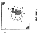
- FIG. 2 illustrates one example of a magnified pictoral view of the SSS chip 14.
- the (SSS) element 16 is illustrated mounted on a diaphragm 30.
- the diaphragm 30 includes an inner edge 32 and an outer edge 34.
- the (SSS) element 16 may be mounted on the inner edge 32 of the diaphragm.
- a maximum stress of the flexible membrane may occur on the inner edge 32 of the diaphragm 30, and thus, the (SSS) element 16 can be positioned to sense the maximum amount of stress, for example.
- Applied pressures to the diaphragm 30 will deflect a flexible membrane of the diaphragm 30, and these stresses in the membrane will change resistances of the (SSS) element 16.
- Such changes in resistance in the (SSS) element 16 will cause a change in output voltages of the (SSS) element 16 that are proportional to the applied pressures. For example, a small deflection in the flexible membrane of the diaphragm can be detected in a change in resistances within the (SSS) element 16.
- a thickness and diameter of the diaphragm 30, e.g., an aspect ratio of diaphragm, can be selected to be give rise to a certain deflection, which is equivalent to a certain change in resistance.
- a thick diaphragm may result in a small change in resistance on the (SSS) element 16 due to an applied pressure
- a thin diaphragm may result in a large change in resistance on the (SSS) element 16 from the applied pressure.
- Voltage outputs from the sensing (SSS) element 16 correspond to a certain pressure and temperature reading.
- the exact correspondence depends on the aspect ratio of the diaphragm 30, and a size of circuit elements relative to a strain localization. Other factors can also affect the correspondence between voltages and pressure/temperature readings.
- the (SSS) element 16 may be used in a medium pressure application, such as measuring 3.45 -20.7 MPa (500-3000 PSI) and in high temperature applications.
- the SSS chip 14 may comprise a silicon-on-insulator structure or a bulk silicon structure for example.
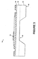
- Figure 3 illustrates a side view of one embodiment of the SSS chip 14.
- the SSS chip 14 includes legs 36 for connecting the diaphragm 30 to any circuit or other substrate.
- one or more of substrate layers e.g., layer 38
- the (SSS) element 16 is positioned on an inner edge of the diaphragm 30 as shown.
- Figure 4 is a flowchart depicting an example of functional blocks of a method for measuring pressure and temperature using the (SSS) element 16 element, for example, as illustrated in Figure 1 .
- the common sensing element has a tangential resistance when current flow is tangential to the common sensing element and a radial resistance when current flow is radial to the common sensing element.
- a current is applied tangentially through the common sensing element.
- a tangential voltage across the tangential resistance can then be measured, as shown at block 42.
- a current is applied radially through the common sensing element.
- a radial voltage across the radial resistance can then be measured, as shown at block 46.
- a magnitude of a pressure applied to the common sensing element and a magnitude of an ambient temperature of the common sensing element can be determined using the tangential voltage and the radial voltage, as shown at block 48.
- the order of the steps could also be 44, 46, 40, 42, for example.
- outputs of the SSS chip 14 can be associated with a pressure or temperature as applied to the (SSS) element 16.
- Two resistances can be measured across the square silicon element 16.
- a resistance for the condition where current flow is tangential to the square 16 is defined as the tangential resistance R t . This condition applies when SW1 is closed and SW2 is open.
- a resistance for the condition where current flow is radial to the square 16 is defined as the radial resistance R r . This condition applies when SW2 is closed and SW1 is open.
- V t 1 + d ⁇ R t R t ⁇ R t ⁇ I cc
- I cc the current applied from the constant current source
- d ⁇ R t Rt the tangential piezoresistive gage factor (e.g., constant value that relates a radial strain or deformation of the surface to the change in resistance and is dependent upon the properties of the materials of the sensor).
- V r 1 - d ⁇ R r R r ⁇ R r ⁇ I cc
- d ⁇ R r R r is the radial piezoresistive gage factor. is the radial piezoresistive gage factor.
- an applied pressure to the SSS chip 14 is proportional to the difference between the tangential and radial voltage measured across the SSS element 16.
- Equation (4) is that of a full Wheatstone bridge pressure sensor configuration operating with a constant voltage source of V ref .
- the sensing element 10 can provide the same pressure voltage output as that of full Wheatstone bridge sensors, but accomplishes such with a single piezo-resistive element rather than four, for example.
- VT V t + V r ⁇ 1 + d ⁇ R t R t ⁇ R t ⁇ I cc + 1 - d ⁇ R r R r ⁇ R r ⁇ I cc
- an ambient temperature of the SSS chip 14 is proportional to the sum of the tangential and radial voltage measured across the SSS element 16.
- using the same common sensing element, e.g., the SSS element 16 to measure both pressure and temperature lessens or eliminates any temperature gradient between the pressure and temperature signal since the same measurements of the same element are used for both. For example, compensations of pressure measurements using the temperature measurements may be more accurate since the pressure and temperature measurements originate from the same sensing element.
- a power polarity switching technique can be applied to the current source 12.
- the current source 12 provides power in a radial and tangential direction.
- the current source 12 could be arranged to provide power having a positive and negative polarity.
- the current source 12 could then apply power to the the (SSS) element 16 in a radial direction having a positive polarity, then in the radial direction having a negative polarity, and same for the tangential direction.
- Table 1 below describes one timing cycle that may be used.
- Table 1 SW1 SW2 SW3 SW4 Sensor Measurement Open Closed + + Radial Positive Open Closed - - Radial Negative Closed Open + + Tangential Positive Closed Open - - Tangential Negative As shown, when SW1 is open and SW2 is closed, power is provided in the radial direction, and when SW1 is closed and SW2 is open, power is provided in the tangential direction. Thus, by changing the polarity using SW3 and SW4, the PUD can be reduced.
- the power can be applied in substantially equal amounts of time for each polarity so that overall, the polarity changes will cancel out by providing power to the the (SSS) element 16 over the four combinations of switches.
- Measurements can be taken at any points, for example, by recording individual radial positive measurements, and radial negative measurements, and averaging each, respectively. Alternatively, a running average of the last ten measurements, for example, can continually be calculated. Other examples are possible as well.
- the current source 12 may include a controller for controlling the switching.
- the controller can be a microprocessor suitably programmed to use an algorithm to periodically close the switches, provide a period of time for outputs to stabilize, obtain a reading and provide a signal at an output which is representative of the pressure/temperature being sensed, open switch for a second period of time, and then repeat this sequence to provide updated measurements as desired.
- the SSS sensor described within many embodiments herein can be used to reduce a complexity of typical Wheatstone bridge sensors, to increase pressure sensitivity and reduce on-chip voltage, which reduces average power usage, and to reduce thermal gradients between pressure and temperature measurements, for example.
- the electric fields within the SSS will be reversed so that a net drift of mobile ions over time within the sensor is negligible.
- outputs of the SSS may be more accurate, for example, since any effects mobile ions have upon sensor output voltages will be essentially removed due to the net effect of any ion drift.
- the sensor may be used for applications that require the sensor to meet specifications within a very short time, (for example, a few seconds or less,) after power is applied since the power-up-drift phenomena within the SSS may be reduced.
Landscapes
- Physics & Mathematics (AREA)
- General Physics & Mathematics (AREA)
- Chemical & Material Sciences (AREA)
- Analytical Chemistry (AREA)
- Measuring Fluid Pressure (AREA)
- Indication And Recording Devices For Special Purposes And Tariff Metering Devices (AREA)
- Measuring Temperature Or Quantity Of Heat (AREA)
Applications Claiming Priority (1)
| Application Number | Priority Date | Filing Date | Title |
|---|---|---|---|
| US11/272,306 US7284438B2 (en) | 2005-11-10 | 2005-11-10 | Method and system of providing power to a pressure and temperature sensing element |
Publications (3)
| Publication Number | Publication Date |
|---|---|
| EP1785709A2 EP1785709A2 (en) | 2007-05-16 |
| EP1785709A3 EP1785709A3 (en) | 2008-07-02 |
| EP1785709B1 true EP1785709B1 (en) | 2011-10-26 |
Family
ID=37668188
Family Applications (1)
| Application Number | Title | Priority Date | Filing Date |
|---|---|---|---|
| EP06123804A Not-in-force EP1785709B1 (en) | 2005-11-10 | 2006-11-10 | Method and system of providing power to a pressure and temperature sensing element |
Country Status (3)
| Country | Link |
|---|---|
| US (1) | US7284438B2 (enExample) |
| EP (1) | EP1785709B1 (enExample) |
| JP (1) | JP2007132947A (enExample) |
Families Citing this family (5)
| Publication number | Priority date | Publication date | Assignee | Title |
|---|---|---|---|---|
| US9429479B2 (en) * | 2012-07-18 | 2016-08-30 | Millar Instruments | Methods, devices, and systems which determine a parameter value of an object or an environment from a voltage reading associated with a common mode signal of a balanced circuit |
| DE112014002776T5 (de) | 2013-06-11 | 2016-03-17 | Danfoss A/S | Dünnschichtsensor |
| EP2866012A1 (en) * | 2013-10-23 | 2015-04-29 | Danfoss A/S | A sensor element comprising a constraining layer |
| US10557770B2 (en) * | 2017-09-14 | 2020-02-11 | Sensata Technologies, Inc. | Pressure sensor with improved strain gauge |
| CN111721469A (zh) * | 2020-06-17 | 2020-09-29 | 中国计量大学 | 一种高灵敏度微型皮拉尼计 |
Family Cites Families (15)
| Publication number | Priority date | Publication date | Assignee | Title |
|---|---|---|---|---|
| US3123788A (en) * | 1964-03-03 | Piezoresistive gage | ||
| US4321832A (en) * | 1980-03-07 | 1982-03-30 | Rockwell International Corporation | High accuracy measuring apparatus |
| US4317126A (en) * | 1980-04-14 | 1982-02-23 | Motorola, Inc. | Silicon pressure sensor |
| US4399707A (en) * | 1981-02-04 | 1983-08-23 | Honeywell, Inc. | Stress sensitive semiconductor unit and housing means therefor |
| US4539843A (en) * | 1983-12-05 | 1985-09-10 | Aerologic, Inc. | Altimeter and vertical speed indicator |
| US5349867A (en) * | 1991-12-02 | 1994-09-27 | Kavlico Corporation | Sensitive resistive pressure transducer |
| US5469070A (en) * | 1992-10-16 | 1995-11-21 | Rosemount Analytical Inc. | Circuit for measuring source resistance of a sensor |
| DE4417228A1 (de) * | 1994-05-17 | 1995-11-23 | Michael Dr Altwein | Dehnungsmeßstreifen-Meßanordnung, Verwendung derselben und Modulationsverstärker für derartige Meßanordnungen |
| DE69528775T2 (de) * | 1994-12-20 | 2003-07-03 | The Foxboro Co., Foxboro | AC Speisung eines Polysilizium Druckwandlers |
| FR2757942A1 (fr) * | 1996-12-31 | 1998-07-03 | Motorola Semiconducteurs | Ensemble capteur et procede de polarisation d'un capteur travaillant en presence d'humidite |
| JP2000041684A (ja) | 1998-07-29 | 2000-02-15 | Daicel Chem Ind Ltd | 新規なd−アミノアシラーゼおよびその製造方法、並びに該d−アミノアシラーゼを利用したd−アミノ酸の製造方法 |
| US6065346A (en) * | 1999-03-29 | 2000-05-23 | Honeywell Inc. | Measurement system utilizing a sensor formed on a silicon on insulator structure |
| DE10160794B4 (de) * | 2001-12-11 | 2006-07-27 | Parker Hannifin Gmbh | Signalverarbeitungseinrichtung für einen Druckschalter od. dgl. |
| US6510742B1 (en) * | 2001-12-18 | 2003-01-28 | Honeywell International Inc. | Sensor formed on silicon on insulator structure and having reduced power up drift |
| US7278319B2 (en) | 2005-11-10 | 2007-10-09 | Honeywell International Inc. | Pressure and temperature sensing element |
-
2005
- 2005-11-10 US US11/272,306 patent/US7284438B2/en not_active Expired - Fee Related
-
2006
- 2006-11-10 JP JP2006305166A patent/JP2007132947A/ja not_active Withdrawn
- 2006-11-10 EP EP06123804A patent/EP1785709B1/en not_active Not-in-force
Also Published As
| Publication number | Publication date |
|---|---|
| EP1785709A3 (en) | 2008-07-02 |
| EP1785709A2 (en) | 2007-05-16 |
| JP2007132947A (ja) | 2007-05-31 |
| US20070113667A1 (en) | 2007-05-24 |
| US7284438B2 (en) | 2007-10-23 |
Similar Documents
| Publication | Publication Date | Title |
|---|---|---|
| EP1785711B1 (en) | Pressure and Temperature Sensing Element | |
| EP0239094B1 (en) | Semiconductor strain gauge bridge circuit | |
| EP0533389B1 (en) | Amplified pressure transducer | |
| EP3080572B1 (en) | Semiconductor pressure sensor | |
| US5424650A (en) | Capacitive pressure sensor having circuitry for eliminating stray capacitance | |
| US6931938B2 (en) | Measuring pressure exerted by a rigid surface | |
| US4333349A (en) | Binary balancing apparatus for semiconductor transducer structures | |
| EP0803054B1 (en) | A temperature compensation method in pressure sensors | |
| US10031039B2 (en) | Compensated pressure sensors | |
| EP1625372B1 (en) | Integrated resistor network for multi-functional use in constant current or constant voltage operation of a pressure sensor | |
| US20020086460A1 (en) | Pressure transducer employing on-chip resistor compensation | |
| JPH03233975A (ja) | 半導体センサ | |
| US7597005B2 (en) | Pressure sensor housing and configuration | |
| EP1785709B1 (en) | Method and system of providing power to a pressure and temperature sensing element | |
| US7284440B2 (en) | Line pressure compensated differential pressure transducer assembly | |
| JPH06186103A (ja) | センサー端子切替手段、並びに磁気測定方法若しくは圧力測定方法 | |
| JP7816938B2 (ja) | 圧力センサ | |
| JPH0534182A (ja) | 歪・温度複合センサ | |
| JP2689744B2 (ja) | 複合センサとそれを用いた複合伝送器とプラントシステム | |
| US11747379B2 (en) | Active measurement correction of resistive sensors | |
| JPS6255629B2 (enExample) | ||
| JP2948958B2 (ja) | トランスジューサ回路 | |
| JPS60100026A (ja) | 半導体圧力センサ | |
| JPH0476047B2 (enExample) | ||
| CN117405281A (zh) | 电阻电桥偏移补偿的温度系数 |
Legal Events
| Date | Code | Title | Description |
|---|---|---|---|
| PUAI | Public reference made under article 153(3) epc to a published international application that has entered the european phase |
Free format text: ORIGINAL CODE: 0009012 |
|
| AK | Designated contracting states |
Kind code of ref document: A2 Designated state(s): AT BE BG CH CY CZ DE DK EE ES FI FR GB GR HU IE IS IT LI LT LU LV MC NL PL PT RO SE SI SK TR |
|
| AX | Request for extension of the european patent |
Extension state: AL BA HR MK YU |
|
| PUAL | Search report despatched |
Free format text: ORIGINAL CODE: 0009013 |
|
| AK | Designated contracting states |
Kind code of ref document: A3 Designated state(s): AT BE BG CH CY CZ DE DK EE ES FI FR GB GR HU IE IS IT LI LT LU LV MC NL PL PT RO SE SI SK TR |
|
| AX | Request for extension of the european patent |
Extension state: AL BA HR MK RS |
|
| 17P | Request for examination filed |
Effective date: 20081223 |
|
| 17Q | First examination report despatched |
Effective date: 20090130 |
|
| AKX | Designation fees paid |
Designated state(s): DE FR GB |
|
| GRAP | Despatch of communication of intention to grant a patent |
Free format text: ORIGINAL CODE: EPIDOSNIGR1 |
|
| GRAS | Grant fee paid |
Free format text: ORIGINAL CODE: EPIDOSNIGR3 |
|
| GRAA | (expected) grant |
Free format text: ORIGINAL CODE: 0009210 |
|
| AK | Designated contracting states |
Kind code of ref document: B1 Designated state(s): DE FR GB |
|
| REG | Reference to a national code |
Ref country code: GB Ref legal event code: FG4D |
|
| REG | Reference to a national code |
Ref country code: DE Ref legal event code: R096 Ref document number: 602006025395 Country of ref document: DE Effective date: 20120105 |
|
| PLBE | No opposition filed within time limit |
Free format text: ORIGINAL CODE: 0009261 |
|
| STAA | Information on the status of an ep patent application or granted ep patent |
Free format text: STATUS: NO OPPOSITION FILED WITHIN TIME LIMIT |
|
| 26N | No opposition filed |
Effective date: 20120727 |
|
| REG | Reference to a national code |
Ref country code: DE Ref legal event code: R097 Ref document number: 602006025395 Country of ref document: DE Effective date: 20120727 |
|
| PGFP | Annual fee paid to national office [announced via postgrant information from national office to epo] |
Ref country code: DE Payment date: 20121130 Year of fee payment: 7 Ref country code: FR Payment date: 20121113 Year of fee payment: 7 |
|
| PGFP | Annual fee paid to national office [announced via postgrant information from national office to epo] |
Ref country code: GB Payment date: 20121025 Year of fee payment: 7 |
|
| GBPC | Gb: european patent ceased through non-payment of renewal fee |
Effective date: 20131110 |
|
| REG | Reference to a national code |
Ref country code: FR Ref legal event code: ST Effective date: 20140731 |
|
| PG25 | Lapsed in a contracting state [announced via postgrant information from national office to epo] |
Ref country code: DE Free format text: LAPSE BECAUSE OF NON-PAYMENT OF DUE FEES Effective date: 20140603 |
|
| REG | Reference to a national code |
Ref country code: DE Ref legal event code: R119 Ref document number: 602006025395 Country of ref document: DE Effective date: 20140603 |
|
| PG25 | Lapsed in a contracting state [announced via postgrant information from national office to epo] |
Ref country code: FR Free format text: LAPSE BECAUSE OF NON-PAYMENT OF DUE FEES Effective date: 20131202 Ref country code: GB Free format text: LAPSE BECAUSE OF NON-PAYMENT OF DUE FEES Effective date: 20131110 |
|
| P01 | Opt-out of the competence of the unified patent court (upc) registered |
Effective date: 20230525 |