EP1785618A1 - Kraftstoffkühlsystem für Verbrennungskraftmaschinen - Google Patents
Kraftstoffkühlsystem für Verbrennungskraftmaschinen Download PDFInfo
- Publication number
- EP1785618A1 EP1785618A1 EP06023298A EP06023298A EP1785618A1 EP 1785618 A1 EP1785618 A1 EP 1785618A1 EP 06023298 A EP06023298 A EP 06023298A EP 06023298 A EP06023298 A EP 06023298A EP 1785618 A1 EP1785618 A1 EP 1785618A1
- Authority
- EP
- European Patent Office
- Prior art keywords
- fuel
- pressure
- internal combustion
- combustion engines
- cooling system
- Prior art date
- Legal status (The legal status is an assumption and is not a legal conclusion. Google has not performed a legal analysis and makes no representation as to the accuracy of the status listed.)
- Granted
Links
Images


Classifications
-
- F—MECHANICAL ENGINEERING; LIGHTING; HEATING; WEAPONS; BLASTING
- F02—COMBUSTION ENGINES; HOT-GAS OR COMBUSTION-PRODUCT ENGINE PLANTS
- F02M—SUPPLYING COMBUSTION ENGINES IN GENERAL WITH COMBUSTIBLE MIXTURES OR CONSTITUENTS THEREOF
- F02M37/00—Apparatus or systems for feeding liquid fuel from storage containers to carburettors or fuel-injection apparatus; Arrangements for purifying liquid fuel specially adapted for, or arranged on, internal-combustion engines
- F02M37/20—Apparatus or systems for feeding liquid fuel from storage containers to carburettors or fuel-injection apparatus; Arrangements for purifying liquid fuel specially adapted for, or arranged on, internal-combustion engines characterised by means for preventing vapour lock
-
- F—MECHANICAL ENGINEERING; LIGHTING; HEATING; WEAPONS; BLASTING
- F02—COMBUSTION ENGINES; HOT-GAS OR COMBUSTION-PRODUCT ENGINE PLANTS
- F02M—SUPPLYING COMBUSTION ENGINES IN GENERAL WITH COMBUSTIBLE MIXTURES OR CONSTITUENTS THEREOF
- F02M21/00—Apparatus for supplying engines with non-liquid fuels, e.g. gaseous fuels stored in liquid form
- F02M21/02—Apparatus for supplying engines with non-liquid fuels, e.g. gaseous fuels stored in liquid form for gaseous fuels
- F02M21/0203—Apparatus for supplying engines with non-liquid fuels, e.g. gaseous fuels stored in liquid form for gaseous fuels characterised by the type of gaseous fuel
- F02M21/0209—Hydrocarbon fuels, e.g. methane or acetylene
- F02M21/0212—Hydrocarbon fuels, e.g. methane or acetylene comprising at least 3 C-Atoms, e.g. liquefied petroleum gas [LPG], propane or butane
-
- F—MECHANICAL ENGINEERING; LIGHTING; HEATING; WEAPONS; BLASTING
- F02—COMBUSTION ENGINES; HOT-GAS OR COMBUSTION-PRODUCT ENGINE PLANTS
- F02M—SUPPLYING COMBUSTION ENGINES IN GENERAL WITH COMBUSTIBLE MIXTURES OR CONSTITUENTS THEREOF
- F02M21/00—Apparatus for supplying engines with non-liquid fuels, e.g. gaseous fuels stored in liquid form
- F02M21/02—Apparatus for supplying engines with non-liquid fuels, e.g. gaseous fuels stored in liquid form for gaseous fuels
- F02M21/0218—Details on the gaseous fuel supply system, e.g. tanks, valves, pipes, pumps, rails, injectors or mixers
- F02M21/0221—Fuel storage reservoirs, e.g. cryogenic tanks
-
- F—MECHANICAL ENGINEERING; LIGHTING; HEATING; WEAPONS; BLASTING
- F02—COMBUSTION ENGINES; HOT-GAS OR COMBUSTION-PRODUCT ENGINE PLANTS
- F02M—SUPPLYING COMBUSTION ENGINES IN GENERAL WITH COMBUSTIBLE MIXTURES OR CONSTITUENTS THEREOF
- F02M21/00—Apparatus for supplying engines with non-liquid fuels, e.g. gaseous fuels stored in liquid form
- F02M21/02—Apparatus for supplying engines with non-liquid fuels, e.g. gaseous fuels stored in liquid form for gaseous fuels
- F02M21/0218—Details on the gaseous fuel supply system, e.g. tanks, valves, pipes, pumps, rails, injectors or mixers
- F02M21/023—Valves; Pressure or flow regulators in the fuel supply or return system
- F02M21/0239—Pressure or flow regulators therefor
-
- F—MECHANICAL ENGINEERING; LIGHTING; HEATING; WEAPONS; BLASTING
- F02—COMBUSTION ENGINES; HOT-GAS OR COMBUSTION-PRODUCT ENGINE PLANTS
- F02M—SUPPLYING COMBUSTION ENGINES IN GENERAL WITH COMBUSTIBLE MIXTURES OR CONSTITUENTS THEREOF
- F02M21/00—Apparatus for supplying engines with non-liquid fuels, e.g. gaseous fuels stored in liquid form
- F02M21/02—Apparatus for supplying engines with non-liquid fuels, e.g. gaseous fuels stored in liquid form for gaseous fuels
- F02M21/0218—Details on the gaseous fuel supply system, e.g. tanks, valves, pipes, pumps, rails, injectors or mixers
- F02M21/0245—High pressure fuel supply systems; Rails; Pumps; Arrangement of valves
-
- F—MECHANICAL ENGINEERING; LIGHTING; HEATING; WEAPONS; BLASTING
- F02—COMBUSTION ENGINES; HOT-GAS OR COMBUSTION-PRODUCT ENGINE PLANTS
- F02M—SUPPLYING COMBUSTION ENGINES IN GENERAL WITH COMBUSTIBLE MIXTURES OR CONSTITUENTS THEREOF
- F02M21/00—Apparatus for supplying engines with non-liquid fuels, e.g. gaseous fuels stored in liquid form
- F02M21/02—Apparatus for supplying engines with non-liquid fuels, e.g. gaseous fuels stored in liquid form for gaseous fuels
- F02M21/0218—Details on the gaseous fuel supply system, e.g. tanks, valves, pipes, pumps, rails, injectors or mixers
- F02M21/0287—Details on the gaseous fuel supply system, e.g. tanks, valves, pipes, pumps, rails, injectors or mixers characterised by the transition from liquid to gaseous phase ; Injection in liquid phase; Cooling and low temperature storage
-
- F—MECHANICAL ENGINEERING; LIGHTING; HEATING; WEAPONS; BLASTING
- F02—COMBUSTION ENGINES; HOT-GAS OR COMBUSTION-PRODUCT ENGINE PLANTS
- F02M—SUPPLYING COMBUSTION ENGINES IN GENERAL WITH COMBUSTIBLE MIXTURES OR CONSTITUENTS THEREOF
- F02M31/00—Apparatus for thermally treating combustion-air, fuel, or fuel-air mixture
- F02M31/20—Apparatus for thermally treating combustion-air, fuel, or fuel-air mixture for cooling
-
- F—MECHANICAL ENGINEERING; LIGHTING; HEATING; WEAPONS; BLASTING
- F02—COMBUSTION ENGINES; HOT-GAS OR COMBUSTION-PRODUCT ENGINE PLANTS
- F02M—SUPPLYING COMBUSTION ENGINES IN GENERAL WITH COMBUSTIBLE MIXTURES OR CONSTITUENTS THEREOF
- F02M37/00—Apparatus or systems for feeding liquid fuel from storage containers to carburettors or fuel-injection apparatus; Arrangements for purifying liquid fuel specially adapted for, or arranged on, internal-combustion engines
- F02M37/04—Feeding by means of driven pumps
- F02M37/08—Feeding by means of driven pumps electrically driven
- F02M37/10—Feeding by means of driven pumps electrically driven submerged in fuel, e.g. in reservoir
-
- F—MECHANICAL ENGINEERING; LIGHTING; HEATING; WEAPONS; BLASTING
- F02—COMBUSTION ENGINES; HOT-GAS OR COMBUSTION-PRODUCT ENGINE PLANTS
- F02M—SUPPLYING COMBUSTION ENGINES IN GENERAL WITH COMBUSTIBLE MIXTURES OR CONSTITUENTS THEREOF
- F02M55/00—Fuel-injection apparatus characterised by their fuel conduits or their venting means; Arrangements of conduits between fuel tank and pump F02M37/00
- F02M55/007—Venting means
-
- F—MECHANICAL ENGINEERING; LIGHTING; HEATING; WEAPONS; BLASTING
- F02—COMBUSTION ENGINES; HOT-GAS OR COMBUSTION-PRODUCT ENGINE PLANTS
- F02M—SUPPLYING COMBUSTION ENGINES IN GENERAL WITH COMBUSTIBLE MIXTURES OR CONSTITUENTS THEREOF
- F02M63/00—Other fuel-injection apparatus having pertinent characteristics not provided for in groups F02M39/00 - F02M57/00 or F02M67/00; Details, component parts, or accessories of fuel-injection apparatus, not provided for in, or of interest apart from, the apparatus of groups F02M39/00 - F02M61/00 or F02M67/00; Combination of fuel pump with other devices, e.g. lubricating oil pump
- F02M63/02—Fuel-injection apparatus having several injectors fed by a common pumping element, or having several pumping elements feeding a common injector; Fuel-injection apparatus having provisions for cutting-out pumps, pumping elements, or injectors; Fuel-injection apparatus having provisions for variably interconnecting pumping elements and injectors alternatively
- F02M63/0225—Fuel-injection apparatus having a common rail feeding several injectors ; Means for varying pressure in common rails; Pumps feeding common rails
-
- F—MECHANICAL ENGINEERING; LIGHTING; HEATING; WEAPONS; BLASTING
- F17—STORING OR DISTRIBUTING GASES OR LIQUIDS
- F17C—VESSELS FOR CONTAINING OR STORING COMPRESSED, LIQUEFIED OR SOLIDIFIED GASES; FIXED-CAPACITY GAS-HOLDERS; FILLING VESSELS WITH, OR DISCHARGING FROM VESSELS, COMPRESSED, LIQUEFIED, OR SOLIDIFIED GASES
- F17C2223/00—Handled fluid before transfer, i.e. state of fluid when stored in the vessel or before transfer from the vessel
- F17C2223/01—Handled fluid before transfer, i.e. state of fluid when stored in the vessel or before transfer from the vessel characterised by the phase
- F17C2223/0146—Two-phase
- F17C2223/0153—Liquefied gas, e.g. LPG, GPL
-
- F—MECHANICAL ENGINEERING; LIGHTING; HEATING; WEAPONS; BLASTING
- F17—STORING OR DISTRIBUTING GASES OR LIQUIDS
- F17C—VESSELS FOR CONTAINING OR STORING COMPRESSED, LIQUEFIED OR SOLIDIFIED GASES; FIXED-CAPACITY GAS-HOLDERS; FILLING VESSELS WITH, OR DISCHARGING FROM VESSELS, COMPRESSED, LIQUEFIED, OR SOLIDIFIED GASES
- F17C2265/00—Effects achieved by gas storage or gas handling
- F17C2265/06—Fluid distribution
- F17C2265/066—Fluid distribution for feeding engines for propulsion
-
- Y—GENERAL TAGGING OF NEW TECHNOLOGICAL DEVELOPMENTS; GENERAL TAGGING OF CROSS-SECTIONAL TECHNOLOGIES SPANNING OVER SEVERAL SECTIONS OF THE IPC; TECHNICAL SUBJECTS COVERED BY FORMER USPC CROSS-REFERENCE ART COLLECTIONS [XRACs] AND DIGESTS
- Y02—TECHNOLOGIES OR APPLICATIONS FOR MITIGATION OR ADAPTATION AGAINST CLIMATE CHANGE
- Y02T—CLIMATE CHANGE MITIGATION TECHNOLOGIES RELATED TO TRANSPORTATION
- Y02T10/00—Road transport of goods or passengers
- Y02T10/10—Internal combustion engine [ICE] based vehicles
- Y02T10/12—Improving ICE efficiencies
-
- Y—GENERAL TAGGING OF NEW TECHNOLOGICAL DEVELOPMENTS; GENERAL TAGGING OF CROSS-SECTIONAL TECHNOLOGIES SPANNING OVER SEVERAL SECTIONS OF THE IPC; TECHNICAL SUBJECTS COVERED BY FORMER USPC CROSS-REFERENCE ART COLLECTIONS [XRACs] AND DIGESTS
- Y02—TECHNOLOGIES OR APPLICATIONS FOR MITIGATION OR ADAPTATION AGAINST CLIMATE CHANGE
- Y02T—CLIMATE CHANGE MITIGATION TECHNOLOGIES RELATED TO TRANSPORTATION
- Y02T10/00—Road transport of goods or passengers
- Y02T10/10—Internal combustion engine [ICE] based vehicles
- Y02T10/30—Use of alternative fuels, e.g. biofuels
Definitions
- the invention describes a system for cooling fuel in internal combustion engines, in particular spark-ignited piston engines with cyclic internal combustion and direct injection of liquefied petroleum gas in liquid state or other liquid fuels in the combustion chamber.
- the prior art in the fuel supply direct injection gasoline engines is a demand-controlled fuel system consisting of a low-pressure and a high-pressure part, with the advantage of promoting only as much fuel as the engine just needed, whereby mechanical and electrical drive power is saved. This reduces the heat input into the fuel and saves fuel.
- the high-pressure fuel pump is a mechanically driven, quantity-controlled single-cylinder fuel pump which only supplies fuel as much fuel to the fuel distributor as is required for injection.
- These high pressure pumps are without backflow. In the most recent form even eliminates a leakage line. Excess fuel is pumped back internally into the supply line of the low-pressure side.
- This configuration is designed for and optimized for the fuel gasoline, especially as a temporary increase in the fuel pressure in critical operating conditions such as cold or hot start the vapor formation of the gasoline gas is suppressed. This ensures the operability of the engine in all operating conditions, even at temperatures above 70 ° C on the high-pressure housing.
- an additional cooling device for the fuel cooling in the low-pressure fuel system which refers to their cooling effect either from the refrigerant of an air conditioner or from the cooling effect of evaporating fuel.
- this cooling device can not sufficiently develop its effect in the above-described high-pressure fuel pumps, since the throughput of fuel mass by the fuel consumption of the internal combustion engine alone is too low to secure a sufficient cooling effect in all operating states of the internal combustion engine.
- the object of the invention is to improve a Kraftstoffvoriersystem of the type mentioned in that the disadvantages mentioned are eliminated and thereby a more effective, more stable and influenced fuel cooling is achieved.
- the thermally critical point in the Kraftstoffzu operationssystcm the internal combustion engine is the low pressure region of the high-pressure fuel pump and there especially the input to the high-pressure chamber in the region of the intake valve.
- this critical point becomes continuous and comprehensively cooled by passing fuel, thereby avoiding fuel vapor bubbles at the entrance of the high pressure space with subsequent engine stall.
- the cooling effect is particularly effectively reinforced and stabilized if the fuel has flowed through a cooler before entering the high-pressure pump. If this cooler is coupled as a heat exchanger to an air conditioner, the cooling effect increases. If one uses the fuel temperature as a controlled variable in the control loop of an air conditioning system, then it is possible to adjust the temperature of the fuel in the fuel supply to a desired optimum value.
- FIG. 1 shows schematically the hydraulic circuit of Krafstoffzu operationssystems with a coupling of the fuel return line 13 to the filling line 15.
- pressure-resistant tank for liquefied gas 1 2 liquefied gas is pressed through the fuel supply line 7 to the high-pressure fuel pump 11 by two successive low-pressure fuel pumps , On its way to the high-pressure pump 11 , the liquefied gas passes after the Tankabsperrventil 3 the pressure-resistant fuel filter 5, then connected to a (not shown here) air conditioning, heat exchanger 6 and a check valve 4.
- the heat exchanger is here the location of a fuel temperature control loop, the sets the optimum fuel flow temperature.
- the Ruckschlagvenlil 4 maintains the system pressure in the fuel flow even after stopping the engine and protects the fuel filter 5 and the heat exchanger 6 against pressure surges in the case of blowing fuel through the pressure relief valve 9 in the high-pressure 8th
- the high-pressure fuel pump 11 presses the part of the fuel calculated by the injection control via the high-pressure line 16 into the fuel rail 8 . From there, the fuel is injected via injection valves 17 directly and fluidly into the combustion chamber (not shown here) of the internal combustion engine.
- a pressure control valve 12 in the return line 13 ensures that the fuel pressure remains high enough for the fuel to remain liquid on its way through the high-pressure pump 11, in spite of the heat input occurring through heat conduction from the motor housing and the high-pressure generation.
- the return line 18, which branches off from the return line 13 downstream of the pressure regulating valve 12 is returned to the spring chamber 19 of the pressure regulating valve. This causes the Fe chamber 19 is acted upon by the pressure prevailing in the fuel tank 1 evaporation pressure and the hydraulic resistance changes analogously to the evaporation pressure.
- a check valve 14 blocks the liquefied petroleum gas from the liquefied gas tank 1.
- the return line 13 is coupled to the filling device 15 of the liquefied gas tank 1 . As a result, the separate introduction of the return line 13 in the fuel tank 1 is unnecessary .
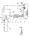
- FIG. 2 shows a variant of the hydraulic circuit of the fuel supply system shown in Figure 1 in which the remindlomis effet 13 is returned separately into the liquid tank 1 and accommodated in this tank 1 hydraulic resistance 12, whose spring chamber is acted upon directly with the vapor pressure of the liquid gas in the tank 1 , This saves the return line 18 into the spring chamber and guarantees that the cooling effect of the partially evaporating fuel completely benefits its cooling, without pressure fluctuations due to vapor bubbles in the return line 13
- FIG. 3 schematically shows an embodiment for the path of the fuel through the high-pressure pump 11.
- a quantity-controlled, piston surface-equal, mechanically driven single-piston high-pressure fuel pump 11 is shown .
- a further bore to the lower pump sub-chamber 60 The drain hole 130 allows the fuel to drain into the low pressure return line 13 below the pump chamber 60 .
Landscapes
- Engineering & Computer Science (AREA)
- Chemical & Material Sciences (AREA)
- Combustion & Propulsion (AREA)
- Mechanical Engineering (AREA)
- General Engineering & Computer Science (AREA)
- Chemical Kinetics & Catalysis (AREA)
- General Chemical & Material Sciences (AREA)
- Oil, Petroleum & Natural Gas (AREA)
- Fuel-Injection Apparatus (AREA)
- Liquid Carbonaceous Fuels (AREA)
- Output Control And Ontrol Of Special Type Engine (AREA)
- Cooling, Air Intake And Gas Exhaust, And Fuel Tank Arrangements In Propulsion Units (AREA)
Abstract
Description
- Die Erfindung beschreibt ein System zur Kühlung von Kraftstoff bei Verbrennungskraftmaschinen, insbesondere fremdgezündete Kolbenmaschinen mit zyklischer innerer Verbrennung und Direkteinspritzung von Flüssiggas in flüssigem Aggregatzustand oder anderer flüssiger Kraftstoffe in den Brennraum.
- Stand der Technik bei der Kraftstoffzuführung direkt einspritzender Ottomotoren ist ein bedarfsgeregeltes Kraftstoffsystem, bestehend aus einem Niederdruck- und einem Hochdruckteil, mit dem Vorteil, immer nur soviel Kraftstoff zu fördern, wie der Motor gerade benötigt, wodurch mechanische und elektrische Antriebsleistung gespart wird. Dies verringert den Wärmeeintrag in den Kraftstoff und spart Kraftstoff.
- Die Hochdruckkraftstoffpumpe ist in der Regel eine mechanisch angetriebene, mengengeregelte Einzylinder-Kraftstoffpumpe, die kennfeldgeregelt nur soviel Kraftstoff in den Kraftstoffverteiler pumpt, wie für die Einspritzung benötigt wird. Diese Hochdruckpumpen sind rücklauflos. In der aktuellsten Form entfällt sogar eine Leckageleitung. Überschüssiger Kraftstoff wird intern in den Vorlauf der Niederdruckseite zurückgepumpt.
- Diese Konfiguration ist ausgelegt auf den Kraftstoff Benzin und für diesen optimiert, zumal durch vorübergehende Erhöhung des Kraftstoffvordruckes in kritischen Betriebszuständen wie Kalt- oder Heißstart die Dampfblasenbildung des Kraftstoffes Benzin unterdrückt wird. Dadurch ist die Betriebsfähigkeit des Motors in allen Betriebszuständen gewährleistet, selbst bei Temperaturen am Hochdruckgehäuse von über 70°C.
- Für den Kraftstoff Flüssiggas (LPG) sind diese Temperaturen aber zu hoch um Verdampfung im Kraftstoffvorlauf mit vertretbarem konstruktivem Aufwand sicher zu verhindern. Insbesondere die Temperaturen beim Heißstart sind derart hoch, dass ein Heißstart wegen Kraftstoffdampfblasen in den Leitungen und den Kraftstoffpumpen mit dem Kraftstoff Flüssiggas praktisch nicht möglich ist.
- Auch ist es bei direkt einspritzendern Betrieb von Ottomotoren mit Flüssiggas im flüssigen Aggregatzustand anzustreben mit einer niedrigeren Kraftstofftemperatur im Vorfördersystem zu arbeiten als beim Betrieb mit dem Kraftstoff Benzin, damit sich der Druckbedarf, der durch den höheren Verdampfungsdruck von Flüssiggas von vornherein höher ist als beim Kraftstoff Benzin, im Kraftstoffvorfördersystem verringert und sich in einer Größenordnung bewegt, die mit konstruktiven Mitteln bei wirtschaftlich vertretbarem Aufwand gut zu beherrschen ist. Zusätzlich erhöht eine niedrigere Kraftstofftemperatur die Dichte des Kraftstoffs, was bei ausgeführten Fahrzeugen zu einer Leistungserhöhung führte. Außerdem ist eine größere Kraftstoffdichte vorteilhaft hinsichtlich des begrenzten Zeitfensters für die Kraftstoffeinspritzung bei Direkteinspritzung, weil ich dadurch im gleichen Zeitraum mehr Kraftstoffmasse in den Brennraum einbringen kann
- Ein weiterer, nicht zu vernachlässigender Nachteil höherer Kraftstofftemperaturen ist die Verringerung der inneren Kühlung beim Einspritzen in den Brennraum mit ungünstigen Folgcn für die Verdichtung oder den optimalen Zündzeitpunkt.
- In der
DE 101 46 051 ist deshalb eine zusätzliche Kühlvorrichtung für die Kraftstoffkühlung im Kraftstoffniederdruckssystem beschrieben, die ihre Kühlwirkung entweder aus dem Kältemittel einer Klimaanlage oder aus der Kühlwirkung verdampfenden Kraftstoffes bezieht. Diese Kühlvorrichtung kann jedoch ihre Wirkung bei den oben beschriebenen Kraftstoffhochdruckpumpen nicht ausreichend entfalten, da der Durchsatz an Kraftstoffmasse durch den Kraftstoffverbrauch der Brennkraftmaschine allein zu gering ist um eine hinreichende Kühlwirkung in allen Betriebszuständen der Verbrennungskraftmaschine zu sichern. - Gleiches gilt auch für die in
DE 10 2004 060 450.9 vorgeschlagene Lösung. - In der
DE 103 20 558.6 ist deshalb für die herkömmliche Konfiguration des Kraftstoffvorfördersystems als Lösung des Verdampfungsproblems von Flüssiggas durch zu hohe Kraftstofftemperaturen vorgeschlagen, dass bei Überschreitung einer definierten Temperatur, aus-gelöst durch einen Temperatursensor, automatisch von dem Kraftstoff Flüssiggas auf den Kraftstoff Benzin umgeschaltet wird. Die Verwendung von Flüssiggas als einzigem Betriebskraftstoff ist dadurch jedoch ausgeschlossen. Auch unter wirtschaftlichen Gesichtspunkten ist diese Lösung von Nachteil. - Aufgabe der Erfindung ist es, ein Kraftstoffvorfördersystem der eingangs genannten Art dahingehend zu verbessern, dass die genannten Nachteile behoben werden und dadurch eine effektivere, stabilere und beeinflußbare Kraftstoffkühlung erreicht wird.
- Diese Aufgabe wird durch einen Gegenstand mit den Merkmalen des Anspruchs 1 gelöst. Vorteilhafte Ausführungsformen finden sich in den abhängigen Ansprüchen.
- Die wärmemäßig kritische Stelle im Kraftstoffzuführungssystcm der Verbrennungskraftmaschine ist der Niederdruckbereich der Kraftstoffhochdruckpumpe und da besonders der Eingang zur Hochdruckkammer im Bereich des Einlassventils. Durch die erfindungsgemäße, vorteilhafte Herstellung der Rücklaufeinrichtung, einschließend den Anschluss für die Rücklaufleitung als Teil des Niederdruckbereiches, wird diese kritische Stelle kontinuierlich und umfassend von vorbeifließendem Kraftstoff gekühlt, wodurch Kraftstoffdampfblasen am Eingang des Hochdruckraumes mit nachfolgenden Stillstand des Motors vermieden werden.
- Besonders wirkungsvoll verstärkt und stabilisiert wird der kühlende Effekt, wenn der Kraftstoff vor Eintritt in die Hochdruckpumpe durch einen Kühler geflossen ist. Wird dieser Kühler als Wärmetauscher an eine Klimaanlage gekoppelt, verstärkt sich der Kühleffekt. Verwendet man die Kraftstofftemperatur als Regelgröße im Regelkreis einer Klimaanlage, dann ist es möglich, die Temperatur des Kraftstoffes im Kraftstoffvorlauf auf einen gewünschten optimalen Wert einzuregeln.
- Diese Probleme werden durch die in den Patentansprüchen aufgeführten Merkmale gelöst, indem die vorliegenden Erfindung bewirkt, dass
- a) durch den kühlenden, kontinuierlichen Fluss einer großen Kraftstoffmasse durch den erfindungsgemäß veränderten Niederdruckbereich der Kraftstoffhochdruckpumpe die Kraftstofftemperatur in allen Betriebsmodi niedrig bleibt,
- b) sich durch die Leistungsregelung der Kraftstoffvorförderpumpe(n) die Kraftstoffvorlauftemperatur in gewünschter Weise beeinflussen lässt,
- c) durch den Anschluss an ein regelbares Zusatzkühlsystem, wie eine Klimaanlage, die Vorlauftemperatur des Kraftstoffes in allen Betriebsmodi noch sichere und stabild, in einem definierten, optimalen Temperaturintervall gehalten wer den kann,
- d) durch die hydraulisch in Reihe geschalteten Kraftstoffvorförderpumpen auch bei einem Vorförderdruck größer als 10 bar eine hinreichend große Masse an Kraftstoff zur Deckung des Kühlbedarfs umgewälzt wird.
- e) die Kraftstoffhochdruckpumpe durch die kühlende Luft eines Kühlgebläses, welches seine Kühlluft aus dem kühlen Bereich eines Kühlers, vorzugsweise eines an die Klimaanlage angeschlossenen Wärmetauschers, absaugt, gekühlt wird und dadurch die Kraftstofftemperatur im Niederdruckbereich der Hochdruckpumpe niedrig hält.
- f) durch die, in allen Betriebszuständen ausreichende Kraftstoffkühlung, ein monovalenter Betrieb der Brennkraftmaschine mit direkt und flüssig in den Brennraum eingespritztem Flüssiggas möglich wird,
- g) durch die Beaufschlagung der Federkammer eines mechanischen Druckregelventils mit dem Tankdruck jede Temperaturerhöhung des Flüssiggases im Tank automatisch mit einer analogen Druckerhöhung des Kraftstoffvorfördersystems beantwortet wird.
- h) die Federkammer des im Tank untergebrachten Druckregelventils direkt, ohne eine zusätzliche Zuführungsleitunp, mit dem im Tank herrschenden Gasdruck beaufschlagt wird, wodurch die Rückführungsleitung gespart und der Montageaufwand verringert wird und
- i) sich die Kühlwirkung dadurch zusätzlich erhöht, weil dem im Rücklauf teilweise verdampfenden Kraftstoff im Tank ein vielfach größeres Ausdehnungsvolumen direkt zur Verfugung steht.
- Ausführungsbeispiel
- Es werden Ausführungsbeispiele in den Zeichnungen vereinfacht dargestellt und in der nachfolgenden Beschreibung erläutert.
- Es zeigen:
- Figur 1 die hydraulische Schaltung des Kraftstoffkühlsystems mit einer Koppelung des Kraftstoffrücklaufs an die Füllleitung.
- Figur 2 die hydraulische Schaltung des Kraftstoffzuführungssystems mit einer separaten Rückführungsleitung in den Flüssiggastank und dem in diesem Tank untergebrachten hydraulischen Widerstand
- Figur 3 den Durchfluss durch den Niederdruckbereich der Hochdruckkraftstoftpumpe
- Figur 1 zeigt schematisch die hydraulische Schaltung des Krafstoffzuführungssystems mit einer Koppelung des Kraftstoffrücklaufs 13 an die Füllleitung 15. Aus einem, mit den vorschriftsmäßigen Sicherheitsarmaturen versehenen, druckfesten Tank für Flüssiggas 1 wird durch zwei hintereinander geschaltete Kraftstoffniederdruckpumpen 2 Flüssiggas durch die Kraftstoffvorlaufleitung 7 zur Kraftstoffhochdruckpumpe 11 gedrückt. Auf seinem Weg zur Hochdruckpumpe 11. passiert das Flüssiggas nach dem Tankabsperrventil 3 den druckfesten Kraftstofffilter 5, danach den, an eine (hier nicht gezeigte) Klimaanlage angeschlossenen, Wärmetauscher 6 und ein Rückschlagventil 4. Der Wärmetauscher stellt hier den Stellort eines Kraftstofftemperaturregelkreises dar, der die optimale Kraftstoffvorlauftemperatur einstellt. Das Ruckschlagvenlil 4 hält den Systemdruck im Kraftstoffvorlauf auch nach Abstellen des Motors aufrecht und schützt den Kraftstofffilter 5 und den Wärmetauscher 6 vor Druckstößen im Falle des Abblasens von Kraftstoff durch das Überdruckventil 9 in der Hochdruckrail 8.
- Die Kraftstoffhochdruckpumpe 11 drückt den von der Einspritzregelung berechneten Teil des Kraftstoffes über die Hochdruckleitung 16 in die Kraftstoffleiste 8. Von dort aus wird der Kraftstoff über Einspritzventile 17 direkt und flüssig in den (hier nicht gezeigten) Brennraum der Verbrenztungskraftmaschine eingespritzt.
- Der überwiegende Teil des vorgeförderten Kraftstoffes fließt durch den Niederdruckteil 30 der Hochdruckpumpe 11 hindurch und wird über die Rücklaufleitung 13 anschließend wieder in den Flüssiggastank 1 zurückgeführt. Ein Druckregelventil 12 im Rücklauf 13 sorgt dafür, dass der Kraftstoffdruck so hoch bleibt, dass der Kraftstoff auf seinem Weg durch die Hochdruckpumpe 11, trotz des dabei stattfindenden Wärmeeintrages durch Wärmeleitung aus dem Motorgehäuse und die Hochdruckerzeugung, flüssig bleibt. Die Rückführungsleitung 18, die von der Rücklaufleitung 13 stromabwärts des Druckregelventils 12 abzweigt, wird in die Federkammer 19 des Druckregelventils zurückgeführt. Das bewirkt, dass die Fe-derkammer 19 mit dem im Kraftstofftank 1 herrschenden Verdampfungsdruck beaufschlagt wird und sich der hydraulische Widerstand analog dem Verdampfungsdruck verändert. Ein Rückschlagventil 14 versperrt dem Flüssiggas den Weg aus dem Flüssiggastank 1. Die Rücklaufleitung 13 ist bei diesem Ausführungsbeispiel an die Füllvorrichtung 15 des Flüssiggastankes 1 angekoppelt. Dadurch erübrigt sich die gesonderte Einbringung der Rücklaufleitung 13 in den Kraftstofftank 1.
- Figur 2 zeigt eine Variante der hydraulischen Schaltung des in Figur 1 dargestellten Kraftstoffzuführungssystems bei der die Rückführmigsleitung 13 separat in den Flüssiggastank 1 zurückgeführt wird und den in diesem Tank 1 untergebrachten hydraulischen Widerstand 12, dessen Federraum direkt mit dem Dampfdruck des Flüssiggas im Tank 1 beaufschlagt wird. Das spart die Rückführungsleitung 18 in die Federkammer und garantiert, dass die Kühlwirkung des teilweise verdampfenden Kraftstoffes vollständig seiner Kühlung zugute kommt, ohne Druckschwankungen durch Dampfblasen in der Rückleitung 13
- Figur 3 zeigt schematisch eine Ausführung für den Weg des Kraftstoffes durch die Hochdruckpumpe 11. Abgebildet ist eine mengengeregelte, kolbenflächengleiche, mechanisch angetriebene Ein-Kolben-Hochdruck-Kraftstoffpumpe 11. Über die Zuflussbohrung 20 fließt der Kraftstoff aus der Niederdruckvorlaufleitung 7 in den Niederdruckbereich 30. Bei geöffnetem Einlassventil 40 gelängt der Kraftstoff sowohl in den Pumpenraum 50 als auch über die Verbindungsbohrung 80 in den Pumpenunterraum 60 unter dem Pumpenkolben 70. Eine weitere Bohrung zum unteren Pumpenunterraum 60 hin, die Abflussbohrung 130, ermöglicht es dem Kraftstoff, unterhalb der Pumpenkammer 60 in die Niederdruckrücklaufleitung 13 abzufließen. Damit wird eine kontinuierliche Umströmung des Hochdruckpumpenraums 50 im Niederdruckbereich 30 der Kraftstoffbochdruckpumpe 11 erreicht, der die Abführung des Wärmeeintrages aus der Hochdruckpumpe 11 in den Kraftstoff bewirkt. Die hier abgebildete kolbenflächengleiche Variante einer Kraftstoffhochdruckpumpe 11 hat zusätzlich den Vorteil, dass sie den überschüssigen Kraftstoff im Pumpenraum 50 nicht gegen, den, im Flüssiggasbetrieb relativ hohen Vorförderdruck, zurückschieben muss, wodurch Antriebsenergie eingespart wird.
Claims (9)
- Kraftstoffkühlsystem für Verbrennungskraftmaschinen, aufweisend einen Kraftstofftank (1), einer mit diesem in Verbindung stehenden, über wenigstens eine Kraftstoffvorförderpumpe (2) und eine Kraftstoffvorlaufleitung (7) mit Kraftstoff beschickten Kraftstoffhoschdruckpumpe (11),
dadurch gekennzeichnet,
dass die Kraftstofmochdruckpumpe (11) eine Rücklaufeinrichtung (130) aufweist, die über eine, einen hydraulischen Widerstand (12) aufweisende, Kraftstoffrücklaufleitung (13) mit dem Kraftstofftank (1) so verbunden ist, dass ein kontinuierlicher, vom aktuellen Kraftstoffbedarf der Verbrennungskraftmaschine unabhängiger, Kraftstofffluss durch den Niederdruckbereich (30) der Kraftstoffhochdruckpumpe (11) zustande kommt. - Kraftstoffkühlsystem für Verbrennungskraftmaschinen nach Anspruch 1, dadurch gekennzeichnet, dass der hydraulische Widerstand (12) ein mechanisch arbeitendes Druckregelventil ist, dessen Federkammer (19) über eine Rückführungsleitung (18) mit dem, stromabwärts des Druckregelventils (12) entnommenen, Kraftstofftankdruck beaufschlagt wird.
- Kraftstoffkühlsystem für Verbrennungskraftmaschinen nach einem der vorhergehenden Ansprüche dadurch gekennzeichnet, dass der hydraulische Widerstand (12), im Flüssiggastank (1) platziert wird.
- Kraftstoffkühlsystem für Verbrennungskraftmaschinen nach einem der vorhergehenden Ansprüche, dadurch gekennzeichnet, dass in dem Kraftstofftank (1) zwei Kraftstoffvorförderpumpen (2), vorzugsweise elektrisch angetrieben, hydraulisch in Reihe geschaltet sind.
- Kraftstoffkühlsystem für Verbrennungskraftmaschinen nach einem der vorhergehenden Ansprüche dadurch gekennzeichnet, dass die Kraftstofftemperatur im Vorlauf durch eine Leistungsregelung der Kraftstoffvorförderpumpe(n) (2) beeinflusst wird.
- Kraftstoffkühlsystem für Verbrennungskraftmaschinen nach einem der vorhergehenden Ansprüche dadurch gekennzeichnet, dass im Kraftstoffvorlauf (7) zur Kraftstoffhochdruckpumpe (11) hin eine Kühlvorrichtung (6) angeschlossen ist, die den Kraftstoff zusätzlich kühlt.
- Krafstoffkühlsystem für Verbrennungskraftmaschinen nach Anspruch 6 dadurch gekennzeichnet, dass die Kraftstoffkühlvorrichtung (6) regelbar ist und dadurch die Kraftstoffvortauftempcratur in einem definierten Temperatuffenster hält.
- Kraftstoffkühlsystem für Verbrennungskraftmaschinen nach Anspruch 6 oder 7 dadurch gekennzeichnet, dass die Kühlvorrichtung (6) an eine Klimaanlage angeschlossen ist.
- Kraftstoffkühlsystem) für Verbrennungskraftmaschinen nach einem der vorhergehenden Ansprüche dadurch gekennzeichnet, dass die Kraftstoffhochdruckpumpe (11) durch ein Kühlluftgebläse, welches Kühlluft vorzugsweise aus der Umgebung eines Kühlers ansaugt, gekühlt wird.
Priority Applications (2)
| Application Number | Priority Date | Filing Date | Title |
|---|---|---|---|
| SI200630241T SI1785618T1 (sl) | 2005-11-13 | 2006-11-09 | Hladilni sistem goriva za stroje z notranjim izgorevanjem |
| PL06023298T PL1785618T5 (pl) | 2005-11-13 | 2006-11-09 | System chłodzenia paliwa do silników spalinowych |
Applications Claiming Priority (1)
| Application Number | Priority Date | Filing Date | Title |
|---|---|---|---|
| DE102005054451A DE102005054451A1 (de) | 2005-11-13 | 2005-11-13 | Kraftstoffkühlsystem für Verbrennungskraftmaschinen |
Publications (3)
| Publication Number | Publication Date |
|---|---|
| EP1785618A1 true EP1785618A1 (de) | 2007-05-16 |
| EP1785618B1 EP1785618B1 (de) | 2009-01-07 |
| EP1785618B2 EP1785618B2 (de) | 2020-01-15 |
Family
ID=37670942
Family Applications (1)
| Application Number | Title | Priority Date | Filing Date |
|---|---|---|---|
| EP06023298.0A Active EP1785618B2 (de) | 2005-11-13 | 2006-11-09 | Kraftstoffkühlsystem für Verbrennungskraftmaschinen |
Country Status (8)
| Country | Link |
|---|---|
| EP (1) | EP1785618B2 (de) |
| AT (1) | ATE420283T1 (de) |
| DE (3) | DE102005054451A1 (de) |
| DK (1) | DK1785618T3 (de) |
| ES (1) | ES2318650T5 (de) |
| PL (1) | PL1785618T5 (de) |
| PT (1) | PT1785618E (de) |
| SI (1) | SI1785618T1 (de) |
Cited By (9)
| Publication number | Priority date | Publication date | Assignee | Title |
|---|---|---|---|---|
| DE102007051677A1 (de) | 2007-10-26 | 2009-04-30 | Karlheinrich Winkelmann | Verfahren und Vorrichtung zur Erzeugung und Beförderung eines Mischkraftstoffes |
| DE102008024561A1 (de) | 2008-05-21 | 2009-11-26 | Karlheinrich Winkelmann | Verfahren zum Betreiben einer Verbrennungskraftmaschine |
| WO2010121305A1 (en) * | 2009-04-20 | 2010-10-28 | Dgc Industries Pty Ltd | A dual fuel supply system for an indirect-injection system of a diesel engine with off-board fuel mixing |
| WO2011130791A1 (en) * | 2010-04-20 | 2011-10-27 | Dgc Industries Pty Ltd | A dual fuel supply system for a direct-injection system of a diesel engine with on-board mixing |
| WO2014173646A1 (en) | 2013-04-23 | 2014-10-30 | Vialle Alternative Fuel Systems B.V. | Adaptor, assembly of an adaptor and accessory plate and kit for fitting a lpg fuel system for liquid injection in a car |
| WO2018166603A1 (en) | 2017-03-16 | 2018-09-20 | Volvo Truck Corporation | A fuel system for an internal combustion engine |
| EP3543518A1 (de) * | 2018-03-21 | 2019-09-25 | Motonic Corporation | Hochdruckkraftstoffpumpe und lpdi-system damit |
| CN110939531A (zh) * | 2018-09-21 | 2020-03-31 | 罗伯特·博世有限公司 | 用于内燃机的燃料输送装置 |
| DE102008056001B4 (de) | 2008-11-05 | 2022-04-21 | Vialle Group B.V. | Verbrennungskraftmaschine mit strömungsoptimierter Kraftstoffhochdruckpumpe |
Families Citing this family (10)
| Publication number | Priority date | Publication date | Assignee | Title |
|---|---|---|---|---|
| DE602007012451D1 (de) | 2006-09-25 | 2011-03-24 | Dgc Ind Pty Ltd | Zweistoffsystem |
| DE102008053873B4 (de) * | 2008-10-30 | 2012-08-30 | Vialle Alternative Fuel Systems B.V. | Verbrennungskraftmaschine und Verfahren zum Betreiben einer Verbrennungskraftmaschine |
| NL2003791C2 (nl) | 2009-11-12 | 2011-05-16 | Vialle Alternative Fuel Systems Bv | Brandstoftoevoersysteem en hogedrukpomp voor een verbrandingsmotor. |
| NL2006992C2 (en) | 2011-06-24 | 2013-01-02 | Indopar B V | Method of switching from a liquefied gas fuel to a liquid fuel being provided to a direct injection combustion engine, and direct injection bi-fuel system for such an engine. |
| DE102013203891A1 (de) | 2013-03-07 | 2014-09-11 | Robert Bosch Gmbh | Hochdruckpumpe, insbesondere Kraftstoffhochdruckpumpe für eine Brennkraftmaschine |
| US9482195B2 (en) | 2013-03-14 | 2016-11-01 | GM Global Technology Operations LLC | Fuel supply system for internal combustion engine and methods of using the same |
| DE102017113055A1 (de) * | 2017-06-14 | 2018-12-20 | Iav Gmbh Ingenieurgesellschaft Auto Und Verkehr | Gasdruckregler |
| FR3126736B1 (fr) * | 2021-09-03 | 2025-09-12 | Renault Sas | Pompe à haute pression d’un système de carburation à injection directe de carburant liquide d’un moteur à combustion interne à bicarburation d’un véhicule automobile |
| FR3128742B1 (fr) * | 2021-10-29 | 2025-06-13 | Renault Sas | Pompe à haute pression pour moteur à combustion interne de véhicule automobile |
| DE102024200122A1 (de) * | 2024-01-05 | 2025-07-10 | Robert Bosch Gesellschaft mit beschränkter Haftung | Verfahren zum Betreiben einer Pumpenanordnung für alternative Kraftstoffe, insbesondere für Methanol oder Ammoniak, sowie Pumpenanordnung |
Citations (4)
| Publication number | Priority date | Publication date | Assignee | Title |
|---|---|---|---|---|
| DE10146051A1 (de) * | 2001-01-28 | 2002-10-10 | Karlheinrich Winkelmann | Kraftstoffdirekteinspritzsystem |
| EP1293654A2 (de) * | 2001-09-18 | 2003-03-19 | Karlheinrich Winkelmann | Kraftstoff-Einspritzsystem für Brennkraftmaschinen |
| DE20310824U1 (de) * | 2003-07-14 | 2004-11-18 | Winkelmann, Karlheinrich, Dipl.-Ing. (TH) | Verbrennungskraftmaschine mit Hochdruckeinspritzung eines flüssigen Kraftstoffgemisches |
| DE10320558A1 (de) * | 2003-05-07 | 2004-11-25 | Entwicklungsbüro für Umweltfreundliche Technologien Dipl.-Ing. (TH) Karlheinrich Winkelmann | Einspritzregelung bei bivalenter Kraftstoffdirekteinspritzung |
-
2005
- 2005-11-13 DE DE102005054451A patent/DE102005054451A1/de not_active Ceased
-
2006
- 2006-11-09 PT PT06023298T patent/PT1785618E/pt unknown
- 2006-11-09 ES ES06023298T patent/ES2318650T5/es active Active
- 2006-11-09 AT AT06023298T patent/ATE420283T1/de active
- 2006-11-09 DE DE502006002566T patent/DE502006002566D1/de active Active
- 2006-11-09 SI SI200630241T patent/SI1785618T1/sl unknown
- 2006-11-09 EP EP06023298.0A patent/EP1785618B2/de active Active
- 2006-11-09 DK DK06023298T patent/DK1785618T3/da active
- 2006-11-09 DE DE200620021087 patent/DE202006021087U1/de not_active Expired - Lifetime
- 2006-11-09 PL PL06023298T patent/PL1785618T5/pl unknown
Patent Citations (4)
| Publication number | Priority date | Publication date | Assignee | Title |
|---|---|---|---|---|
| DE10146051A1 (de) * | 2001-01-28 | 2002-10-10 | Karlheinrich Winkelmann | Kraftstoffdirekteinspritzsystem |
| EP1293654A2 (de) * | 2001-09-18 | 2003-03-19 | Karlheinrich Winkelmann | Kraftstoff-Einspritzsystem für Brennkraftmaschinen |
| DE10320558A1 (de) * | 2003-05-07 | 2004-11-25 | Entwicklungsbüro für Umweltfreundliche Technologien Dipl.-Ing. (TH) Karlheinrich Winkelmann | Einspritzregelung bei bivalenter Kraftstoffdirekteinspritzung |
| DE20310824U1 (de) * | 2003-07-14 | 2004-11-18 | Winkelmann, Karlheinrich, Dipl.-Ing. (TH) | Verbrennungskraftmaschine mit Hochdruckeinspritzung eines flüssigen Kraftstoffgemisches |
Cited By (16)
| Publication number | Priority date | Publication date | Assignee | Title |
|---|---|---|---|---|
| DE102007051677A1 (de) | 2007-10-26 | 2009-04-30 | Karlheinrich Winkelmann | Verfahren und Vorrichtung zur Erzeugung und Beförderung eines Mischkraftstoffes |
| DE102008024561B4 (de) * | 2008-05-21 | 2015-01-08 | Vialle Alternative Fuel Systems B.V. | Verfahren zum Betreiben einer Verbrennungskraftmaschine |
| DE102008024561A1 (de) | 2008-05-21 | 2009-11-26 | Karlheinrich Winkelmann | Verfahren zum Betreiben einer Verbrennungskraftmaschine |
| DE102008056001B4 (de) | 2008-11-05 | 2022-04-21 | Vialle Group B.V. | Verbrennungskraftmaschine mit strömungsoptimierter Kraftstoffhochdruckpumpe |
| WO2010121305A1 (en) * | 2009-04-20 | 2010-10-28 | Dgc Industries Pty Ltd | A dual fuel supply system for an indirect-injection system of a diesel engine with off-board fuel mixing |
| WO2010121306A1 (en) * | 2009-04-20 | 2010-10-28 | Dgc Industries Pty Ltd | A dual fuel supply system for an indirect-injection system of a diesel engine |
| US9765707B2 (en) | 2009-04-20 | 2017-09-19 | Dgc Industries Pty Ltd | Dual fuel supply system for an indirect-injection system of a diesel engine |
| US8973560B2 (en) | 2010-04-20 | 2015-03-10 | Dgc Industries Pty Ltd | Dual fuel supply system for a direct-injection system of a diesel engine with on-board mixing |
| CN102939451B (zh) * | 2010-04-20 | 2016-08-03 | 工业私人有限公司 | 具有自载混合的用于柴油引擎直接喷射系统的双燃料供应系统 |
| CN102939451A (zh) * | 2010-04-20 | 2013-02-20 | 工业私人有限公司 | 具有自载混合的用于柴油引擎直接喷射系统的双燃料供应系统 |
| WO2011130791A1 (en) * | 2010-04-20 | 2011-10-27 | Dgc Industries Pty Ltd | A dual fuel supply system for a direct-injection system of a diesel engine with on-board mixing |
| WO2014173646A1 (en) | 2013-04-23 | 2014-10-30 | Vialle Alternative Fuel Systems B.V. | Adaptor, assembly of an adaptor and accessory plate and kit for fitting a lpg fuel system for liquid injection in a car |
| WO2018166603A1 (en) | 2017-03-16 | 2018-09-20 | Volvo Truck Corporation | A fuel system for an internal combustion engine |
| US10865740B2 (en) | 2017-03-16 | 2020-12-15 | Volvo Truck Corporation | Fuel system for an internal combustion engine |
| EP3543518A1 (de) * | 2018-03-21 | 2019-09-25 | Motonic Corporation | Hochdruckkraftstoffpumpe und lpdi-system damit |
| CN110939531A (zh) * | 2018-09-21 | 2020-03-31 | 罗伯特·博世有限公司 | 用于内燃机的燃料输送装置 |
Also Published As
| Publication number | Publication date |
|---|---|
| ATE420283T1 (de) | 2009-01-15 |
| ES2318650T3 (es) | 2009-05-01 |
| SI1785618T1 (sl) | 2009-06-30 |
| DK1785618T3 (da) | 2009-03-16 |
| ES2318650T5 (es) | 2020-09-18 |
| EP1785618B1 (de) | 2009-01-07 |
| PT1785618E (pt) | 2009-03-23 |
| EP1785618B2 (de) | 2020-01-15 |
| DE202006021087U1 (de) | 2012-06-11 |
| DE502006002566D1 (de) | 2009-02-26 |
| DE102005054451A1 (de) | 2007-05-16 |
| PL1785618T5 (pl) | 2021-08-02 |
| PL1785618T3 (pl) | 2009-06-30 |
Similar Documents
| Publication | Publication Date | Title |
|---|---|---|
| EP1785618B1 (de) | Kraftstoffkühlsystem für Verbrennungskraftmaschinen | |
| DE60208356T2 (de) | Kraftstoffzufuhrsystem | |
| EP3292289B1 (de) | Verfahren zum betreiben einer wassereinspritzvorrichtung für eine brennkraftmaschine | |
| DE102013211700B3 (de) | Fahrzeugheizsystem sowie Verfahren zum Heizen des Innenraums eines Fahrzeugs mit einem Fahrzeugheizsystem | |
| DE102008024561B4 (de) | Verfahren zum Betreiben einer Verbrennungskraftmaschine | |
| DE102012220168A1 (de) | System und Verfahren zum Umwälzen von Kraftstoff durch eine Direkteinspritzpumpe eines Bi-Fuel-Motors | |
| EP0966605A1 (de) | Kraftstoffeinspritzeinrichtung für brennkraftmaschinen | |
| DE19957742A1 (de) | Kraftstoffzuführvorrichtung für einen Verbrennungsmotor | |
| DE10146051B4 (de) | Kraftstoffdirekteinspritzsystem | |
| DE69008246T2 (de) | Wasserabscheidesystem für ein Kraftstoffeinspritzsystem. | |
| EP2601396B1 (de) | Verbrennungskraftmaschine mit flüssigen und gasförmigen kraftstoff | |
| DE102011120798A1 (de) | Thermostatventil in Drehschieberbauform | |
| DE4133287A1 (de) | Verdampfungsgekuehlte verbrennungskraftmaschine | |
| DE102006060300A1 (de) | Kraftstoffsystem für eine Brennkraftmaschine | |
| DE10005471A1 (de) | Kraftstoffversorgungsanlage für eine Brennkraftmaschine | |
| DE102010041063A1 (de) | Kraftstoffeinspritzsystem für eine Brennkraftmaschine | |
| EP3405660A1 (de) | Nachlaufkühlsystem, zylinderkopf sowie verfahren zum betrieb eines nachlaufkühlsystems | |
| EP1361359B1 (de) | Kraftstoffeinspritzeinrichtung für eine Brennkraftmaschine | |
| WO2016041710A1 (de) | Druckminderungseinrichtung für eine vorrichtung zur kraftstoffversorgung und vorrichtung zur kraftstoffversorgung | |
| WO2019115164A1 (de) | Kraftstofffördereinrichtung für eine brennkraftmaschine | |
| DE102018204666A1 (de) | Verfahren zum Betreiben einer Brennkraftmaschine | |
| DE102017223127B3 (de) | Wärmeträgerkreislauf mit einem Kühlmantel zur Kühlung einer Wärmequelle eines Antriebsmotors | |
| DE102008042607B4 (de) | Kraftstoffkühler für den Niederdruckteil eines Speichereinspritzsystems einer Brennkraftmaschine | |
| DE102008056001A1 (de) | Verbrennungskraftmaschine mit strömungsoptimierter Kraftstoffhochdruckpumpe | |
| DE102013211701A1 (de) | Fahrzeugheizsystem sowie Verfahren zum Heizen des Innenraums eines Fahrzeugs mit einem Fahrzeugheizsystem |
Legal Events
| Date | Code | Title | Description |
|---|---|---|---|
| PUAI | Public reference made under article 153(3) epc to a published international application that has entered the european phase |
Free format text: ORIGINAL CODE: 0009012 |
|
| AK | Designated contracting states |
Kind code of ref document: A1 Designated state(s): AT BE BG CH CY CZ DE DK EE ES FI FR GB GR HU IE IS IT LI LT LU LV MC NL PL PT RO SE SI SK TR |
|
| AX | Request for extension of the european patent |
Extension state: AL BA HR MK YU |
|
| 17P | Request for examination filed |
Effective date: 20071017 |
|
| AKX | Designation fees paid |
Designated state(s): AT BE BG CH CY CZ DE DK EE ES FI FR GB GR HU IE IS IT LI LT LU LV MC NL PL PT RO SE SI SK TR |
|
| 17Q | First examination report despatched |
Effective date: 20080320 |
|
| GRAP | Despatch of communication of intention to grant a patent |
Free format text: ORIGINAL CODE: EPIDOSNIGR1 |
|
| GRAS | Grant fee paid |
Free format text: ORIGINAL CODE: EPIDOSNIGR3 |
|
| GRAA | (expected) grant |
Free format text: ORIGINAL CODE: 0009210 |
|
| AK | Designated contracting states |
Kind code of ref document: B1 Designated state(s): AT BE BG CH CY CZ DE DK EE ES FI FR GB GR HU IE IS IT LI LT LU LV MC NL PL PT RO SE SI SK TR |
|
| REG | Reference to a national code |
Ref country code: GB Ref legal event code: FG4D Free format text: NOT ENGLISH |
|
| REG | Reference to a national code |
Ref country code: CH Ref legal event code: EP |
|
| REG | Reference to a national code |
Ref country code: RO Ref legal event code: EPE |
|
| REG | Reference to a national code |
Ref country code: CH Ref legal event code: NV Representative=s name: SCHMAUDER & PARTNER AG PATENTANWALTSBUERO |
|
| REG | Reference to a national code |
Ref country code: IE Ref legal event code: FG4D Free format text: LANGUAGE OF EP DOCUMENT: GERMAN |
|
| REF | Corresponds to: |
Ref document number: 502006002566 Country of ref document: DE Date of ref document: 20090226 Kind code of ref document: P |
|
| REG | Reference to a national code |
Ref country code: DK Ref legal event code: T3 |
|
| REG | Reference to a national code |
Ref country code: GR Ref legal event code: EP Ref document number: 20090400340 Country of ref document: GR |
|
| REG | Reference to a national code |
Ref country code: PT Ref legal event code: SC4A Free format text: AVAILABILITY OF NATIONAL TRANSLATION Effective date: 20090313 |
|
| REG | Reference to a national code |
Ref country code: SE Ref legal event code: TRGR |
|
| REG | Reference to a national code |
Ref country code: ES Ref legal event code: FG2A Ref document number: 2318650 Country of ref document: ES Kind code of ref document: T3 |
|
| REG | Reference to a national code |
Ref country code: PL Ref legal event code: T3 |
|
| REG | Reference to a national code |
Ref country code: HU Ref legal event code: AG4A Ref document number: E005211 Country of ref document: HU |
|
| REG | Reference to a national code |
Ref country code: CH Ref legal event code: PCAR Free format text: SCHMAUDER & PARTNER AG PATENT- UND MARKENANWAELTE VSP;ZWAENGIWEG 7;8038 ZUERICH (CH) |
|
| PG25 | Lapsed in a contracting state [announced via postgrant information from national office to epo] |
Ref country code: LV Free format text: LAPSE BECAUSE OF FAILURE TO SUBMIT A TRANSLATION OF THE DESCRIPTION OR TO PAY THE FEE WITHIN THE PRESCRIBED TIME-LIMIT Effective date: 20090107 Ref country code: IS Free format text: LAPSE BECAUSE OF FAILURE TO SUBMIT A TRANSLATION OF THE DESCRIPTION OR TO PAY THE FEE WITHIN THE PRESCRIBED TIME-LIMIT Effective date: 20090507 |
|
| PLBI | Opposition filed |
Free format text: ORIGINAL CODE: 0009260 |
|
| PLBI | Opposition filed |
Free format text: ORIGINAL CODE: 0009260 |
|
| PG25 | Lapsed in a contracting state [announced via postgrant information from national office to epo] |
Ref country code: EE Free format text: LAPSE BECAUSE OF FAILURE TO SUBMIT A TRANSLATION OF THE DESCRIPTION OR TO PAY THE FEE WITHIN THE PRESCRIBED TIME-LIMIT Effective date: 20090107 |
|
| PLAX | Notice of opposition and request to file observation + time limit sent |
Free format text: ORIGINAL CODE: EPIDOSNOBS2 |
|
| 26 | Opposition filed |
Opponent name: FJ CLEVELAND Effective date: 20091007 |
|
| 26 | Opposition filed |
Opponent name: GFI CONTROL SYSTEMS B.V. Effective date: 20091007 Opponent name: FJ CLEVELAND Effective date: 20091007 |
|
| NLR1 | Nl: opposition has been filed with the epo |
Opponent name: FJ CLEVELAND |
|
| PG25 | Lapsed in a contracting state [announced via postgrant information from national office to epo] |
Ref country code: BG Free format text: LAPSE BECAUSE OF FAILURE TO SUBMIT A TRANSLATION OF THE DESCRIPTION OR TO PAY THE FEE WITHIN THE PRESCRIBED TIME-LIMIT Effective date: 20090407 |
|
| NLR1 | Nl: opposition has been filed with the epo |
Opponent name: FJ CLEVELAND Opponent name: GFI CONTROL SYSTEMS B.V. |
|
| PLAF | Information modified related to communication of a notice of opposition and request to file observations + time limit |
Free format text: ORIGINAL CODE: EPIDOSCOBS2 |
|
| PLBB | Reply of patent proprietor to notice(s) of opposition received |
Free format text: ORIGINAL CODE: EPIDOSNOBS3 |
|
| PG25 | Lapsed in a contracting state [announced via postgrant information from national office to epo] |
Ref country code: MC Free format text: LAPSE BECAUSE OF NON-PAYMENT OF DUE FEES Effective date: 20091130 |
|
| PGFP | Annual fee paid to national office [announced via postgrant information from national office to epo] |
Ref country code: AT Payment date: 20100505 Year of fee payment: 4 |
|
| PGFP | Annual fee paid to national office [announced via postgrant information from national office to epo] |
Ref country code: DK Payment date: 20101221 Year of fee payment: 5 Ref country code: IE Payment date: 20101115 Year of fee payment: 5 Ref country code: LT Payment date: 20101109 Year of fee payment: 5 |
|
| PG25 | Lapsed in a contracting state [announced via postgrant information from national office to epo] |
Ref country code: RO Free format text: LAPSE BECAUSE OF NON-PAYMENT OF DUE FEES Effective date: 20090107 |
|
| PGFP | Annual fee paid to national office [announced via postgrant information from national office to epo] |
Ref country code: CH Payment date: 20101126 Year of fee payment: 5 Ref country code: FI Payment date: 20101117 Year of fee payment: 5 Ref country code: HU Payment date: 20101227 Year of fee payment: 5 Ref country code: LU Payment date: 20101123 Year of fee payment: 5 Ref country code: PT Payment date: 20101216 Year of fee payment: 5 Ref country code: SI Payment date: 20101118 Year of fee payment: 5 Ref country code: SK Payment date: 20101129 Year of fee payment: 5 |
|
| PGFP | Annual fee paid to national office [announced via postgrant information from national office to epo] |
Ref country code: SE Payment date: 20101221 Year of fee payment: 5 |
|
| RAP2 | Party data changed (patent owner data changed or rights of a patent transferred) |
Owner name: VIALLE ALTERNATIVE FUEL SYSTEMS B.V. |
|
| RIN2 | Information on inventor provided after grant (corrected) |
Inventor name: WINKELMANN, KARLHEINRICH |
|
| PGFP | Annual fee paid to national office [announced via postgrant information from national office to epo] |
Ref country code: BE Payment date: 20110114 Year of fee payment: 5 |
|
| PG25 | Lapsed in a contracting state [announced via postgrant information from national office to epo] |
Ref country code: CY Free format text: LAPSE BECAUSE OF FAILURE TO SUBMIT A TRANSLATION OF THE DESCRIPTION OR TO PAY THE FEE WITHIN THE PRESCRIBED TIME-LIMIT Effective date: 20090107 |
|
| PLBP | Opposition withdrawn |
Free format text: ORIGINAL CODE: 0009264 |
|
| RDAF | Communication despatched that patent is revoked |
Free format text: ORIGINAL CODE: EPIDOSNREV1 |
|
| REG | Reference to a national code |
Ref country code: PT Ref legal event code: MM4A Free format text: LAPSE DUE TO NON-PAYMENT OF FEES Effective date: 20120509 |
|
| BERE | Be: lapsed |
Owner name: WINKELMANN, KARLHEINRICH Effective date: 20111130 |
|
| APBM | Appeal reference recorded |
Free format text: ORIGINAL CODE: EPIDOSNREFNO |
|
| APBP | Date of receipt of notice of appeal recorded |
Free format text: ORIGINAL CODE: EPIDOSNNOA2O |
|
| APAH | Appeal reference modified |
Free format text: ORIGINAL CODE: EPIDOSCREFNO |
|
| LTIE | Lt: invalidation of european patent or patent extension | ||
| REG | Reference to a national code |
Ref country code: CH Ref legal event code: PL |
|
| REG | Reference to a national code |
Ref country code: DK Ref legal event code: EBP |
|
| REG | Reference to a national code |
Ref country code: SE Ref legal event code: EUG |
|
| PG25 | Lapsed in a contracting state [announced via postgrant information from national office to epo] |
Ref country code: LT Free format text: LAPSE BECAUSE OF NON-PAYMENT OF DUE FEES Effective date: 20111109 Ref country code: SK Free format text: LAPSE BECAUSE OF NON-PAYMENT OF DUE FEES Effective date: 20111109 Ref country code: HU Free format text: LAPSE BECAUSE OF NON-PAYMENT OF DUE FEES Effective date: 20111110 Ref country code: CH Free format text: LAPSE BECAUSE OF NON-PAYMENT OF DUE FEES Effective date: 20111130 Ref country code: LI Free format text: LAPSE BECAUSE OF NON-PAYMENT OF DUE FEES Effective date: 20111130 |
|
| REG | Reference to a national code |
Ref country code: SI Ref legal event code: KO00 Effective date: 20120614 |
|
| REG | Reference to a national code |
Ref country code: SK Ref legal event code: MM4A Ref document number: E 5299 Country of ref document: SK Effective date: 20111109 |
|
| REG | Reference to a national code |
Ref country code: IE Ref legal event code: MM4A |
|
| PG25 | Lapsed in a contracting state [announced via postgrant information from national office to epo] |
Ref country code: PT Free format text: LAPSE BECAUSE OF NON-PAYMENT OF DUE FEES Effective date: 20120509 Ref country code: FI Free format text: LAPSE BECAUSE OF NON-PAYMENT OF DUE FEES Effective date: 20111109 Ref country code: BE Free format text: LAPSE BECAUSE OF NON-PAYMENT OF DUE FEES Effective date: 20111130 |
|
| APBQ | Date of receipt of statement of grounds of appeal recorded |
Free format text: ORIGINAL CODE: EPIDOSNNOA3O |
|
| PG25 | Lapsed in a contracting state [announced via postgrant information from national office to epo] |
Ref country code: IE Free format text: LAPSE BECAUSE OF NON-PAYMENT OF DUE FEES Effective date: 20111109 Ref country code: SI Free format text: LAPSE BECAUSE OF NON-PAYMENT OF DUE FEES Effective date: 20111110 Ref country code: SE Free format text: LAPSE BECAUSE OF NON-PAYMENT OF DUE FEES Effective date: 20111110 Ref country code: DK Free format text: LAPSE BECAUSE OF NON-PAYMENT OF DUE FEES Effective date: 20111130 |
|
| REG | Reference to a national code |
Ref country code: AT Ref legal event code: MM01 Ref document number: 420283 Country of ref document: AT Kind code of ref document: T Effective date: 20111109 |
|
| PG25 | Lapsed in a contracting state [announced via postgrant information from national office to epo] |
Ref country code: AT Free format text: LAPSE BECAUSE OF NON-PAYMENT OF DUE FEES Effective date: 20111109 |
|
| REG | Reference to a national code |
Ref country code: DE Ref legal event code: R082 Ref document number: 502006002566 Country of ref document: DE Representative=s name: , Ref country code: DE Ref legal event code: R082 Ref document number: 502006002566 Country of ref document: DE |
|
| PG25 | Lapsed in a contracting state [announced via postgrant information from national office to epo] |
Ref country code: LU Free format text: LAPSE BECAUSE OF NON-PAYMENT OF DUE FEES Effective date: 20111109 |
|
| REG | Reference to a national code |
Ref country code: NL Ref legal event code: SD Effective date: 20130618 |
|
| REG | Reference to a national code |
Ref country code: DE Ref legal event code: R081 Ref document number: 502006002566 Country of ref document: DE Owner name: VIALLE ALTERNATIVE FUEL SYSTEMS B.V., NL Free format text: FORMER OWNER: WINKELMANN, KARLHEINRICH, 33617 BIELEFELD, DE Effective date: 20130515 |
|
| REG | Reference to a national code |
Ref country code: NL Ref legal event code: UD Effective date: 20130711 |
|
| REG | Reference to a national code |
Ref country code: ES Ref legal event code: GD2A Effective date: 20130807 |
|
| REG | Reference to a national code |
Ref country code: FR Ref legal event code: CL Name of requester: M.T.M. S.R.L., IT Effective date: 20130719 |
|
| REG | Reference to a national code |
Ref country code: GB Ref legal event code: 732E Free format text: REGISTERED BETWEEN 20130808 AND 20130814 |
|
| REG | Reference to a national code |
Ref country code: NL Ref legal event code: PLED Effective date: 20131010 |
|
| REG | Reference to a national code |
Ref country code: GB Ref legal event code: 732E Free format text: REGISTERED BETWEEN 20140220 AND 20140226 |
|
| PLAB | Opposition data, opponent's data or that of the opponent's representative modified |
Free format text: ORIGINAL CODE: 0009299OPPO |
|
| R26 | Opposition filed (corrected) |
Opponent name: GFI CONTROL SYSTEMS B.V. Effective date: 20091007 |
|
| PLBP | Opposition withdrawn |
Free format text: ORIGINAL CODE: 0009264 |
|
| REG | Reference to a national code |
Ref country code: GB Ref legal event code: 732E Free format text: REGISTERED BETWEEN 20150924 AND 20150930 |
|
| REG | Reference to a national code |
Ref country code: FR Ref legal event code: PLFP Year of fee payment: 10 |
|
| 29U | Proceedings interrupted after grant according to rule 142 epc |
Effective date: 20150519 |
|
| REG | Reference to a national code |
Ref country code: FR Ref legal event code: PLFP Year of fee payment: 11 |
|
| REG | Reference to a national code |
Ref country code: FR Ref legal event code: PLFP Year of fee payment: 12 |
|
| 29W | Proceedings resumed after grant [after interruption of proceedings according to rule 142 epc] |
Effective date: 20180201 |
|
| APBU | Appeal procedure closed |
Free format text: ORIGINAL CODE: EPIDOSNNOA9O |
|
| PLAY | Examination report in opposition despatched + time limit |
Free format text: ORIGINAL CODE: EPIDOSNORE2 |
|
| PLBC | Reply to examination report in opposition received |
Free format text: ORIGINAL CODE: EPIDOSNORE3 |
|
| REG | Reference to a national code |
Ref country code: DE Ref legal event code: R081 Ref document number: 502006002566 Country of ref document: DE Owner name: VIALLE GROUP B.V., NL Free format text: FORMER OWNER: VIALLE ALTERNATIVE FUEL SYSTEMS B.V., EINDHOVEN, NL |
|
| REG | Reference to a national code |
Ref country code: ES Ref legal event code: PC2A Owner name: VIALLE GROUP B.V. Effective date: 20190417 |
|
| REG | Reference to a national code |
Ref country code: NL Ref legal event code: PD Owner name: VIALLE GROUP B.V.; NL Free format text: DETAILS ASSIGNMENT: CHANGE OF OWNER(S), ASSIGNMENT; FORMER OWNER NAME: VIALLE ALTERNATIVE FUEL SYSTEMS B.V. Effective date: 20190618 |
|
| REG | Reference to a national code |
Ref country code: GB Ref legal event code: 732E Free format text: REGISTERED BETWEEN 20190829 AND 20190904 |
|
| PUAH | Patent maintained in amended form |
Free format text: ORIGINAL CODE: 0009272 |
|
| STAA | Information on the status of an ep patent application or granted ep patent |
Free format text: STATUS: PATENT MAINTAINED AS AMENDED |
|
| 27A | Patent maintained in amended form |
Effective date: 20200115 |
|
| AK | Designated contracting states |
Kind code of ref document: B2 Designated state(s): AT BE BG CH CY CZ DE DK EE ES FI FR GB GR HU IE IS IT LI LT LU LV MC NL PL PT RO SE SI SK TR |
|
| REG | Reference to a national code |
Ref country code: DE Ref legal event code: R102 Ref document number: 502006002566 Country of ref document: DE |
|
| REG | Reference to a national code |
Ref country code: NL Ref legal event code: FP |
|
| REG | Reference to a national code |
Ref country code: GR Ref legal event code: EP Ref document number: 20200401041 Country of ref document: GR Effective date: 20200716 |
|
| REG | Reference to a national code |
Ref country code: ES Ref legal event code: DC2A Ref document number: 2318650 Country of ref document: ES Kind code of ref document: T5 Effective date: 20200918 |
|
| PGFP | Annual fee paid to national office [announced via postgrant information from national office to epo] |
Ref country code: CZ Payment date: 20201109 Year of fee payment: 15 |
|
| PGFP | Annual fee paid to national office [announced via postgrant information from national office to epo] |
Ref country code: GB Payment date: 20211119 Year of fee payment: 16 Ref country code: FR Payment date: 20211122 Year of fee payment: 16 |
|
| PGFP | Annual fee paid to national office [announced via postgrant information from national office to epo] |
Ref country code: GR Payment date: 20211119 Year of fee payment: 16 |
|
| PGFP | Annual fee paid to national office [announced via postgrant information from national office to epo] |
Ref country code: ES Payment date: 20220121 Year of fee payment: 16 |
|
| PG25 | Lapsed in a contracting state [announced via postgrant information from national office to epo] |
Ref country code: CZ Free format text: LAPSE BECAUSE OF NON-PAYMENT OF DUE FEES Effective date: 20211109 |
|
| GBPC | Gb: european patent ceased through non-payment of renewal fee |
Effective date: 20221109 |
|
| PG25 | Lapsed in a contracting state [announced via postgrant information from national office to epo] |
Ref country code: GR Free format text: LAPSE BECAUSE OF NON-PAYMENT OF DUE FEES Effective date: 20230609 |
|
| PG25 | Lapsed in a contracting state [announced via postgrant information from national office to epo] |
Ref country code: GB Free format text: LAPSE BECAUSE OF NON-PAYMENT OF DUE FEES Effective date: 20221109 |
|
| PG25 | Lapsed in a contracting state [announced via postgrant information from national office to epo] |
Ref country code: FR Free format text: LAPSE BECAUSE OF NON-PAYMENT OF DUE FEES Effective date: 20221130 |
|
| REG | Reference to a national code |
Ref country code: ES Ref legal event code: FD2A Effective date: 20231228 |
|
| PGFP | Annual fee paid to national office [announced via postgrant information from national office to epo] |
Ref country code: NL Payment date: 20231126 Year of fee payment: 18 |
|
| PG25 | Lapsed in a contracting state [announced via postgrant information from national office to epo] |
Ref country code: ES Free format text: LAPSE BECAUSE OF NON-PAYMENT OF DUE FEES Effective date: 20221110 |
|
| PG25 | Lapsed in a contracting state [announced via postgrant information from national office to epo] |
Ref country code: ES Free format text: LAPSE BECAUSE OF NON-PAYMENT OF DUE FEES Effective date: 20221110 |
|
| PGFP | Annual fee paid to national office [announced via postgrant information from national office to epo] |
Ref country code: TR Payment date: 20231025 Year of fee payment: 18 Ref country code: IT Payment date: 20231122 Year of fee payment: 18 |
|
| PGFP | Annual fee paid to national office [announced via postgrant information from national office to epo] |
Ref country code: PL Payment date: 20231019 Year of fee payment: 18 |
|
| REG | Reference to a national code |
Ref country code: NL Ref legal event code: MM Effective date: 20241201 |
|
| PG25 | Lapsed in a contracting state [announced via postgrant information from national office to epo] |
Ref country code: NL Free format text: LAPSE BECAUSE OF NON-PAYMENT OF DUE FEES Effective date: 20241201 |
|
| PG25 | Lapsed in a contracting state [announced via postgrant information from national office to epo] |
Ref country code: IT Free format text: LAPSE BECAUSE OF NON-PAYMENT OF DUE FEES Effective date: 20241109 |
|
| PGFP | Annual fee paid to national office [announced via postgrant information from national office to epo] |
Ref country code: DE Payment date: 20251119 Year of fee payment: 20 |