EP1784593B1 - Deckeldichtung mit rastverriegelungsmerkmalen - Google Patents
Deckeldichtung mit rastverriegelungsmerkmalen Download PDFInfo
- Publication number
- EP1784593B1 EP1784593B1 EP05713726A EP05713726A EP1784593B1 EP 1784593 B1 EP1784593 B1 EP 1784593B1 EP 05713726 A EP05713726 A EP 05713726A EP 05713726 A EP05713726 A EP 05713726A EP 1784593 B1 EP1784593 B1 EP 1784593B1
- Authority
- EP
- European Patent Office
- Prior art keywords
- seal
- spring
- piston
- latching
- figures
- Prior art date
- Legal status (The legal status is an assumption and is not a legal conclusion. Google has not performed a legal analysis and makes no representation as to the accuracy of the status listed.)
- Expired - Lifetime
Links
- 229920001971 elastomer Polymers 0.000 claims description 10
- 239000000806 elastomer Substances 0.000 claims description 10
- 230000000694 effects Effects 0.000 claims description 4
- 238000007789 sealing Methods 0.000 description 13
- 230000001965 increasing effect Effects 0.000 description 4
- 238000010586 diagram Methods 0.000 description 2
- 230000003993 interaction Effects 0.000 description 2
- 239000004810 polytetrafluoroethylene Substances 0.000 description 2
- 229920001343 polytetrafluoroethylene Polymers 0.000 description 2
- 230000007812 deficiency Effects 0.000 description 1
- 230000001419 dependent effect Effects 0.000 description 1
- 230000002708 enhancing effect Effects 0.000 description 1
- 239000012530 fluid Substances 0.000 description 1
- 230000014759 maintenance of location Effects 0.000 description 1
- 238000009877 rendering Methods 0.000 description 1
- 239000007779 soft material Substances 0.000 description 1
Images


Classifications
-
- F—MECHANICAL ENGINEERING; LIGHTING; HEATING; WEAPONS; BLASTING
- F16—ENGINEERING ELEMENTS AND UNITS; GENERAL MEASURES FOR PRODUCING AND MAINTAINING EFFECTIVE FUNCTIONING OF MACHINES OR INSTALLATIONS; THERMAL INSULATION IN GENERAL
- F16J—PISTONS; CYLINDERS; SEALINGS
- F16J15/00—Sealings
- F16J15/16—Sealings between relatively-moving surfaces
- F16J15/32—Sealings between relatively-moving surfaces with elastic sealings, e.g. O-rings
- F16J15/3204—Sealings between relatively-moving surfaces with elastic sealings, e.g. O-rings with at least one lip
- F16J15/3208—Sealings between relatively-moving surfaces with elastic sealings, e.g. O-rings with at least one lip provided with tension elements, e.g. elastic rings
- F16J15/3212—Sealings between relatively-moving surfaces with elastic sealings, e.g. O-rings with at least one lip provided with tension elements, e.g. elastic rings with metal springs
-
- F—MECHANICAL ENGINEERING; LIGHTING; HEATING; WEAPONS; BLASTING
- F16—ENGINEERING ELEMENTS AND UNITS; GENERAL MEASURES FOR PRODUCING AND MAINTAINING EFFECTIVE FUNCTIONING OF MACHINES OR INSTALLATIONS; THERMAL INSULATION IN GENERAL
- F16J—PISTONS; CYLINDERS; SEALINGS
- F16J1/00—Pistons; Trunk pistons; Plungers
- F16J1/005—Pistons; Trunk pistons; Plungers obtained by assembling several pieces
- F16J1/006—Pistons; Trunk pistons; Plungers obtained by assembling several pieces of different materials
- F16J1/008—Pistons; Trunk pistons; Plungers obtained by assembling several pieces of different materials with sealing lips
-
- F—MECHANICAL ENGINEERING; LIGHTING; HEATING; WEAPONS; BLASTING
- F16—ENGINEERING ELEMENTS AND UNITS; GENERAL MEASURES FOR PRODUCING AND MAINTAINING EFFECTIVE FUNCTIONING OF MACHINES OR INSTALLATIONS; THERMAL INSULATION IN GENERAL
- F16J—PISTONS; CYLINDERS; SEALINGS
- F16J15/00—Sealings
- F16J15/16—Sealings between relatively-moving surfaces
- F16J15/32—Sealings between relatively-moving surfaces with elastic sealings, e.g. O-rings
- F16J15/3204—Sealings between relatively-moving surfaces with elastic sealings, e.g. O-rings with at least one lip
- F16J15/3232—Sealings between relatively-moving surfaces with elastic sealings, e.g. O-rings with at least one lip having two or more lips
- F16J15/3236—Sealings between relatively-moving surfaces with elastic sealings, e.g. O-rings with at least one lip having two or more lips with at least one lip for each surface, e.g. U-cup packings
-
- F—MECHANICAL ENGINEERING; LIGHTING; HEATING; WEAPONS; BLASTING
- F16—ENGINEERING ELEMENTS AND UNITS; GENERAL MEASURES FOR PRODUCING AND MAINTAINING EFFECTIVE FUNCTIONING OF MACHINES OR INSTALLATIONS; THERMAL INSULATION IN GENERAL
- F16J—PISTONS; CYLINDERS; SEALINGS
- F16J15/00—Sealings
- F16J15/16—Sealings between relatively-moving surfaces
- F16J15/32—Sealings between relatively-moving surfaces with elastic sealings, e.g. O-rings
- F16J15/3268—Mounting of sealing rings
-
- F—MECHANICAL ENGINEERING; LIGHTING; HEATING; WEAPONS; BLASTING
- F16—ENGINEERING ELEMENTS AND UNITS; GENERAL MEASURES FOR PRODUCING AND MAINTAINING EFFECTIVE FUNCTIONING OF MACHINES OR INSTALLATIONS; THERMAL INSULATION IN GENERAL
- F16J—PISTONS; CYLINDERS; SEALINGS
- F16J15/00—Sealings
- F16J15/56—Other sealings for reciprocating rods
-
- F—MECHANICAL ENGINEERING; LIGHTING; HEATING; WEAPONS; BLASTING
- F15—FLUID-PRESSURE ACTUATORS; HYDRAULICS OR PNEUMATICS IN GENERAL
- F15B—SYSTEMS ACTING BY MEANS OF FLUIDS IN GENERAL; FLUID-PRESSURE ACTUATORS, e.g. SERVOMOTORS; DETAILS OF FLUID-PRESSURE SYSTEMS, NOT OTHERWISE PROVIDED FOR
- F15B15/00—Fluid-actuated devices for displacing a member from one position to another; Gearing associated therewith
- F15B15/08—Characterised by the construction of the motor unit
- F15B15/14—Characterised by the construction of the motor unit of the straight-cylinder type
- F15B15/1423—Component parts; Constructional details
- F15B15/1447—Pistons; Piston to piston rod assemblies
- F15B15/1452—Piston sealings
Definitions
- the present invention is generally related to seals and is more particularly related to cover seals for pistons disposed in a housing for reciprocation therein while sealing fluids and/or gasses, such cover seals also providing a means for latching or locking the seal to the piston at various pressures.
- the present application overcomes the deficiencies of the prior art and provides for a seal which is effective in sealing between a housing and the seal but also provides an axial force to provide latching and/or locking between the seal the underlying piston, such latching or locking, hereinafter defined, prevents said movement between the seal and the piston.
- Seal apparatus in accordance with the present invention includes a cover seal having a body and an extending cylindrical portion, the cylindrical portion having a circumferential groove.
- a piston is provided having a bore therein with a radial internal groove and a biasing element, for example a spring, is disposed within the internal and circumferential grooves.
- a biasing element for example a spring
- the internal groove may include a generally right angle shoulder and a circumferential groove may include an opposing angular shoulder and the elliptical spring is oriented by the right angle shoulder and the angled shoulder with a point of contact, between the elliptical spring and the angled shoulder, disposed above an endpoint of a major axis of the elliptical spring in order to provide locking between the seal and the piston.
- the internal groove may include a generally right angle shoulder and the circumferential groove may include an opposing angled shoulder and the elliptical spring is oriented by the right angle shoulder and the angled shoulder with a point of contact, between the elliptical spring and the angled shoulder, disposed below an endpoint of a major axis of the elliptical spring in order to provide latching between the seal and the piston.
- the biasing element may be an elliptical coil spring.
- an elastomer may be provided and fill the elliptical spring.
- the present invention biasing element may be an O-ring.
- the circumferential groove may include the generally right angle shoulder and the internal groove may include an opposing angled shoulder and the elliptical spring is oriented by the right angled shoulder and the angled shoulder with a point of contact, between the elliptical spring and the angled shoulder, disposed below the point of load to provide locking between the seal and the piston.
- the circumferential groove may include a generally right angled shoulder and the internal groove may include an opposing angled shoulder and the elliptical spring is oriented by the right angled shoulder and the angled shoulder with the point of contact between the elliptical spring and the angled shoulder disposed above an endpoint of a major axis of the elliptical spring to provide latching between the seal and the piston.
- a canted coil spring includes elliptical coils and a dynamic surface contacts the spring coils as shown. As the dynamic surface moves against the spring, the spring tends to rotate or to rotate. The end of the minor axis that is in the contact quadrant tends to rotate or to rotate towards the contact point.
- the rotation is dependent upon the dynamic surface contact angle and its direction of travel as well as the spring groove configuration.
- FIGS. 1A through 1H None of the views 1A through 1H are related to each other but are presented in order to illustrate spring/surface interaction. Each one represents a unique case.
- Figures 2A through 2D , 3A through 3D , 5A through 5D , 6A through 6D , 8A through 8D , 9A through 9D , 11A through 11D , 12A through 12D all show the rotation tendency of the canted coil spring.
- seal apparatus 10 generally including a cover seal 14 having a body 18 and an extending cylindrical sleeve 20 having a radial internal groove 24 therein.
- a piston 28 is provided which includes a circumferential groove 32 an elliptical spring 36 provides a biasing element and is disposed between the internal groove 24 and the circumferential groove 32.
- surfaces including a generally right angle shoulder 40 formed in the internal groove 24 and an opposing angled shoulder 44 formed in the circumferential groove 32 orient the spring 36 so that a point of contact between the elliptical spring 36 and the angled shoulder 44 is above an endpoint of a major axis of the spring 36 which provides locking between the seal 14 and the piston 28 which at the same time providing an axial force between the seal 14 and piston 28 to prevent movement along a longitudinal axis 50 of the seal 14 and piston 28, see Figure 2 .
- Figure 2B most clearly shows the relative positioning between the point of contact and the endpoint 54 of the major axis 56.
- a point of contact 60 is a point at which the spring 36 contacts the surface 44. Terminology of these points is also included in the drawings for clarity. As shown in Figure 2B , when the angled surface 44 is at 60°, a point of contact 60 is above the endpoint of the major axis 54 and the seal 14 is locked to the piston 28.
- locking is meant to be the permanent retention of the seal 14 to the piston 28.
- Latching is defined as holding a seal 14 to the piston 28 within a specific force range that allows the seal 14 and piston 28 to disengage without damage to the spring 36.
- the spring 36 also provides sealing in between a housing 78 and the piston 28, see Figure 2 .
- the structure of the seal apparatus 10 provides for easy assembly of the seal 14 onto the piston 28 and provides for latching or locking, as hereinabove noted. Also hereinabove noted, the structure of the present invention also provides for an absence of axial play between the seal 14 and the piston 28. The higher the spring force the lower the possibility of axial play between the seal 14 and the piston 28 and also higher radial force to affect sealing between the seal 14 and the housing 76.
- FIG. 80 With reference to Figures 3 , 3A, 3B, 3C, 3D , there is shown an alternative embodiment 80.
- the embodiment utilizing a canted coil spring filled with an elastomer, or spring loaded O-ring, 84.
- Common reference numbers in Figure 2 represent identical or substantially similar components to those hereinbefore discussed in connection with the seal apparatus 10 shown in Figure 2 , the latching and locking surface arrangements are shown in Figures 3A-3D correspond to those shown in Figures 2A-2D .
- a spring loaded O-ring 84 provides more even distribution of the force acting on the seal 14, thus enhancing sealing ability between the seal 14 and the housing 78.
- a more even distribution of the force reduces stress concentrations along the latching, locking areas, thus reducing the possibility of axial movement during operation, especially when giving the soft materials such as PTFE or PTFE composition.
- a soft derometer, for example, 30 will allow the elastomer to flow into open spaces within the groove cavity, which will result in lower forces being developed and providing a lower latching force at disconnect.
- the seal 10 will generate a lower radial sealing force between the seal 14 and the housing 76.
- a higher derometer will do the opposite, thus increasing the force developed, resulting in increase latching force and increased sealing ability.
- FIG. 4 there is an alternative embodiment 88 utilizing an O-ring 92 as a latching means.
- the degree of latching will depend upon the derometer of the O-ring. The lower the derometer, the lower the latching force required to latch and disconnect, where a higher derometer will increase the force required to latch and disconnect.
- An enlarged view of the O-ring 92 within the grooves 24, 32 is shown in Figure 3A .
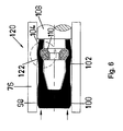
- an alternative embodiment 96 generally including a cover seal 98 having a body 100 and a sleeve 102, the sleeve 102 having a groove 104, a piston 108 includes a groove 110, and a spring 112 is disposed within the grooves 104, as shown in Figures 5A-5D .
- the circumferential groove 110 includes a generally right angled shoulder 114 and the internal groove includes an opposing angled shoulder 116 for orienting the spring 112 with a point of contact between the elliptical spring and the angled shoulder disposed below the endpoint of the major axis to provide locking seal 98 and piston together.
- a latching configuration is shown in Figures 5C-5D .
- FIGS 6 , 6A-6D which is similar to the embodiment 96 except that an elastomer filled spring 122 is utilized.
- Common reference numbers refer to identical or substantial similar structure hereinabove discussed in connection with the embodiment 96 shown in Figures 5 , 5A-5D .
- Figure 7 shows the same type of design but utilizing an O-ring 126 for latching, see Figure 6A for details of the O-ring 126 positioning.
- Figures 8 , 8A-8D show an embodiment 120 of the present invention of a seal 132 for a uni-directional high pressure application which includes a body 134 and an extending cylindrical portion 136 having a circumferential groove 138, a piston 142 includes a bore 144 with a radial internal groove 148 therein all disposed within a housing 152.
- a canted coil spring 164 provides a biasing element and is disposed within the grooves 138, 148.
- a surface 164 in the circumferential groove 138 along with surface 166 disposed in the internal groove 148 orient the spring 162 in order to effect latching or locking between the piston 142 and the seal 132.
- the position of the spring determines the manner in which locking or latching action will occur, as hereinabove described and illustrated in Figures 8A, 8B, 8C, and 8D .
- FIG. 9 there is shown another embodiment 170 in accordance with the present invention which is of a design similar to the embodiment 130 shown in Figure 7 with the exception that a spring loaded O-ring 174 is utilized.
- Other elements of the embodiment 170 indicated by the character references are identical or substantially similar to those hereinabove discussed in connection with the embodiment 130 of Figure 8 .
- FIGS 9A-9B illustrate the function of the surfaces as hereinabove discussed in connection with the earlier presented embodiments.
- Figures 10 and 10A show yet another embodiment 180 similar to that shown in Figures 8 and 9 except that an O-ring 182 is utilized as the latching means between the piston 142 and the seal 132.
- FIGS 11 and 12 show bi-directional low pressure seal apparatus 186, 188 respectively each including a cover seal 192 with a body 194 with a sleeve 196 having an internal groove 198 along with a groove 202 circumferentially formed in a piston 204 and a surfaces 208, 210 for orienting canted coil spring 214 (see Figure 11 ) or an elastomer filled spring 216 (see Figure 12 ) in order to provide both sealing between the sleeve 196 and a housing 220.
- FIGS 11A-11D and 12A-12D showing orientations similar to that hereinbefore discussed or providing either latching or loading between seal 192 and piston 204. Accordingly, a repeat of that description is not repeated for the sake of brevity.
- Figure 13 shows an embodiment 224 having a snap on cover seal 226 for both low and high pressure applications for sealing between a reciprocating piston 228 and housing 230.
- Figures 13 and 13B show a spring loaded O-ring as the locking means
- Figure 12A show the canted coil spring 236 as a locking means
- Figure 12C illustrates an O-ring 238 as a latching means. Operation of the seal apparatus as hereinabove described in connection with the earlier presented embodiments.
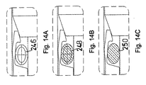
- Figure 14 illustrates seal apparatus 240 including a cover seal 242 and piston 244 along with a spring 246 for providing permanent locking between the piston 244 and the seal 242.
- This particular design is normally used in small diameters due to space requirements and conditions of relatively low pressure to perhaps 100 psi.
- the locking between the piston 244 and the seal 242 is accomplished through the elasticity of the seal which is forced over a notch 248 on the piston 244, a seal 242 is loaded by the O-ring 246 also shown in Figure 13A , a spring loaded O-ring 250.
Landscapes
- Engineering & Computer Science (AREA)
- General Engineering & Computer Science (AREA)
- Mechanical Engineering (AREA)
- Chemical & Material Sciences (AREA)
- Combustion & Propulsion (AREA)
- Sealing Devices (AREA)
- Diaphragms And Bellows (AREA)
Claims (5)
- Dichtungsvorrichtung (130) umfassend
eine Deckeldichtung (132) mit einem Grundkörper (134) und einem sich erstreckenden zylindrischen Abschnitt (136), wobei der zylindrische Abschnitt eine Umfangsnut (138) hat,
einen Kolben (142) mit einer darin vorgesehenen Bohrung (144) mit einer radialen Innennut (148), und
ein Vorspannelement (162), das innerhalb der Innen- (148) und Umfangs-(138) Nuten angeordnet ist,
wobei die Oberflächen (164, 166), die in den Innen- (148) und Umfangs-(138) Nuten angeordnet sind, vorgesehen sind, um das Vorspannelement (162) so auszurichten, dass ein Einrasten oder Verschließen zwischen der Dichtung (132) und dem Kolben (142) bewirkt wird. - Vorrichtung nach Anspruch 1, wobei das Vorspannelement (162) eine elliptische Feder aufweist, die Innennut (148) eine im Allgemeinen rechtwinklige Schulter (40) beinhaltet, die Umfangsnut (138) eine gegenüberliegende abgewinkelte Schulter (44) beinhaltet und die elliptische Feder (36) durch die rechtwinklige Schulter (40) und die abgewinkelte Schulter (44) so ausgerichtet ist, dass der Punktkontakt zwischen der elliptischen Feder (36) und der abgewinkelten Schulter (44) oberhalb eines Endpunkts (54) der Hauptachse (56) der Feder (36) angeordnet ist, so dass ein Verschließen zwischen der Dichtung (132) und dem Kolben (142) ermöglicht wird, oder unterhalb eines Endpunkts (54) der Hauptachse (56) der Feder (36) angeordnet ist, so dass ein Einrasten zwischen der Dichtung (132) und dem Kolben (142) ermöglicht wird.
- Vorrichtung nach Anspruch 2, weiterhin dadurch gekennzeichnet, dass das Vorspannelement (162) eine elliptische Schraubenfeder (36) ist.
- Vorrichtung nach Anspruch 3, weiterhin dadurch gekennzeichnet, dass die elliptische Feder (36) mit einem Elastomer gefüllt ist.
- Vorrichtung nach Anspruch 2, weiterhin dadurch gekennzeichnet, dass das Vorspannelement (162) eine O-Ring (174) ist.
Applications Claiming Priority (3)
| Application Number | Priority Date | Filing Date | Title |
|---|---|---|---|
| US54580804P | 2004-02-18 | 2004-02-18 | |
| US11/058,864 US7210398B2 (en) | 2004-02-18 | 2005-02-16 | Cover seals with latching locking features |
| PCT/US2005/005050 WO2005079456A2 (en) | 2004-02-18 | 2005-02-17 | Cover seals with latching locking features |
Publications (3)
| Publication Number | Publication Date |
|---|---|
| EP1784593A2 EP1784593A2 (de) | 2007-05-16 |
| EP1784593A4 EP1784593A4 (de) | 2011-03-16 |
| EP1784593B1 true EP1784593B1 (de) | 2012-09-26 |
Family
ID=34988865
Family Applications (1)
| Application Number | Title | Priority Date | Filing Date |
|---|---|---|---|
| EP05713726A Expired - Lifetime EP1784593B1 (de) | 2004-02-18 | 2005-02-17 | Deckeldichtung mit rastverriegelungsmerkmalen |
Country Status (3)
| Country | Link |
|---|---|
| US (1) | US7210398B2 (de) |
| EP (1) | EP1784593B1 (de) |
| WO (1) | WO2005079456A2 (de) |
Families Citing this family (35)
| Publication number | Priority date | Publication date | Assignee | Title |
|---|---|---|---|---|
| US7740636B2 (en) * | 2005-04-15 | 2010-06-22 | Abbott Medical Optics Inc. | Multi-action device for inserting an intraocular lens into an eye |
| FI20051240A0 (fi) * | 2005-12-02 | 2005-12-02 | Polarteknik Pmc Oy Ab | Liukupintojen välinen rengastiiviste |
| US7914351B2 (en) * | 2007-04-13 | 2011-03-29 | Bal Seal Engineering | Electrical connectors with improved electrical contact performance |
| WO2009086327A2 (en) * | 2007-12-21 | 2009-07-09 | Bal Seal Engineering | Locking mechanism with quick disassembly means |
| US8096559B2 (en) * | 2008-05-23 | 2012-01-17 | Bal Seal Engineering, Inc. | Rotary seals |
| US20100107829A1 (en) * | 2008-10-30 | 2010-05-06 | Nemcomed, Inc. | Torque limiting driver |
| JP5248414B2 (ja) * | 2009-05-27 | 2013-07-31 | 株式会社東芝 | 開閉器 |
| US10520091B2 (en) | 2009-07-08 | 2019-12-31 | Bal Seal Engineering, Inc. | Double direction seal with locking |
| US8684362B2 (en) | 2009-08-12 | 2014-04-01 | Bal Seal Engineering, Inc. | Cartridge seal assemblies and associated methods |
| US8428724B2 (en) | 2011-03-11 | 2013-04-23 | Greatbatch Ltd. | Low insertion force electrical connector for implantable medical devices |
| US9618483B2 (en) * | 2011-04-25 | 2017-04-11 | Waters Technologies Corporation | Fitting assemblies |
| US10125872B2 (en) | 2011-08-18 | 2018-11-13 | Bal Seal Engineering, Inc. | Reciprocating seal for high pulsating pressure |
| DE102013009131B4 (de) | 2012-06-01 | 2023-12-28 | Bal Seal Engineering, Llc | Gerillte Verbinder mit Haltemechanismen |
| US9829028B2 (en) * | 2012-11-15 | 2017-11-28 | Bal Seal Engineering, Inc. | Connectors with a pin, a housing, and one or more springs |
| US9312630B2 (en) | 2012-12-21 | 2016-04-12 | Bal Seal Engineering, Inc. | Locking connectors and related methods |
| US20150362074A1 (en) * | 2013-02-20 | 2015-12-17 | Nok Corporation | Sealing device |
| US9194497B2 (en) | 2013-09-03 | 2015-11-24 | Bal Seal Engineering, Inc. | Elastic seals with dynamic lips and related methods |
| WO2015125032A1 (en) * | 2014-02-19 | 2015-08-27 | A.T.P. S.P.A. | Dosing piston |
| US10598241B2 (en) | 2014-02-26 | 2020-03-24 | Bal Seal Engineering, Inc. | Multi deflection canted coil springs and related methods |
| US10184564B2 (en) * | 2015-02-02 | 2019-01-22 | Bal Seal Engineering, Inc. | Seal assemblies and related methods |
| US10117366B2 (en) | 2015-12-14 | 2018-10-30 | Bal Seal Engineering, Inc. | Spring energized seals and related methods |
| US11536373B2 (en) | 2016-03-07 | 2022-12-27 | Bal Seal Engineering, Llc | Seal assemblies and related methods |
| US10181668B2 (en) | 2016-06-24 | 2019-01-15 | Bal Seal Engineering, Inc. | Spring contacts and related methods |
| US10460977B2 (en) | 2016-09-29 | 2019-10-29 | Lam Research Corporation | Lift pin holder with spring retention for substrate processing systems |
| EP3312482B1 (de) | 2016-10-24 | 2023-09-13 | Bal Seal Engineering, LLC | Dichtungsanordnungen für extreme temperaturen und zugehörige verfahren |
| US10989305B2 (en) * | 2016-10-31 | 2021-04-27 | Bal Seal Engineering, Llc | Axial and radial floating seals |
| DE18162396T1 (de) | 2017-03-16 | 2018-12-13 | Bal Seal Engineering, Inc. | V-federn, dichtungen mit v-federn und zugehörige verfahren |
| US10604995B2 (en) * | 2017-06-22 | 2020-03-31 | Sejong Pharmatech Co., Ltd. | Sealing door and method of forming channel |
| EP3456428B1 (de) | 2017-08-30 | 2023-08-16 | Bal Seal Engineering, LLC | Federdrahtenden zur ermöglichung des schweissens |
| US11353079B2 (en) | 2017-10-05 | 2022-06-07 | Bal Seal Engineering, Llc | Spring assemblies, applications of spring assemblies, and related methods |
| US11680642B2 (en) | 2018-05-08 | 2023-06-20 | Bal Seal Engineering, Llc | Seal assemblies and related methods |
| US12092160B2 (en) | 2021-09-23 | 2024-09-17 | Bal Seal Engineering Llc | Integrated seal and bearing assembly and related methods |
| US12247663B2 (en) | 2022-11-01 | 2025-03-11 | Bal Seal Engineering, Llc | Lip seals and related methods |
| US11746906B1 (en) | 2022-11-01 | 2023-09-05 | Bal Seal Engineering, Llc | Lip seals and related methods |
| US11940049B1 (en) | 2022-11-01 | 2024-03-26 | Bal Seal Engineering, Llc | Lip seals and related methods |
Family Cites Families (5)
| Publication number | Priority date | Publication date | Assignee | Title |
|---|---|---|---|---|
| CH517041A (de) * | 1971-02-27 | 1971-12-31 | Rieter Ag Maschf | Spulentragvorrichtung mit einer Vorrichtung zum Festhalten und Zentrieren von Hülsen |
| US4678210A (en) * | 1986-08-15 | 1987-07-07 | Peter J. Balsells | Loading and locking mechanism |
| US4804290A (en) | 1986-08-22 | 1989-02-14 | Peter J. Balsells | Latching and sealing device |
| US5161806A (en) * | 1990-12-17 | 1992-11-10 | Peter J. Balsells | Spring-loaded, hollow, elliptical ring seal |
| EP3399598B1 (de) * | 2002-02-15 | 2021-04-28 | Bal Seal Engineering, LLC | Medizinisch implantierbarer elektrischer verbinder mit konstanter leitfähigkeit |
-
2005
- 2005-02-16 US US11/058,864 patent/US7210398B2/en not_active Expired - Lifetime
- 2005-02-17 EP EP05713726A patent/EP1784593B1/de not_active Expired - Lifetime
- 2005-02-17 WO PCT/US2005/005050 patent/WO2005079456A2/en not_active Ceased
Also Published As
| Publication number | Publication date |
|---|---|
| EP1784593A4 (de) | 2011-03-16 |
| WO2005079456A2 (en) | 2005-09-01 |
| US7210398B2 (en) | 2007-05-01 |
| US20050212218A1 (en) | 2005-09-29 |
| WO2005079456A3 (en) | 2007-05-18 |
| EP1784593A2 (de) | 2007-05-16 |
Similar Documents
| Publication | Publication Date | Title |
|---|---|---|
| EP1784593B1 (de) | Deckeldichtung mit rastverriegelungsmerkmalen | |
| US20180119857A1 (en) | Axial and radial floating seals | |
| GB2258276A (en) | Seal ring | |
| US7828300B2 (en) | Sealing device for reciprocating shaft | |
| EP1884691A1 (de) | Lippendichtung | |
| US11767917B2 (en) | Press-in retainer ring | |
| US5456161A (en) | Compact fluid operated cylinder and method | |
| CA2065733C (en) | Annular support for a seal for a tilt piston | |
| US20200393046A1 (en) | Self energized seal | |
| US9746080B2 (en) | High pressure seal assembly for a moveable shaft | |
| MXPA05001560A (es) | Sello de tubo para bujia. | |
| US6588763B1 (en) | Seal arrangement providing a seal between a bore and a rod moveable in the bore | |
| US6431553B1 (en) | Radially pressure balanced floating seal system | |
| US11732801B2 (en) | Self-contained low load narrow groove seal | |
| WO2018180307A1 (ja) | シール材の配置構造 | |
| JP4853633B2 (ja) | 密封装置 | |
| EP1950473B1 (de) | Eingeschlossene vorrichtung zur kohlendioxidgasversiegelung | |
| US4227705A (en) | Semicircular plug for preventing leakage of oil in a cylinder head of an overhead cam shaft engine | |
| JP5066787B2 (ja) | 密封構造 | |
| JP6660759B2 (ja) | 密封装置 | |
| JP2581284Y2 (ja) | キャップシール | |
| JP3965785B2 (ja) | 密封装置 | |
| JP4143786B2 (ja) | 密封装置 | |
| JP2555598Y2 (ja) | 密封装置 | |
| JPH11141688A (ja) | 密封装置 |
Legal Events
| Date | Code | Title | Description |
|---|---|---|---|
| PUAI | Public reference made under article 153(3) epc to a published international application that has entered the european phase |
Free format text: ORIGINAL CODE: 0009012 |
|
| AK | Designated contracting states |
Kind code of ref document: A2 Designated state(s): AT BE BG CH CY CZ DE DK EE ES FI FR GB GR HU IE IS IT LI LT LU MC NL PL PT RO SE SI SK TR |
|
| AX | Request for extension of the european patent |
Extension state: AL BA HR LV MK YU |
|
| DAX | Request for extension of the european patent (deleted) | ||
| RBV | Designated contracting states (corrected) |
Designated state(s): DE FR GB |
|
| R17D | Deferred search report published (corrected) |
Effective date: 20070518 |
|
| RIC1 | Information provided on ipc code assigned before grant |
Ipc: F16J 9/12 20060101ALI20070717BHEP Ipc: F02F 5/00 20060101AFI20070717BHEP |
|
| 17P | Request for examination filed |
Effective date: 20071119 |
|
| RBV | Designated contracting states (corrected) |
Designated state(s): DE FR GB |
|
| A4 | Supplementary search report drawn up and despatched |
Effective date: 20110211 |
|
| RIC1 | Information provided on ipc code assigned before grant |
Ipc: F16J 1/00 20060101ALI20110207BHEP Ipc: F16J 9/12 20060101ALI20110207BHEP Ipc: F02F 5/00 20060101AFI20070717BHEP |
|
| 17Q | First examination report despatched |
Effective date: 20110420 |
|
| REG | Reference to a national code |
Ref country code: DE Ref legal event code: R079 Ref document number: 602005036270 Country of ref document: DE Free format text: PREVIOUS MAIN CLASS: F16J0015000000 Ipc: F02F0005000000 |
|
| RIC1 | Information provided on ipc code assigned before grant |
Ipc: F16J 1/00 20060101ALI20120306BHEP Ipc: F16J 9/12 20060101ALI20120306BHEP Ipc: F02F 5/00 20060101AFI20120306BHEP Ipc: F16J 15/32 20060101ALI20120306BHEP Ipc: F16J 15/56 20060101ALI20120306BHEP |
|
| GRAP | Despatch of communication of intention to grant a patent |
Free format text: ORIGINAL CODE: EPIDOSNIGR1 |
|
| GRAS | Grant fee paid |
Free format text: ORIGINAL CODE: EPIDOSNIGR3 |
|
| GRAA | (expected) grant |
Free format text: ORIGINAL CODE: 0009210 |
|
| AK | Designated contracting states |
Kind code of ref document: B1 Designated state(s): DE FR GB |
|
| REG | Reference to a national code |
Ref country code: GB Ref legal event code: FG4D |
|
| REG | Reference to a national code |
Ref country code: DE Ref legal event code: R096 Ref document number: 602005036270 Country of ref document: DE Effective date: 20121122 |
|
| PLBE | No opposition filed within time limit |
Free format text: ORIGINAL CODE: 0009261 |
|
| STAA | Information on the status of an ep patent application or granted ep patent |
Free format text: STATUS: NO OPPOSITION FILED WITHIN TIME LIMIT |
|
| 26N | No opposition filed |
Effective date: 20130627 |
|
| REG | Reference to a national code |
Ref country code: DE Ref legal event code: R097 Ref document number: 602005036270 Country of ref document: DE Effective date: 20130627 |
|
| REG | Reference to a national code |
Ref country code: FR Ref legal event code: PLFP Year of fee payment: 12 |
|
| REG | Reference to a national code |
Ref country code: FR Ref legal event code: PLFP Year of fee payment: 13 |
|
| REG | Reference to a national code |
Ref country code: FR Ref legal event code: PLFP Year of fee payment: 14 |
|
| REG | Reference to a national code |
Ref country code: DE Ref legal event code: R081 Ref document number: 602005036270 Country of ref document: DE Owner name: BAL SEAL ENGINEERING, LLC, FOOTHILL RANCH, US Free format text: FORMER OWNER: BAL SEAL ENGINEERING CO., INC., LAKE FOREST, CALIF., US |
|
| PGFP | Annual fee paid to national office [announced via postgrant information from national office to epo] |
Ref country code: DE Payment date: 20240228 Year of fee payment: 20 Ref country code: GB Payment date: 20240227 Year of fee payment: 20 |
|
| PGFP | Annual fee paid to national office [announced via postgrant information from national office to epo] |
Ref country code: FR Payment date: 20240226 Year of fee payment: 20 |
|
| REG | Reference to a national code |
Ref country code: DE Ref legal event code: R071 Ref document number: 602005036270 Country of ref document: DE |
|
| REG | Reference to a national code |
Ref country code: GB Ref legal event code: PE20 Expiry date: 20250216 |
|
| PG25 | Lapsed in a contracting state [announced via postgrant information from national office to epo] |
Ref country code: GB Free format text: LAPSE BECAUSE OF EXPIRATION OF PROTECTION Effective date: 20250216 |