EP1783584A2 - Kühlvorrichtung für Flachbildschirm - Google Patents
Kühlvorrichtung für Flachbildschirm Download PDFInfo
- Publication number
- EP1783584A2 EP1783584A2 EP06254525A EP06254525A EP1783584A2 EP 1783584 A2 EP1783584 A2 EP 1783584A2 EP 06254525 A EP06254525 A EP 06254525A EP 06254525 A EP06254525 A EP 06254525A EP 1783584 A2 EP1783584 A2 EP 1783584A2
- Authority
- EP
- European Patent Office
- Prior art keywords
- flat display
- cooling apparatus
- fan
- display device
- back cover
- Prior art date
- Legal status (The legal status is an assumption and is not a legal conclusion. Google has not performed a legal analysis and makes no representation as to the accuracy of the status listed.)
- Withdrawn
Links
Images


Classifications
-
- H—ELECTRICITY
- H05—ELECTRIC TECHNIQUES NOT OTHERWISE PROVIDED FOR
- H05K—PRINTED CIRCUITS; CASINGS OR CONSTRUCTIONAL DETAILS OF ELECTRIC APPARATUS; MANUFACTURE OF ASSEMBLAGES OF ELECTRICAL COMPONENTS
- H05K7/00—Constructional details common to different types of electric apparatus
- H05K7/20—Modifications to facilitate cooling, ventilating, or heating
- H05K7/20954—Modifications to facilitate cooling, ventilating, or heating for display panels
- H05K7/20972—Forced ventilation, e.g. on heat dissipaters coupled to components
-
- G—PHYSICS
- G06—COMPUTING OR CALCULATING; COUNTING
- G06F—ELECTRIC DIGITAL DATA PROCESSING
- G06F1/00—Details not covered by groups G06F3/00 - G06F13/00 and G06F21/00
- G06F1/16—Constructional details or arrangements
- G06F1/1601—Constructional details related to the housing of computer displays, e.g. of CRT monitors, of flat displays
-
- G—PHYSICS
- G06—COMPUTING OR CALCULATING; COUNTING
- G06F—ELECTRIC DIGITAL DATA PROCESSING
- G06F1/00—Details not covered by groups G06F3/00 - G06F13/00 and G06F21/00
- G06F1/16—Constructional details or arrangements
- G06F1/20—Cooling means
-
- Y—GENERAL TAGGING OF NEW TECHNOLOGICAL DEVELOPMENTS; GENERAL TAGGING OF CROSS-SECTIONAL TECHNOLOGIES SPANNING OVER SEVERAL SECTIONS OF THE IPC; TECHNICAL SUBJECTS COVERED BY FORMER USPC CROSS-REFERENCE ART COLLECTIONS [XRACs] AND DIGESTS
- Y10—TECHNICAL SUBJECTS COVERED BY FORMER USPC
- Y10S—TECHNICAL SUBJECTS COVERED BY FORMER USPC CROSS-REFERENCE ART COLLECTIONS [XRACs] AND DIGESTS
- Y10S345/00—Computer graphics processing and selective visual display systems
- Y10S345/905—Display device with housing structure
Definitions
- the present invention relates to a flat display device.
- Embodiments of the present invention relate to a cooling apparatus for a flat display device, which can be operated with a low noise while quickly dissipating internal heat to an external side.
- a flat display uses a driving circuit arranged in a matrix pattern to differently excite pixels and thus realize an image.
- flat display devices have been widely used since they are advantageous in that they take up a relatively small amount of space.
- a variety of flat display modules such as a liquid crystal display (LCD), a field emission display (FED), a plasma display panel (PDP), and an electro-luminescence (EL) have been applied to flat display devices.
- the display device since the image is realized by electric discharge of discharge gas, a large amount of heat is generated. Therefore, if the large amount of heat is not quickly dissipated, the display device may malfunction. Needless to say, in the case of other types of flat display devices, the heat dissipation performance is a very important fact in determining the quality thereof.
- a heat sink is attached on a rear surface of a specific component generating a large amount of heat to cool the specific component. Furthermore, in order to generally dissipate the heat, a plurality of holes is formed on a cover of the flat display device so that cool air can pass through the holes.
- the heat is not effectively dissipated to the external side. Therefore, the flat display device cannot be stably operated. That is, the internal temperature of the flat display device increases to the detriment of the performance of the flat display device.
- an axial fan is installed on a rear center portion of a back cover in a direction perpendicular to a direction where the display device is formed.
- the axial fan forcedly exhausts the internal high temperature air of the flat display device to the external side through a rear side of the display device.
- the heat collected in the display device can be effectively discharged to the external side, excessive noise is generated during the operation of the axial fan.
- a gap of ten or more centimeters must be provided between the rear surface of the display device and the wall so that the air can be exhausted.
- an overall thickness of the flat display device increases.
- the back cover Furthermore, a plurality of holes through which the air is exhausted and introduced are formed on the back cover.
- the holes of the back cover deteriorate the strength of the back cover. Therefore, the back cover must be of sufficient thickness In which case, the manufacturing cost increases.
- embodiments of the present invention are directed to cooling apparatus for a flat display device that substantially obviates one or more problems due to limitations and disadvantages of the prior art.
- Embodiments of the present invention seek to provide a cooling apparatus for a flat display device, which is designed to make the flat display device slimmer and effectively dissipate internal heat of the flat display device.
- Embodiments of the present invention seek to provide a cooling apparatus for a flat display device, which can minimize noise and be manufactured with low costs.
- Embodiments of the present invention seek to provide a cooling apparatus for a flat display device, which can minimize noise and improve heat dissipation efficiency by allowing internal air of the flat display device to be exhausted by natural convection.
- Embodiments of the present invention seek to provide a cooling apparatus for a flat display device, which can improve a degree of installation free of the display device by improving an airflow direction in the flat display device.
- Embodiments of the present invention seek to provide a cooling apparatus for a flat display device, which can enhance the strength of a back cover by improving the location and structure of holes formed on the back cover.
- Embodiments of the present invention seek to provide a cooling apparatus for a flat display device, which can improve an operation reliability of the flat display device.
- Embodiments of the present invention seek to provide a cooling apparatus for a flat display device, which can provide high heat dissipation efficiency even for a large-sized flat display device.
- FIG. 1 is a perspective view of a flat display device having a cooling apparatus according to an embodiment of the present invention
- FIG. 2 is a partially broken perspective view of the flat panel display of FIG. 1;
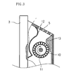
- FIG. 3 is a sectional view taken along line I-I' ;
- FIG. 4 is a perspective view of the flat display device of FIG. 2, in which the impeller and the motor are omitted;
- FIG. 5 is a sectional view taken along line II-II' ;
- FIG. 6 is a rear view of the flat display device of FIG. 1;
- FIG. 7 is a perspective view of a flat display device having an cooling apparatus according to another embodiment of the present invention.
- FIG. 8 is a partly broken perspective view of the flat display device of FIG. 7;
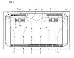
- FIG. 9 is a rear view of the flat display device of FIG. 7;
- FIG. 10 is a perspective view of a flat display device having a cooling apparatus according to another embodiment of the present invention.
- FIG. 11 is a rear view of the flat display device of FIG. 10;
- FIG. 12 is a rear view of a flat display device having a cooling apparatus according to another embodiment of the present invention.
- FIG. 13 is a rear view of a flat display device having a cooling apparatus according to another embodiment of the present invention.
- a flat display device 1 of this embodiment includes a flat display module 2, a front cover 3 for supporting and protecting a front portion of the flat display module 2, and a back cover 4 for supporting and protecting a rear portion of the flat display module 2.
- An air outlet 5 through which internal hot air of the flat display device 1 is exhausted, is formed on an upper peripheral of the back cover 4.
- the air outlet 5 has a plurality of slits.
- the slits are arranged not to deteriorate strength of the back cover 4. That is, the air outlet 5 means a portion provided in the back cover 4, of which the inner area has the slits arranged in a type of aggregation.
- the flat display module 2 may be selected from the group consisting of an LCD, an FED, a PDP, and an EL. In some embodiments the flat display module 2 is provided with the PDP generating high temperature heat.
- the front and back covers 3 and 4 define a space for receiving the flat display module 2 and protect components disposed in the space.
- the front and back covers 3 and 4 are independent parts that are assembled with each other.
- the present invention is not limited to this case.
- the front and rear covers 3 and 4 may be integrally formed as a single body to protect the front and rear portions of the display device.
- the flat display device 1 When the flat display device 1 operates, a large amount of heat is generated in the flat display module 2. At this point, the hot air generated from the heat generating component disposed on the rear surface of the flat display module 2 is cooled by the incoming air. Then, the hot air flows upward and is then exhausted through the air outlet 5. This is the natural convection for exhausting the hot air out of the flat display device, thereby improving the cooling efficiency.
- outer air is introduced through an overall area of the bottom portion of the flat display device 1 and exhausted via an overall area of the rear portion of the display device.
- the air outlet 5 is provided on an inclined portion of the back cover frame so that the hot air can be exhausted upward and thus the hot air can more effectively flow.
- the heat generated from the front portion of the display module 2 can be quickly dissipated by the natural convention of the outer air.
- a cross-flow fan 7 is installed in an inner-upper portion of the flat display device 1 in a longitudinal direction of the flat display device 1. Proximal to the cross-flow fan 7, the top surface of the back cover 4 provides a gap through which the internal hot air is exhausted to the external side. Since the hot air can be exhausted through the top surface of the back cover 4, the air exhaust can be more effectively realized to reduce airflow resistance and airflow noise, thereby enhancing the heat dissipation efficiency of the flat display device.
- the cross-flow fan 7 includes an impeller (10 of FIG. 3) disposed in the longitudinal direction of the back cover 4 and a circular plate for dividing the impeller 10 by a predetermined interval along the longitudinal direction of the impeller 10 and enhancing strength of the impeller.
- the cross-flow fan 7 further includes a driving shaft 15 connected to a motor 14. A rotational force from the motor 14 is transferred to the cross-flow fan via the driving shaft 15.
- the impeller 10 is disposed in a housing 18 to guide the airflow when the impeller 10 rotates.
- the housing 18 includes a scroll 12 disposed in front of the impeller 10 and spaced apart from the impeller 10 and a stabilizer 13 disposed in rear of the impeller 10 and spaced apart from the impeller 10.
- the impeller 10 rotates clockwise in the drawing.
- the cross-flow fan 7 extends fully relative to the overall longitudinal length of the top surface of the back cover 4, a relatively large amount of air can be exhausted. Needless to say, when there is no need to dispose the cross-flow fan 7 relative to the overall longitudinal length, i.e. in cases where the screen size of the display device is small, the lengths of the air outlet 5 and the cross-flow fan 7 may be reduced.
- the air exhaust area increased as compared to that of the prior art, the airflow resistance and airflow noise can be reduced. Furthermore, since the hot air is exhausted through the top surface of the back cover 4, there is no need to provide a gap between a wall on which the display device is installed and a rear surface of the back cover 4. Therefore, the flat panel display device can be closely installed on the wall, thereby taking up a relatively small amount of space.
- a rectangular airflow channel 20 is defined between the stabilizer 13 and the scroll 12.
- the cross-flow fan 7 is installed in the air flow channel 20.
- a cross-sectional area of the airflow channel 20 provides an effective exhausting area "S" for exhausting the air by the cross-flow fan 7.
- the effective exhausting area "S" is almost identical to an area of the top surface of the back cover 4, the internal hot air of the flat display device can be quickly and effectively exhausted to the external side. That is, as the effective exhaust area increases, the internal hot air can be more quickly exhausted and the noise can be further reduced, thereby further improving the heat dissipation efficiency.
- the effective exhaust area "S" formed on the top surface of the back cover 4 can further increase. Therefore, even though an amount of heat generated in the flat display device having the large-sized screen increases, the heat can be effectively dissipated only if the size of the effective exhaustive area "S" is increased. Furthermore, since the cross-flow fan 7 is installed along the overall longitudinal length of the display device without interfering other components, the heat dissipation efficiency can be further improved.
- the effective exhaust area "S" formed on the top surface of the back cover 4 is defined by a rectangular area defined by parallel longitudinal sides and parallel lateral sides of the display device. Namely, the effective exhaust area “S” is defined by a first edge provided in a lengthwise direction of the flat display device and a second edge provided in a perpendicular direction, namely widthwise direction of the flat display device to the lengthwise direction of the flat display device. The first edge and second edge each have a parallel line forming a shape of a rectangle. That is, since the effective exhaust area "S" is almost identical to that of the top surface of the back cover 4, the heat generated in the display device can be sufficiently dissipated to the external side through the effective exhaust area "S".
- the back cover 4 is further provided with a lower air inlet 16 and a rear air inlet 17.
- the lower air inlet 16 is formed on an inclined portion of the lower peripheral of the back cover 4 to introduce external cool air into the flat display device.
- the cool air introduced through the lower air inlet compensates for the hot air exhausted through the air outlet 5. That is, the cool air introduce compensates for a reduced pressure generated by the natural convection and a reduced pressure generated by the air exhausted through the air outlet 5.
- the cool air introduced through the lower air inlet 16 cools the components provided on the rear surface of the flat display module 2 and is then exhausted through the air outlet 5 via the cross-flow fan 7.
- the lower air inlet 16 is formed along the overall longitudinal length of the lower peripheral of the back cover 4 so that the components can be uniformly cooled. Arrows in the drawing indicates the airflow direction.
- the cross-flow fan 7 is formed along the overall longitudinal length of the top surface of the back cover 4 and the effective exhaust area "S" is formed throughout the overall area of the top surface of the back cover 4. Therefore, the cool air introduced through the lower air inlet 16 flows upward, in the course of which the components are cooled, and is then exhausted through the air outlet. If the length of the cross-flow fan 7 is reduced, the heat dissipation effect at the corner sides of the flat display device may be reduced. Nevertheless, since the effective exhaust area "S" is large enough, the heat dissipation efficiency can be still improved.
- Some of the components generate high temperature heat (i.e. a power unit) and some of the components (i.e. tape carrier package chip (TCP)) require a low temperature condition.
- a power unit i.e. a power unit
- TCP tape carrier package chip
- the components which require thermal stability are disposed close to the lower air inlet 16 so that they can be quickly cooled by the cool air introduced.
- the components generating a large amount of heat are disposed close to the cross-flow fan 7 so that the heat generated by these components can be quickly dissipated without affecting on other circuits.
- the rear air inlet 17 is provided for the components that cannot change their installed location. That is, the rear air inlet 17 is formed on a portion of the back cover 4 corresponding to a specific portion of the flat display module 2 where the heat generation components are disposed. Therefore, the heat generation components disposed corresponding to the rear air inlet 17 can be quickly cooled by the cool air introduced through the rear air inlet 17.
- the air inlet 17 is not an indispensable component, therefore, if the installing location of the heat generation components can be changed, the rear air intake opening components may be omitted. That is, the heat generation components may be adjusted in their installing location to be closer to the cross-flow fan 7 or the lower air inlet 16.
- the cross-flow fan can be disposed along the overall length of the peripheral of the back cover 4, the internal hot air of the back cover can be quickly exhausted, thereby improving the heat dissipation efficiency and operational reliability of the flat display device.
- a flat display device of this embodiment includes a flat display module 32, a front cover 33 for supporting and protecting a front portion of the flat display module 32, and a back cover 34 for supporting and protecting a rear portion of the flat display module 32.
- Left and right air outlets 51 and 52 through which internal hot air of the flat display device is exhausted are formed on a top surface of the back cover 34.
- the air outlets 51 and 52 are formed on the right and left sides of the top surface of the back cover 34, the cooling efficiency for both sides of the flat display device can be more improved.
- FIG. 8 is a partly broken perspective view of the flat display device of FIG. 7, in which an upper potion of the flat display device is broken away.
- a left sirocco fan 41 is disposed inside the back cover 34 and aligned with the left air outlet 51 and a right sirocco fan 46 is disposed inside the back cover 34 and aligned with the right air outlet 52.
- the internal hot air is exhausted through the left and right air outlets 51 and 52 by the left and right sirocco fans 41 and 46.
- left and right sirocco fans 41 and 46 are identical in a structure, only the left sirocco fan 41 will be described hereinafter.
- the left sirocco fan 41 is a bi-directional air intake fan.
- the left sirocco fan 41 includes a housing 43 opposite ends of which are opened and an impeller 42 disposed in the housing 43.
- a motor 44 is disposed on a middle portion of the impeller 42.
- the air introduced through the opposite ends of the housing 43 is directed upward and exhausted through a right exhaust opening 45 having a rectangular effective exhaust area "S". Then, the air is exhausted to the external side through the right air outlet 51.
- an airflow guide 50 is disposed between the sirocco fans 41 and 46.
- the airflow guide 50 is curved downward from the upper sides of the adjacent ends of the sirocco fans 41 and 46.
- the airflow guide functions to guide the cool air introduced into the display device to the sirocco fans as well as prevent the backflow of the air exhausted through the exhaust openings 45 and 47.
- the cool air introduced through the lower air inlet cools the components provided on the rear surface of the flat display module 32 and is then introduced into the sirocco fans 41 and 46 by being guided by the airflow guide 50.
- the airflow guide 50 includes first through fourth airflow guide portions 61 through 64. Each airflow guide portion is curved downward from a top of the housing, thereby effectively guiding the air to the opposite ends of the housing 43.
- the air introduced into the sirocco fans 41 and 46 through the opposite ends is exhausted to the external side through the exhaust opening 45 and the air outlet 51 by the impellers 42.
- the effective exhaust area S is defined along the longitudinal length of the flat display device, the airflow resistance and the airflow noise can be reduced.
- rear air intake openings identical to the rear air intake opening 17 of FIG. 6 may be further formed on the back cover 4.
- sirocco fans are provided, the present invention is not limited to this.
- the number of sirocco fans may vary according to the size of the flat display device.
- the overall area of the top surface of the back cover may be the effective air exhaust area, the heat dissipation efficiency can be further improved.
- the sirocco fan is the bi-directional air intake fan
- the present invention is not limited to this. That is, the sirocco fan may be a one-way air intake fan where the motor is installed on one end of the impeller to direct the air in a predetermined direction.
- two or more sirocco fans are arranged in series to increase the hot air exhaust space.
- the airflow resistance and airflow noise can be also reduced.
- the shape of the effective exhaust area may vary according to a shape of the outlet of the fan.
- the effective exhaust area may be formed in a trapezoidal shape.
- a cross-flow fan 7 of this embodiment is different from that of FIG. 2. That is, the cross-flow fan 7 of this embodiment includes a motor 14 installed on a middle portion. Driving shafts 151 and 152 extend from opposite ends of the motor 14 and are connected to an impeller unit 10.
- the impeller unit 10 includes left and right impellers 101 and 102. Therefore, the vibration or unstable operation, which may be caused when the impeller unit 10 is formed in a long single impeller, can be prevented.
- the left and right impellers 101 and 102 are connected to the single motor 14 by the left and right driving shafts 151 and 152, respectively. Therefore, when the motor 14 operates, the left and right impellers 101 and 102 can simultaneously rotate.
- the impeller unit 10 is divided into the left and right impellers 101 and 102 each having a relatively short length, it can be stably operated without generating vibration and noise. That is, even when the vibration of the motor 14 is transferred to the impellers 101 and 102, the vibration is not excessively magnified and thus the generation of the vibration and noise can be relatively reduced, thereby improving the operational reliability of the cross-flow fan 7.
- the left and right impellers 101 and 102 can be supported by independent supporting structures, the structural reliability of the cross-flow fan 7 can be improved. That is, when the impeller unit 10 is a single long impeller, one end of the impeller is connected to the driving shaft of the motor while the other is supported on an extra supporting structure. In this case, the supporting structure of the impeller unit is unstable to prevent the vibration of the fan.
- the impeller unit 10 of this embodiment is divided into the left and right short impellers with same length and the left and right short impellers are supported by the independent supporting structures, the overall operation of the cooling apparatus can be stably realized. Even in this case, since only one motor is used, the cost does not increase.
- the impellers 101 and 102 can extend to reach left and right inner ends of the back cover 4. That is, when the impeller unit is the single impeller one end of which is connected to the motor, the impeller cannot extend to reach one inner end of the back case due to the motor.
- the motor since the motor is disposed between the impellers 101 and 102, the impellers 101 and 102 can extend to reach left and right inner ends of the back cover 4. Therefore, the components disposed at both inner side ends of the display device can be effectively cooled.
- a single scroll 12 is provided for both the left and right impellers 101 and 102 and a single stabilizer 13 is also provided for both the left and right impellers 101 and 102.
- the present invention is not limited to this case.
- separated scrolls may be provided for the left and right impellers 101 and 102, respectively.
- separated stabilizers may be provided for the left and right impellers 101 and 102, respectively.
- the left and right impellers 101 and 102 may be different in a structure from each other.
- the cooling operation of this embodiment is substantially identical to that of FIG. 6 except that the left and right impellers 101 and 102 stably rotate by the motor 14 disposed therebetween.
- a cross-flow fan of this embodiment includes first and second cross-flow fans 71 and 72 and first and second motors 73 and 74 rotating respectively the first and second cross-flow fans 71 and 72.
- the first and second motors 73 and 74 are respectively installed on outer ends of the respective first and second cross-flow fans 71 and 72.
- This embodiment may be applied for a large-sized flat display device. That is, when the size of the flat display device increases the length of the cross-flow fan also increases. In this case, the long cross-flow fan is not effectively operated by a single motor. Therefore, the cross-flow fan is divided into two fans operated by independent motors, respectively.
- the flat display device of the embodiment shown in Fig. 13 is substantially identical to those of FIGs. 10 and 12 except for the structure of the cross-flow fan. Therefore, only the different portion will be described hereinafter.
- a cross-flow fan of this embodiment includes first and second cross-flow fans 81 and 82 and first and second motors 83 and 84 rotating respectively the first and second cross-flow fans 81 and 82.
- the first and second motors 83 and 84 are respectively installed on inner ends of the respective first and second cross-flow fans 81 and 82.
- the cross-flow fan only the impeller may be separated into two impellers or overall body including the scroll and stabilizer may be separated into two sections.
- This embodiment may be applied for a large-sized flat display device. That is, when the size of the flat display device increases, the length of the cross-flow fan also increases. In this case, the long cross-flow fan is not effectively operated by a single motor. Therefore, the cross-flow fan is divided into two fans operated by independent motors, respectively. Furthermore, this embodiment could be adapted for cooling the corner portion of the flat display device, differently from the fourth embodiment.
- the flat display device can be designed to be slimmer while providing a sufficient heat dissipation effect.
- the air exhaust outlet is formed in a shape similar to a cross section of the flat display device, the structure is simplified and the airflow noise can be minimized.
- the internal hot air of the flat display device can be exhausted by a reduced pressure generated by the fan as well as by the natural convection, the air circulation can be effectively realized in the display device.
- the cooling apparatus can improve a degree of installation free of the display device by improving an airflow direction in the flat display device.
- the cooling apparatus of embodiments of the present invention can enhance strength of a back cover by improving location and structure of holes formed on the back cover.
- the cooling apparatus can minimize noise and improve heat dissipation efficiency by allowing internal air of the flat display device to be exhausted by natural convection.
- the fan can be stably supported, the operational reliability of the fan can be improved and the vibration generated during the rotation of the fan can be reduced.
- the rotational speed of the cross-flow fans can be controlled in response to the internal thermal load of the flat display device, thereby properly cooling the flat display device.
Landscapes
- Engineering & Computer Science (AREA)
- Theoretical Computer Science (AREA)
- General Engineering & Computer Science (AREA)
- Physics & Mathematics (AREA)
- Human Computer Interaction (AREA)
- General Physics & Mathematics (AREA)
- Computer Hardware Design (AREA)
- Thermal Sciences (AREA)
- Microelectronics & Electronic Packaging (AREA)
- Devices For Indicating Variable Information By Combining Individual Elements (AREA)
- Cooling Or The Like Of Electrical Apparatus (AREA)
Applications Claiming Priority (2)
| Application Number | Priority Date | Filing Date | Title |
|---|---|---|---|
| KR1020050105172A KR100747848B1 (ko) | 2005-11-04 | 2005-11-04 | 평면 디스플레이 기기의 냉각 장치 |
| KR1020050105174A KR100731382B1 (ko) | 2005-11-04 | 2005-11-04 | 평면 디스플레이 기기의 냉각 장치 |
Publications (2)
| Publication Number | Publication Date |
|---|---|
| EP1783584A2 true EP1783584A2 (de) | 2007-05-09 |
| EP1783584A3 EP1783584A3 (de) | 2009-12-02 |
Family
ID=37682781
Family Applications (1)
| Application Number | Title | Priority Date | Filing Date |
|---|---|---|---|
| EP06254525A Withdrawn EP1783584A3 (de) | 2005-11-04 | 2006-08-30 | Kühlvorrichtung für Flachbildschirm |
Country Status (2)
| Country | Link |
|---|---|
| US (1) | US7463487B2 (de) |
| EP (1) | EP1783584A3 (de) |
Families Citing this family (58)
| Publication number | Priority date | Publication date | Assignee | Title |
|---|---|---|---|---|
| JP2006152921A (ja) * | 2004-11-29 | 2006-06-15 | Sony Corp | 冷却用送風ファン及び映像表示装置 |
| KR100747849B1 (ko) * | 2005-11-04 | 2007-08-08 | 엘지전자 주식회사 | 평면 디스플레이 기기 및 평면 디스플레이 기기의 냉각장치 |
| KR100747820B1 (ko) * | 2005-11-04 | 2007-08-08 | 엘지전자 주식회사 | 평면 디스플레이 기기의 냉각 장치 |
| KR100772247B1 (ko) * | 2005-11-04 | 2007-11-01 | 엘지전자 주식회사 | 평면 디스플레이 기기 및 평면 디스플레이 기기의 냉각장치 |
| US7463487B2 (en) | 2005-11-04 | 2008-12-09 | Lg Electronics Inc. | Cooling apparatus for flat display device |
| US7969719B2 (en) * | 2006-01-04 | 2011-06-28 | Westinghouse Digital, Llc | Back panel for video display device |
| KR101435801B1 (ko) * | 2007-08-30 | 2014-08-29 | 엘지전자 주식회사 | 디스플레이 장치 |
| US7892306B2 (en) * | 2007-09-26 | 2011-02-22 | Propulsive Wing, LLC | Multi-use personal ventilation/filtration system |
| US8333816B2 (en) * | 2007-09-26 | 2012-12-18 | Propulsive Wing Llc | Multi-use personal ventilation/filtration system |
| US8854595B2 (en) | 2008-03-03 | 2014-10-07 | Manufacturing Resources International, Inc. | Constricted convection cooling system for an electronic display |
| US12185512B2 (en) | 2007-11-16 | 2024-12-31 | Manufacturing Resources International, Inc. | Electronic display assembly with thermal management |
| US8654302B2 (en) | 2008-03-03 | 2014-02-18 | Manufacturing Resources International, Inc. | Heat exchanger for an electronic display |
| US8497972B2 (en) | 2009-11-13 | 2013-07-30 | Manufacturing Resources International, Inc. | Thermal plate with optional cooling loop in electronic display |
| US8693185B2 (en) | 2008-03-26 | 2014-04-08 | Manufacturing Resources International, Inc. | System and method for maintaining a consistent temperature gradient across an electronic display |
| EP2289236B1 (de) * | 2008-05-07 | 2017-03-29 | Civiq Smartscapes | Videoanzeigesystem |
| WO2010013307A1 (ja) * | 2008-07-28 | 2010-02-04 | Necディスプレイソリューションズ株式会社 | 表示装置 |
| EP2314074A4 (de) * | 2008-07-29 | 2013-06-26 | Thomson Licensing | Anzeigecharakterisierung mit filtrierung |
| US10827656B2 (en) | 2008-12-18 | 2020-11-03 | Manufacturing Resources International, Inc. | System for cooling an electronic image assembly with circulating gas and ambient gas |
| US8749749B2 (en) | 2008-12-18 | 2014-06-10 | Manufacturing Resources International, Inc. | System for cooling an electronic image assembly with manifolds and ambient gas |
| EP2509304A1 (de) * | 2009-12-03 | 2012-10-10 | Panasonic Corporation | Strahlungseinheit für eine elektronische vorrichtung und elektronische vorrichtung damit |
| KR101712100B1 (ko) * | 2010-01-12 | 2017-03-03 | 삼성전자 주식회사 | 냉각장치 및 이를 구비하는 표시장치 |
| US8081267B2 (en) | 2010-03-08 | 2011-12-20 | Peerless Industries, Inc. | Display enclosure |
| US8102483B2 (en) | 2010-03-08 | 2012-01-24 | Peerless Industries, Inc. | Display enclosure |
| USD669075S1 (en) | 2011-10-27 | 2012-10-16 | Ciil Technologies, Llc | Display enclosure for use with audio/visual devices or the like |
| US8714665B2 (en) | 2012-01-20 | 2014-05-06 | Ciil Technologies Llc | Enclosed television with improved enclosure sealing arrangement |
| US9078345B2 (en) | 2012-01-20 | 2015-07-07 | Ciil Technologies, Llc | Enclosed television with improved cable cover sealing mechanism |
| US10660245B2 (en) | 2012-10-16 | 2020-05-19 | Manufacturing Resources International, Inc. | Back pan cooling assembly for electronic display |
| US10524384B2 (en) | 2013-03-15 | 2019-12-31 | Manufacturing Resources International, Inc. | Cooling assembly for an electronic display |
| WO2014149773A1 (en) | 2013-03-15 | 2014-09-25 | Manufacturing Resources International, Inc. | Heat exchange assembly for an electronic display |
| US9470924B2 (en) | 2013-07-08 | 2016-10-18 | Manufacturing Resources International, Inc. | Figure eight closed loop cooling system for electronic display |
| CA2942321C (en) | 2014-03-11 | 2022-06-14 | Manufacturing Resources International, Inc. | Hybrid rear cover and mounting bracket for electronic display |
| AU2015253128B2 (en) | 2014-04-30 | 2017-12-14 | Manufacturing Resources International, Inc. | Back to back electronic display assembly |
| US9723765B2 (en) | 2015-02-17 | 2017-08-01 | Manufacturing Resources International, Inc. | Perimeter ventilation system for electronic display |
| JP6082780B2 (ja) * | 2015-07-03 | 2017-02-15 | 上銀科技股▲分▼有限公司 | 多軸コントローラに適用する放熱方法 |
| US20170130948A1 (en) * | 2015-11-05 | 2017-05-11 | Litemax Electronics Inc. | High -brightness panel heat-dissipating apparatus |
| AU2017228430B2 (en) | 2016-03-04 | 2019-11-21 | Manufacturing Resources International, Inc. | Cooling system for double sided display assembly |
| KR102262912B1 (ko) | 2017-04-27 | 2021-06-10 | 매뉴팩처링 리소시스 인터내셔널 인코포레이티드 | 표시장치의 휘어짐을 방지하기 위한 시스템 및 방법 |
| US10485113B2 (en) | 2017-04-27 | 2019-11-19 | Manufacturing Resources International, Inc. | Field serviceable and replaceable display |
| US10559965B2 (en) | 2017-09-21 | 2020-02-11 | Manufacturing Resources International, Inc. | Display assembly having multiple charging ports |
| US10602626B2 (en) | 2018-07-30 | 2020-03-24 | Manufacturing Resources International, Inc. | Housing assembly for an integrated display unit |
| KR102575515B1 (ko) * | 2018-12-19 | 2023-09-05 | 엘지디스플레이 주식회사 | 디스플레이 장치 |
| US11096317B2 (en) | 2019-02-26 | 2021-08-17 | Manufacturing Resources International, Inc. | Display assembly with loopback cooling |
| US10795413B1 (en) | 2019-04-03 | 2020-10-06 | Manufacturing Resources International, Inc. | Electronic display assembly with a channel for ambient air in an access panel |
| WO2021126245A1 (en) * | 2019-12-20 | 2021-06-24 | Hewlett-Packard Development Company, L.P. | Back covers |
| US11477923B2 (en) | 2020-10-02 | 2022-10-18 | Manufacturing Resources International, Inc. | Field customizable airflow system for a communications box |
| US11778757B2 (en) | 2020-10-23 | 2023-10-03 | Manufacturing Resources International, Inc. | Display assemblies incorporating electric vehicle charging equipment |
| US11470749B2 (en) | 2020-10-23 | 2022-10-11 | Manufacturing Resources International, Inc. | Forced air cooling for display assemblies using centrifugal fans |
| US11966263B2 (en) | 2021-07-28 | 2024-04-23 | Manufacturing Resources International, Inc. | Display assemblies for providing compressive forces at electronic display layers |
| US12408312B2 (en) | 2021-07-28 | 2025-09-02 | Manufacturing Resources International, Inc. | Display assemblies with vents |
| US11919393B2 (en) | 2021-08-23 | 2024-03-05 | Manufacturing Resources International, Inc. | Display assemblies inducing relatively turbulent flow and integrating electric vehicle charging equipment |
| US11744054B2 (en) | 2021-08-23 | 2023-08-29 | Manufacturing Resources International, Inc. | Fan unit for providing improved airflow within display assemblies |
| US11762231B2 (en) | 2021-08-23 | 2023-09-19 | Manufacturing Resources International, Inc. | Display assemblies inducing turbulent flow |
| US11968813B2 (en) | 2021-11-23 | 2024-04-23 | Manufacturing Resources International, Inc. | Display assembly with divided interior space |
| US12004325B2 (en) * | 2022-02-15 | 2024-06-04 | Quanta Computer Inc. | Immersion liquid cooling tank assembly with fan |
| TWI790959B (zh) * | 2022-04-12 | 2023-01-21 | 明泰科技股份有限公司 | 散熱模組 |
| US12010813B2 (en) | 2022-07-22 | 2024-06-11 | Manufacturing Resources International, Inc. | Self-contained electronic display assembly, mounting structure and methods for the same |
| US12072561B2 (en) | 2022-07-22 | 2024-08-27 | Manufacturing Resources International, Inc. | Self-contained electronic display assembly, mounting structure and methods for the same |
| US12035486B1 (en) | 2022-07-25 | 2024-07-09 | Manufacturing Resources International, Inc. | Electronic display assembly with fabric panel communications box |
Family Cites Families (36)
| Publication number | Priority date | Publication date | Assignee | Title |
|---|---|---|---|---|
| US3177794A (en) * | 1960-04-14 | 1965-04-13 | Laing Nikolaus | Automobile-windshield defroster |
| US5038577A (en) | 1990-02-12 | 1991-08-13 | Inter-City Products Corporation (Usa) | Air intake arrangement for air conditioner with dual cross flow blowers |
| US5497573A (en) | 1994-04-14 | 1996-03-12 | Stadjuhar; Robert C. | Thermally-protected display with a ventilation system |
| JP3234740B2 (ja) * | 1994-06-09 | 2001-12-04 | キヤノン株式会社 | 画像表示装置 |
| KR0182545B1 (ko) | 1995-05-18 | 1999-05-01 | 김광호 | 공기조화기의 냄새제거장치 및 그 제어방법 |
| KR100187231B1 (ko) | 1995-12-30 | 1999-05-01 | 김광호 | 공기조화기 및 그 제어방법 |
| KR0168255B1 (ko) | 1996-03-21 | 1999-03-20 | 김광호 | 공기조화기의 흡입구 개폐장치 |
| KR0182588B1 (ko) | 1996-09-03 | 1999-05-01 | 김광호 | 공기조화기의 개폐제어장치 및 그 방법 |
| KR0168265B1 (ko) | 1996-09-03 | 1999-01-15 | 김광호 | 공기조화기의 풍향제어장치 및 그 방법 |
| JP2000003137A (ja) * | 1998-06-12 | 2000-01-07 | Mitsubishi Electric Corp | プラズマディスプレイ装置 |
| JP2000124624A (ja) * | 1998-10-20 | 2000-04-28 | Fujitsu General Ltd | プラズマディスプレイ装置 |
| JP2000156581A (ja) | 1998-11-20 | 2000-06-06 | Fujitsu General Ltd | プラズマディスプレイの放熱装置 |
| JP2000242340A (ja) * | 1999-02-19 | 2000-09-08 | Fujitsu General Ltd | Pdp装置 |
| JP2000307281A (ja) * | 1999-04-20 | 2000-11-02 | Fujitsu General Ltd | Pdp冷却シロッコファンの取付構造 |
| JP2001102681A (ja) | 1999-09-29 | 2001-04-13 | Toshiba Corp | レーザ光源装置 |
| TW458258U (en) * | 2000-12-01 | 2001-10-01 | Koochingchai Pong | Improved structure for wind-wheel and wind-channel of separated air conditioner |
| JP2003029648A (ja) * | 2001-07-16 | 2003-01-31 | Sanyo Electric Co Ltd | プラズマディスプレイ |
| JP2003076286A (ja) * | 2001-09-06 | 2003-03-14 | Ngk Insulators Ltd | ディスプレイ装置用の冷却システム |
| TW517833U (en) * | 2002-04-24 | 2003-01-11 | Koochingchai Pong | Improved ventilating structure for wind wheel of split air conditioning and heating machine |
| US20040223299A1 (en) | 2003-05-07 | 2004-11-11 | Prosenjit Ghosh | Display cooling |
| TWI267611B (en) | 2003-09-16 | 2006-12-01 | Lg Electronics Inc | Integral type air conditioner and air guide structure thereof |
| TWI280338B (en) | 2003-09-16 | 2007-05-01 | Lg Electronics Inc | Integral type air conditioner and front panel thereof |
| TWI259890B (en) | 2003-09-16 | 2006-08-11 | Lg Electronics Inc | Integral type air conditioner |
| US20050105012A1 (en) * | 2003-10-28 | 2005-05-19 | Kim Sung K. | Display |
| KR100564399B1 (ko) | 2003-11-18 | 2006-03-27 | 주식회사 대우일렉트로닉스 | 프로젝션 텔레비젼의 방열구 자동 조절 장치 |
| US20050168942A1 (en) | 2004-02-04 | 2005-08-04 | Steinbrecher Robin A. | Airflow gates for electronic devices |
| JP2005240603A (ja) * | 2004-02-25 | 2005-09-08 | Toshiba Home Technology Corp | 横長ファンモータ |
| KR20050117665A (ko) * | 2004-06-11 | 2005-12-15 | 엘지전자 주식회사 | 분리형 공기조화기의 실내기 |
| KR100638047B1 (ko) * | 2004-10-15 | 2006-10-23 | 엘지전자 주식회사 | 백라이트 유닛을 갖는 액정 디스플레이 |
| JP2006152921A (ja) * | 2004-11-29 | 2006-06-15 | Sony Corp | 冷却用送風ファン及び映像表示装置 |
| KR100649598B1 (ko) * | 2004-12-29 | 2006-11-27 | 엘지전자 주식회사 | 플라즈마 디스플레이 패널 텔레비전의 방열구조 |
| KR100747820B1 (ko) * | 2005-11-04 | 2007-08-08 | 엘지전자 주식회사 | 평면 디스플레이 기기의 냉각 장치 |
| KR100772247B1 (ko) * | 2005-11-04 | 2007-11-01 | 엘지전자 주식회사 | 평면 디스플레이 기기 및 평면 디스플레이 기기의 냉각장치 |
| KR100731366B1 (ko) * | 2005-11-04 | 2007-06-21 | 엘지전자 주식회사 | 평면 디스플레이 기기의 냉각 장치 및 그 장치의 횡류팬 |
| US7463487B2 (en) | 2005-11-04 | 2008-12-09 | Lg Electronics Inc. | Cooling apparatus for flat display device |
| KR100747849B1 (ko) * | 2005-11-04 | 2007-08-08 | 엘지전자 주식회사 | 평면 디스플레이 기기 및 평면 디스플레이 기기의 냉각장치 |
-
2006
- 2006-08-04 US US11/498,863 patent/US7463487B2/en not_active Expired - Fee Related
- 2006-08-30 EP EP06254525A patent/EP1783584A3/de not_active Withdrawn
Also Published As
| Publication number | Publication date |
|---|---|
| EP1783584A3 (de) | 2009-12-02 |
| US7463487B2 (en) | 2008-12-09 |
| US20070103863A1 (en) | 2007-05-10 |
Similar Documents
| Publication | Publication Date | Title |
|---|---|---|
| US7463487B2 (en) | Cooling apparatus for flat display device | |
| US7492589B2 (en) | Cooling apparatus for flat display device | |
| KR100747848B1 (ko) | 평면 디스플레이 기기의 냉각 장치 | |
| KR100772247B1 (ko) | 평면 디스플레이 기기 및 평면 디스플레이 기기의 냉각장치 | |
| EP1784068B1 (de) | Flache Anzeigevorrichtung und deren Kühlgerät | |
| US7522416B2 (en) | Display device and blower thereof | |
| JP5216602B2 (ja) | 画像表示装置 | |
| US7457125B2 (en) | Cooling apparatus for flat display device and cross-flow fan of the cooling apparatus | |
| CN1396508A (zh) | 含风扇和空气通道的冷却装置及含冷却装置的电子设备 | |
| KR100805400B1 (ko) | 평면 디스플레이 기기의 냉각 장치 | |
| JP2010181660A (ja) | 画像表示装置 | |
| KR100731382B1 (ko) | 평면 디스플레이 기기의 냉각 장치 | |
| JP5683621B2 (ja) | 基板冷却ユニットおよびそれを備えた表示装置 | |
| JP2022150126A (ja) | モーター装置及びそれを搭載した製品 | |
| KR100693516B1 (ko) | 평면 디스플레이 기기 및 평면 디스플레이 기기의 설치장치 | |
| KR100751113B1 (ko) | 평면 디스플레이 기기 및 그 기기의 설치장치 | |
| KR100831780B1 (ko) | 디스플레이 기기 | |
| JP2006128388A (ja) | 電子機器およびその冷却構造 | |
| KR19990018481A (ko) | 중장비의 엔진냉각장치 |
Legal Events
| Date | Code | Title | Description |
|---|---|---|---|
| PUAI | Public reference made under article 153(3) epc to a published international application that has entered the european phase |
Free format text: ORIGINAL CODE: 0009012 |
|
| AK | Designated contracting states |
Kind code of ref document: A2 Designated state(s): AT BE BG CH CY CZ DE DK EE ES FI FR GB GR HU IE IS IT LI LT LU LV MC NL PL PT RO SE SI SK TR |
|
| AX | Request for extension of the european patent |
Extension state: AL BA HR MK YU |
|
| PUAL | Search report despatched |
Free format text: ORIGINAL CODE: 0009013 |
|
| AK | Designated contracting states |
Kind code of ref document: A3 Designated state(s): AT BE BG CH CY CZ DE DK EE ES FI FR GB GR HU IE IS IT LI LT LU LV MC NL PL PT RO SE SI SK TR |
|
| AX | Request for extension of the european patent |
Extension state: AL BA HR MK RS |
|
| RIC1 | Information provided on ipc code assigned before grant |
Ipc: H05K 7/20 20060101ALI20091023BHEP Ipc: G06F 1/20 20060101AFI20070206BHEP |
|
| 17P | Request for examination filed |
Effective date: 20100602 |
|
| AKX | Designation fees paid |
Designated state(s): AT BE BG CH CY CZ DE DK EE ES FI FR GB GR HU IE IS IT LI LT LU LV MC NL PL PT RO SE SI SK TR |
|
| 17Q | First examination report despatched |
Effective date: 20120410 |
|
| STAA | Information on the status of an ep patent application or granted ep patent |
Free format text: STATUS: THE APPLICATION HAS BEEN WITHDRAWN |
|
| 18W | Application withdrawn |
Effective date: 20121105 |