EP1783451A2 - Drallstabilisiertes Artillerieprojektil - Google Patents
Drallstabilisiertes Artillerieprojektil Download PDFInfo
- Publication number
- EP1783451A2 EP1783451A2 EP06022695A EP06022695A EP1783451A2 EP 1783451 A2 EP1783451 A2 EP 1783451A2 EP 06022695 A EP06022695 A EP 06022695A EP 06022695 A EP06022695 A EP 06022695A EP 1783451 A2 EP1783451 A2 EP 1783451A2
- Authority
- EP
- European Patent Office
- Prior art keywords
- artillery projectile
- projectile
- artillery
- elements
- target area
- Prior art date
- Legal status (The legal status is an assumption and is not a legal conclusion. Google has not performed a legal analysis and makes no representation as to the accuracy of the status listed.)
- Granted
Links
Images


Classifications
-
- F—MECHANICAL ENGINEERING; LIGHTING; HEATING; WEAPONS; BLASTING
- F42—AMMUNITION; BLASTING
- F42B—EXPLOSIVE CHARGES, e.g. FOR BLASTING, FIREWORKS, AMMUNITION
- F42B10/00—Means for influencing, e.g. improving, the aerodynamic properties of projectiles or missiles; Arrangements on projectiles or missiles for stabilising, steering, range-reducing, range-increasing or fall-retarding
- F42B10/32—Range-reducing or range-increasing arrangements; Fall-retarding means
- F42B10/48—Range-reducing, destabilising or braking arrangements, e.g. impact-braking arrangements; Fall-retarding means, e.g. balloons, rockets for braking or fall-retarding
- F42B10/50—Brake flaps, e.g. inflatable
-
- F—MECHANICAL ENGINEERING; LIGHTING; HEATING; WEAPONS; BLASTING
- F42—AMMUNITION; BLASTING
- F42B—EXPLOSIVE CHARGES, e.g. FOR BLASTING, FIREWORKS, AMMUNITION
- F42B10/00—Means for influencing, e.g. improving, the aerodynamic properties of projectiles or missiles; Arrangements on projectiles or missiles for stabilising, steering, range-reducing, range-increasing or fall-retarding
- F42B10/60—Steering arrangements
- F42B10/66—Steering by varying intensity or direction of thrust
- F42B10/661—Steering by varying intensity or direction of thrust using several transversally acting rocket motors, each motor containing an individual propellant charge, e.g. solid charge
Definitions
- the invention relates to a spin stabilized artillery projectile according to the preamble of claim 1.
- Such a spin stabilized artillery projectile is from the DE 101 43 312 C1 and from DE 102 42 588 B4 known.
- This artillery projectile has in its ogive a radially acting braking device, which serves to reduce the longitudinal shelf of the artillery projectile in a target area. This makes a 1D correction possible.
- the storage area of an artillery projectile in a target area is elliptical, so it has a longitudinal axis and a transverse axis orthogonal thereto.
- the longitudinal axis, i. the longitudinal tray is larger than the transverse axis, i. the cross shelf.
- the braking device of the known spin-stabilized artillery projectile serves to reduce the large lengthwise deposit of the artillery projectile in the target area compared to the crossbeam and thus to improve the accuracy of the target accordingly.
- the invention has for its object to provide a spin stabilized artillery projectile of the type mentioned, in which reduced by simple means and the cross-placement of the artillery projectile in the target area and thus the accuracy is improved accordingly.
- the momentum elements can be provided in the ogive of the artillery projectile.
- the pulse elements may be formed by the pyrotechnic force elements, which are associated with a front annular region of a hood covering the braking device, and by means of which the hood of the ogive of the artillery projectile can be abspengbar.
- Such impulse elements in the form of pyrotechnic force elements are quoted in the opening paragraph DE 101 43 312 C1 described.
- pulse elements are provided on a ring element, which is arranged between the projectile fuse and the projectile housing.
- a ring element which is arranged between the projectile fuse and the projectile housing.
- the impulse elements in the tail section i. in Base Bleed, the artillery projectile.
- This device can be provided in the artillery projectile, so that there is a self-sufficient device and a self-sufficient artillery projectile. Another possibility is that this device is controlled by satellite.
- a satellite-based control of a web-corrected spin-stabilized artillery projectile of the type mentioned, ie for the reduction of the longitudinal storage of the artillery projectile in a target area, is in the EP 1 103 779 B1 described, the disclosure of which, as far as the targeted activation of the impulse elements provided on the circumference of the artillery projectile is concerned, for reducing the cross-placement of the artillery projectile in a target area is part of the present invention.
- the web-correctable spin-stabilized artillery projectile according to the invention has the advantage that, with structurally simple means, in addition to the reduction of the longitudinal deposit, a reduction of the transverse placement of the artillery projectile in a target area is realized.
- the reduction of the cross-shelf, i. the controlled lateral correction of the artillery projectile, carried out in time before the activation of the braking device to reduce the longitudinal storage of the artillery projectile in the target area because the page correction is faster in time than the braking device for reducing the longitudinal shelf is effective.
- Figure 1 shows longitudinally sectioned the front portion of an embodiment of the spin stabilized artillery projectile 10 with a provided in its ogive 12 projectile detonator 14 and a provided in the ogive 12 braking device 16 which is centrifugally force adjustable by pyrotechnic force elements 18 which are associated with a front ring portion 20 of a hood 22 ,
- the pyrotechnic force elements 18 form impulse elements 24 of the artillery projectile 10, which are arranged distributed uniformly on the circumference of the artillery projectile.
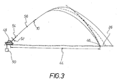
- the braking device 16 serves to reduce the longitudinal storage of the artillery projectile 10 in a target area (see Figures 3 and 4).
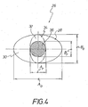
- the target area 26 is illustrated elliptically, ie with an elliptical edge 28.
- the limited by the elliptical edge 28 shelf 30 has a longitudinal axis A 0 and a transverse axis B 0 .
- the braking device 16 results in a reduction of the longitudinal shelf, ie the longitudinal axis A 0 , to an amount A r .
- a reduction of the transverse axis B 0 is not effected by the braking device 16 of the artillery projectile 10, ie by the braking device 16, the storage surface 30 is reduced to a storage surface 32 which is bounded by the edge line 34.
- pulse elements 24 is obtained by appropriate activation of the corresponding pulse elements 24 in an artillery projectile 10 with braking device 16, a reduction of the cross-placement of the artillery projectile 10, ie a further reduction of the shelf 32 to a storage area 36 through the Edge line 38 is limited.
- the support surface 36 is determined in the x-direction by the longitudinal dimension A r and in the y-direction by the transverse dimension B r , wherein it is preferred if A r and B r are the same size, so that a circular support surface 36 results.
- FIG. 2 illustrates a design of the artillery projectile 10 in a longitudinal cross-sectional view similar to FIG. 1, with the impulse elements 24 being distributed uniformly on a ring element 40 in the circumferential direction, which is arranged between the projectile fuze 14 and the projectile housing 42.
- the pyrotechnic force elements 18 are used in this embodiment of the artillery projectile 10 only for blowing off the brake device 16 covering the hood 22nd
- the pulse elements in the tail part (base bleed) of the artillery projectile 10 may be evenly distributed circumferentially.
- reference numeral 50 denotes a Feuerleitrechner.
- the fire control computer 50 determines the azimuth orientation, the elevation indicated by the double arrow 52, and the propellant charge power, i.e., depending on the pre-cleared direction and distance 44 from a gun 48 to a target 46. the theoretical exit velocity 54 for the ballistic trajectory 56 of the artillery projectile 10 in the target area 26th
Landscapes
- Physics & Mathematics (AREA)
- Fluid Mechanics (AREA)
- Engineering & Computer Science (AREA)
- General Engineering & Computer Science (AREA)
- Aiming, Guidance, Guns With A Light Source, Armor, Camouflage, And Targets (AREA)
- Braking Arrangements (AREA)
- Organic Low-Molecular-Weight Compounds And Preparation Thereof (AREA)
- Steroid Compounds (AREA)
Abstract
Description
- Die Erfindung betrifft ein drallstabilisiertes Artillerieprojektil gemäß dem Oberbegriff des Anspruches 1.
- Ein derartiges drallstabilisiertes Artillerieprojektil ist aus der
DE 101 43 312 C1 und ausDE 102 42 588 B4 bekannt. Dieses Artillerieprojektil weist in seiner Ogive eine radial anstellende Bremseinrichtung auf, die zur Reduktion der Längsablage des Artillerieprojektiles in einem Zielgebiet dient. Damit ist eine 1 D-Korrektur möglich. - Die Ablagefläche eines Artillerieprojektiles in einem Zielgebiet ist ellipsenförmig, sie weist also eine Längsachse und eine dazu orthogonale Querachse auf. Die Längsachse, d.h. die Längsablage, ist größer als die Querachse, d.h. die Querablage. Die Bremseinrichtung des bekannten drallstabilisierten Artillerieprojektiles dient dazu, die im Vergleich zur Querablage große Längsablage des Artillerieprojektiles im Zielgebiet zu reduzieren und somit die Zielgenauigkeit entsprechend zu verbessern.
- Der Erfindung liegt die Aufgabe zugrunde, ein drallstabilisiertes Artillerieprojektil der eingangs genannten Art zu schaffen, bei dem mit einfachen Mitteln auch die Querablage des Artillerieprojektiles im Zielgebiet reduziert und somit die Zielgenauigkeit entsprechend verbessert ist.
- Diese Aufgabe wird erfindungsgemäß durch die Merkmale des Anspruches 1 gelöst. Bevorzugte Aus- bzw. Weiterbildungen des erfindungsgemäßen bahnkorrigierenden drallstabilisierten Artillerieprojektiles sind in den Unteransprüchen gekennzeichnet.
- Dadurch, dass bei dem erfindungsgemäßen drallstabilisierten Artillerieprojektil am Umfang verteilt eine Anzahl Impulselemente vorgesehen sind, ist es möglich, durch passende Aktivierung mindestens eines entsprechenden Impulselementes eine Reduktion der Querablage des Artillerieprojektiles im Zielgebiet zu bewirken. Mit dem erfindungsgemäßen Artillerieprojektil wird zusätzlich zur Reduktion der Längsablage auch eine Reduktion der Querablage des Artillerieprojektiles im Zielgebiet und somit auf relativ einfache Weise eine wesentliche Verbesserung der Zielgenauigkeit realisiert. Vorteilhaft ist es hierbei, wenn die Impulselemente am Umfang des Artillerieprojektiles gleichmäßig verteilt angeordnet sind, weil dann die Ansteuerung des jeweils passenden Impulselementes vergleichsweise einfach möglich ist.
- Bei dem erfindungsgemäßen drallstabilisierten Artillerieprojektil können die Impulselemente in der Ogive des Artillerieprojektiles vorgesehen sein. Bei einer derartigen Ausbildung können die Impulselemente von den pyrotechnischen Kraftelementen gebildet sein, die einem vorderen Ringbereich einer die Bremseinrichtung bedeckenden Haube zugeordnet sind, und mittels welchem die Haube von der Ogive des Artillerieprojektiles absprengbar ist. Derartige Impulselemente in Gestalt pyrotechnischer Kraftelemente sind in der eingangs zitierten
DE 101 43 312 C1 beschrieben. - Eine andere Möglichkeit besteht darin, dass die Impulselemente an einem Ringelement vorgesehen sind, das zwischen dem Projektilzünder und dem Projektilgehäuse angeordnet ist. Auch eine solche Ausbildung der zuletzt genannten Art weist den Vorteil auf, dass das Artillerieprojektil quasi unverändert mit einem bekannten Projektilzünder kombiniert werden kann.
- Insbesondere bei Artillerieprojektilen großer Reichweite kann es bevorzugt sein, wenn die Impulselemente im Heckteil, d.h. im Base Bleed, des Artillerieprojektiles vorgesehen sind.
- Zur Bestimmung der jeweiligen zeitlichen Drehwinkelposition des Artillerieprojektiles und somit der an seinem Umfang verteilt vorgesehenen Impulselemente dient eine Einrichtung, die mit den Impulselementen, zu deren gezielter Aktivierung, zusammenwirkt. Diese Einrichtung kann im Artillerieprojektil vorgesehen sein, so dass sich eine autarke Einrichtung und ein autarkes Artillerieprojektil ergibt. Eine andere Möglichkeit besteht darin, dass diese Einrichtung satellitengestützt gesteuert wird. Eine satellitengestützte Steuerung eines bahnkorrigierbaren drallstabilisierten Artillerieprojektiles der eingangs genannten Art, d.h. zur Reduktion der Längsablage des Artillerieprojektiles in einem Zielgebiet, ist in der
EP 1 103 779 B1 beschrieben, deren Offenbarungsgehalt, was die gezielte Aktivierung der am Umfang des Artillerieprojektiles vorgesehenen Impulselemente zur Reduktion der Querablage des Artillerieprojektiles in einem Zielgebiet anbelangt, Teil der vorliegenden Erfindung ist. - Das erfindungsgemäße bahnkorrigierbare drallstabilisierte Artillerieprojektil weist den Vorteil auf, dass mit konstruktiv einfachen Mitteln zusätzlich zur Reduktion der Längsablage eine Reduktion der Querablage des Artillerieprojektiles in einem Zielgebiet verwirklicht wird. Dabei wird die Reduktion der Querablage, d.h. die gesteuerte Seitenkorrektur des Artillerieprojektiles, zeitlich vor der Aktivierung der Bremseinrichtung zur Reduktion der Längsablage des Artillerieprojektiles im Zielgebiet durchgeführt, weil die Seitenkorrektur zeitlich schneller erfolgt als die Bremseinrichtung zur Reduktion der Längsablage wirksam wird.
- Während bei dem bekannten drallstabilisierten Artillerieprojektil mit einer Reduktion der Längsablage also eine 1D-Korrektur erfolgt, ergibt sich beim erfindungsgemäßen Artillerieprojektil eine 1,5D-Korrektur.
- Weitere Einzelheiten, Merkmale und Vorteile ergeben sich aus der nachfolgenden Beschreibung zweier in der Zeichnung verdeutlichter Ausführungsbeispiele des erfindungsgemäßen drallstabilisierten Artillerieprojektiles und seiner Wirkungsweise.
- Es zeigen:
- Figur 1
- abgeschnitten in einer Längsschnittdarstellung eine erste Ausbildung des Artillerieprojektiles,
- Figur 2
- eine der Figur 1 ähnliche Darstellung einer zweiten Ausführungsform des Artillerieprojektiles,
- Figur 3
- die Verbringung eines ballistisch gestarteten drallstabilisierten Artillerieprojektiles aus einem Geschütz in ein Zielgebiet, und
- Figur 4
- eine Draufsicht auf ein Zielgebiet, bei dem sowohl die Längsablage in der x-Richtung als auch die Querablage in der y-Richtung reduziert und folglich die Zielgenauigkeit entsprechend verbessert ist.
- Figur 1 zeigt längsgeschnitten den Vorderabschnitt einer Ausbildung des drallstabilisierten Artillerieprojektiles 10 mit einem in seiner Ogive 12 vorgesehenen Projektilzünder 14 und einer in der Ogive 12 vorgesehenen Bremseinrichtung 16, die fliehkraftbedingt durch pyrotechnische Kraftelemente 18 anstellbar ist, die einem vorderen Ringbereich 20 einer Haube 22 zugeordnet sind.
- Die pyrotechnischen Kraftelemente 18 bilden Impulselemente 24 des Artillerieprojektiles 10, die am Umfang des Artillerieprojektiles 10 gleichmäßig verteilt angeordnet sind.
- Die Bremseinrichtung 16 dient zur Reduktion der Längsablage des Artillerieprojektiles 10 in einem Zielgebiet (siehe die Figuren 3 und 4). In Figur 4 ist das Zielgebiet 26 ellipsenförmig, d.h. mit einem elliptischen Rand 28, verdeutlicht. Die durch den elliptischen Rand 28 begrenzte Ablagefläche 30 weist eine Längsachse A0 und eine Querachse B0 auf. Durch die Bremseinrichtung 16 ergibt sich eine Reduktion der Längsablage, d.h. der Längsachse A0, zu einem Betrag Ar. Eine Reduktion der Querachse B0 wird durch die Bremseinrichtung 16 des Artillerieprojektiles 10 nicht bewirkt, d.h. durch die Bremseinrichtung 16 wird die Ablagefläche 30 zu einer Ablagefläche 32 verkleinert, die durch die Randlinie 34 begrenzt ist.
- Mit Hilfe der am Umfang des Artillerieprojektiles 10 verteilten Impulselemente 24 ergibt sich durch passende Aktivierung der entsprechenden Impulselemente 24 bei einem Artillerieprojektil 10 mit Bremseinrichtung 16 eine Reduktion der Querablage des Artillerieprojektiles 10, d.h. eine weitere Reduktion der Ablagefläche 32 zu einer Ablagefläche 36, die durch die Randlinie 38 begrenzt ist. Die Ablagefläche 36 ist in x-Richtung durch die Längsabmessung Ar und in y-Richtung durch die Querabmessung Br bestimmt, wobei es bevorzugt ist, wenn Ar und Br gleich groß sind, so dass sich eine kreisrunde Ablagefläche 36 ergibt.
- Bezüglich weiterer Einzelheiten des Artillerieprojektiles 10 gemäß Figur 1 wird auf die eingangs zitierte
DE 101 43 312 C1 Bezug genommen, deren Inhalt insofern zum Offenbarungsgehalt der vorliegenden Patentanmeldung gehört. Gleiches gilt für dieDE 102 42 588 B4 , bei der es sich um ein Zusatzpatent zurDE 101 43 312 C1 handelt. - Figur 2 verdeutlicht eine Ausbildung des Artillerieprojektiles 10 in einer der Figur 1 ähnlichen abgeschnittenen Längsschnittdarstellung, wobei die Impulselemente 24 an einem Ringelement 40 in Umfangsrichtung gleichmäßig verteilt vorgesehen sind, das zwischen dem Projektilzünder 14 und dem Projektilgehäuse 42 angeordnet ist. Die pyrotechnischen Kraftelemente 18 dienen bei dieser Ausführungsform des Artillerieprojektiles 10 nur zum Absprengen der die Bremseinrichtung 16 bedeckenden Haube 22.
- Insbesondere bei Artillerieprojektilen 10 großer Reichweite 44 (siehe Figur 3) zwischen einem Ziel 46 und einem Geschütz 48, aus dem das Artillerieprojektil 10 abgefeuert wird, können die Impulselemente im Heckteil (Base Bleed) des Artillerieprojektiles 10 in Umfangsrichtung gleichmäßig verteilt vorgesehen sein.
- In Figur 3 ist mit Bezugsziffer 50 ein Feuerleitrechner bezeichnet. Der Feuerleitrechner 50 bestimmt je nach der voraufgeklärten Richtung und Entfernung 44 von einem Geschütz 48 zu einem Ziel 46 die Azimutausrichtung, die durch den Doppelpfeil 52 angedeutete Elevation und die Treibladungsleistung, d.h. die theoretische Abgangsgeschwindigkeit 54 für die ballistische Bahnkurve 56 des Artillerieprojektiles 10 in das Zielgebiet 26.
- Bezüglich der Reduktion der Längsablage des Artillerieprojektiles und des entsprechenden Verfahrens zur zielbezogenen Korrektur der ballistischen Flugbahn wird auf die eingangs zitierte
EP 1 103 779 B1 Bezug genommen, die diesbezüglich ebenfalls zum Offenbarungsgehalt der vorliegenden Patentanmeldung gehört. -
- 10
- Artillerieprojektil
- 12
- Ogive (von 10)
- 14
- Projektilzünder (in 12)
- 16
- Bremseinrichtung (von 10)
- 18
- pyrotechnische Kraftelemente (für 20)
- 20
- vorderer Ringbereich (von 22)
- 22
- Haube (für 16)
- 24
- Impulselemente (von 10)
- 26
- Zielgebiet (von 10 bei 46)
- 28
- elliptischer Rand (von 30)
- 30
- Ablagefläche
- 32
- 1 D-reduzierte Ablagefläche
- 34
- Randlinie (von 32)
- 36
- 1,5D-reduzierte Ablagefläche
- 38
- Randlinie (von 36)
- 40
- Ringelement (zwischen 14 und 42 für 24)
- 42
- Projektilgehäuse (von 10)
- 44
- Reichweite (von 10 zwischen 48 und 46)
- 46
- Ziel
- 48
- Geschütz (für 10)
- 50
- Feuerleitrechner (für 48)
- 52
- Doppelpfeil/Elevation (von 48)
- 54
- Abgangsgeschwindigkeit (von 10)
- 56
- Ballistische Bahnkurve (von 10 zwischen 48 und 26)
Claims (9)
- Drallstabilisiertes Artillerieprojektil mit einem in seiner Ogive (12) vorgesehenen Projektilzünder (14) und einer in der Ogive (12) vorgesehenen, radial ausstellenden Bremseinrichtung (16) zur Reduktion der Längsablage (A0; Ar) des Artillerieprojektiles (10) in einem Zielgebiet (26),
dadurch gekennzeichnet,
dass das Artillerieprojektil (10) an seinem Umfang verteilt eine Anzahl Impulselemente (24) aufweist, die zur Reduktion der Querablage (B0; Br) des Artillerieprojektiles (10) im Zielgebiet (26) vorgesehen sind. - Artillerieprojektil nach Anspruch 1,
dadurch gekennzeichnet,
dass die Impulselemente (24) am Umfang des Artillerieprojektiles gleichmäßig verteilt angeordnet sind. - Artillerieprojektil nach Anspruch 1 oder 2,
dadurch gekennzeichnet,
dass die Impulselemente (24) in der Ogive (12) des Artillerieprojektiles (10) vorgesehen sind. - Artillerieprojektil nach Anspruch 3,
dadurch gekennzeichnet,
dass die Impulselemente (24) von pyrotechnischen Kraftelementen (18) gebildet sind, die einem vorderen Ringbereich (20) einer die Bremseinrichtung (16) bedeckenden Haube (22) zugeordnet sind, und mittels welchem die Haube (22) von der Ogive (12) des Artillerieprojektiles (10) absprengbar ist. - Artillerieprojektil nach Anspruch 3,
dadurch gekennzeichnet,
dass die Impulselemente (24) an einem Ringelement (40) vorgesehen sind, das zwischen dem Projektilzünder (14) und dem Projektilgehäuse (42) angeordnet ist. - Artillerieprojektil nach Anspruch 3,
dadurch gekennzeichnet,
dass die Impulselemente (24) im Heckteil (Base Bleed) des Artillerieprojektiles (10) vorgesehen sind. - Artillerieprojektil nach einem der Ansprüche 1 bis 6,
dadurch gekennzeichnet,
dass zur Bestimmung der jeweiligen zeitlichen Drehwinkelposition des Artillerieprojektiles (10) und somit der voneinander in Umfangsrichtung beabstandeten Impulselemente (24) eine Einrichtung vorgesehen ist, die mit den Impulselementen (24), zu deren gezielter Aktivierung, wirkverbunden ist. - Artillerieprojektil nach Anspruch 7,
dadurch gekennzeichnet,
dass die Einrichtung im Artillerieprojektil (10) vorgesehen ist. - Artillerieprojektil nach Anspruch 7,
dadurch gekennzeichnet,
dass die Einrichtung satellitengestützt gesteuert wird.
Applications Claiming Priority (1)
| Application Number | Priority Date | Filing Date | Title |
|---|---|---|---|
| DE102005052474A DE102005052474B3 (de) | 2005-11-03 | 2005-11-03 | Drallstbilisiertes Artillerieprojektil |
Publications (3)
| Publication Number | Publication Date |
|---|---|
| EP1783451A2 true EP1783451A2 (de) | 2007-05-09 |
| EP1783451A3 EP1783451A3 (de) | 2007-08-29 |
| EP1783451B1 EP1783451B1 (de) | 2008-12-17 |
Family
ID=37697820
Family Applications (1)
| Application Number | Title | Priority Date | Filing Date |
|---|---|---|---|
| EP06022695A Not-in-force EP1783451B1 (de) | 2005-11-03 | 2006-10-31 | Drallstabilisiertes Artillerieprojektil |
Country Status (5)
| Country | Link |
|---|---|
| US (1) | US7360490B2 (de) |
| EP (1) | EP1783451B1 (de) |
| AT (1) | ATE418059T1 (de) |
| DE (2) | DE102005052474B3 (de) |
| ES (1) | ES2317401T3 (de) |
Cited By (1)
| Publication number | Priority date | Publication date | Assignee | Title |
|---|---|---|---|---|
| FR3035205A1 (fr) * | 2015-04-20 | 2016-10-21 | Roxel France | Dispositif de correction de trajectoire d'un projectile et procede de correction de trajectoire |
Families Citing this family (1)
| Publication number | Priority date | Publication date | Assignee | Title |
|---|---|---|---|---|
| CN115358638A (zh) * | 2022-10-19 | 2022-11-18 | 中国兵器科学研究院 | 一种火力分配方法、装置、电子设备及存储介质 |
Citations (3)
| Publication number | Priority date | Publication date | Assignee | Title |
|---|---|---|---|---|
| DE10143312C1 (de) | 2001-09-04 | 2003-06-18 | Diehl Munitionssysteme Gmbh | Bremseinrichtung für ein bahnkorrigierbares drallstabilisiertes Artillerieprojektil |
| EP1103779B1 (de) | 1999-11-29 | 2004-02-04 | Diehl Munitionssysteme GmbH & Co. KG | Verfahren zur zielbezogenen Korrektur einer ballistischen Flugbahn |
| DE10242588B4 (de) | 2001-09-04 | 2005-06-30 | Diehl Bgt Defence Gmbh & Co. Kg | Bremseinrichtung für ein bahnkorrigierbares drallstabilisiertes Artillerieprojektil |
Family Cites Families (9)
| Publication number | Priority date | Publication date | Assignee | Title |
|---|---|---|---|---|
| DE2809281C2 (de) * | 1978-03-03 | 1984-01-05 | Emile Jean Versailles Stauff | Steuervorrichtung für ein Geschoß mit Eigendrehung |
| DE3546269C1 (de) * | 1985-12-28 | 1987-08-13 | Deutsche Forsch Luft Raumfahrt | Flugkoerper |
| FR2686687B1 (fr) * | 1987-04-22 | 1994-05-13 | Thomson Brandt Armements | Procede et dispositif de pilotage d'un projectile selon ses trois axes de roulis tangage et lacet. |
| EP0418636B1 (de) * | 1989-09-19 | 1993-12-29 | DIEHL GMBH & CO. | Bahnkorrigierbares Projektil |
| DE4036166A1 (de) * | 1990-11-14 | 1992-05-21 | Diehl Gmbh & Co | Bahnkorrigierbares projektil |
| US5456429A (en) * | 1993-08-02 | 1995-10-10 | Loral Corp. | Thrust maneuver system |
| US5647558A (en) * | 1995-02-14 | 1997-07-15 | Bofors Ab | Method and apparatus for radial thrust trajectory correction of a ballistic projectile |
| EP1540264B1 (de) | 2002-09-13 | 2010-06-09 | Diehl BGT Defence GmbH & Co.KG | Bremseinrichtung für ein bahnkorrigierbares drallstabilisiertes artillerieprojektil |
| US7121210B2 (en) * | 2003-02-18 | 2006-10-17 | Kdi Precision Products, Inc. | Accuracy fuze for airburst cargo delivery projectiles |
-
2005
- 2005-11-03 DE DE102005052474A patent/DE102005052474B3/de not_active Expired - Fee Related
-
2006
- 2006-10-26 US US11/586,907 patent/US7360490B2/en not_active Expired - Fee Related
- 2006-10-31 ES ES06022695T patent/ES2317401T3/es active Active
- 2006-10-31 AT AT06022695T patent/ATE418059T1/de not_active IP Right Cessation
- 2006-10-31 EP EP06022695A patent/EP1783451B1/de not_active Not-in-force
- 2006-10-31 DE DE502006002369T patent/DE502006002369D1/de active Active
Patent Citations (3)
| Publication number | Priority date | Publication date | Assignee | Title |
|---|---|---|---|---|
| EP1103779B1 (de) | 1999-11-29 | 2004-02-04 | Diehl Munitionssysteme GmbH & Co. KG | Verfahren zur zielbezogenen Korrektur einer ballistischen Flugbahn |
| DE10143312C1 (de) | 2001-09-04 | 2003-06-18 | Diehl Munitionssysteme Gmbh | Bremseinrichtung für ein bahnkorrigierbares drallstabilisiertes Artillerieprojektil |
| DE10242588B4 (de) | 2001-09-04 | 2005-06-30 | Diehl Bgt Defence Gmbh & Co. Kg | Bremseinrichtung für ein bahnkorrigierbares drallstabilisiertes Artillerieprojektil |
Cited By (2)
| Publication number | Priority date | Publication date | Assignee | Title |
|---|---|---|---|---|
| FR3035205A1 (fr) * | 2015-04-20 | 2016-10-21 | Roxel France | Dispositif de correction de trajectoire d'un projectile et procede de correction de trajectoire |
| WO2016169760A1 (fr) * | 2015-04-20 | 2016-10-27 | Roxel France | Dispositif de correction de trajectoire d'un projectile et procede de correction de trajectoire |
Also Published As
| Publication number | Publication date |
|---|---|
| ATE418059T1 (de) | 2009-01-15 |
| EP1783451A3 (de) | 2007-08-29 |
| US7360490B2 (en) | 2008-04-22 |
| DE502006002369D1 (de) | 2009-01-29 |
| US20070095238A1 (en) | 2007-05-03 |
| EP1783451B1 (de) | 2008-12-17 |
| DE102005052474B3 (de) | 2007-07-12 |
| ES2317401T3 (es) | 2009-04-16 |
Similar Documents
| Publication | Publication Date | Title |
|---|---|---|
| EP0806623B1 (de) | Drallstabilisierbares, eine Nutzlast enthaltendes Projektil | |
| DE3317352C2 (de) | Einlage für eine projektilbildende Ladung | |
| DE3887319T2 (de) | Geschoss für feuerwaffen. | |
| DE3137855C2 (de) | ||
| DE102007059397A1 (de) | Taumelzünder | |
| DE3934042C2 (de) | ||
| DE2428624A1 (de) | Granatenabfeuervorrichtung | |
| DE2519507A1 (de) | Munition zur bekaempfung von zielen, insbesondere flugzielen im vorbeiflug | |
| DE3235404A1 (de) | Sprengladung | |
| WO2018177713A1 (de) | Geschoss, insbesondere im mittelkaliberbereich | |
| DE102008037917B4 (de) | Umschaltbare zylindrische Wirkladung | |
| EP1783451B1 (de) | Drallstabilisiertes Artillerieprojektil | |
| DE3501649A1 (de) | Gefechtskopf mit strahlbildender spitzkegel-einlage | |
| DE10025055C2 (de) | Splittererzeugender Gefechtskopf zur Bekämpfung halbharter technischer Ziele | |
| EP0485897B1 (de) | Bahnkorrigierbares Projektil | |
| DE3904625C2 (de) | ||
| DE19752102B4 (de) | Panzerbrechendes Geschoß mit Wuchtwirkung | |
| AT407573B (de) | Zündnadel für geschosszünder | |
| DE19531287B4 (de) | Gefechtskopf | |
| DE102011011478A1 (de) | Zerlegegeschoss | |
| DE102007054382A1 (de) | De-Letalisierbare Munition | |
| DE4331236C1 (de) | Gefechtskopf zur Bekämpfung gepanzerter Ziele | |
| DE1578077C2 (de) | Gefechtskopf fuer ein Panzerabwehrgeschoss | |
| DE4108633C2 (de) | Verwendung des scharfen Wirkteiles einer Suchzünder-Submunition als Übungsmunition mit reduzierter Reichweite | |
| DE102010027577B4 (de) | Gefechtskopf |
Legal Events
| Date | Code | Title | Description |
|---|---|---|---|
| PUAI | Public reference made under article 153(3) epc to a published international application that has entered the european phase |
Free format text: ORIGINAL CODE: 0009012 |
|
| AK | Designated contracting states |
Kind code of ref document: A2 Designated state(s): AT BE BG CH CY CZ DE DK EE ES FI FR GB GR HU IE IS IT LI LT LU LV MC NL PL PT RO SE SI SK TR |
|
| AX | Request for extension of the european patent |
Extension state: AL BA HR MK YU |
|
| PUAL | Search report despatched |
Free format text: ORIGINAL CODE: 0009013 |
|
| AK | Designated contracting states |
Kind code of ref document: A3 Designated state(s): AT BE BG CH CY CZ DE DK EE ES FI FR GB GR HU IE IS IT LI LT LU LV MC NL PL PT RO SE SI SK TR |
|
| AX | Request for extension of the european patent |
Extension state: AL BA HR MK YU |
|
| 17P | Request for examination filed |
Effective date: 20070911 |
|
| RAP1 | Party data changed (applicant data changed or rights of an application transferred) |
Owner name: JUNGHANS MICROTEC GMBH |
|
| 17Q | First examination report despatched |
Effective date: 20071029 |
|
| AKX | Designation fees paid |
Designated state(s): AT BE BG CH CY CZ DE DK EE ES FI FR GB GR HU IE IS IT LI LT LU LV MC NL PL PT RO SE SI SK TR |
|
| GRAP | Despatch of communication of intention to grant a patent |
Free format text: ORIGINAL CODE: EPIDOSNIGR1 |
|
| RIC1 | Information provided on ipc code assigned before grant |
Ipc: F42B 10/66 20060101ALN20080716BHEP Ipc: F42B 10/50 20060101AFI20080716BHEP |
|
| GRAS | Grant fee paid |
Free format text: ORIGINAL CODE: EPIDOSNIGR3 |
|
| GRAA | (expected) grant |
Free format text: ORIGINAL CODE: 0009210 |
|
| AK | Designated contracting states |
Kind code of ref document: B1 Designated state(s): AT BE BG CH CY CZ DE DK EE ES FI FR GB GR HU IE IS IT LI LT LU LV MC NL PL PT RO SE SI SK TR |
|
| REG | Reference to a national code |
Ref country code: GB Ref legal event code: FG4D Free format text: NOT ENGLISH |
|
| REG | Reference to a national code |
Ref country code: CH Ref legal event code: EP |
|
| REG | Reference to a national code |
Ref country code: IE Ref legal event code: FG4D Free format text: LANGUAGE OF EP DOCUMENT: GERMAN |
|
| REF | Corresponds to: |
Ref document number: 502006002369 Country of ref document: DE Date of ref document: 20090129 Kind code of ref document: P |
|
| REG | Reference to a national code |
Ref country code: SE Ref legal event code: TRGR |
|
| REG | Reference to a national code |
Ref country code: ES Ref legal event code: FG2A Ref document number: 2317401 Country of ref document: ES Kind code of ref document: T3 |
|
| PG25 | Lapsed in a contracting state [announced via postgrant information from national office to epo] |
Ref country code: LT Free format text: LAPSE BECAUSE OF FAILURE TO SUBMIT A TRANSLATION OF THE DESCRIPTION OR TO PAY THE FEE WITHIN THE PRESCRIBED TIME-LIMIT Effective date: 20081217 |
|
| PG25 | Lapsed in a contracting state [announced via postgrant information from national office to epo] |
Ref country code: PL Free format text: LAPSE BECAUSE OF FAILURE TO SUBMIT A TRANSLATION OF THE DESCRIPTION OR TO PAY THE FEE WITHIN THE PRESCRIBED TIME-LIMIT Effective date: 20081217 Ref country code: NL Free format text: LAPSE BECAUSE OF FAILURE TO SUBMIT A TRANSLATION OF THE DESCRIPTION OR TO PAY THE FEE WITHIN THE PRESCRIBED TIME-LIMIT Effective date: 20081217 Ref country code: LV Free format text: LAPSE BECAUSE OF FAILURE TO SUBMIT A TRANSLATION OF THE DESCRIPTION OR TO PAY THE FEE WITHIN THE PRESCRIBED TIME-LIMIT Effective date: 20081217 Ref country code: SI Free format text: LAPSE BECAUSE OF FAILURE TO SUBMIT A TRANSLATION OF THE DESCRIPTION OR TO PAY THE FEE WITHIN THE PRESCRIBED TIME-LIMIT Effective date: 20081217 |
|
| NLV1 | Nl: lapsed or annulled due to failure to fulfill the requirements of art. 29p and 29m of the patents act | ||
| REG | Reference to a national code |
Ref country code: IE Ref legal event code: FD4D |
|
| PG25 | Lapsed in a contracting state [announced via postgrant information from national office to epo] |
Ref country code: EE Free format text: LAPSE BECAUSE OF FAILURE TO SUBMIT A TRANSLATION OF THE DESCRIPTION OR TO PAY THE FEE WITHIN THE PRESCRIBED TIME-LIMIT Effective date: 20081217 Ref country code: RO Free format text: LAPSE BECAUSE OF FAILURE TO SUBMIT A TRANSLATION OF THE DESCRIPTION OR TO PAY THE FEE WITHIN THE PRESCRIBED TIME-LIMIT Effective date: 20081217 Ref country code: BG Free format text: LAPSE BECAUSE OF FAILURE TO SUBMIT A TRANSLATION OF THE DESCRIPTION OR TO PAY THE FEE WITHIN THE PRESCRIBED TIME-LIMIT Effective date: 20090317 Ref country code: IE Free format text: LAPSE BECAUSE OF FAILURE TO SUBMIT A TRANSLATION OF THE DESCRIPTION OR TO PAY THE FEE WITHIN THE PRESCRIBED TIME-LIMIT Effective date: 20081217 |
|
| PG25 | Lapsed in a contracting state [announced via postgrant information from national office to epo] |
Ref country code: CZ Free format text: LAPSE BECAUSE OF FAILURE TO SUBMIT A TRANSLATION OF THE DESCRIPTION OR TO PAY THE FEE WITHIN THE PRESCRIBED TIME-LIMIT Effective date: 20081217 Ref country code: IS Free format text: LAPSE BECAUSE OF FAILURE TO SUBMIT A TRANSLATION OF THE DESCRIPTION OR TO PAY THE FEE WITHIN THE PRESCRIBED TIME-LIMIT Effective date: 20090417 Ref country code: PT Free format text: LAPSE BECAUSE OF FAILURE TO SUBMIT A TRANSLATION OF THE DESCRIPTION OR TO PAY THE FEE WITHIN THE PRESCRIBED TIME-LIMIT Effective date: 20090518 |
|
| PG25 | Lapsed in a contracting state [announced via postgrant information from national office to epo] |
Ref country code: SK Free format text: LAPSE BECAUSE OF FAILURE TO SUBMIT A TRANSLATION OF THE DESCRIPTION OR TO PAY THE FEE WITHIN THE PRESCRIBED TIME-LIMIT Effective date: 20081217 |
|
| PLBE | No opposition filed within time limit |
Free format text: ORIGINAL CODE: 0009261 |
|
| STAA | Information on the status of an ep patent application or granted ep patent |
Free format text: STATUS: NO OPPOSITION FILED WITHIN TIME LIMIT |
|
| PG25 | Lapsed in a contracting state [announced via postgrant information from national office to epo] |
Ref country code: DK Free format text: LAPSE BECAUSE OF FAILURE TO SUBMIT A TRANSLATION OF THE DESCRIPTION OR TO PAY THE FEE WITHIN THE PRESCRIBED TIME-LIMIT Effective date: 20081217 |
|
| 26N | No opposition filed |
Effective date: 20090918 |
|
| BERE | Be: lapsed |
Owner name: JUNGHANS MICROTEC G.M.B.H. Effective date: 20091031 |
|
| PG25 | Lapsed in a contracting state [announced via postgrant information from national office to epo] |
Ref country code: MC Free format text: LAPSE BECAUSE OF NON-PAYMENT OF DUE FEES Effective date: 20091031 |
|
| PG25 | Lapsed in a contracting state [announced via postgrant information from national office to epo] |
Ref country code: BE Free format text: LAPSE BECAUSE OF NON-PAYMENT OF DUE FEES Effective date: 20091031 Ref country code: GR Free format text: LAPSE BECAUSE OF FAILURE TO SUBMIT A TRANSLATION OF THE DESCRIPTION OR TO PAY THE FEE WITHIN THE PRESCRIBED TIME-LIMIT Effective date: 20090318 |
|
| PG25 | Lapsed in a contracting state [announced via postgrant information from national office to epo] |
Ref country code: AT Free format text: LAPSE BECAUSE OF NON-PAYMENT OF DUE FEES Effective date: 20091031 |
|
| PG25 | Lapsed in a contracting state [announced via postgrant information from national office to epo] |
Ref country code: LU Free format text: LAPSE BECAUSE OF NON-PAYMENT OF DUE FEES Effective date: 20091031 |
|
| PG25 | Lapsed in a contracting state [announced via postgrant information from national office to epo] |
Ref country code: HU Free format text: LAPSE BECAUSE OF FAILURE TO SUBMIT A TRANSLATION OF THE DESCRIPTION OR TO PAY THE FEE WITHIN THE PRESCRIBED TIME-LIMIT Effective date: 20090618 |
|
| PG25 | Lapsed in a contracting state [announced via postgrant information from national office to epo] |
Ref country code: TR Free format text: LAPSE BECAUSE OF FAILURE TO SUBMIT A TRANSLATION OF THE DESCRIPTION OR TO PAY THE FEE WITHIN THE PRESCRIBED TIME-LIMIT Effective date: 20081217 |
|
| PG25 | Lapsed in a contracting state [announced via postgrant information from national office to epo] |
Ref country code: CY Free format text: LAPSE BECAUSE OF FAILURE TO SUBMIT A TRANSLATION OF THE DESCRIPTION OR TO PAY THE FEE WITHIN THE PRESCRIBED TIME-LIMIT Effective date: 20081217 |
|
| REG | Reference to a national code |
Ref country code: FR Ref legal event code: PLFP Year of fee payment: 10 |
|
| PGFP | Annual fee paid to national office [announced via postgrant information from national office to epo] |
Ref country code: DE Payment date: 20151223 Year of fee payment: 10 |
|
| REG | Reference to a national code |
Ref country code: FR Ref legal event code: PLFP Year of fee payment: 11 |
|
| PGFP | Annual fee paid to national office [announced via postgrant information from national office to epo] |
Ref country code: FI Payment date: 20161012 Year of fee payment: 11 Ref country code: CH Payment date: 20161020 Year of fee payment: 11 Ref country code: FR Payment date: 20161020 Year of fee payment: 11 Ref country code: GB Payment date: 20161020 Year of fee payment: 11 |
|
| PGFP | Annual fee paid to national office [announced via postgrant information from national office to epo] |
Ref country code: SE Payment date: 20161019 Year of fee payment: 11 Ref country code: ES Payment date: 20161011 Year of fee payment: 11 Ref country code: IT Payment date: 20161024 Year of fee payment: 11 |
|
| REG | Reference to a national code |
Ref country code: DE Ref legal event code: R119 Ref document number: 502006002369 Country of ref document: DE |
|
| PG25 | Lapsed in a contracting state [announced via postgrant information from national office to epo] |
Ref country code: DE Free format text: LAPSE BECAUSE OF NON-PAYMENT OF DUE FEES Effective date: 20170503 |
|
| REG | Reference to a national code |
Ref country code: CH Ref legal event code: PL |
|
| GBPC | Gb: european patent ceased through non-payment of renewal fee |
Effective date: 20171031 |
|
| REG | Reference to a national code |
Ref country code: SE Ref legal event code: EUG |
|
| REG | Reference to a national code |
Ref country code: FR Ref legal event code: ST Effective date: 20180629 |
|
| PG25 | Lapsed in a contracting state [announced via postgrant information from national office to epo] |
Ref country code: CH Free format text: LAPSE BECAUSE OF NON-PAYMENT OF DUE FEES Effective date: 20171031 Ref country code: FI Free format text: LAPSE BECAUSE OF NON-PAYMENT OF DUE FEES Effective date: 20171031 Ref country code: LI Free format text: LAPSE BECAUSE OF NON-PAYMENT OF DUE FEES Effective date: 20171031 Ref country code: GB Free format text: LAPSE BECAUSE OF NON-PAYMENT OF DUE FEES Effective date: 20171031 |
|
| PG25 | Lapsed in a contracting state [announced via postgrant information from national office to epo] |
Ref country code: SE Free format text: LAPSE BECAUSE OF NON-PAYMENT OF DUE FEES Effective date: 20171101 Ref country code: FR Free format text: LAPSE BECAUSE OF NON-PAYMENT OF DUE FEES Effective date: 20171031 |
|
| PG25 | Lapsed in a contracting state [announced via postgrant information from national office to epo] |
Ref country code: IT Free format text: LAPSE BECAUSE OF NON-PAYMENT OF DUE FEES Effective date: 20171031 |
|
| REG | Reference to a national code |
Ref country code: ES Ref legal event code: FD2A Effective date: 20181226 |
|
| PG25 | Lapsed in a contracting state [announced via postgrant information from national office to epo] |
Ref country code: ES Free format text: LAPSE BECAUSE OF NON-PAYMENT OF DUE FEES Effective date: 20171101 |