EP1781400B1 - Cleaning of combustion gas including the removal of co2 - Google Patents
Cleaning of combustion gas including the removal of co2 Download PDFInfo
- Publication number
- EP1781400B1 EP1781400B1 EP05735524.0A EP05735524A EP1781400B1 EP 1781400 B1 EP1781400 B1 EP 1781400B1 EP 05735524 A EP05735524 A EP 05735524A EP 1781400 B1 EP1781400 B1 EP 1781400B1
- Authority
- EP
- European Patent Office
- Prior art keywords
- solution
- range
- slurry
- stream
- temperature
- Prior art date
- Legal status (The legal status is an assumption and is not a legal conclusion. Google has not performed a legal analysis and makes no representation as to the accuracy of the status listed.)
- Active
Links
Images

Classifications
-
- B—PERFORMING OPERATIONS; TRANSPORTING
- B01—PHYSICAL OR CHEMICAL PROCESSES OR APPARATUS IN GENERAL
- B01D—SEPARATION
- B01D53/00—Separation of gases or vapours; Recovering vapours of volatile solvents from gases; Chemical or biological purification of waste gases, e.g. engine exhaust gases, smoke, fumes, flue gases, aerosols
- B01D53/14—Separation of gases or vapours; Recovering vapours of volatile solvents from gases; Chemical or biological purification of waste gases, e.g. engine exhaust gases, smoke, fumes, flue gases, aerosols by absorption
-
- B—PERFORMING OPERATIONS; TRANSPORTING
- B01—PHYSICAL OR CHEMICAL PROCESSES OR APPARATUS IN GENERAL
- B01D—SEPARATION
- B01D53/00—Separation of gases or vapours; Recovering vapours of volatile solvents from gases; Chemical or biological purification of waste gases, e.g. engine exhaust gases, smoke, fumes, flue gases, aerosols
- B01D53/34—Chemical or biological purification of waste gases
- B01D53/46—Removing components of defined structure
- B01D53/62—Carbon oxides
-
- B—PERFORMING OPERATIONS; TRANSPORTING
- B01—PHYSICAL OR CHEMICAL PROCESSES OR APPARATUS IN GENERAL
- B01D—SEPARATION
- B01D53/00—Separation of gases or vapours; Recovering vapours of volatile solvents from gases; Chemical or biological purification of waste gases, e.g. engine exhaust gases, smoke, fumes, flue gases, aerosols
- B01D53/14—Separation of gases or vapours; Recovering vapours of volatile solvents from gases; Chemical or biological purification of waste gases, e.g. engine exhaust gases, smoke, fumes, flue gases, aerosols by absorption
- B01D53/1456—Removing acid components
- B01D53/1475—Removing carbon dioxide
-
- B—PERFORMING OPERATIONS; TRANSPORTING
- B01—PHYSICAL OR CHEMICAL PROCESSES OR APPARATUS IN GENERAL
- B01D—SEPARATION
- B01D53/00—Separation of gases or vapours; Recovering vapours of volatile solvents from gases; Chemical or biological purification of waste gases, e.g. engine exhaust gases, smoke, fumes, flue gases, aerosols
- B01D53/34—Chemical or biological purification of waste gases
- B01D53/74—General processes for purification of waste gases; Apparatus or devices specially adapted therefor
- B01D53/75—Multi-step processes
-
- F—MECHANICAL ENGINEERING; LIGHTING; HEATING; WEAPONS; BLASTING
- F23—COMBUSTION APPARATUS; COMBUSTION PROCESSES
- F23J—REMOVAL OR TREATMENT OF COMBUSTION PRODUCTS OR COMBUSTION RESIDUES; FLUES
- F23J15/00—Arrangements of devices for treating smoke or fumes
- F23J15/006—Layout of treatment plant
-
- F—MECHANICAL ENGINEERING; LIGHTING; HEATING; WEAPONS; BLASTING
- F23—COMBUSTION APPARATUS; COMBUSTION PROCESSES
- F23J—REMOVAL OR TREATMENT OF COMBUSTION PRODUCTS OR COMBUSTION RESIDUES; FLUES
- F23J15/00—Arrangements of devices for treating smoke or fumes
- F23J15/06—Arrangements of devices for treating smoke or fumes of coolers
-
- B—PERFORMING OPERATIONS; TRANSPORTING
- B01—PHYSICAL OR CHEMICAL PROCESSES OR APPARATUS IN GENERAL
- B01D—SEPARATION
- B01D2251/00—Reactants
- B01D2251/20—Reductants
- B01D2251/206—Ammonium compounds
- B01D2251/2062—Ammonia
-
- B—PERFORMING OPERATIONS; TRANSPORTING
- B01—PHYSICAL OR CHEMICAL PROCESSES OR APPARATUS IN GENERAL
- B01D—SEPARATION
- B01D2252/00—Absorbents, i.e. solvents and liquid materials for gas absorption
- B01D2252/10—Inorganic absorbents
- B01D2252/102—Ammonia
-
- F—MECHANICAL ENGINEERING; LIGHTING; HEATING; WEAPONS; BLASTING
- F23—COMBUSTION APPARATUS; COMBUSTION PROCESSES
- F23J—REMOVAL OR TREATMENT OF COMBUSTION PRODUCTS OR COMBUSTION RESIDUES; FLUES
- F23J2215/00—Preventing emissions
- F23J2215/50—Carbon dioxide
-
- F—MECHANICAL ENGINEERING; LIGHTING; HEATING; WEAPONS; BLASTING
- F23—COMBUSTION APPARATUS; COMBUSTION PROCESSES
- F23J—REMOVAL OR TREATMENT OF COMBUSTION PRODUCTS OR COMBUSTION RESIDUES; FLUES
- F23J2219/00—Treatment devices
- F23J2219/50—Sorption with semi-dry devices, e.g. with slurries
-
- Y—GENERAL TAGGING OF NEW TECHNOLOGICAL DEVELOPMENTS; GENERAL TAGGING OF CROSS-SECTIONAL TECHNOLOGIES SPANNING OVER SEVERAL SECTIONS OF THE IPC; TECHNICAL SUBJECTS COVERED BY FORMER USPC CROSS-REFERENCE ART COLLECTIONS [XRACs] AND DIGESTS
- Y02—TECHNOLOGIES OR APPLICATIONS FOR MITIGATION OR ADAPTATION AGAINST CLIMATE CHANGE
- Y02A—TECHNOLOGIES FOR ADAPTATION TO CLIMATE CHANGE
- Y02A50/00—TECHNOLOGIES FOR ADAPTATION TO CLIMATE CHANGE in human health protection, e.g. against extreme weather
- Y02A50/20—Air quality improvement or preservation, e.g. vehicle emission control or emission reduction by using catalytic converters
-
- Y—GENERAL TAGGING OF NEW TECHNOLOGICAL DEVELOPMENTS; GENERAL TAGGING OF CROSS-SECTIONAL TECHNOLOGIES SPANNING OVER SEVERAL SECTIONS OF THE IPC; TECHNICAL SUBJECTS COVERED BY FORMER USPC CROSS-REFERENCE ART COLLECTIONS [XRACs] AND DIGESTS
- Y02—TECHNOLOGIES OR APPLICATIONS FOR MITIGATION OR ADAPTATION AGAINST CLIMATE CHANGE
- Y02C—CAPTURE, STORAGE, SEQUESTRATION OR DISPOSAL OF GREENHOUSE GASES [GHG]
- Y02C20/00—Capture or disposal of greenhouse gases
- Y02C20/40—Capture or disposal of greenhouse gases of CO2
-
- Y—GENERAL TAGGING OF NEW TECHNOLOGICAL DEVELOPMENTS; GENERAL TAGGING OF CROSS-SECTIONAL TECHNOLOGIES SPANNING OVER SEVERAL SECTIONS OF THE IPC; TECHNICAL SUBJECTS COVERED BY FORMER USPC CROSS-REFERENCE ART COLLECTIONS [XRACs] AND DIGESTS
- Y02—TECHNOLOGIES OR APPLICATIONS FOR MITIGATION OR ADAPTATION AGAINST CLIMATE CHANGE
- Y02E—REDUCTION OF GREENHOUSE GAS [GHG] EMISSIONS, RELATED TO ENERGY GENERATION, TRANSMISSION OR DISTRIBUTION
- Y02E20/00—Combustion technologies with mitigation potential
- Y02E20/32—Direct CO2 mitigation
Definitions
- the present invention relates to systems and methods for ultra cleaning of combustion gas followed by the capture and regeneration of CO 2 .
- the art teaches various processes and technologies designed to reduce the emission of contaminants from combustion gases. Baghouses, electrostatic precipitators and wet scrubbers are typically used to capture particulate matter, various chemical processes are used to reduce sulfur oxides, HCl and HF emissions, combustion modifications and NO x reduction processes are used to reduce NO x emission and processes are being developed to capture mercury and other trace elements from combustion gas.
- MEA Mono-Ethanol-Amine
- the MEA process is capable of achieving high capture efficiency and of generating a concentrated CO2 stream for sequestration.
- the process has several drawbacks including:
- the present invention is an integrated method and system to efficiently and cost effectively reduce the emission of residuals, such as SO 2 , SO 3 , HCl, HF and particulate matter including PM2.5, from combustion gas, downstream of conventional air pollution control systems, to near zero levels. Further, the system of the current invention reduces CO 2 emission by capturing and delivering it to sequestration in a concentrated form and at high pressure. It is the objective of this invention that the process would be relatively uncomplicated, would utilize low cost reagent, would generate no additional waste streams and most importantly, would be a low cost and low energy consumer.
- the present invention is a wet method and system whereby the saturated combustion gas, downstream of conventional air pollution control equipment and system, is cooled to well below its ambient saturation temperature.
- the cooling is achieved by direct contact with cold water in dedicated vessels.
- the direct contact between the gas and the liquid, combining with massive condensation of moisture from the saturated gas, is a very efficient wet scrubber.
- alkaline materials such as sodium or ammonium carbonate can be added to the direct contact cooler to enhance the capture of the acidic species in the gas.
- the direct cooling to low temperature can be achieved in one or more cooling stages. Continuous bleed from the direct contact cooler, prevents the accumulation of the captured contaminants in the direct contact coolers.
- the chilled water will be generated in cooling towers with additional cooling, to low temperature in the range of 0-20, or even 0-10, degrees Celsius, by efficient mechanical vapor compression where the water itself is used as the refrigerant.
- cooling of the gas substantially reduces its moisture content.
- the cooled and low moisture gas has relatively low volume and relatively high CO 2 concentration thus making the efficient capture of CO 2 easier and lower cost.
- the invention further involves the mass transfer and the reaction of gaseous CO 2 from the combustion gas with CO 2 -lean ammoniated solution to form CO 2 -rich ammoniated solution.
- the absorption reaction occurs in a CO 2 absorber operating at about atmospheric pressure and in the temperature range of 0-20, or even 0-10, degrees Celsius.
- the low temperature enhances mass transfer of CO 2 to the solution while substantially reducing the vapor pressure of ammonia and preventing its evaporation into the gas stream.
- absorption can be used depending on the capture efficiency requirements.
- the pressure of the CO 2 -rich solution from the CO 2 absorber is elevated by high-pressure pump to the range of 2 - 138 bar (30-2000 psi) and it is heated to the temperature range of 100-150 degrees Celsius.
- the CO 2 separates from the solution and evolves as a relatively clean and high-pressure gas stream.
- the high pressure CO 2 gas stream contains low concentration of ammonia and water vapor, which can be recovered by cold washing of the CO 2 gas steam.
- the regeneration reaction is endothermic. However, the heat of reaction is low and the overall heat consumption of the process is relatively low. Moreover, the high-pressure regeneration minimizes the evaporation of ammonia and water thus minimizing the energy consumed in the process. Also, low-grade heat can be used for the regeneration of the C02 to further reduce the impact of the CO2 capture on the overall efficiency of the plant.
- the CO2-lean solution used in the absorber to capture the CO2 contains NH3/CO2 mole ratio in the range of 1.5-4.0 and preferably in the range of 1.5-3.0.
- the CO2-rich solution sent for regeneration contains NH3/CO2 mole ratio in the range of 1.0-2.0 and preferably in the range of 1.0-1.5.
- the present invention has the advantage of high efficiency low cost capture of residual contaminants from the combustion gas followed by high efficiency low cost capture and regeneration of CO2.
- Low temperature absorption and high-pressure regeneration are critical to successful operation of the process and system.
- the simple, low cost and efficient system has notable advantage over other cleaning and CO2 capturing processes and it is a real breakthrough in achieving the objective of near zero emission of contaminants.
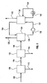
- FIG. 1 is a schematic representation of the integrated system to capture residual
- the system includes gas cleaning, CO2 absorption and CO2 regeneration.
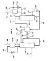
- FIG. 2 is a schematic of the subsystems for the cooling of the gas and for deep cleaning of residual contaminants.
- FIG. 3 is a schematic of the CO 2 capture and regeneration subsystems. It includes CO 2 absorber which operates at low temperature and CO 2 regenerator which operates at moderate temperature and at high pressure.
- a process and system to remove most contaminants, including CO 2 , from gas streams is provided.
- gases are typically resulting from the combustion or gasification of coal, liquid fuels, gaseous fuels and organic waste materials.
- the contaminants include residual of e.g. S02, SO3, HCl, HF, CO 2 , particulate matter including PM2.5, mercury and other volatile matter.
- the high removal efficiency of the contaminants is achieved by saturation and efficient cooling of the gas to below its adiabatic saturation temperature as low as 0-20, or even 0-10, degrees Celsius. Fine particles and acid mist are nucleation sites for the condensation of water. Thus, practically all fine particles and acid mist are removed from the gas stream.
- the low temperature creates an environment of low vapor pressure of S02, S03, HC1, HF, Mercury and other volatile matter, which condense into the cold water as well.
- the cooling of the flue gas enables the efficient capture of CO 2 in CO 2 -lean ammoniated solution or slurry.
- Absorption of the CO 2 is achieved at low temperature at as low as 0-20 degrees Celsius or at as low as 0-10 degrees Celsius.
- the absorbent is regenerated by elevating the temperature of the solution or slurry to the range of 50-200 degrees Celsius (not according to the invention) or in the range of 100-150 degrees Celsius and to pressures in the range of 2 to 138 bar (30-2000 psi).
- the low temperature of absorption and the high pressure of regeneration result in high CO 2 capture efficiency, low energy consumption and low loss of ammonia through evaporation.
- the CO 2 absorption takes place in the aqueous NH 3 -CO 2 -H 2 O system where the ammonia can be in the form of ammonium ion, NH 4 + , or in the form of dissolved molecular NH 3 .
- the capacity of the solution to absorb CO 2 and the form in which the species are present depends on the ammonia concentration, on the NH 3 /CO 2 mole ratio and on the temperature and pressure.
- High NH 3 /CO 2 mole ratio increases the vapor pressure of ammonia and results in ammonia losses through evaporation.
- Low NH 3 /CO 2 ratio increases the vapor pressure of CO 2 and decreases its capture efficiency.
- the optimal NH 3 /CO 2 mole ratio for absorption is in the range of 1.0-4.0 and preferably in the range of 1.5 to 3.0.
- High temperature increases the vapor pressure of both ammonia and CO 2 .
- the absorber should operate at the lowest practical temperature and preferably in the 0-20 degrees Celsius temperature range or even in the 0-10 degrees Celsius temperature range.
- solids particles precipitate. These solids particles are typically in the form of ammonium carbonate (NH 4 ) 2 CO 3 for high NH 3 /CO 2 ratio and ammonium bicarbonate NH 4 HCO 3 for low NH 3 /CO 2 ratio.
- NH 4 ammonium carbonate
- FIG.1 is a schematic representation of the integrated process, which includes cleaning and cooling of the gas, CO 2 absorption into CO 2 -lean ammoniated solution and CO 2 regeneration from the CO 2 -rich solution.
- Stream 102 is a gas stream from combustion or industrial process containing residual contaminants, CO 2 and inert gas species. The CO 2 concentration of the gas is typically 10-15% for coal combustion and 3-4% for natural gas combustion.
- Subsystem 130 represents a series of conventional air pollution control processes which, depending on the source of the gas may include particulate collectors, NO. and S02 control, acid mist capturing device and more. The contaminants collected in the system are removed in stream 112.
- Stream 104 downstream of the conventional 'cleaning devices, contains residual contaminants not collected by the conventional systems.
- Subsystem 132 is a series of one or more Direct Contact Coolers (DCC), where cold water generated in cooling towers and chillers (not shown) is used to wash and scrub the gas, capture its residual contaminants and lower its moisture content.
- Stream 114 is a bleed from subsystem 132 designed to purge all the residual contaminants captured.
- DCC Direct Contact Coolers
- Stream 106 is a cooled gas suitable for CO2 capture in the CO2 absorber.
- Subsystem 134 represents the CO2 absorber and may comprise of a series of absorber stages, depending on the removal efficiency required and the operating conditions of the plant.
- the clean gas with low CO2 concentration, stream 108, is released to the atmosphere.
- Stream 124 is a cooled CO2-lean ammoniated solution from the regenerator, subsystem 136, which is used as the absorbent to capture the CO2 in the absorber.
- the resultant stream 120 is a CO2-rich ammoniated solution sent for regeneration.
- the regenerator, subsystem 136 operates at high pressure and elevated temperature and may be a single or a series of regeneration reactors.
- the pressure of the ammoniated solution fed to the regenerator is elevated using high pressure pump 138, to yield stream 122 which is CO2-rich and at high pressure.
- the pressure of stream 122 is in the range of 4-172 bar (50-2500 psi), higher than the regenerator pressure to prevent premature evaporation of CO2.
- Heat is provided to the regenerator by heating stream 126 in heater 140.
- the high pressure and high temperature in the regenerator cause the release of high-pressure gaseous CO 2 , stream 110.
- the high-pressure regeneration has major cost and energy advantage. Low quality thermal energy is used to generate the high pressure CO 2 stream instead of high-value electric power.
- FIG. 2 is a schematic representation of the cooling and cleaning subsystems, which may optionally include waste heat recovery, heat exchanger 240 , for utilization of the residual heat in the gas.
- the residual heat in stream 202 can be extracted in heat exchanger 240 by transferring of the heat to a cooling medium streams 220 and 222. The heat can then be used downstream for CO2 regeneration.
- Vessel 242 is a wet direct contact scrubber used to adiabatically cool and saturate the gas. If the gas contains high concentration of acid species, such as gas from coal or oil fired power plants, then reactor 242 is used for flue gas desulfurization. Acid absorbing reagent, such as limestone, stream 226, is added to vessel 242 and the product, such as gypsum, stream 224, is withdrawn. Make up water, stream 227, is added to vessel 242 from the Direct Contact Cooler (DCC) 244. The make up stream contains all the contaminants collected in the direct contact coolers. These contaminants are removed from the system with the discharge stream 224. Gas stream 202 in coal fired boiler is typically at temperature in the range of 100-200 degrees Celsius, gas stream 204 is typically at temperature range of 80-100 degrees Celsius and gas stream 206 is typically water-saturated and at temperature range of 40-70 degrees Celsius.
- DCC Direct Contact Cooler
- FIG. 2 Two stages of direct contact cooling and cleaning, vessels 244 and 246, are shown in FIG. 2 .
- the actual number of direct contact coolers may be higher and it depends on optimization between capital cost, energy efficiency and cleaning efficiency requirements.
- Gas stream 206 is cooled in DCC 244 to just above the cooling water temperature of stream 230 .
- the temperature of the cooling water, stream 230 depends on the ambient conditions and on the operation and process conditions of Cooling Tower 250.
- Cooling Tower 250 can be of the wet type with temperature slightly below or slightly above ambient temperature, or the dry type with temperature above ambient temperature.
- Ambient air, Stream 212 provides the heat sink for the system and the heat is rejected in Stream 214 , which absorbs the heat from water stream 228 .
- the resultant cooled water stream 230 is typically at temperature range of 25-40 degrees Celsius and the resultant cooled combustion gas stream from DCC 244 is at about 1-3 degrees Celsius higher temperature.
- Alkaline materials such as ammonium or sodium carbonate can be added to DCC 244 to neutralize the acidic species captured. The alkaline materials can be added in makeup water, stream 225.
- Stream 208 flows to DCC 246 , which is similar to DCC 244 except for the fact that colder water, stream 234 , is used for cooling.
- Stream 234 is a chilled water stream cooled by Chiller 248 , which is preferably a mechanical vapor compression machine with water as its refrigerant. Heat from Chiller 248 is rejected via stream 236 to Cooling Tower 250 with returning stream 238 .
- Cooling water stream 234 can be as cold as 0-3 degrees Celsius or higher resulting in combustion gas temperature, stream 210, exiting DCC 246 being at 0-10 degrees Celsius temperature or few degrees higher.
- the heat absorbed from the gas stream is removed from DCC 246 via water stream 232. More condensation occurs in DCC 246 and further capture of contaminants. These contaminants are bled from the system to vessel 242 . (Bleed stream is not shown).
- Gas Stream 210 the product of the cooling and cleaning subsystem shown in FIG. 2 , is at low temperature; it contains low moisture and practically has no particulate matter, acidic or volatile species.
- FIG. 3 is a schematic representation of the CO2 capture and regeneration subsystem.
- Stream 302 is a clean and cooled gas stream, similar to stream 210 in FIG. 2 . It flows into the CO2 absorber 350, where the CO2 is absorbed by a cooled CO2-lean ammoniated solution or slurry, Stream 324 containing NH3/CO2 mole ratio in the range of 1.5-4.0 and preferably 1.5-3.0. Depending on the absorber design and the number of absorption stages used, more than 90% of the CO2 in Stream 302 can be captured to yield a cold and CO2 depleted gas stream 304. Residual ammonia in stream 304 can be washed in vessel 356 by cold water or by cold and slightly acidic solution, stream 338. Stream 338 is cooled in heat exchanger 368. As a result of the cooling, cleaning and CO2 capture, the gas stream discharged from the system, Stream 306, contains mainly nitrogen, oxygen and low concentration of CO2 and H20.
- Stream 324 is a CO2-lean stream from the regenerator, which is cooled in the regenerative heat exchanger 354 and further by chilled water in heat exchanger 362. It captures CO2 in absorber 350 and discharges from the absorber, Stream 312, as a CO2-rich stream with NH3/CO2 mole ratio in the range of 1.0-2.0 and preferably with NH3/CO2 mole ratio in the range of 1.0-1.5.
- stream 312 contains high concentration of dissolved and suspended ammonium bicarbonate. A portion of stream 312 is optionally recycled back to the absorber while the balance, Stream 314, is pressurized in high pressure pump 360 to yield high pressure ammoniated solution stream 316.
- Stream 316 is heated in regenerative heat exchanger 354, by exchanging heat with the hot and CO2-lean stream from the regenerator, stream 322, which is a portion of stream 320 discharged at the bottom of regenerator 352.
- the CO 2 -rich stream from the regenerative heat exchanger 354, stream 318 can be further heated with waste heat from the boiler or from other sources. It flows into the regenerator 352, which has one or more stages of regeneration. More heat is provided to the regenerator from heat exchanger 364, which heats stream 330.
- the heat provided to the system from the various sources elevates the regenerator temperature to 50-150 degrees Celsius or higher, depending on the desired pressure of the CO 2 stream 308 and subject to cost optimization consideration. The higher the temperature the higher will be the pressure of the CO 2 that evolves from the solution, stream 308. The higher the pressure the lower will be the ammonia and water vapor content of stream 308.
- stream 308 is washed and cooled in direct contact vessel 358 with cold water, stream 336 from heat exchanger 366. Excess water and NH3 captured in vessel 358, stream 332, flows back to regenerator 352 while the balance, stream 334, is cooled and recycled to the wash chamber, vessel 358.
Priority Applications (1)
| Application Number | Priority Date | Filing Date | Title |
|---|---|---|---|
| PL05735524T PL1781400T3 (pl) | 2004-08-06 | 2005-04-12 | Oczyszczanie spalin obejmujące usuwanie CO2 |
Applications Claiming Priority (3)
| Application Number | Priority Date | Filing Date | Title |
|---|---|---|---|
| US59922804P | 2004-08-06 | 2004-08-06 | |
| US61777904P | 2004-10-13 | 2004-10-13 | |
| PCT/US2005/012794 WO2006022885A1 (en) | 2004-08-06 | 2005-04-12 | Ultra cleaning of combustion gas including the removal of co2 |
Publications (3)
| Publication Number | Publication Date |
|---|---|
| EP1781400A1 EP1781400A1 (en) | 2007-05-09 |
| EP1781400A4 EP1781400A4 (en) | 2009-07-15 |
| EP1781400B1 true EP1781400B1 (en) | 2013-07-03 |
Family
ID=35967823
Family Applications (1)
| Application Number | Title | Priority Date | Filing Date |
|---|---|---|---|
| EP05735524.0A Active EP1781400B1 (en) | 2004-08-06 | 2005-04-12 | Cleaning of combustion gas including the removal of co2 |
Country Status (14)
| Country | Link |
|---|---|
| US (2) | US7641717B2 (ko) |
| EP (1) | EP1781400B1 (ko) |
| JP (1) | JP4995084B2 (ko) |
| KR (1) | KR100869665B1 (ko) |
| AU (1) | AU2005278126B2 (ko) |
| BR (1) | BRPI0514141A (ko) |
| CA (1) | CA2574633C (ko) |
| DK (1) | DK1781400T3 (ko) |
| IL (1) | IL180614A (ko) |
| MX (1) | MX2007001367A (ko) |
| NO (1) | NO335509B1 (ko) |
| PL (1) | PL1781400T3 (ko) |
| RU (1) | RU2378040C2 (ko) |
| WO (1) | WO2006022885A1 (ko) |
Families Citing this family (171)
| Publication number | Priority date | Publication date | Assignee | Title |
|---|---|---|---|---|
| BRPI0514141A (pt) * | 2004-08-06 | 2008-05-27 | Eig Inc | ultralimpeza de gás de combustão incluindo a remoção de co2 |
| WO2007012143A1 (en) * | 2005-07-29 | 2007-02-01 | Commonwealth Scientific And Industrial Research Organisation | Recovery of carbon dioxide from flue gases |
| DE102005050385A1 (de) | 2005-10-20 | 2007-04-26 | Basf Ag | Absorptionsmittel und Verfahren zum Entfernen von Kohlendioxid aus Gasströmen |
| PE20071048A1 (es) | 2005-12-12 | 2007-10-18 | Basf Ag | Proceso para la recuperacion de dioxido de carbono |
| ES2358517T3 (es) * | 2005-12-16 | 2011-05-11 | Evonik Energy Services Gmbh | Procedimiento de tratamiento de catalizadores de gas de humo. |
| JP2009530073A (ja) | 2006-03-16 | 2009-08-27 | ビーエーエスエフ ソシエタス・ヨーロピア | 二相の接点が熱発生を随伴している二相を接触させる方法 |
| AU2007253430B2 (en) | 2006-05-18 | 2011-03-10 | Basf Se | Carbon dioxide absorbent requiring less regeneration energy |
| NO333144B1 (no) * | 2006-11-24 | 2013-03-18 | Aker Clean Carbon As | Fremgangsmåte og regenerator for regenerering av absorbent som har absorbert CO2 |
| PL2117683T3 (pl) | 2006-12-15 | 2013-08-30 | Sinvent As | Sposób wychwytywania CO<sub>2</sub> z gazów odlotowych/spalinowych |
| GB2458434B (en) | 2007-01-19 | 2012-01-11 | Exxonmobil Upstream Res Co | Integrated controlled freeze zone (CFZ) tower and dividing wall (DWC) for enhanced hydrocarbon recovery |
| US7867322B2 (en) | 2007-01-31 | 2011-01-11 | Alstom Technology Ltd | Use of SO2 from flue gas for acid wash of ammonia |
| KR100836709B1 (ko) * | 2007-02-02 | 2008-06-10 | 한국에너지기술연구원 | 암모니아수를 이용하여 혼합가스에서 이산화탄소를회수하면서 암모니아 손실을 방지하는 방법 및 장치 |
| WO2008101293A1 (en) | 2007-02-20 | 2008-08-28 | Hunwick Richard J | System, apparatus and method for carbon dioxide sequestration |
| CA2685040A1 (en) * | 2007-05-01 | 2008-11-06 | Powerspan Corp. | Removal of carbon dioxide from flue gas streams using mixed ammonium/alkali solutions |
| DE102007020855A1 (de) * | 2007-05-02 | 2008-11-06 | Evonik Energy Services Gmbh | Verfahren zum Reinigen von Rauchgasen aus Verbrennungsanlagen |
| US8398743B2 (en) | 2007-05-08 | 2013-03-19 | General Electric Company | Methods and systems for reducing carbon dioxide in combustion flue gases |
| CA2686060A1 (en) * | 2007-05-09 | 2008-11-20 | Powerspan Corp. | Carbon dioxide scrubbing with ammonium carbonate and ammonia vapor control |
| US9174161B2 (en) * | 2007-05-24 | 2015-11-03 | Co2 Purification As | Process for removal of carbon dioxide from combustion gases |
| US7981196B2 (en) * | 2007-06-04 | 2011-07-19 | Posco | Apparatus and method for recovering carbon dioxide from flue gas using ammonia water |
| PL2175967T3 (pl) * | 2007-06-22 | 2015-09-30 | Commw Scient Ind Res Org | Usprawniona metoda przenoszenia CO2 ze strumieni gazu do roztworów amoniaku |
| EP2014347A1 (en) * | 2007-07-03 | 2009-01-14 | ALSTOM Technology Ltd | Removal of carbon dioxide from flue gas |
| CA2693466A1 (en) * | 2007-07-12 | 2009-01-15 | Powerspan Corp. | Scrubbing of ammonia with urea ammonium nitrate solution |
| US8182577B2 (en) * | 2007-10-22 | 2012-05-22 | Alstom Technology Ltd | Multi-stage CO2 removal system and method for processing a flue gas stream |
| GB0721488D0 (en) * | 2007-11-01 | 2007-12-12 | Alstom Technology Ltd | Carbon capture system |
| WO2009061470A1 (en) | 2007-11-08 | 2009-05-14 | The University Of Akron | Amine absorber for carbon dioxide capture and processes for making and using the same |
| CA2703998C (en) * | 2007-11-15 | 2016-07-05 | Basf Se | Method for removing carbon dioxide from fluid flows, in particular combustion exhaust gases |
| WO2009068594A1 (en) * | 2007-11-29 | 2009-06-04 | Shell Internationale Research Maatschappij B.V. | Process for removal of carbon dioxide from flue gas with ammonia cooled by vaporised liquefied natural gas |
| US7862788B2 (en) * | 2007-12-05 | 2011-01-04 | Alstom Technology Ltd | Promoter enhanced chilled ammonia based system and method for removal of CO2 from flue gas stream |
| FR2924951A1 (fr) * | 2007-12-12 | 2009-06-19 | Air Liquide | Procede de co- ou tri-generation avec mise en oeuvre d'une premiere et d'une seconde unites de capture de h2s et/ou du co2 fonctionnant en parallele. |
| US8192530B2 (en) * | 2007-12-13 | 2012-06-05 | Alstom Technology Ltd | System and method for regeneration of an absorbent solution |
| US20110052453A1 (en) * | 2008-01-18 | 2011-03-03 | Mclarnon Christopher | Removal of carbon dioxide from a flue gas stream |
| US8343445B2 (en) | 2008-03-21 | 2013-01-01 | Alstom Technology Ltd | System and method for enhanced removal of CO2 from a mixed gas stream |
| US8414853B2 (en) | 2008-03-21 | 2013-04-09 | Alstom Technology Ltd | System and method for enhanced removal of CO2 from a mixed gas stream via use of a catalyst |
| US20090282977A1 (en) * | 2008-05-14 | 2009-11-19 | Alstom Technology Ltd | Gas purification system having provisions for co2 injection of wash water |
| MY153854A (en) * | 2008-06-19 | 2015-03-31 | Shell Int Research | Process for the removal of carbon dioxide from a gas |
| AU2009268911A1 (en) * | 2008-07-10 | 2010-01-14 | Shell Internationale Research Maatschappij B.V. | Method of treating natural gas with high carbon dioxide concentration using aqueous ammonia |
| WO2010020017A1 (en) * | 2008-08-22 | 2010-02-25 | Commonwealth Scientific And Industrial Research Organisation | Treatment of co2-depleted flue gases |
| US7846240B2 (en) | 2008-10-02 | 2010-12-07 | Alstom Technology Ltd | Chilled ammonia based CO2 capture system with water wash system |
| DE102008050816B4 (de) * | 2008-10-08 | 2013-09-05 | Alstom Technology Ltd. | Verfahren und Anordnung zur Abscheidung von CO2 aus Verbrennungsabgas |
| DE102008052612A1 (de) * | 2008-10-21 | 2010-04-22 | Uhde Gmbh | Waschlösung zur Gaswäsche mit Aminen in wässrige Ammoniaklösung sowie Verwendung |
| US8404027B2 (en) * | 2008-11-04 | 2013-03-26 | Alstom Technology Ltd | Reabsorber for ammonia stripper offgas |
| FR2940413B1 (fr) * | 2008-12-19 | 2013-01-11 | Air Liquide | Procede de capture du co2 par cryo-condensation |
| WO2010081007A2 (en) * | 2009-01-09 | 2010-07-15 | Codexis, Inc. | Carbonic anhydrase polypeptides and uses thereof |
| DK2230000T3 (da) | 2009-03-12 | 2013-09-08 | Alstom Technology Ltd | Røggasbehandlingssystem og fremgangsmåde ved anvendelse af ammoniakopløsning |
| JP5478921B2 (ja) * | 2009-03-26 | 2014-04-23 | バブコック日立株式会社 | 排煙処理装置と方法 |
| WO2010110939A1 (en) * | 2009-03-27 | 2010-09-30 | Alstom Technology Ltd | Gas stream processing |
| US8292989B2 (en) * | 2009-10-30 | 2012-10-23 | Alstom Technology Ltd | Gas stream processing |
| US8845789B2 (en) * | 2009-03-31 | 2014-09-30 | Alstom Technology Ltd | Process for CO2 capture with improved stripper performance |
| US9423174B2 (en) | 2009-04-20 | 2016-08-23 | Exxonmobil Upstream Research Company | Cryogenic system for removing acid gases from a hydrocarbon gas stream, and method of removing acid gases |
| US8795405B1 (en) * | 2009-06-08 | 2014-08-05 | Shaw Intellectual Property Holdings, Llc | Beneficial use of carbon |
| AU2010261784B2 (en) | 2009-06-19 | 2014-01-23 | Shell Internationale Research Maatschappij B.V. | Process for the removal of carbon dioxide and/or hydrogen sulphide from a gas |
| CA2771566C (en) | 2009-09-09 | 2017-07-18 | Exxonmobil Upstream Research Company | Cryogenic system for removing acid gases from a hydrocarbon gas stream |
| US8309047B2 (en) | 2009-09-15 | 2012-11-13 | Alstom Technology Ltd | Method and system for removal of carbon dioxide from a process gas |
| US8790605B2 (en) * | 2009-09-15 | 2014-07-29 | Alstom Technology Ltd | Method for removal of carbon dioxide from a process gas |
| US8784761B2 (en) * | 2009-11-20 | 2014-07-22 | Alstom Technology Ltd | Single absorber vessel to capture CO2 |
| US8518156B2 (en) * | 2009-09-21 | 2013-08-27 | Alstom Technology Ltd | Method and system for regenerating a solution used in a wash vessel |
| US20110068585A1 (en) * | 2009-09-24 | 2011-03-24 | Alstom Technology Ltd | Method and system for capturing and utilizing energy generated in a flue gas stream processing system |
| US20110085955A1 (en) * | 2009-10-12 | 2011-04-14 | Alstom Technology Ltd | System and method for reducing no2 poisoning |
| EP2311545A1 (en) * | 2009-10-15 | 2011-04-20 | Nederlandse Organisatie voor toegepast -natuurwetenschappelijk onderzoek TNO | Method for absorption of acid gases |
| AU2010319846B2 (en) | 2009-10-28 | 2015-05-28 | Oasys Water LLC | Forward osmosis separation processes |
| US9044711B2 (en) | 2009-10-28 | 2015-06-02 | Oasys Water, Inc. | Osmotically driven membrane processes and systems and methods for draw solute recovery |
| EP2322265A1 (en) * | 2009-11-12 | 2011-05-18 | Alstom Technology Ltd | Flue gas treatment system |
| US8460436B2 (en) | 2009-11-24 | 2013-06-11 | Alstom Technology Ltd | Advanced intercooling and recycling in CO2 absorption |
| EP2335806A1 (en) * | 2009-12-04 | 2011-06-22 | Alstom Technology Ltd | Method and system for condensing water vapour from a carbon dioxide rich flue gas |
| ES2523442T3 (es) * | 2009-12-04 | 2014-11-26 | Alstom Technology Ltd | Método y dispositivo para purificar un gas de chimenea rico en dióxido de carbono |
| US8734569B2 (en) | 2009-12-15 | 2014-05-27 | L'air Liquide, Societe Anonyme Pour L'etude Et L'exploitation Des Procedes Georges Claude | Method of obtaining carbon dioxide from carbon dioxide-containing gas mixture |
| US8617292B2 (en) | 2009-12-15 | 2013-12-31 | L'Air Liquide, Société Anonyme pour l'Etude et l'Exploitation des Procédés Georges Claude | Method of obtaining carbon dioxide from carbon dioxide-containing gas mixture |
| US8663364B2 (en) | 2009-12-15 | 2014-03-04 | L'Air Liquide, Société Anonyme pour l'Étude et l'Éxploitation des Procédés Georges Claude | Method of obtaining carbon dioxide from carbon dioxide-containing gas mixture |
| US8293200B2 (en) | 2009-12-17 | 2012-10-23 | Alstom Technology Ltd | Desulfurization of, and removal of carbon dioxide from, gas mixtures |
| US20110146489A1 (en) | 2009-12-17 | 2011-06-23 | Alstom Technology Ltd | Ammonia removal, following removal of co2, from a gas stream |
| US20110173981A1 (en) * | 2010-01-15 | 2011-07-21 | Alstom Technology Ltd. | Utilization of low grade heat in a refrigeration cycle |
| EP2360296B1 (en) | 2010-01-21 | 2017-03-15 | General Electric Technology GmbH | A method of ventilating an aluminium production electrolytic cell |
| WO2011090553A1 (en) | 2010-01-22 | 2011-07-28 | Exxonmobil Upstream Research Company | Removal of acid gases from a gas stream, with co2 capture and sequestration |
| SG182399A1 (en) | 2010-02-03 | 2012-08-30 | Exxonmobil Upstream Res Co | Systems and methods for using cold liquid to remove solidifiable gas components from process gas streams |
| CA2788978A1 (en) * | 2010-02-19 | 2011-08-25 | Phil Jackson | Vapour suppression additive |
| JPWO2011152547A1 (ja) | 2010-05-31 | 2013-08-01 | 三菱重工業株式会社 | 排ガス処理システム及び方法 |
| AU2011259877B2 (en) | 2010-05-31 | 2014-09-18 | Mitsubishi Heavy Industries, Ltd. | Exhaust gas treatment system and method |
| US8894941B2 (en) | 2010-05-31 | 2014-11-25 | Mitsubishi Heavy Industries, Ltd. | Air pollution control system and method |
| JPWO2011152548A1 (ja) | 2010-05-31 | 2013-08-01 | 三菱重工業株式会社 | 排ガス処理システム及び方法 |
| US8512445B2 (en) * | 2010-06-23 | 2013-08-20 | Shiaoguo Chen | Carbonate absorption system and process for carbon dioxide separation |
| US8354261B2 (en) | 2010-06-30 | 2013-01-15 | Codexis, Inc. | Highly stable β-class carbonic anhydrases useful in carbon capture systems |
| WO2012003299A2 (en) | 2010-06-30 | 2012-01-05 | Codexis, Inc. | Highly stable beta-class carbonic anhydrases useful in carbon capture systems |
| EP2588597A4 (en) | 2010-06-30 | 2013-12-25 | Codexis Inc | CHEMICALLY MODIFIED CARBOHYDRED ANHYDRASES SUITABLE FOR CARBON STORAGE SYSTEMS |
| KR101217258B1 (ko) * | 2010-07-01 | 2012-12-31 | 성호그린테크주식회사 | 가스정화장치 및 정화방법 |
| US7993615B1 (en) * | 2010-07-06 | 2011-08-09 | Babcock & Wilcox Power Generation Group, Inc. | Integrated flue gas dehumidification and wet cooling tower system |
| EP2590898B1 (en) | 2010-07-09 | 2020-12-09 | Arnold Keller | Carbon dioxide capture and liquefaction |
| US8518148B2 (en) | 2010-07-12 | 2013-08-27 | Babcock & Wilcox Power Generation Group, Inc. | Integrated flue gas dehumidification and wet cooling tower system |
| MX362706B (es) | 2010-07-30 | 2019-02-01 | Exxonmobil Upstream Res Company Star | Sistemas criogenicos para remover gases acidos de una corriente de gas de hidrocarburo que usan dispositivos de separacion de co-corriente. |
| US9427697B2 (en) | 2010-07-30 | 2016-08-30 | General Electric Company | Methods and systems for CO2 separation |
| AU2011296309B2 (en) | 2010-09-02 | 2014-11-20 | The Regents Of The University Of California | Method and system for capturing carbon dioxide and/or sulfur dioxide from gas stream |
| US8728209B2 (en) | 2010-09-13 | 2014-05-20 | Alstom Technology Ltd | Method and system for reducing energy requirements of a CO2 capture system |
| US8623307B2 (en) | 2010-09-14 | 2014-01-07 | Alstom Technology Ltd. | Process gas treatment system |
| EP2431499B1 (en) | 2010-09-17 | 2014-04-23 | Alstom Technology Ltd | Raw gas collection system |
| EP2433700A1 (en) | 2010-09-23 | 2012-03-28 | Alstom Technology Ltd | Trace component removal in CO2 removal processes by means of a semipermeable membrane |
| US8940261B2 (en) | 2010-09-30 | 2015-01-27 | The University Of Kentucky Research Foundation | Contaminant-tolerant solvent and stripping chemical and process for using same for carbon capture from combustion gases |
| EP2627434A4 (en) * | 2010-10-12 | 2014-12-24 | Gtlpetrol Llc | CARBON DIOXIDE DEPOSITION FROM HIGH PRESSURE STREAMS |
| US20120129113A1 (en) | 2010-11-22 | 2012-05-24 | Alstom Technology Ltd. | System and method of managing energy utilized in a flue gas processing system |
| US20120125240A1 (en) | 2010-11-22 | 2012-05-24 | Alstom Technology Ltd. | System and method of managing energy utilized in a flue gas processing system |
| KR101527452B1 (ko) * | 2010-12-27 | 2015-06-12 | 재단법인 포항산업과학연구원 | 탄산 세정수를 이용한 암모니아의 슬립 억제방법 |
| EP2481470A1 (en) | 2011-02-01 | 2012-08-01 | ALSTOM Technology Ltd | Process gas treatment system |
| US8329128B2 (en) | 2011-02-01 | 2012-12-11 | Alstom Technology Ltd | Gas treatment process and system |
| US9028784B2 (en) | 2011-02-15 | 2015-05-12 | Alstom Technology Ltd | Process and system for cleaning a gas stream |
| US9133407B2 (en) | 2011-02-25 | 2015-09-15 | Alstom Technology Ltd | Systems and processes for removing volatile degradation products produced in gas purification |
| DE102011015466A1 (de) * | 2011-03-31 | 2012-10-25 | Immoplan Verfahrenstechnik | Ammoniak- und kohlendioxidhaltige Luftreinigung, insbesondere die Luft in Gebäuden mit Tierhaltung bei gleichzeitiger Gewinnung von Ammoniumsalzen. |
| EP2520352B1 (en) | 2011-05-02 | 2021-06-30 | General Electric Technology GmbH | Gas/liquid contacting vessel and the use thereof in a flue gas treatment system |
| US20130064748A1 (en) * | 2011-05-02 | 2013-03-14 | Alstom Technology Ltd | METHOD AND APPARATUS FOR CAPTURING SOx IN A FLUE GAS PROCESSING SYSTEM |
| RU2474703C1 (ru) * | 2011-06-23 | 2013-02-10 | Государственное образовательное учреждение высшего профессионального образования "Самарский государственный университет путей сообщения" (СамГУПС) | Способ комплексной очистки газообразных продуктов сгорания |
| US8623314B2 (en) * | 2011-07-01 | 2014-01-07 | Alstom Technology Ltd | Chilled ammonia based CO2 capture system with ammonia recovery and processes of use |
| US8864878B2 (en) | 2011-09-23 | 2014-10-21 | Alstom Technology Ltd | Heat integration of a cement manufacturing plant with an absorption based carbon dioxide capture process |
| US9901861B2 (en) | 2011-10-18 | 2018-02-27 | General Electric Technology Gmbh | Chilled ammonia based CO2 capture system with wash system and processes of use |
| US8470077B2 (en) | 2011-11-17 | 2013-06-25 | Alstom Technology Ltd | Low pressure stripping in a gas purification process and systems thereof |
| US9492786B2 (en) | 2011-11-22 | 2016-11-15 | Fluor Corporation | Multi-purpose absorber |
| US8911538B2 (en) | 2011-12-22 | 2014-12-16 | Alstom Technology Ltd | Method and system for treating an effluent stream generated by a carbon capture system |
| NO2617708T3 (ko) | 2012-01-17 | 2018-01-13 | ||
| US20130183218A1 (en) | 2012-01-18 | 2013-07-18 | Rameshwar S. Hiwale | Control of a chilled ammonia process |
| US9162177B2 (en) | 2012-01-25 | 2015-10-20 | Alstom Technology Ltd | Ammonia capturing by CO2 product liquid in water wash liquid |
| US9028654B2 (en) | 2012-02-29 | 2015-05-12 | Alstom Technology Ltd | Method of treatment of amine waste water and a system for accomplishing the same |
| WO2013142100A1 (en) | 2012-03-21 | 2013-09-26 | Exxonmobil Upstream Research Company | Separating carbon dioxide and ethane from a mixed stream |
| US20130259781A1 (en) * | 2012-03-30 | 2013-10-03 | Alstom Technology Ltd | Flue gas treatment system with ammonia solvent for capture of carbon dioxide |
| US8864879B2 (en) * | 2012-03-30 | 2014-10-21 | Jalal Askander | System for recovery of ammonia from lean solution in a chilled ammonia process utilizing residual flue gas |
| EP2653210A1 (de) * | 2012-04-18 | 2013-10-23 | Siemens Aktiengesellschaft | Verbrennungsanlage mit Rauchgaswascher und CO2-Abscheidung sowie Verfahren zu deren Betrieb |
| WO2013159215A1 (en) * | 2012-04-24 | 2013-10-31 | Co2 Solutions Inc. | Co2 capture using low concentration ammonia based absorption solutions in presence of enzymes |
| US9234286B2 (en) | 2012-05-04 | 2016-01-12 | Alstom Technology Ltd | Recycled pot gas pot distribution |
| CN102818783B (zh) * | 2012-09-07 | 2015-03-18 | 武汉钢铁(集团)公司 | 烧结烟气氨法脱硫工艺中氨逃逸量的测定方法及其装置 |
| DE102012020141A1 (de) | 2012-10-15 | 2014-04-17 | Hermann Büttner | Verfahren zur synchronen Absorption von Kohlenstoffdioxid aus Rauchgas und Synthese von Dialkylcarbonaten und Alkylencarbonaten |
| EP2724770A1 (en) | 2012-10-26 | 2014-04-30 | Alstom Technology Ltd | Absorption unit for drying flue gas |
| US9101912B2 (en) | 2012-11-05 | 2015-08-11 | Alstom Technology Ltd | Method for regeneration of solid amine CO2 capture beds |
| EP2754480B1 (en) | 2013-01-09 | 2022-05-11 | General Electric Technology GmbH | Flue gas treatment method and system for removal of carbon dioxide, sulfure dioxide, particulate material and heavy metals |
| US9447996B2 (en) | 2013-01-15 | 2016-09-20 | General Electric Technology Gmbh | Carbon dioxide removal system using absorption refrigeration |
| US9428449B2 (en) | 2013-01-16 | 2016-08-30 | Alstom Technology Ltd | Method of forming urea by integration of an ammonia production process in a urea production process and a system therefor |
| EP2757071B1 (en) * | 2013-01-17 | 2018-05-02 | General Electric Technology GmbH | Integrated carbon dioxide removal and ammonia-soda process |
| US9623366B2 (en) | 2013-03-04 | 2017-04-18 | Mitsubishi Heavy Industries, Ltd. | CO2 recovery system and CO2 recovery method |
| US9192888B2 (en) * | 2013-06-26 | 2015-11-24 | Uop Llc | Apparatuses and methods for removing acid gas from sour gas |
| CN104338421A (zh) * | 2013-07-28 | 2015-02-11 | 江苏凯伦建材股份有限公司 | 一种防水卷材生产废气净化装置 |
| WO2015051400A1 (en) * | 2013-10-07 | 2015-04-16 | Reid Systems (Australia) Tpy Ltd | Method and apparatus for removing carbon dioxide from flue gas |
| WO2015084495A2 (en) | 2013-12-06 | 2015-06-11 | Exxonmobil Upstream Research Company | Method and system of maintaining a liquid level in a distillation tower |
| CA2925404C (en) | 2013-12-06 | 2018-02-06 | Exxonmobil Upstream Research Company | Method and system of dehydrating a feed stream processed in a distillation tower |
| CA2924402C (en) | 2013-12-06 | 2017-11-21 | Exxonmobil Upstream Research Company | Method and device for separating a feed stream using radiation detectors |
| US9562719B2 (en) | 2013-12-06 | 2017-02-07 | Exxonmobil Upstream Research Company | Method of removing solids by modifying a liquid level in a distillation tower |
| CA2931409C (en) | 2013-12-06 | 2017-08-01 | Exxonmobil Upstream Research Company | Method and device for separating hydrocarbons and contaminants with a spray assembly |
| AU2014357667B2 (en) | 2013-12-06 | 2017-10-05 | Exxonmobil Upstream Research Company | Method and system for separating a feed stream with a feed stream distribution mechanism |
| US9874395B2 (en) | 2013-12-06 | 2018-01-23 | Exxonmobil Upstream Research Company | Method and system for preventing accumulation of solids in a distillation tower |
| US9874396B2 (en) | 2013-12-06 | 2018-01-23 | Exxonmobil Upstream Research Company | Method and device for separating hydrocarbons and contaminants with a heating mechanism to destabilize and/or prevent adhesion of solids |
| MY176633A (en) | 2013-12-06 | 2020-08-19 | Exxonmobil Upstream Res Co | Method and system of modifiying a liquid level during start-up operations |
| US8986640B1 (en) | 2014-01-07 | 2015-03-24 | Alstom Technology Ltd | System and method for recovering ammonia from a chilled ammonia process |
| SG11201705162SA (en) | 2015-02-27 | 2017-09-28 | Exxonmobil Upstream Res Co | Reducing refrigeration and dehydration load for a feed stream entering a cryogenic distillation process |
| EP3069781B1 (en) | 2015-03-20 | 2019-05-08 | General Electric Technology GmbH | System for sulphur removal from a flue gas |
| US9573816B2 (en) | 2015-04-02 | 2017-02-21 | General Electric Technology Gmbh | System for low pressure carbon dioxide regeneration in a chilled ammonia process |
| US9598993B2 (en) | 2015-06-19 | 2017-03-21 | Saudi Arabian Oil Company | Integrated process for CO2 capture and use in thermal power production cycle |
| NO341515B1 (en) | 2015-09-08 | 2017-11-27 | Capsol Eop As | Fremgangsmåte og anlegg for CO2 fangst |
| US10365037B2 (en) | 2015-09-18 | 2019-07-30 | Exxonmobil Upstream Research Company | Heating component to reduce solidification in a cryogenic distillation system |
| CA2998466C (en) | 2015-09-24 | 2021-06-29 | Exxonmobil Upstream Research Company | Treatment plant for hydrocarbon gas having variable contaminant levels |
| US10973413B2 (en) * | 2015-10-07 | 2021-04-13 | Fiomet Ventures, Inc. | Advanced compression garments and systems |
| KR101796236B1 (ko) * | 2015-11-27 | 2017-11-09 | 주식회사 포스코 | 산성 가스 내 이산화탄소 제거 방법 및 그 장치 |
| EA201892054A1 (ru) | 2016-03-30 | 2019-02-28 | Эксонмобил Апстрим Рисерч Компани | Поступающая из собственных источников пластовая текучая среда для повышения нефтеотдачи |
| CN106039755B (zh) * | 2016-07-22 | 2018-03-02 | 京能(锡林郭勒)发电有限公司 | 一种烟气冷凝提水系统 |
| KR101795466B1 (ko) * | 2016-10-31 | 2017-11-10 | 주식회사 포스코 | 가스 처리 방법 및 가스 처리 장치 |
| US20180133647A1 (en) * | 2016-11-15 | 2018-05-17 | 8 Rivers Capital, Llc | Treatment of impurities in process streams |
| PL420590A1 (pl) | 2017-02-21 | 2018-08-27 | Ciech R&D Spolka Z Ograniczona Odpowiedzialnoscia | Sposób ograniczania emisji CO2 w procesach sodowych |
| JP6963393B2 (ja) * | 2017-02-23 | 2021-11-10 | 川崎重工業株式会社 | 二酸化炭素分離回収システム |
| US10427948B2 (en) | 2018-01-26 | 2019-10-01 | Ethan J. Novek | Systems and methods for ammonia recovery, acid gas separation, or combination thereof |
| EP3569301B1 (en) | 2018-05-18 | 2021-12-15 | Reel Alesa AG | Apparatus and method for controlled alumina supply |
| WO2020005552A1 (en) | 2018-06-29 | 2020-01-02 | Exxonmobil Upstream Research Company | Hybrid tray for introducing a low co2 feed stream into a distillation tower |
| WO2020005553A1 (en) | 2018-06-29 | 2020-01-02 | Exxonmobil Upstream Research Company (Emhc-N1.4A.607) | Mixing and heat integration of melt tray liquids in a cryogenic distillation tower |
| GB2584704B (en) | 2019-06-12 | 2023-01-25 | Univ Cranfield | Gas treatment process and gas treatment apparatus |
| US11067335B1 (en) * | 2020-08-26 | 2021-07-20 | Next Carbon Soiittions, Llc | Devices, systems, facilities, and processes for liquefied natural gas production |
| IT202000020473A1 (it) * | 2020-08-26 | 2022-02-26 | Nuovo Pignone Tecnologie Srl | Sistema e metodo di abbattimento di biossido di carbonio a base di ammoniaca, e refrigeratore a contatto diretto per essi |
| TWI789962B (zh) * | 2021-05-05 | 2023-01-11 | 傑智環境科技股份有限公司 | 溫室氣體淨化系統 |
| EP4355461A1 (en) * | 2021-06-15 | 2024-04-24 | Carbon Clean Solutions Limited | Methods and systems for the removal of impurities in a flue gas |
| IT202100018731A1 (it) | 2021-07-15 | 2023-01-15 | Nuovo Pignone Tecnologie Srl | Integrated refrigeration system of a liquefied natural gas production plant comprising a carbon capture unit. |
| US20240035656A1 (en) * | 2022-07-26 | 2024-02-01 | Next Carbon Solutions, Llc | Methods, systems, and devices for flue gas cooling |
Family Cites Families (78)
| Publication number | Priority date | Publication date | Assignee | Title |
|---|---|---|---|---|
| GB271852A (en) | 1926-05-28 | 1927-11-10 | Ig Farbenindustrie Ag | Improvements in and means for the extraction of carbon dioxide from gaseous mixtures |
| BE414069A (ko) * | 1934-12-20 | |||
| US2106734A (en) * | 1935-02-27 | 1938-02-01 | Koppers Co Inc | Gas purification process |
| US2487576A (en) * | 1945-11-13 | 1949-11-08 | Phillips Petroleum Co | Process for the removal of acidic material from a gaseous mixture |
| US2608461A (en) * | 1949-03-26 | 1952-08-26 | Fluor Corp | Prevention of amine losses in gas treating systems |
| US2878099A (en) * | 1955-07-22 | 1959-03-17 | Ruhrstahl Ag Fa | Method of deacidifying gases |
| LU36973A1 (ko) | 1958-03-28 | |||
| GB899611A (en) | 1959-04-15 | 1962-06-27 | Gas Council | Process for separating gases |
| BE617822A (ko) * | 1961-05-19 | |||
| SU512785A1 (ru) | 1970-07-03 | 1976-05-05 | Предприятие П/Я Р-6603 | Способ очистки газа от двуокиси углерода |
| DE2832493A1 (de) | 1978-07-24 | 1980-02-07 | Albert Lammers | Verfahren und vorrichtung zur waermerueckgewinnung und reinigung von abgasen |
| DE3247876A1 (de) * | 1982-12-23 | 1984-06-28 | Linde Ag, 6200 Wiesbaden | Verfahren und vorrichtung zum regulieren des ammoniakgehaltes in der waschfluessigkeit einer gaswaesche |
| US4977745A (en) * | 1983-07-06 | 1990-12-18 | Heichberger Albert N | Method for the recovery of low purity carbon dioxide |
| FR2589142B1 (fr) * | 1985-10-25 | 1988-01-08 | Air Liquide | Procede et installation de production d'anhydride carbonique a partir d'un gaz disponible a une pression voisine de la pression atmospherique |
| DE3614385A1 (de) | 1986-04-28 | 1988-02-04 | Qualmann Horst | Verfahren und vorrichtung zum reinigen von abgasen |
| DE3633690A1 (de) | 1986-10-03 | 1988-04-14 | Linde Ag | Verfahren und vorrichtung zur entfernung von sauren gasen, wie so(pfeil abwaerts)2(pfeil abwaerts), so(pfeil abwaerts)3(pfeil abwaerts), h(pfeil abwaerts)2(pfeil abwaerts)s, co(pfeil abwaerts)2(pfeil abwaerts) und/oder cos, aus heissen gasgemischen |
| SU1567251A1 (ru) | 1987-08-12 | 1990-05-30 | Предприятие П/Я А-3732 | Способ концентрировани диоксида углерода из газов |
| DE3828227A1 (de) * | 1988-08-19 | 1990-02-22 | Basf Ag | Verfahren zum entfernen von co(pfeil abwaerts)2(pfeil abwaerts) und gegebenenfalls h(pfeil abwaerts)2(pfeil abwaerts) aus gasen |
| ZA899705B (en) * | 1989-01-26 | 1990-09-26 | Aeci Ltd | Purification of gases |
| NL8902490A (nl) * | 1989-10-06 | 1991-05-01 | Leonardus Mathijs Marie Nevels | Werkwijze voor het reinigen van rookgassen. |
| NL9002661A (nl) | 1990-12-04 | 1992-07-01 | Pacques Bv | Werkwijze voor de verwijdering van h2s uit gas. |
| DK0502596T4 (da) * | 1991-03-07 | 1999-12-27 | Mitsubishi Heavy Ind Ltd | Apparat og fremgangsmåde til fjernelse af carbondioxid fra forbrændingsafgangsgas |
| US5137550A (en) * | 1991-04-26 | 1992-08-11 | Air Products And Chemicals, Inc. | Cascade acid gas removal process |
| US5378442A (en) * | 1992-01-17 | 1995-01-03 | The Kansai Electric Power Co., Inc. | Method for treating combustion exhaust gas |
| DE4217921A1 (de) * | 1992-05-30 | 1993-12-02 | Huels Chemische Werke Ag | Verfahren zur Rückgewinnung von Ammoniak und organischen Verbindungen aus mit organischen Stoffen, Kohlendioxid und Ammoniak beladenen Abgasen |
| JP2895325B2 (ja) | 1992-09-16 | 1999-05-24 | 関西電力株式会社 | 燃焼排ガス中の二酸化炭素を除去する方法 |
| DE4240196C2 (de) * | 1992-11-30 | 1996-06-13 | Voest Alpine Ind Anlagen | Verfahren zur Kühlung und Reinigung von ultrafeine Partikel enthaltendem Gas, insbesondere Gichtgas oder Generatorgas und Vorrichtung zu seiner Durchführung |
| US5772709A (en) * | 1996-04-18 | 1998-06-30 | Graham Corporatiom | Apparatus for removing ammonia and carbon dioxide gases from a steam |
| TW279137B (en) * | 1993-06-01 | 1996-06-21 | Babcock & Wilcox Co | Method and apparatus for removing acid gases and air toxics from a flue gas |
| JP2912145B2 (ja) * | 1993-11-16 | 1999-06-28 | 住友重機械工業株式会社 | 硫黄酸化物含有ガスの浄化方法 |
| EP0655271A1 (en) | 1993-11-29 | 1995-05-31 | Basf Corporation | Apparatus and process for removing emissions by condensation and precipitation |
| NO180520C (no) * | 1994-02-15 | 1997-05-07 | Kvaerner Asa | Fremgangsmåte til fjerning av karbondioksid fra forbrenningsgasser |
| US5462583A (en) * | 1994-03-04 | 1995-10-31 | Advanced Extraction Technologies, Inc. | Absorption process without external solvent |
| US5511334A (en) * | 1994-10-03 | 1996-04-30 | Henry C. Ball | Lock-action muzzle loader |
| JP3233802B2 (ja) * | 1994-12-15 | 2001-12-04 | 関西電力株式会社 | 燃焼排ガス中の炭酸ガスと窒素酸化物を除去する方法 |
| US5533338A (en) | 1995-03-21 | 1996-07-09 | The Boc Group, Inc. | Cryogenic vapor recovery process and system |
| JP3626796B2 (ja) * | 1995-10-03 | 2005-03-09 | 三菱重工業株式会社 | 高圧天然ガス中の高濃度炭酸ガスを除去する方法 |
| JP3392609B2 (ja) | 1995-12-01 | 2003-03-31 | 三菱重工業株式会社 | ガス中の炭酸ガスを除去する方法 |
| US5700311A (en) * | 1996-04-30 | 1997-12-23 | Spencer; Dwain F. | Methods of selectively separating CO2 from a multicomponent gaseous stream |
| NO302454B1 (no) | 1996-07-31 | 1998-03-09 | Kvaerner Asa | Fremgangsmåte til fjerning av karbondioksid fra gasser |
| DE19635075A1 (de) | 1996-08-30 | 1998-03-05 | Maul & Co Chr Belser Gmbh | Verfahren und Vorrichtung zur Reinigung und Wiederverwendung von Abluft |
| FR2757423B1 (fr) * | 1996-12-19 | 1999-01-29 | Inst Francais Du Petrole | Procede et dispositif de traitement d'un gaz par refrigeration et mise en contact avec un solvant |
| US6077491A (en) * | 1997-03-21 | 2000-06-20 | Ec&C Technologies | Methods for the production of ammonia from urea and/or biuret, and uses for NOx and/or particulate matter removal |
| US6344177B1 (en) | 1997-04-23 | 2002-02-05 | Enviro-Energy Products, Inc. | Heat recovery and pollution abatement device |
| US7022296B1 (en) * | 1997-07-10 | 2006-04-04 | University Of Cincinnati | Method for treating flue gas |
| FR2771022B1 (fr) | 1997-11-19 | 1999-12-17 | Inst Francais Du Petrole | Procede de desacidification d'un gaz a tres forte teneur en gaz acides |
| US6348088B2 (en) * | 1999-01-29 | 2002-02-19 | Taiwan Semiconductor Manufacturing Company, Ltd | System and method for recovering cooling capacity from a factory exhaust gas |
| US6210467B1 (en) * | 1999-05-07 | 2001-04-03 | Praxair Technology, Inc. | Carbon dioxide cleaning system with improved recovery |
| EP1072301B1 (en) * | 1999-07-29 | 2009-11-18 | National Institute Of Advanced Industrial Science and Technology | Method and apparatus for separating and recovering carbon dioxide from combustion exhaust gas |
| JP4370038B2 (ja) | 2000-04-17 | 2009-11-25 | 三菱重工業株式会社 | 排ガス冷却システム |
| US6458188B1 (en) * | 2000-07-14 | 2002-10-01 | Timothy D. Mace | Method and means for air filtration |
| US6497852B2 (en) * | 2000-12-22 | 2002-12-24 | Shrikar Chakravarti | Carbon dioxide recovery at high pressure |
| US6667347B2 (en) | 2001-09-14 | 2003-12-23 | Chevron U.S.A. Inc. | Scrubbing CO2 from methane-containing gases using an aqueous stream |
| US6720359B2 (en) | 2001-09-14 | 2004-04-13 | Chevron U.S.A. Inc. | Scrubbing CO2 from a CO2-containing gas with an aqueous stream |
| AU2003214041B2 (en) | 2002-01-14 | 2008-10-02 | Shell Internationale Research Maatschappij B.V. | Process for removing carbon dioxide from gas mixtures |
| JP3814206B2 (ja) * | 2002-01-31 | 2006-08-23 | 三菱重工業株式会社 | 二酸化炭素回収プロセスの排熱利用方法 |
| WO2003089115A1 (en) | 2002-04-15 | 2003-10-30 | Fluor Corporation | Configurations and methods for improved acid gas removal |
| NL1020560C2 (nl) | 2002-05-08 | 2003-11-11 | Tno | Methode voor absorptie van zure gassen. |
| FI116521B (fi) * | 2002-05-21 | 2005-12-15 | Preseco Oy | Menetelmä eloperäisen materiaalin käsittelemiseksi |
| US6759022B2 (en) * | 2002-06-05 | 2004-07-06 | Marsulex Environmental Technologies | Flue gas desulfurization process and apparatus for removing nitrogen oxides |
| JP4105689B2 (ja) | 2002-07-03 | 2008-06-25 | フルー・コーポレイシヨン | 改良型分流装置 |
| US7101415B2 (en) * | 2002-08-30 | 2006-09-05 | Matheson Tri-Gas, Inc. | Methods for regenerating process gas purifier materials |
| US7424808B2 (en) | 2002-09-17 | 2008-09-16 | Fluor Technologies Corporation | Configurations and methods of acid gas removal |
| ITVE20020030A1 (it) | 2002-10-01 | 2004-04-02 | Valerio Tognazzo | Processo ed impianto per effettuare la ultradepurazione di fumi o gas con recupero totale degli inquinanti di risulta. - |
| ES2365474T3 (es) | 2002-12-12 | 2011-10-06 | Fluor Corporation | Procedimiento de eliminación de gases ácidos. |
| CN100563789C (zh) | 2002-12-17 | 2009-12-02 | 弗劳尔公司 | 接近零排放的去除酸性气和杂质的配置及方法 |
| KR101237667B1 (ko) * | 2003-07-22 | 2013-02-28 | 다우 글로벌 테크놀로지스 엘엘씨 | 산 가스-함유 처리유체의 재생 |
| US7255842B1 (en) * | 2003-09-22 | 2007-08-14 | United States Of America Department Of Energy | Multi-component removal in flue gas by aqua ammonia |
| NO321817B1 (no) * | 2003-11-06 | 2006-07-10 | Sargas As | Renseanlegg for varmekraftverk |
| US7083662B2 (en) * | 2003-12-18 | 2006-08-01 | Air Products And Chemicals, Inc. | Generation of elevated pressure gas mixtures by absorption and stripping |
| FR2863910B1 (fr) * | 2003-12-23 | 2006-01-27 | Inst Francais Du Petrole | Procede de capture du dioxyde de carbone contenu dans des fumees |
| FI20045086A (fi) | 2004-03-18 | 2005-09-19 | Cuycha Innovation Oy | Lähes palautuva prosessi hiilidioksidin erottamiseksi savu- tai tuotekaasusta |
| US7128777B2 (en) * | 2004-06-15 | 2006-10-31 | Spencer Dwain F | Methods and systems for selectively separating CO2 from a multicomponent gaseous stream to produce a high pressure CO2 product |
| BRPI0514141A (pt) * | 2004-08-06 | 2008-05-27 | Eig Inc | ultralimpeza de gás de combustão incluindo a remoção de co2 |
| JP4745682B2 (ja) * | 2005-02-23 | 2011-08-10 | 関西電力株式会社 | Co2回収装置および方法 |
| JP5021917B2 (ja) | 2005-09-01 | 2012-09-12 | 三菱重工業株式会社 | Co2回収装置及び方法 |
| US7867322B2 (en) | 2007-01-31 | 2011-01-11 | Alstom Technology Ltd | Use of SO2 from flue gas for acid wash of ammonia |
| US7846240B2 (en) * | 2008-10-02 | 2010-12-07 | Alstom Technology Ltd | Chilled ammonia based CO2 capture system with water wash system |
-
2005
- 2005-04-12 BR BRPI0514141-9A patent/BRPI0514141A/pt not_active IP Right Cessation
- 2005-04-12 MX MX2007001367A patent/MX2007001367A/es active IP Right Grant
- 2005-04-12 AU AU2005278126A patent/AU2005278126B2/en active Active
- 2005-04-12 EP EP05735524.0A patent/EP1781400B1/en active Active
- 2005-04-12 JP JP2007524786A patent/JP4995084B2/ja active Active
- 2005-04-12 CA CA2574633A patent/CA2574633C/en active Active
- 2005-04-12 DK DK05735524.0T patent/DK1781400T3/da active
- 2005-04-12 PL PL05735524T patent/PL1781400T3/pl unknown
- 2005-04-12 WO PCT/US2005/012794 patent/WO2006022885A1/en active Application Filing
- 2005-04-12 US US11/632,537 patent/US7641717B2/en active Active
- 2005-04-12 KR KR1020077005312A patent/KR100869665B1/ko not_active IP Right Cessation
- 2005-04-12 RU RU2007108285/15A patent/RU2378040C2/ru not_active IP Right Cessation
-
2007
- 2007-01-09 IL IL180614A patent/IL180614A/en not_active IP Right Cessation
- 2007-01-10 NO NO20070165A patent/NO335509B1/no unknown
-
2009
- 2009-11-20 US US12/622,947 patent/US8308849B2/en active Active
Also Published As
| Publication number | Publication date |
|---|---|
| US8308849B2 (en) | 2012-11-13 |
| AU2005278126A1 (en) | 2006-03-02 |
| CA2574633A1 (en) | 2006-03-02 |
| NO20070165L (no) | 2007-05-07 |
| EP1781400A4 (en) | 2009-07-15 |
| MX2007001367A (es) | 2007-04-10 |
| BRPI0514141A (pt) | 2008-05-27 |
| CA2574633C (en) | 2010-08-10 |
| IL180614A0 (en) | 2007-06-03 |
| PL1781400T3 (pl) | 2013-11-29 |
| US20080072762A1 (en) | 2008-03-27 |
| IL180614A (en) | 2012-01-31 |
| AU2005278126B2 (en) | 2010-08-19 |
| DK1781400T3 (da) | 2013-09-23 |
| US7641717B2 (en) | 2010-01-05 |
| WO2006022885A1 (en) | 2006-03-02 |
| KR100869665B1 (ko) | 2008-11-21 |
| KR20070053738A (ko) | 2007-05-25 |
| US20100064889A1 (en) | 2010-03-18 |
| RU2378040C2 (ru) | 2010-01-10 |
| RU2007108285A (ru) | 2008-09-20 |
| EP1781400A1 (en) | 2007-05-09 |
| NO335509B1 (no) | 2014-12-22 |
| JP2008508099A (ja) | 2008-03-21 |
| JP4995084B2 (ja) | 2012-08-08 |
Similar Documents
| Publication | Publication Date | Title |
|---|---|---|
| EP1781400B1 (en) | Cleaning of combustion gas including the removal of co2 | |
| KR101170891B1 (ko) | 암모니아 함유 매체를 이용한 연도 가스로부터의 이산화탄소의 제거 | |
| CA2839326C (en) | Integrated carbon dioxide removal and ammonia-soda process | |
| US8623314B2 (en) | Chilled ammonia based CO2 capture system with ammonia recovery and processes of use | |
| JP4216152B2 (ja) | 脱硫脱炭酸方法及びその装置 | |
| AU2014206161B2 (en) | An ammonia stripper for a carbon capture system for reduction of energy consumption | |
| CN100522314C (zh) | 包括去除co2的燃烧气体的超清洁 | |
| KR100547904B1 (ko) | 고체흡수제를 이용한 이산화탄소 분리장치 및 이를 이용한이산화탄소 분리 방법 | |
| US8986640B1 (en) | System and method for recovering ammonia from a chilled ammonia process | |
| US8512445B2 (en) | Carbonate absorption system and process for carbon dioxide separation | |
| KR20230001891A (ko) | 산성가스 포집 시스템 및 산성가스 포집 방법 |
Legal Events
| Date | Code | Title | Description |
|---|---|---|---|
| PUAI | Public reference made under article 153(3) epc to a published international application that has entered the european phase |
Free format text: ORIGINAL CODE: 0009012 |
|
| 17P | Request for examination filed |
Effective date: 20070122 |
|
| AK | Designated contracting states |
Kind code of ref document: A1 Designated state(s): AT BE BG CH CY CZ DE DK EE ES FI FR GB GR HU IE IS IT LI LT LU MC NL PL PT RO SE SI SK TR |
|
| AX | Request for extension of the european patent |
Extension state: AL BA HR LV MK YU |
|
| RIC1 | Information provided on ipc code assigned before grant |
Ipc: B01D 53/78 20060101ALI20090604BHEP Ipc: F23J 15/00 20060101ALI20090604BHEP Ipc: B01D 53/14 20060101AFI20060327BHEP |
|
| A4 | Supplementary search report drawn up and despatched |
Effective date: 20090616 |
|
| 17Q | First examination report despatched |
Effective date: 20100622 |
|
| RAP1 | Party data changed (applicant data changed or rights of an application transferred) |
Owner name: ALSTOM TECHNOLOGY LTD |
|
| REG | Reference to a national code |
Ref country code: DE Ref legal event code: R079 Ref document number: 602005040251 Country of ref document: DE Free format text: PREVIOUS MAIN CLASS: B01D0053140000 Ipc: B01D0053620000 |
|
| RIC1 | Information provided on ipc code assigned before grant |
Ipc: B01D 53/62 20060101AFI20120315BHEP Ipc: F23J 15/06 20060101ALI20120315BHEP Ipc: B01D 53/75 20060101ALI20120315BHEP Ipc: B01D 53/14 20060101ALI20120315BHEP Ipc: B01D 53/78 20060101ALI20120315BHEP Ipc: F23J 15/00 20060101ALI20120315BHEP |
|
| RTI1 | Title (correction) |
Free format text: CLEANING OF COMBUSTION GAS INCLUDING THE REMOVAL OF CO2 |
|
| GRAP | Despatch of communication of intention to grant a patent |
Free format text: ORIGINAL CODE: EPIDOSNIGR1 |
|
| GRAJ | Information related to disapproval of communication of intention to grant by the applicant or resumption of examination proceedings by the epo deleted |
Free format text: ORIGINAL CODE: EPIDOSDIGR1 |
|
| GRAP | Despatch of communication of intention to grant a patent |
Free format text: ORIGINAL CODE: EPIDOSNIGR1 |
|
| GRAS | Grant fee paid |
Free format text: ORIGINAL CODE: EPIDOSNIGR3 |
|
| GRAA | (expected) grant |
Free format text: ORIGINAL CODE: 0009210 |
|
| AK | Designated contracting states |
Kind code of ref document: B1 Designated state(s): AT BE BG CH CY CZ DE DK EE ES FI FR GB GR HU IE IS IT LI LT LU MC NL PL PT RO SE SI SK TR |
|
| AX | Request for extension of the european patent |
Extension state: AL BA HR LV MK YU |
|
| REG | Reference to a national code |
Ref country code: DE Ref legal event code: R081 Ref document number: 602005040251 Country of ref document: DE Owner name: GENERAL ELECTRIC TECHNOLOGY GMBH, CH Free format text: FORMER OWNER: EIG, INC., CUPERTINO, CALIF., US Ref country code: GB Ref legal event code: FG4D |
|
| REG | Reference to a national code |
Ref country code: AT Ref legal event code: REF Ref document number: 619369 Country of ref document: AT Kind code of ref document: T Effective date: 20130715 Ref country code: CH Ref legal event code: EP |
|
| REG | Reference to a national code |
Ref country code: IE Ref legal event code: FG4D |
|
| REG | Reference to a national code |
Ref country code: DE Ref legal event code: R096 Ref document number: 602005040251 Country of ref document: DE Effective date: 20130822 |
|
| REG | Reference to a national code |
Ref country code: RO Ref legal event code: EPE |
|
| REG | Reference to a national code |
Ref country code: DK Ref legal event code: T3 |
|
| REG | Reference to a national code |
Ref country code: SE Ref legal event code: TRGR |
|
| REG | Reference to a national code |
Ref country code: NL Ref legal event code: T3 |
|
| PG25 | Lapsed in a contracting state [announced via postgrant information from national office to epo] |
Ref country code: SI Free format text: LAPSE BECAUSE OF FAILURE TO SUBMIT A TRANSLATION OF THE DESCRIPTION OR TO PAY THE FEE WITHIN THE PRESCRIBED TIME-LIMIT Effective date: 20130703 |
|
| REG | Reference to a national code |
Ref country code: GR Ref legal event code: EP Ref document number: 20130401889 Country of ref document: GR Effective date: 20131015 |
|
| REG | Reference to a national code |
Ref country code: PL Ref legal event code: T3 |
|
| REG | Reference to a national code |
Ref country code: LT Ref legal event code: MG4D |
|
| PG25 | Lapsed in a contracting state [announced via postgrant information from national office to epo] |
Ref country code: CY Free format text: LAPSE BECAUSE OF FAILURE TO SUBMIT A TRANSLATION OF THE DESCRIPTION OR TO PAY THE FEE WITHIN THE PRESCRIBED TIME-LIMIT Effective date: 20130717 Ref country code: IS Free format text: LAPSE BECAUSE OF FAILURE TO SUBMIT A TRANSLATION OF THE DESCRIPTION OR TO PAY THE FEE WITHIN THE PRESCRIBED TIME-LIMIT Effective date: 20131103 Ref country code: LT Free format text: LAPSE BECAUSE OF FAILURE TO SUBMIT A TRANSLATION OF THE DESCRIPTION OR TO PAY THE FEE WITHIN THE PRESCRIBED TIME-LIMIT Effective date: 20130703 Ref country code: PT Free format text: LAPSE BECAUSE OF FAILURE TO SUBMIT A TRANSLATION OF THE DESCRIPTION OR TO PAY THE FEE WITHIN THE PRESCRIBED TIME-LIMIT Effective date: 20131104 |
|
| PG25 | Lapsed in a contracting state [announced via postgrant information from national office to epo] |
Ref country code: ES Free format text: LAPSE BECAUSE OF FAILURE TO SUBMIT A TRANSLATION OF THE DESCRIPTION OR TO PAY THE FEE WITHIN THE PRESCRIBED TIME-LIMIT Effective date: 20131014 |
|
| PG25 | Lapsed in a contracting state [announced via postgrant information from national office to epo] |
Ref country code: CY Free format text: LAPSE BECAUSE OF FAILURE TO SUBMIT A TRANSLATION OF THE DESCRIPTION OR TO PAY THE FEE WITHIN THE PRESCRIBED TIME-LIMIT Effective date: 20130703 |
|
| PG25 | Lapsed in a contracting state [announced via postgrant information from national office to epo] |
Ref country code: EE Free format text: LAPSE BECAUSE OF FAILURE TO SUBMIT A TRANSLATION OF THE DESCRIPTION OR TO PAY THE FEE WITHIN THE PRESCRIBED TIME-LIMIT Effective date: 20130703 Ref country code: SK Free format text: LAPSE BECAUSE OF FAILURE TO SUBMIT A TRANSLATION OF THE DESCRIPTION OR TO PAY THE FEE WITHIN THE PRESCRIBED TIME-LIMIT Effective date: 20130703 |
|
| PLBE | No opposition filed within time limit |
Free format text: ORIGINAL CODE: 0009261 |
|
| STAA | Information on the status of an ep patent application or granted ep patent |
Free format text: STATUS: NO OPPOSITION FILED WITHIN TIME LIMIT |
|
| 26N | No opposition filed |
Effective date: 20140404 |
|
| REG | Reference to a national code |
Ref country code: DE Ref legal event code: R097 Ref document number: 602005040251 Country of ref document: DE Effective date: 20140404 |
|
| REG | Reference to a national code |
Ref country code: HU Ref legal event code: AG4A Ref document number: E019682 Country of ref document: HU |
|
| PG25 | Lapsed in a contracting state [announced via postgrant information from national office to epo] |
Ref country code: MC Free format text: LAPSE BECAUSE OF FAILURE TO SUBMIT A TRANSLATION OF THE DESCRIPTION OR TO PAY THE FEE WITHIN THE PRESCRIBED TIME-LIMIT Effective date: 20130703 |
|
| REG | Reference to a national code |
Ref country code: CH Ref legal event code: PL |
|
| REG | Reference to a national code |
Ref country code: IE Ref legal event code: MM4A |
|
| PG25 | Lapsed in a contracting state [announced via postgrant information from national office to epo] |
Ref country code: CH Free format text: LAPSE BECAUSE OF NON-PAYMENT OF DUE FEES Effective date: 20140430 Ref country code: LI Free format text: LAPSE BECAUSE OF NON-PAYMENT OF DUE FEES Effective date: 20140430 |
|
| PG25 | Lapsed in a contracting state [announced via postgrant information from national office to epo] |
Ref country code: IE Free format text: LAPSE BECAUSE OF NON-PAYMENT OF DUE FEES Effective date: 20140412 |
|
| REG | Reference to a national code |
Ref country code: FR Ref legal event code: PLFP Year of fee payment: 12 |
|
| PG25 | Lapsed in a contracting state [announced via postgrant information from national office to epo] |
Ref country code: BG Free format text: LAPSE BECAUSE OF FAILURE TO SUBMIT A TRANSLATION OF THE DESCRIPTION OR TO PAY THE FEE WITHIN THE PRESCRIBED TIME-LIMIT Effective date: 20130703 |
|
| PG25 | Lapsed in a contracting state [announced via postgrant information from national office to epo] |
Ref country code: TR Free format text: LAPSE BECAUSE OF FAILURE TO SUBMIT A TRANSLATION OF THE DESCRIPTION OR TO PAY THE FEE WITHIN THE PRESCRIBED TIME-LIMIT Effective date: 20130703 |
|
| PGFP | Annual fee paid to national office [announced via postgrant information from national office to epo] |
Ref country code: GR Payment date: 20160414 Year of fee payment: 12 |
|
| REG | Reference to a national code |
Ref country code: NL Ref legal event code: HC Owner name: GENERAL ELECTRIC TECHNOLOGY GMBH; CH Free format text: DETAILS ASSIGNMENT: VERANDERING VAN EIGENAAR(S), VERANDERING VAN NAAM VAN DE EIGENAAR(S); FORMER OWNER NAME: ALSTOM TECHNOLOGY LTD Effective date: 20160623 |
|
| REG | Reference to a national code |
Ref country code: DE Ref legal event code: R082 Ref document number: 602005040251 Country of ref document: DE Representative=s name: RUEGER | ABEL PATENT- UND RECHTSANWAELTE, DE Ref country code: DE Ref legal event code: R082 Ref document number: 602005040251 Country of ref document: DE Representative=s name: RUEGER ABEL PATENTANWAELTE PARTGMBB, DE Ref country code: DE Ref legal event code: R082 Ref document number: 602005040251 Country of ref document: DE Representative=s name: RUEGER, BARTHELT & ABEL, DE Ref country code: DE Ref legal event code: R081 Ref document number: 602005040251 Country of ref document: DE Owner name: GENERAL ELECTRIC TECHNOLOGY GMBH, CH Free format text: FORMER OWNER: ALSTOM TECHNOLOGY LTD., BADEN, CH Ref country code: DE Ref legal event code: R082 Ref document number: 602005040251 Country of ref document: DE Representative=s name: RUEGER ABEL PATENT- UND RECHTSANWAELTE, DE |
|
| REG | Reference to a national code |
Ref country code: HU Ref legal event code: HC9C Owner name: GENERAL ELECTRIC TECHNOLOGY GMBH, CH Free format text: FORMER OWNER(S): ALSTOM TECHNOLOGY LTD, CH |
|
| REG | Reference to a national code |
Ref country code: FR Ref legal event code: CD Owner name: ALSTOM TECHNOLOGY LTD, CH Effective date: 20161124 |
|
| REG | Reference to a national code |
Ref country code: FR Ref legal event code: PLFP Year of fee payment: 13 |
|
| PGFP | Annual fee paid to national office [announced via postgrant information from national office to epo] |
Ref country code: RO Payment date: 20170327 Year of fee payment: 13 |
|
| PGFP | Annual fee paid to national office [announced via postgrant information from national office to epo] |
Ref country code: PL Payment date: 20170320 Year of fee payment: 13 Ref country code: CZ Payment date: 20170327 Year of fee payment: 13 |
|
| REG | Reference to a national code |
Ref country code: AT Ref legal event code: PC Ref document number: 619369 Country of ref document: AT Kind code of ref document: T Owner name: GENERAL ELECTRIC TECHNOLGY GMBH, CH Effective date: 20170502 |
|
| PGFP | Annual fee paid to national office [announced via postgrant information from national office to epo] |
Ref country code: NL Payment date: 20170426 Year of fee payment: 13 |
|
| PGFP | Annual fee paid to national office [announced via postgrant information from national office to epo] |
Ref country code: GB Payment date: 20170427 Year of fee payment: 13 Ref country code: DK Payment date: 20170425 Year of fee payment: 13 |
|
| PGFP | Annual fee paid to national office [announced via postgrant information from national office to epo] |
Ref country code: SE Payment date: 20170427 Year of fee payment: 13 Ref country code: LU Payment date: 20170426 Year of fee payment: 13 Ref country code: BE Payment date: 20170427 Year of fee payment: 13 Ref country code: IT Payment date: 20170421 Year of fee payment: 13 Ref country code: FI Payment date: 20170427 Year of fee payment: 13 Ref country code: AT Payment date: 20170321 Year of fee payment: 13 |
|
| PGFP | Annual fee paid to national office [announced via postgrant information from national office to epo] |
Ref country code: HU Payment date: 20170329 Year of fee payment: 13 |
|
| PG25 | Lapsed in a contracting state [announced via postgrant information from national office to epo] |
Ref country code: GR Free format text: LAPSE BECAUSE OF NON-PAYMENT OF DUE FEES Effective date: 20171103 |
|
| REG | Reference to a national code |
Ref country code: FR Ref legal event code: PLFP Year of fee payment: 14 |
|
| REG | Reference to a national code |
Ref country code: DK Ref legal event code: EBP Effective date: 20180430 |
|
| REG | Reference to a national code |
Ref country code: SE Ref legal event code: EUG |
|
| REG | Reference to a national code |
Ref country code: NL Ref legal event code: MM Effective date: 20180501 |
|
| REG | Reference to a national code |
Ref country code: AT Ref legal event code: MM01 Ref document number: 619369 Country of ref document: AT Kind code of ref document: T Effective date: 20180412 |
|
| REG | Reference to a national code |
Ref country code: BE Ref legal event code: HC Owner name: GENERAL ELECTRIC TECHNOLOGY GMBH; CH Free format text: DETAILS ASSIGNMENT: CHANGE OF OWNER(S), CHANGEMENT NOM PROPRIETAIRE; FORMER OWNER NAME: ALSTOM TECHNOLOGY LTD Effective date: 20160705 Ref country code: BE Ref legal event code: MM Effective date: 20180430 |
|
| GBPC | Gb: european patent ceased through non-payment of renewal fee |
Effective date: 20180412 |
|
| PG25 | Lapsed in a contracting state [announced via postgrant information from national office to epo] |
Ref country code: NL Free format text: LAPSE BECAUSE OF NON-PAYMENT OF DUE FEES Effective date: 20180501 Ref country code: AT Free format text: LAPSE BECAUSE OF NON-PAYMENT OF DUE FEES Effective date: 20180412 Ref country code: HU Free format text: LAPSE BECAUSE OF NON-PAYMENT OF DUE FEES Effective date: 20180413 Ref country code: LU Free format text: LAPSE BECAUSE OF NON-PAYMENT OF DUE FEES Effective date: 20180412 Ref country code: FI Free format text: LAPSE BECAUSE OF NON-PAYMENT OF DUE FEES Effective date: 20180412 Ref country code: RO Free format text: LAPSE BECAUSE OF NON-PAYMENT OF DUE FEES Effective date: 20180412 Ref country code: CZ Free format text: LAPSE BECAUSE OF NON-PAYMENT OF DUE FEES Effective date: 20180412 Ref country code: SE Free format text: LAPSE BECAUSE OF NON-PAYMENT OF DUE FEES Effective date: 20180413 |
|
| PG25 | Lapsed in a contracting state [announced via postgrant information from national office to epo] |
Ref country code: GB Free format text: LAPSE BECAUSE OF NON-PAYMENT OF DUE FEES Effective date: 20180412 Ref country code: BE Free format text: LAPSE BECAUSE OF NON-PAYMENT OF DUE FEES Effective date: 20180430 |
|
| PG25 | Lapsed in a contracting state [announced via postgrant information from national office to epo] |
Ref country code: IT Free format text: LAPSE BECAUSE OF NON-PAYMENT OF DUE FEES Effective date: 20180412 |
|
| PG25 | Lapsed in a contracting state [announced via postgrant information from national office to epo] |
Ref country code: DK Free format text: LAPSE BECAUSE OF NON-PAYMENT OF DUE FEES Effective date: 20180430 |
|
| PG25 | Lapsed in a contracting state [announced via postgrant information from national office to epo] |
Ref country code: PL Free format text: LAPSE BECAUSE OF NON-PAYMENT OF DUE FEES Effective date: 20180412 |
|
| PGFP | Annual fee paid to national office [announced via postgrant information from national office to epo] |
Ref country code: FR Payment date: 20230321 Year of fee payment: 19 |
|
| PGFP | Annual fee paid to national office [announced via postgrant information from national office to epo] |
Ref country code: DE Payment date: 20230321 Year of fee payment: 19 |