EP1781155B1 - Garvorrichtung mit einem mittel zur fettaufbewahrung und fettaufbewahrungsmittel für die vorrichtung - Google Patents
Garvorrichtung mit einem mittel zur fettaufbewahrung und fettaufbewahrungsmittel für die vorrichtung Download PDFInfo
- Publication number
- EP1781155B1 EP1781155B1 EP05775239A EP05775239A EP1781155B1 EP 1781155 B1 EP1781155 B1 EP 1781155B1 EP 05775239 A EP05775239 A EP 05775239A EP 05775239 A EP05775239 A EP 05775239A EP 1781155 B1 EP1781155 B1 EP 1781155B1
- Authority
- EP
- European Patent Office
- Prior art keywords
- fat
- appliance
- food
- storage means
- cooking
- Prior art date
- Legal status (The legal status is an assumption and is not a legal conclusion. Google has not performed a legal analysis and makes no representation as to the accuracy of the status listed.)
- Active
Links
Images

Classifications
-
- A—HUMAN NECESSITIES
- A47—FURNITURE; DOMESTIC ARTICLES OR APPLIANCES; COFFEE MILLS; SPICE MILLS; SUCTION CLEANERS IN GENERAL
- A47J—KITCHEN EQUIPMENT; COFFEE MILLS; SPICE MILLS; APPARATUS FOR MAKING BEVERAGES
- A47J37/00—Baking; Roasting; Grilling; Frying
- A47J37/06—Roasters; Grills; Sandwich grills
- A47J37/0623—Small-size cooking ovens, i.e. defining an at least partially closed cooking cavity
- A47J37/0629—Small-size cooking ovens, i.e. defining an at least partially closed cooking cavity with electric heating elements
- A47J37/0641—Small-size cooking ovens, i.e. defining an at least partially closed cooking cavity with electric heating elements with forced air circulation, e.g. air fryers
-
- A—HUMAN NECESSITIES
- A47—FURNITURE; DOMESTIC ARTICLES OR APPLIANCES; COFFEE MILLS; SPICE MILLS; SUCTION CLEANERS IN GENERAL
- A47J—KITCHEN EQUIPMENT; COFFEE MILLS; SPICE MILLS; APPARATUS FOR MAKING BEVERAGES
- A47J37/00—Baking; Roasting; Grilling; Frying
- A47J37/12—Deep fat fryers, e.g. for frying fish or chips
- A47J37/1266—Control devices, e.g. to control temperature, level or quality of the frying liquid
-
- A—HUMAN NECESSITIES
- A47—FURNITURE; DOMESTIC ARTICLES OR APPLIANCES; COFFEE MILLS; SPICE MILLS; SUCTION CLEANERS IN GENERAL
- A47J—KITCHEN EQUIPMENT; COFFEE MILLS; SPICE MILLS; APPARATUS FOR MAKING BEVERAGES
- A47J37/00—Baking; Roasting; Grilling; Frying
- A47J37/12—Deep fat fryers, e.g. for frying fish or chips
- A47J37/1271—Accessories
Definitions
- the present invention relates to the general technical field of appliances for heating or cooking food, especially for domestic use, and in particular food cooking appliances in the presence of fat, of the fryer type.
- the present invention relates to a domestic appliance for cooking food in the presence of fat, comprising on the one hand a main body in which is mounted a receiving means designed to accommodate the food to be cooked therein and secondly a main heating means adapted for cooking said food.
- the present invention also relates to a fat storage means for a cooking appliance.
- the cooking of foods in the presence of fat is well known. It makes it possible to create favorable conditions for the occurrence of the Maillard reaction, a reaction leading to the production of aromatic and colored substances which contribute to giving the food improved organoleptic properties.
- these utensils can be very simple (pans, frying pans) or more elaborate (electric fryers such as the one described in the document FR-2 829 010 ).
- the object assigned to the invention is therefore to remedy the various disadvantages listed above and to propose a new cooking appliance that allows the user to accurately control the quantity and quality of the fat used for cooking. cooking, while being particularly safe, and easy maintenance.
- Another object of the invention is to propose a new cooking appliance of simple and compact design.
- Another object of the invention is to propose a new cooking appliance that allows homogeneous cooking of food.
- Another object of the invention is to propose a new cooking appliance of particularly robust and reliable design.
- Another object of the invention is to propose a new cooking appliance that respects the integrity of food.
- Another object of the invention is to provide a new cooking appliance that allows particularly fast cooking, as well as obtaining a taste and a coloration of cooked food particularly attractive.
- Another object of the invention is to provide a new cooking appliance that provides an optimal cooking result of food even when they have very different dimensions between them.
- Another object of the invention is to provide a new cooking appliance very easy to use.
- Another object of the invention is to provide a new cooking appliance that is economical in energy consumption while allowing to obtain cooked products with excellent appearance and texture.
- Another object of the invention is to propose a new cooking appliance whose fat feed is performed in a particularly simple and reliable manner.
- Another object of the invention is to propose a new cooking appliance whose use and implementation requires only minimal intervention by the user.
- Another object of the invention is to propose a new cooking appliance whose fat feed can be made in a particularly precise manner.
- Another object of the invention is to provide a new cooking appliance particularly convenient and practical use.
- a domestic appliance for cooking food in the presence of fat comprising on the one hand a main body in which is mounted a receiving means designed to accommodate within the food to be cooked and on the other hand a main heating means designed for cooking said food, characterized in that it comprises, mounted integral with said main body, a fat storage means, separate from the receiving means and operably connected thereto for transferring to the receiving means a predetermined amount of fat to coat the fat foods for dry cooking said foodstuffs, the receiving means being designed and arranged to contain both foods and substantially all of the fat may come from the storage means.
- the cooking apparatus consists of a fryer intended for and designed for frying food of any kind with fat such as oil.
- fat such as oil
- the term "food-cooking appliance" covers all cooking appliances capable of cooking food with fat, application to frying apparatus being only a preferred application.
- the invention can indeed also obviously apply to other devices such as multi-purpose cookers, from the moment these appliances implement cooking in the presence of fat (roasting, roasting, etc.).
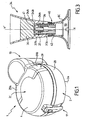
- the fryer 1 illustrated in Figures 1 to 3 is an electric fryer designed and sized for home use.
- the apparatus 1 according to the invention is therefore preferably a domestic appliance 1 cooking.
- the invention is however not limited to the family environment, and may also concern semi-professional or professional fryers.
- the domestic fryer 1 illustrated in the figures is preferably designed and dimensioned to fry particulate foods, such as pieces of potatoes, in order to obtain fries. These pieces of potatoes may have been cut manually by the user, or have been purchased already prepared commercially, fresh or frozen.
- the fryer 1 according to the invention is however not limited to the production of French fries, and can be used to fry other kinds of food (meat, fish, vegetables %) without as far as we go beyond the scope of the invention.
- the fryer according to the invention is preferably a deep-fat fryer.
- dry cooking is meant here a method of cooking food without immersion of the latter in a bath of oil or fat, that this immersion is partial and / or temporary during the cooking cycle.
- dry cooking refers to a cooking in which the food is certainly " wet " by a cooking medium (oil for example), but without being immersed or bathed in said medium. In this, the operating principle of such a fryer differs from that of a conventional fryer oil bath.
- the fryer 1 comprises, in a conventional manner, a main body 2 in which is mounted a receiving means 5 designed to receive within it food to cook.
- the main body 2 comprises a base 2A, intended to form the base of the fryer 1, and shaped to rest stably on a plane or a support.
- a side skirt 2B made for example of a metallic material or a plastic material, and forming the outer casing of the fryer 1.
- the side skirt 2B can present all appropriate geometric shapes and aesthetics.
- the skirt 2B has, in plan view, a generally “ 8 " shape, the top of the " 8 " defining the rear 10 of the fryer 1, while the base of the " 8 " defines the front 11 of said deep fryer 1.
- the main body 2 is provided with a lid 2C mounted movably between on the one hand a closed position (represented in FIG. figure 1 ), in which the cover 2C forms with the main body 2 a substantially closed enclosure, and on the other hand an open position (not shown), allowing the introduction of food to be cooked (in this case: to be fried) 2.
- the cover 2C forms, in cooperation with the skirt 2B and the base 2A, a closed housing, that is to say preferably substantially hermetic, allowing cooking in closed atmosphere.
- the substantially sealed closure of the main body 2 by the cover 2C can be achieved for example by means of seals (not shown in the figures).
- the cover 2C may be provided with a transparent zone 4 for monitoring the evolution of the frying inside the apparatus during the cooking cycle, when the lid 2C is closed on the main body 2.
- the fryer 1 also comprises a main heating means 24 designed to cook the food present in the receiving means 5 within the main body 2.
- main heating means means a heating means which alone ensures at least the bulk of the thermal input for cooking.
- the main heating means 24 is designed and arranged to ensure all of said heat input.
- the main heating means 24 may be of any type known to those skilled in the art, and in particular be designed to generate a heated flow oriented to strike substantially directly at least a portion of the food present in the receiving means 5, and that will be described in detail later.
- the main heating means 24 is integrated in the fryer 1, that is to say, it is mounted within the main body 2. It is however quite possible, without departing from the scope of the invention, the main heating means is external, that is to say independent of the fryer 1 and outside the latter.
- the fryer 1 comprises, mounted integral with the main body 2, a fat storage means 34.
- fat 35 which is substantially in liquid form when it is stored within the storage means 34. It is however quite possible that the fat 35 is in the form of a more or less soft solid.
- the storage means 34 will thus preferably be adapted to the physicochemical nature of the fat which it is intended to contain, and may therefore be provided with means for modifying the viscosity of the fat 35, constituted, for example , secondary heating means for fluidizing the fat 35. Said secondary heating means may be separate from the main heating means 24 or be constituted by the latter. In the latter case, a part of the thermal energy produced by the heating means 24 will therefore be used to fluidify, if necessary, the fat 35 contained in the storage means 34.
- the fat storage means 35 is distinct from the receiving means 5.
- the storage means 34 can contain fat 35 within the main body 2, but separately and isolated from the zone where the cooking takes place, namely the receiving means 5.
- the receiving means 5 and the storage means 34 therefore preferably define separate and separate reception volumes. The invention therefore allows the reception of fat, within the apparatus 1, outside the actual cooking zone.
- the storage means 34 is operatively connected to the receiving means 5 to feed said fat receiving means 35.
- the fat to be in contact with the food to be cooked in particular to promote the occurrence of the Maillard reaction, follows a path, preferably one-way, in two steps.
- This fat 35 is thus first stored in the storage means 34, then, automatically or at least on the user's control, is transferred into the receiving means 5, with the food to be cooked, so that they will be cooked in the presence of fat.
- the fat storage means 35 is operably connected to the receiving means 5 for transferring a predetermined amount of fat to the receiving means 5 for coating the fat foods for dry cooking purposes.
- the storage means 34 is designed to introduce, within the receiving means 5, a fat dose 35 whose quantity corresponds substantially to that required for the coating of food.
- the fat storage means 35 is thus preferably designed to transfer a quantity of fat substantially sufficient to cover the food with a fat film.
- This predetermined amount obviously depends on the nature of the amount of food, as well as the nature of the fat used, and in particular its viscosity.
- the storage means 34 is operatively connected to the receiving means 5 to feed said fat receiving means 35 by moving the fat 35 of the storage means 34 to and into the receiving means. 5.
- the functional link between the storage means 34 and the reception means 5 is one-way from the storage means to the reception means.
- the fat is not recycled from the receiving means 5 to the storage means 34.
- the storage means 34 thus makes it possible, at a given moment, to position within the receiving means 5 a predetermined quantity of fat, an amount corresponding preferably to that necessary and sufficient for a dry cooking, and this without direct manual intervention of the user, who himself does not have to directly feed the receiving means 5 fat.
- the receiving means 5 is designed and arranged to contain both the food and substantially all of the fat 35 likely to come from the storage means 34.
- the receiving means 5 comprises a container 8 comprising a bottom of the container 8A, from which side walls of the container 8B, 8C rise, so as to substantially delimit an internal volume 9 intended to accommodate the food to be cooked and cooking fat.
- said bottoms 8A and side walls 8B, 8C are substantially solid, that is to say not perforated, at least in the interface zone with the food and the fat, in order to avoid any leakage. the latter out of the container 8.
- the container bottom 8A is substantially flat and smooth, and has a generally flat crown shape, from the inner and outer periphery of which are raised in facing relation respectively an outer side wall 8B and an inner side wall 8C, such that the container 8 has substantially an annular channel shape, symmetry of revolution of vertical axis X-X '.
- the container 8 thus has a generally toroidal shape generated by the rotation about the axis of symmetry XX 'of an open profile substantially shaped " U ".
- the storage means 34 comprises a tank 34A provided with a discharge port 36, which orifice itself is provided with a closure means 37.
- the storage means 34 may be on the one hand in a recall and closure configuration (shown in figures 2 and 3 ), wherein the fat 35 is held by the sealing means 37 within the tank 34A, and on the other hand in an opening configuration, wherein the sealing means 37 permits the transfer of the fat 35 through the discharge port 36 out of the tank 34A to the receiving means 5, formed in this case by the container 8.
- the supply of the receiving means 5 is here fat in the fluid state, said fat flowing under the effect of gravity by the discharge port 36 when the latter is released from closing action of the sealing means 37.
- the closure means 37 is fixedly mounted in position relative to the main body 2 while the reservoir 34A is mounted movably relative to the closure means 37, between a first position, said high position, corresponding to the return configuration and closing of the storage means 34, and a second position, called the low position, corresponding to the opening configuration of the storage means 34.
- the tank 34A comprises a cup 34B provided at its base with a mouth 36A, formed for example by a cylindrical through recess formed in the lower part of the cup, and extending in the axial direction XX 'between one end 40 and an upper end 41. Said mouth 36A thus forms the discharge orifice 36.
- the sealing means 37 it preferably comprises a needle 37A, in the form of a rod arranged to be slidably inserted in the mouth 36A, said rod being provided at one of its ends with a diverging head 37B, generally frustoconical, intended to cooperate with the upper end 41 of the mouth 36A.
- the needle 37A diverging head 37B is mounted integral with the receiving means 5, formed in this case by the container 8. More particularly, the needle 37A has at its base a flared shape, which once reported on the container bottom 8A forms by itself the inner side wall 8C of the container 8.
- the respective dimensions, in cross section, of the needle 37A and the mouth 36A will be selected to allow a clearance between these parts, so as to create an annular orifice in the form of a ring, defined by the needle 37A and the mouth 36A.
- This crown-shaped opening around the needle promotes multidirectional flow of the fat 35 on or at the inner side wall 8C of the container 8.
- the cover 2C is functionally connected to the storage means 34 so that the closing position of the cover 2C corresponds substantially to the opening configuration of the storage means 34.
- the lid 2C is arranged to exert, when in the closed position, a downward thrust in the direction XX 'on the tank 34A, so as to move the latter from its upper position to its lower position causing and a relative movement of the needle 37A and the cup 34B, generating the flow of the fat 35.
- the supply of the container 8 is automatically within a closed enclosure, thus protecting the external environment and therefore the user of any particular projections.
- the storage means 34 comprises a fat metering means 35.
- This metering means can be constituted by the same volume capacity of the storage means 34, which can be predetermined and strictly correspond to a certain quantity and / or nature. food.
- This dosage means may also consist of a sensory registration system, comprising, for example, tactile graduations or visuals disposed on the body of the storage means 34, and allowing the user to know the volume of fat 35 contained in the storage means 34, and to control the volume of fat transferred to the receiving means 5.
- a sensory registration system comprising, for example, tactile graduations or visuals disposed on the body of the storage means 34, and allowing the user to know the volume of fat 35 contained in the storage means 34, and to control the volume of fat transferred to the receiving means 5.
- the dosing means allows the user to precisely control the amount of oil introduced into the cooking zone of the fryer, which allows a saving in fat while promoting a healthier kitchen.
- the storage means 34 is mounted on the receiving means, which can be removably mounted relative to the main body 2.
- the storage means 34 is itself removably mounted relative to the main body 2.
- the removable character of the storage means 34 can come from the removable nature of the receiving means 5. In fact, the extraction of the receiving means 5 out of the main body 2 will simultaneously extract the storage means 34, since the latter is mounted on the receiving means 5.
- the storage means 34 form an independent unit that is removably mounted relative to the rest of the apparatus and in particular relative to the container 8 or to any other element, such as the main body 2.
- This technical measure allows a particularly practical use of the fryer for the user, who can easily handle the storage means 34 for its filling with oil for example.
- This technical measure also allows interchangeability of the storage means. It is thus conceivable that the user has different storage means 34, distinguished for example by their volumetric capacities. The user can thus choose, according to the quantity and / or the quality of the food he wants to cook, a suitable storage means 34.
- the storage means 34 is designed for a single use exclusively, and may optionally have a disposable character.
- the user can obtain a storage medium in the trade and then connect it to his device.
- the user can thus benefit from particular oils or oil mixtures, possibly flavored and / or particularly adapted to a particular food.
- the fryer 1 comprises a stirring means 6 for the food contained in the receiving means 5.
- the fryer 1 comprises, mounted within the main body 2, a means for automatically coating the food to be fried with a film of fat.
- the invention is based on the principle of frying made by simply covering the surface of the foodstuffs. a thin layer of oil or other suitable fat.
- the cooking is not done in an oil bath, which involves the presence of a large amount of fat surrounding the food, but thanks to a small amount of oil forming a thin coating substantially homogeneous to the surface of each of the foods placed in the receiving means 5.
- the fat coating is performed automatically, that is to say without the need for an essential and direct contribution of the user for the establishment of the film of fat to the surface of the food.
- the user has only to be content to introduce the food in the deep fryer 1, within the main body 2, then activate the implementation of the automatic coating means (to the extent that this activation is not itself automatic) for the fryer 1 is loaded itself directly, within the main body 2, to individually coat the food with a thin layer of fat, without the user being forced to perform this operation itself manually.
- the means for automatically coating the food with a film of fat comprises on the one hand the receiving means 5, and on the other hand the riddling means 6.
- the receiving means 5 and the riddling means 6 are designed to be moved relative to each other, so as to stir and stir the food and the fat, so as to substantially cover each food item. a substantially uniform, homogeneous and continuous film of fat.
- the riddling means 6 is stationary mounted in position relative to the main body 2, while the receiving means 5 is first rotatably mounted relative to the main body 2 and riddling means 6, and secondly operably connected to a motor means 7 to be rotated by the latter.
- the fryer 1 may use stirring means mounted movably relative to the main body and to the receiving means, the receiving means being movably mounted. or immobile in position within the main body.
- the apparatus 1 according to the invention may comprise a riddling means 6 which is on the one hand rotatably mounted relative to the receiving means 5, and on the other hand operably connected to a motor means 7 to be rotated by the latter.
- the rotational drive of the container 8 of the fryer 1 illustrated in the figures is carried out using a first electric motor 7A 7 motor means, said first electric motor 7A being provided with an output shaft 7B extending substantially coaxially with the axis X-X ', and secured to the inner side wall 8C. More specifically, the output shaft 7B is embedded, preferably removably, in the sleeve 50 formed by the inner side wall 8C.
- the stirring means 6 comprises a blade 16 disposed within the internal volume 9 delimited by the container 8, so as to form a substantially immobile obstacle against the food set in motion by the rotation of the container 8.
- the container 8 is rotated using the first electric motor 7A, resulting in a generally circular movement of food and the fat around the axis X-X ', until the food meets the obstacle formed in this case by the blade 16, obstacle which helps to return and stir food and fat, thereby achieving rapid and substantially uniform coating of said foods.
- the blade 16 is also removably mounted on the main body 2.
- the blade 16 is integral (removably or not) with a handle 17, so that the blade 16 and the handle 17 form a sub-section. unitary and independent assembly that can be removably mounted on the main body 2.
- the fryer 1 comprises, mounted on the main body 2, a main heating means 24 designed to generate a heating flux 25, which is oriented to strike substantially directly at least a portion of the food within the main body 2.
- heating flux is meant here a directional thermal beam having a positive controlled dynamic character, on the contrary for example a simple natural convection effect that can be obtained by a purely static heating.
- heating flow 25 is directed to come to practice directly, without intermediate medium, on the food present in the container 8, this contributes to an excellent heat exchange, and provides, in cooperation with the film of oil present on food, cooking substantially equivalent to that obtained in oil bath but without the disadvantages of the latter.
- the heating flow 25 is a flow of hot air.
- the invention is however not limited to a flow of hot air, and one could envisage that the heating flow is from a heating infrared for example.
- Heating with hot air is however preferred, at least in the specific embodiment shown in the figures, because it gives better results than infra-red heating, especially in the case of manually cut food and having pieces of various size and thickness.
- the heating air flow 25 is directed substantially towards the blade 16.
- the blade 16 will contribute to maintaining agglutinated in its vicinity most or all of the foods present in the 8.
- it is sufficient to direct the flow of heated air 25 to the blade 16 to optimally heat the food, without the need to exert uniform heating over the entire container 8.
- the combination of a blade 16 and a localized hot air flow is therefore particularly advantageous in terms of cooking efficiency, energy saving and simplicity of design.
- the flow of hot air 25 is a recycled stream, that is to say that the fryer 1 works in a substantially closed atmosphere, air present inside the main body 2 being taken to be heated, then propelled on food. This hot, propelled air cools on contact with food, then is taken again to be warmed, and so on.
- the main heating means 24 comprises a centrifugal fan 26 generating a ventilation flow by sucking air into the main body 2 through at least one inlet opening 27, preferably arranged laterally relative to the container 8, and by discharging this air through at least one outlet port 28 in a pipe device 29, which opens towards and above the food present in the main body 2.
- the main heating means 24 comprises a heating element 30, for example of resistive nature positioned within the aeraulic flow, preferably downstream of the outlet port 28 in the direction of the flow, so as to transform the air flow in heating flux 25.
- the pipe device 29 comprises two ducts 29A, 29B extending Y-shaped at the periphery of the fryer 1 and originating, in common, substantially at the level of the heating element 30 or downstream of the latter, in the direction of flow.
- the ducts 29A, 29B are mounted in the cover 2C and each end, in the flow direction 25, by a nozzle 32 oriented obliquely relative to the axis X-X ', towards the front 11 and the bottom of the fryer 1.
- the heating air flow 25 thus comprises two distinct veins that converge, substantially symmetrically, to the blade 16. These two oppositely converging veins contribute to an excellent heat exchange with food, because they generate, at their meeting point, turbulence favoring the transmission of heat. It is understood, however, that the invention is not limited to a particular number of fluid streams, and that it is quite conceivable that the heating air stream comprises a single vein or more than two veins.
- the inner face of the container 8 intended to be facing the food, a coating based on a material consisting of mostly silicone.
- a silicone coating it is advantageous to cover the bottom 8A of the container 8 with a silicone coating, because the silicone, thanks to its microporous properties, has specific qualities of reaction with the fat (emulsion) which make it possible to obtain a better distribution of the oil on the food all maintaining an excellent coefficient of friction, which is useful for preserving the integrity of food during brewing coating.
- such a silicone dish has the ability to heat the fries that are in contact with it, without burning or overcooling as would a metal dish for example.
- the Applicant has thus found that the conductive transfer properties between French fries and a silicone dish are substantially comparable to the forced convection transfer properties of the hot air on French fries. Thanks to such a coating of silicone, the uniformity of cooking is ensured by avoiding in particular any browning of the chips fries.
- PTFE polytetrafluoroethylene
- the fryer 1 forms, in operation (that is to say when the lid 2C is closed), a substantially closed cooking chamber, that is to say preferably sealed said enclosure preferably being provided with calibrated steam leakage means to the outside (not shown).
- the calibrated vapor leakage means comprises a leakage orifice (not shown), preferably disposed in the vicinity of the inlet port 27 of the fan 26, which allows a continuous controlled evacuation of the steam while throughout the cooking cycle, as well as a controlled renewal of the air inside the enclosure.
- the apparatus according to the invention may comprise an orifice for filling the storage means 34 when the cover 2C closes the main body 2.
- This auxiliary orifice which may be extended by a conduit, is for example arranged in the lid 2C, or more generally in the main body 2.
- the user introduces said pieces of potatoes into the plate 8.
- the user also introduces a small amount of oil (for example 30 grams or less) in the cup 34B.
- the user can perform this filling separately, without manipulating the entire device.
- the storage means 34 is removable and disposable
- the user will only have to connect the storage means 34, bought at the for example, on the fryer.
- the fryer has docking means that allow it to receive the storage means 34 and establish fluid communication between the contents of the storage means 34 and the receiving means 5.
- the storage means 34 is moreover preferably sized to be able to contain at most a quantity of fat substantially necessary and sufficient to coat the food contained by the receiving means 5.
- This emptying is ideally performed in all directions, along or at the inner side wall 8C, which helps to promote rapid coating of food.
- the storage means 34 thus allows, prior to the actual cooking, a spill of new oil " cold ", that is to say unheated, or at least not at a temperature sufficient to assimilate this oil to a means heating.
- This oil is preferably discharged at atmospheric pressure, without pressurization or vaporization to avoid including splashing within the device.
- the cooking cycle then starts, which causes the rotation of the container 8 around the axis XX 'and thus the stirring with the fixed blade 16 pieces of potatoes and oil spread in the dish .
- This brewing leads to the establishment of a film of oil on the surface of each piece of potato.
- the fan 26 and the heating element 30 are started, which leads to the establishment of a flow of hot air 25 which directly heats the pieces of potatoes. coated with oil.
- the container 8 therefore also serves as a cooking vessel.
- a first phase of the cooking cycle the pulsed air heats the potato pieces of the upper layer, which quickly produce water vapor.
- This cooking mechanism in a saturated steam environment thus allows a rapid and homogeneous heating of all pieces of potatoes present in the container 8. This homogeneous heating is facilitated by the permanent mixing of the pieces operated by the rotary container 8 and the blade 16.
- an equilibrium is created between evaporation and recondensation, until the water vapor has been progressively evacuated out of the fryer by the calibrated leakage means.
- the cooking cycle being completed the user can then open the lid 2C and simultaneously extract the container 8 and the blade 16 with the aid of the removable handle 17.
- the container 8, on which is mounted the storage means 34 then serves as a serving dish, and now contains ready-to-serve fries whose taste and appearance are similar to the fresh fries cooked in a oil bath.
- the invention finds its industrial application in the design, manufacture and use of a food cooking appliance.
Landscapes
- Engineering & Computer Science (AREA)
- Food Science & Technology (AREA)
- Frying-Pans Or Fryers (AREA)
- Vending Machines For Individual Products (AREA)
- Food-Manufacturing Devices (AREA)
- Cookers (AREA)
Claims (22)
- - Haushaltsvorrichtung (1) zum Garen von Nahrungsmitteln in Anwesenheit von Fett, umfassend einerseits einen Hauptkörper (2), in dessen Inneren ein Aufnahmemittel (5) montiert ist, das dazu eingerichtet ist, in seinem Inneren die Nahrungsmittel zum Garen aufzunehmen und andererseits ein Hauptheizmittel (24), das dazu eingerichtet ist, die Nahrungsmittel zu garen, dadurch gekennzeichnet, dass sie, fest mit dem Hauptköper (2) verbunden, ein Aufbewahrungsmittel (34) des Fettes (35) umfasst, das vom Aufnahmemittel (5) verschieden ist und funktionell mit letzterem verbunden ist, um in das Aufnahmemittel (5) eine vorbestimmte Menge von Fett übertragen zu können, um die Lebensmittel mit Fett zu beschichten, um eine trockene Garung der Lebensmittel durchzuführen, wobei das Aufnahmemittel (5) dazu eingerichtet und angeordnet ist, um gleichzeitig die Nahrungsmittel und im Wesentlichen das gesamte Fett (35), das aus dem Aufbewahrungsmittel (34) stammen kann, zu enthalten.
- - Vorrichtung (1) nach Anspruch 1, dadurch gekennzeichnet, dass das Aufnahmemittel (5) einen Behälter (8) umfasst, der einen Behälterboden aufweist, von dem aus sich seitliche Behälterwände (8B und 8C) erheben, um ein inneres Volumen (9) abzugrenzen, das dazu dient, die Nahrungsmittel zum Garen und das Fett (35) aufzunehmen, wobei der Boden (8A) und die seitlichen Wände (8B, 8C) im Wesentlichen eben sind.
- - Vorrichtung (1) nach einem der Ansprüche 1 und 2, dadurch gekennzeichnet, dass sie ein Mittel zum Umrühren (6) der Nahrungsmittel umfasst, die im Aufnahmemittel (5) enthalten sind.
- - Vorrichtung (1) nach Anspruch 3, dadurch gekennzeichnet, dass das Aufnahmemittel (5) und das Mittel zum Umrühren (6) dazu eingerichtet sind, in Bezug zueinander in Bewegung gesetzt zu werden, um die Nahrungsmittel umzurühren.
- - Vorrichtung (1) nach Anspruch 4, dadurch gekennzeichnet, dass das Mittel zum Umrühren (6) einerseits beweglich zur Drehung bezüglich des Aufnahmemittels (5) montiert ist, und andererseits funktionell mit einem Motormittel (7) verbunden isL, um durch letzteres in Rotation versetzt zu werden.
- - Vorrichtung (1) nach einem der Ansprüche 1 bis 5, dadurch gekennzeichnet, dass das Hauptheizmittel (24) dazu eingerichtet ist, einen Heizstrom (25) zu erzeugen, der ausgerichtet ist, um mindestens auf einen Teil der Nahrungsmittel im Wesentlichen direkt zu treffen.
- - Vorrichtung (7) nach Anspruch 6, dadurch gekennzeichnet, dass der Heizstrom (25) ein Heißluftstrom ist.
- - Vorrichtung (1) nach einem der Ansprüche 1 bis 7, dadurch gekennzeichnet, dass das Hauptheizmittel (24) im Inneren des Hauptkörpers (2) montiert ist.
- - Vorrichtung (1) nach einem der Ansprüche 1 bis 8, dadurch gekennzeichnet, dass sie in Betrieb einen im Wesentlichen geschlossenen Garraum bildet, der mit einem Mittel zum geregelten Austritt von Dampf in den Außenraum ausgestattet ist.
- - Vorrichtung (1) nach einem der Ansprüche 1 bis 9, dadurch gekennzeichnet, dass das Aufbewahrungsmittel (34) einen Behälter (34A) umfasst, der mit einer Ausgießöffnung (36) versehen ist, die ihrerseits mit einem Verschlussmittel (37) versehen ist, wobei das Aufbewahrungsmittel (34) dazu geeignet ist, sich einerseits in einer Konfiguration der Rückstellung und des Verschlusses zu befinden, in der das Fett (35) durch das Verschlussmittel (37) im Inneren des Behälters (34A) gehalten wird, und andererseits in einer Konfiguration der Öffnung, in der das Verschlussmittel (37) die Übertragung des Fettes (35) durch die Ausgießöffnung (36) aus dem Behälter (34A) in das Aufnahmemittel (5) zulässt.
- - Vorrichtung (1) nach Anspruch 10, dadurch gekennzeichnet, dass das Verschlussmittel (37) fest in einer Position bezüglich des Hauptkörpers (2) montiert ist, während der Behälter (34A) beweglich bezüglich des Verschlussmittels (37) montiert ist.
- - Vorrichtung (1) nach Anspruch 11, dadurch gekennzeichnet, dass der Behälter (34A) einen Becher (34B) umfasst, der an seinem Fuβ mit einer Mündung ausgestattet ist, die eine Ausgießöffnung (36) bildet, wobei das Verschlussmittel (37) ein Nadelventil (37A) mit einem sich erweiternden Kopf (37B) umfasst, der mit dem Aufnahmemittel (b) fest verbunden und in die Mündung (36A) eingeführt ist, wobei der Becher (34B) elastisch gleitbar bezüglich des Nadelventils (37A) zwischen einerseits einer oberen Position, die der Konfiguration der Rückstellung und des Verschlusses entspricht, in der der sich erweiternde Kopf (37B) mit der Mündung (36A) in Kontakt ist, um die Mündung (36A) zu schließen, und andererseits einer unteren Position montiert ist, in der der sich erweiternde Kopf (37B) von der Mündung (36A) entfernt ist und so den Durchgang des Fettes (35) durch die Mündung (36A) aus dem Becher (34B) zulässt.
- - Vorrichtung (1) nach einem der Ansprüche 10 bis 12, dadurch gekennzeichnet, dass der Hauptkörper (2) mit einem Deckel (2C) versehen ist, der beweglich zwischen einerseits einer Position des Verschlusses, in der der Deckel (2C) mit dem Hauptkörper (2) einen Raum bildet, der im Wesentlichen geschlossen ist, und andererseits einer Position der Öffnung montiert isL, die die Einführung der zu bratenden Nahrungsmittel in das Aufnahmemittel (5) zulässt, wobei der Deckel (2C) funktionell miL dem Aufbewahrungsmittel (34) verbunden ist, damit die Position des Verschlusses des Deckels (2C) im Wesentlichen der Konfiguration der Öffnung des Aufbewahrungsmittel (34) entspricht.
- - Vorrichtung (1) nach den Ansprüchen 12 und 13, dadurch gekennzeichnet, dass der Deckel (2C) so angeordnet ist, dass er, wenn er sich in der Position des Verschlusses befindet, auf den Behälter (34A) einen Druck ausübt, um letzteren von seiner oberen Position in seine untere Position zu bringen.
- - Vorrichtung (1) nach einem der Ansprüche 1 bis 14, dadurch gekennzeichnet, dass das Aufbewahrungsmittel (34) ein Mittel zur Dosierung des Fettes umfasst.
- - Vorrichtung (1) nach einem der Ansprüche 1 bis 15, dadurch gekennzeichnet, dass das Aufbewahrungsmittel (34) auf dem Aufnahmemittel (5) montiert ist.
- - Vorrichtung (1) nach einem der Ansprüche 1 bis 16, dadurch gekennzeichnet, dass das Aufbewahrungsmittel (34) bezüglich des Hauptkörpers (2) abnehmbar montiert ist.
- - Vorrichtung (1) nach einem der Ansprüche 1 bis 17, dadurch gekennzeichnet, dass das Aufbewahrungsmittel (34) ausschließlich für eine einzige Verwendung eingerichtet ist.
- - Vorrichtung (1) nach einem der Ansprüche 1 bis 18, dadurch gekennzeichnet, dass das Aufbewahrungsmittel (34) so dimensioniert ist, dass es höchstens eine Menge Fett (35) enthalten kann, die im Wesentlichen notwendig und ausreichend ist, um die Nahrungsmittel, die im Aufnahmemittel (5) enthalten sind, mit Fett zu beschichten.
- - Vorrichtung (1) nach einem der Ansprüche 1 bis 19, dadurch gekennzeichnet, dass sie so eingerichtet und dimensioniert ist, um bestimmte Nahrungsmittel wie z.B. Kartoffelstücke zu garen.
- - Vorrichtung (1) nach einem der Ansprüche 1 bis 2.0, dadurch gekennzeichnet, dass sie aus einer Friteuse besteht.
- - Aufbewahrungsmittel (34) für Fett (35) für die Garvorrichtung (1) nach einem der Ansprüche 1 bis 21.
Applications Claiming Priority (2)
| Application Number | Priority Date | Filing Date | Title |
|---|---|---|---|
| FR0406220A FR2871043B1 (fr) | 2004-06-08 | 2004-06-08 | Appareil de cuisson avec moyen de stockage de matiere grasse, et moyen de stockage de matiere grasse pour un tel appareil |
| PCT/FR2005/001417 WO2006000701A1 (fr) | 2004-06-08 | 2005-06-08 | Appareil de cuisson avec moyen de stockage de matiere grasse et moyen de stockage de matiere grasse pour un tel appareil |
Publications (2)
| Publication Number | Publication Date |
|---|---|
| EP1781155A1 EP1781155A1 (de) | 2007-05-09 |
| EP1781155B1 true EP1781155B1 (de) | 2008-03-05 |
Family
ID=34946183
Family Applications (1)
| Application Number | Title | Priority Date | Filing Date |
|---|---|---|---|
| EP05775239A Active EP1781155B1 (de) | 2004-06-08 | 2005-06-08 | Garvorrichtung mit einem mittel zur fettaufbewahrung und fettaufbewahrungsmittel für die vorrichtung |
Country Status (6)
| Country | Link |
|---|---|
| EP (1) | EP1781155B1 (de) |
| AT (1) | ATE387878T1 (de) |
| DE (1) | DE602005005203T2 (de) |
| ES (1) | ES2304019T3 (de) |
| FR (1) | FR2871043B1 (de) |
| WO (1) | WO2006000701A1 (de) |
Families Citing this family (3)
| Publication number | Priority date | Publication date | Assignee | Title |
|---|---|---|---|---|
| FR2905255B1 (fr) | 2006-09-01 | 2014-12-26 | Seb Sa | Appareil de cuisson |
| FR3004630B1 (fr) | 2013-04-19 | 2015-07-17 | Seb Sa | Procede de cuisson pour appareil de cuisson avec moyen de remuage et appareil de cuisson correspondant |
| BE1025368B1 (fr) | 2017-07-04 | 2019-02-08 | Philippe Donfut | Appareil pour la préparation d'aliments cuits en parties découpées et en présence de matière grasse |
Family Cites Families (5)
| Publication number | Priority date | Publication date | Assignee | Title |
|---|---|---|---|---|
| US2078641A (en) * | 1936-02-27 | 1937-04-27 | James W Dunlap | Doughnut cooking machine |
| US4050447A (en) * | 1976-05-24 | 1977-09-27 | Andrew Terracciano | Deep fat fryer heated fat supply reservoir and fat replenishment device |
| JPH05146363A (ja) * | 1991-11-29 | 1993-06-15 | Star Shokuhin Kogyo Kk | 乾燥天ぷら製造装置におけるコロモ液定量自動供給装置 |
| CH691425A5 (de) * | 1994-12-21 | 2001-07-31 | Rahel Mutzner | Fritiervorrichtung mit Temperaturregelung. |
| MXPA02011544A (es) * | 2000-05-24 | 2005-09-08 | Terra Chips B V | Metodo y aparato para la fritura de productos. |
-
2004
- 2004-06-08 FR FR0406220A patent/FR2871043B1/fr not_active Expired - Fee Related
-
2005
- 2005-06-08 ES ES05775239T patent/ES2304019T3/es active Active
- 2005-06-08 EP EP05775239A patent/EP1781155B1/de active Active
- 2005-06-08 AT AT05775239T patent/ATE387878T1/de not_active IP Right Cessation
- 2005-06-08 DE DE602005005203T patent/DE602005005203T2/de active Active
- 2005-06-08 WO PCT/FR2005/001417 patent/WO2006000701A1/fr active IP Right Grant
Also Published As
| Publication number | Publication date |
|---|---|
| WO2006000701A1 (fr) | 2006-01-05 |
| DE602005005203D1 (de) | 2008-04-17 |
| ES2304019T3 (es) | 2008-09-01 |
| ATE387878T1 (de) | 2008-03-15 |
| FR2871043B1 (fr) | 2006-12-22 |
| FR2871043A1 (fr) | 2005-12-09 |
| EP1781155A1 (de) | 2007-05-09 |
| DE602005005203T2 (de) | 2009-03-19 |
Similar Documents
| Publication | Publication Date | Title |
|---|---|---|
| EP1781154B1 (de) | Fritteuse mit automatischem fettüberzug | |
| EP1768535B1 (de) | Luftstromkochvorrichtung | |
| EP2052654B1 (de) | Kochgerät mit Mittel zum Umrühren und entsprechendes Verfahren | |
| EP2651271B1 (de) | Kochvorrichtung für nahrungsmittel mit einer rührklinge | |
| CA3047203C (fr) | Accessoire cuiseur vapeur modulaire pour chauffer et/ou cuire a la vapeur des aliments contenus dans un recipient | |
| EP1912875A2 (de) | Verpackungsschachtel zum verpacken, konservieren, dämpfen per mikrowelle und verzehr von nahrungsmitteln | |
| WO1996000027A1 (fr) | Appareil de cuisson electrique d'aliments precuits, surgeles ou frais de type friteuse sans bain d'huile | |
| EP1781155B1 (de) | Garvorrichtung mit einem mittel zur fettaufbewahrung und fettaufbewahrungsmittel für die vorrichtung | |
| EP2536316B1 (de) | Korb für ein elektrisches gerät zum dampfgaren von speisen oder für ein kochutensil | |
| EP3661396B1 (de) | Vorrichtung zur zubereitung von in gegenwart von fett gekochten zerkleinerten lebensmitteln | |
| EP3351149B1 (de) | Marmeladen-fontäne | |
| FR2559369A2 (fr) | Appareil culinaire pour preparer des sandwichs du genre dits " hamburgers " | |
| EP1739364A2 (de) | Ofen mit einem Wasser-Verdampfer | |
| FR2494975A1 (fr) | Cuiseur d'aliments a evacuation automatique de liquides a la fin de la cuisson | |
| EP2213212B1 (de) | Vorrichtung zum Aufwärmen von Lebensmitteln für Kleinkinder | |
| FR2888222A1 (fr) | Boite d'emballage pour le conditionnement, la conservation, la cuisson vapeur au four a micro-ondes et la consommation d'aliments | |
| FR2705549A1 (fr) | Appareil domestique ou pour collectivités de cuisson à la vapeur. | |
| FR2789285A1 (fr) | Element de cuisson specialise pour cuiseur a la vapeur |
Legal Events
| Date | Code | Title | Description |
|---|---|---|---|
| PUAI | Public reference made under article 153(3) epc to a published international application that has entered the european phase |
Free format text: ORIGINAL CODE: 0009012 |
|
| 17P | Request for examination filed |
Effective date: 20070108 |
|
| AK | Designated contracting states |
Kind code of ref document: A1 Designated state(s): AT BE BG CH CY CZ DE DK EE ES FI FR GB GR HU IE IS IT LI LT LU MC NL PL PT RO SE SI SK TR |
|
| GRAP | Despatch of communication of intention to grant a patent |
Free format text: ORIGINAL CODE: EPIDOSNIGR1 |
|
| DAX | Request for extension of the european patent (deleted) | ||
| GRAS | Grant fee paid |
Free format text: ORIGINAL CODE: EPIDOSNIGR3 |
|
| GRAA | (expected) grant |
Free format text: ORIGINAL CODE: 0009210 |
|
| AK | Designated contracting states |
Kind code of ref document: B1 Designated state(s): AT BE BG CH CY CZ DE DK EE ES FI FR GB GR HU IE IS IT LI LT LU MC NL PL PT RO SE SI SK TR |
|
| REG | Reference to a national code |
Ref country code: GB Ref legal event code: FG4D Free format text: NOT ENGLISH |
|
| REG | Reference to a national code |
Ref country code: CH Ref legal event code: EP |
|
| REG | Reference to a national code |
Ref country code: IE Ref legal event code: FG4D Free format text: LANGUAGE OF EP DOCUMENT: FRENCH |
|
| REF | Corresponds to: |
Ref document number: 602005005203 Country of ref document: DE Date of ref document: 20080417 Kind code of ref document: P |
|
| PG25 | Lapsed in a contracting state [announced via postgrant information from national office to epo] |
Ref country code: FI Free format text: LAPSE BECAUSE OF FAILURE TO SUBMIT A TRANSLATION OF THE DESCRIPTION OR TO PAY THE FEE WITHIN THE PRESCRIBED TIME-LIMIT Effective date: 20080305 |
|
| PGFP | Annual fee paid to national office [announced via postgrant information from national office to epo] |
Ref country code: ES Payment date: 20080603 Year of fee payment: 4 |
|
| PG25 | Lapsed in a contracting state [announced via postgrant information from national office to epo] |
Ref country code: AT Free format text: LAPSE BECAUSE OF FAILURE TO SUBMIT A TRANSLATION OF THE DESCRIPTION OR TO PAY THE FEE WITHIN THE PRESCRIBED TIME-LIMIT Effective date: 20080305 |
|
| REG | Reference to a national code |
Ref country code: ES Ref legal event code: FG2A Ref document number: 2304019 Country of ref document: ES Kind code of ref document: T3 |
|
| PG25 | Lapsed in a contracting state [announced via postgrant information from national office to epo] |
Ref country code: SI Free format text: LAPSE BECAUSE OF FAILURE TO SUBMIT A TRANSLATION OF THE DESCRIPTION OR TO PAY THE FEE WITHIN THE PRESCRIBED TIME-LIMIT Effective date: 20080305 Ref country code: PL Free format text: LAPSE BECAUSE OF FAILURE TO SUBMIT A TRANSLATION OF THE DESCRIPTION OR TO PAY THE FEE WITHIN THE PRESCRIBED TIME-LIMIT Effective date: 20080305 |
|
| REG | Reference to a national code |
Ref country code: IE Ref legal event code: FD4D |
|
| PG25 | Lapsed in a contracting state [announced via postgrant information from national office to epo] |
Ref country code: SE Free format text: LAPSE BECAUSE OF FAILURE TO SUBMIT A TRANSLATION OF THE DESCRIPTION OR TO PAY THE FEE WITHIN THE PRESCRIBED TIME-LIMIT Effective date: 20080605 Ref country code: SK Free format text: LAPSE BECAUSE OF FAILURE TO SUBMIT A TRANSLATION OF THE DESCRIPTION OR TO PAY THE FEE WITHIN THE PRESCRIBED TIME-LIMIT Effective date: 20080305 Ref country code: CZ Free format text: LAPSE BECAUSE OF FAILURE TO SUBMIT A TRANSLATION OF THE DESCRIPTION OR TO PAY THE FEE WITHIN THE PRESCRIBED TIME-LIMIT Effective date: 20080305 Ref country code: PT Free format text: LAPSE BECAUSE OF FAILURE TO SUBMIT A TRANSLATION OF THE DESCRIPTION OR TO PAY THE FEE WITHIN THE PRESCRIBED TIME-LIMIT Effective date: 20080805 |
|
| PGFP | Annual fee paid to national office [announced via postgrant information from national office to epo] |
Ref country code: NL Payment date: 20080618 Year of fee payment: 4 |
|
| PG25 | Lapsed in a contracting state [announced via postgrant information from national office to epo] |
Ref country code: RO Free format text: LAPSE BECAUSE OF FAILURE TO SUBMIT A TRANSLATION OF THE DESCRIPTION OR TO PAY THE FEE WITHIN THE PRESCRIBED TIME-LIMIT Effective date: 20080305 |
|
| BERE | Be: lapsed |
Owner name: SEB S.A. Effective date: 20080630 |
|
| PG25 | Lapsed in a contracting state [announced via postgrant information from national office to epo] |
Ref country code: IS Free format text: LAPSE BECAUSE OF FAILURE TO SUBMIT A TRANSLATION OF THE DESCRIPTION OR TO PAY THE FEE WITHIN THE PRESCRIBED TIME-LIMIT Effective date: 20080705 |
|
| PLBE | No opposition filed within time limit |
Free format text: ORIGINAL CODE: 0009261 |
|
| STAA | Information on the status of an ep patent application or granted ep patent |
Free format text: STATUS: NO OPPOSITION FILED WITHIN TIME LIMIT |
|
| PG25 | Lapsed in a contracting state [announced via postgrant information from national office to epo] |
Ref country code: IE Free format text: LAPSE BECAUSE OF FAILURE TO SUBMIT A TRANSLATION OF THE DESCRIPTION OR TO PAY THE FEE WITHIN THE PRESCRIBED TIME-LIMIT Effective date: 20080305 Ref country code: DK Free format text: LAPSE BECAUSE OF FAILURE TO SUBMIT A TRANSLATION OF THE DESCRIPTION OR TO PAY THE FEE WITHIN THE PRESCRIBED TIME-LIMIT Effective date: 20080305 Ref country code: LT Free format text: LAPSE BECAUSE OF FAILURE TO SUBMIT A TRANSLATION OF THE DESCRIPTION OR TO PAY THE FEE WITHIN THE PRESCRIBED TIME-LIMIT Effective date: 20080305 Ref country code: MC Free format text: LAPSE BECAUSE OF NON-PAYMENT OF DUE FEES Effective date: 20080630 |
|
| 26N | No opposition filed |
Effective date: 20081208 |
|
| PG25 | Lapsed in a contracting state [announced via postgrant information from national office to epo] |
Ref country code: BE Free format text: LAPSE BECAUSE OF NON-PAYMENT OF DUE FEES Effective date: 20080630 |
|
| PG25 | Lapsed in a contracting state [announced via postgrant information from national office to epo] |
Ref country code: EE Free format text: LAPSE BECAUSE OF FAILURE TO SUBMIT A TRANSLATION OF THE DESCRIPTION OR TO PAY THE FEE WITHIN THE PRESCRIBED TIME-LIMIT Effective date: 20080305 Ref country code: BG Free format text: LAPSE BECAUSE OF FAILURE TO SUBMIT A TRANSLATION OF THE DESCRIPTION OR TO PAY THE FEE WITHIN THE PRESCRIBED TIME-LIMIT Effective date: 20080605 |
|
| PG25 | Lapsed in a contracting state [announced via postgrant information from national office to epo] |
Ref country code: CY Free format text: LAPSE BECAUSE OF FAILURE TO SUBMIT A TRANSLATION OF THE DESCRIPTION OR TO PAY THE FEE WITHIN THE PRESCRIBED TIME-LIMIT Effective date: 20080305 |
|
| REG | Reference to a national code |
Ref country code: CH Ref legal event code: PL |
|
| NLV4 | Nl: lapsed or anulled due to non-payment of the annual fee |
Effective date: 20100101 |
|
| PG25 | Lapsed in a contracting state [announced via postgrant information from national office to epo] |
Ref country code: LI Free format text: LAPSE BECAUSE OF NON-PAYMENT OF DUE FEES Effective date: 20090630 Ref country code: CH Free format text: LAPSE BECAUSE OF NON-PAYMENT OF DUE FEES Effective date: 20090630 |
|
| PG25 | Lapsed in a contracting state [announced via postgrant information from national office to epo] |
Ref country code: DE Free format text: LAPSE BECAUSE OF NON-PAYMENT OF DUE FEES Effective date: 20100101 |
|
| PG25 | Lapsed in a contracting state [announced via postgrant information from national office to epo] |
Ref country code: NL Free format text: LAPSE BECAUSE OF NON-PAYMENT OF DUE FEES Effective date: 20100101 Ref country code: HU Free format text: LAPSE BECAUSE OF FAILURE TO SUBMIT A TRANSLATION OF THE DESCRIPTION OR TO PAY THE FEE WITHIN THE PRESCRIBED TIME-LIMIT Effective date: 20080906 Ref country code: LU Free format text: LAPSE BECAUSE OF NON-PAYMENT OF DUE FEES Effective date: 20080608 |
|
| REG | Reference to a national code |
Ref country code: ES Ref legal event code: FD2A Effective date: 20090609 |
|
| PG25 | Lapsed in a contracting state [announced via postgrant information from national office to epo] |
Ref country code: TR Free format text: LAPSE BECAUSE OF FAILURE TO SUBMIT A TRANSLATION OF THE DESCRIPTION OR TO PAY THE FEE WITHIN THE PRESCRIBED TIME-LIMIT Effective date: 20080305 |
|
| PG25 | Lapsed in a contracting state [announced via postgrant information from national office to epo] |
Ref country code: ES Free format text: LAPSE BECAUSE OF NON-PAYMENT OF DUE FEES Effective date: 20090609 Ref country code: GR Free format text: LAPSE BECAUSE OF FAILURE TO SUBMIT A TRANSLATION OF THE DESCRIPTION OR TO PAY THE FEE WITHIN THE PRESCRIBED TIME-LIMIT Effective date: 20080606 |
|
| PGFP | Annual fee paid to national office [announced via postgrant information from national office to epo] |
Ref country code: IT Payment date: 20080630 Year of fee payment: 4 |
|
| REG | Reference to a national code |
Ref country code: FR Ref legal event code: PLFP Year of fee payment: 12 |
|
| REG | Reference to a national code |
Ref country code: FR Ref legal event code: CA Effective date: 20170518 |
|
| REG | Reference to a national code |
Ref country code: FR Ref legal event code: PLFP Year of fee payment: 13 |
|
| REG | Reference to a national code |
Ref country code: FR Ref legal event code: PLFP Year of fee payment: 14 |
|
| PGFP | Annual fee paid to national office [announced via postgrant information from national office to epo] |
Ref country code: DE Payment date: 20180607 Year of fee payment: 14 |
|
| REG | Reference to a national code |
Ref country code: DE Ref legal event code: R119 Ref document number: 602005005203 Country of ref document: DE |
|
| PG25 | Lapsed in a contracting state [announced via postgrant information from national office to epo] |
Ref country code: DE Free format text: LAPSE BECAUSE OF NON-PAYMENT OF DUE FEES Effective date: 20200101 |
|
| PGFP | Annual fee paid to national office [announced via postgrant information from national office to epo] |
Ref country code: FR Payment date: 20210630 Year of fee payment: 17 |
|
| PGFP | Annual fee paid to national office [announced via postgrant information from national office to epo] |
Ref country code: GB Payment date: 20210622 Year of fee payment: 17 |
|
| GBPC | Gb: european patent ceased through non-payment of renewal fee |
Effective date: 20220608 |
|
| PG25 | Lapsed in a contracting state [announced via postgrant information from national office to epo] |
Ref country code: FR Free format text: LAPSE BECAUSE OF NON-PAYMENT OF DUE FEES Effective date: 20220630 |
|
| PG25 | Lapsed in a contracting state [announced via postgrant information from national office to epo] |
Ref country code: GB Free format text: LAPSE BECAUSE OF NON-PAYMENT OF DUE FEES Effective date: 20220608 |