EP1780482A1 - Cooling system for superconducting power apparatus - Google Patents
Cooling system for superconducting power apparatus Download PDFInfo
- Publication number
- EP1780482A1 EP1780482A1 EP05751512A EP05751512A EP1780482A1 EP 1780482 A1 EP1780482 A1 EP 1780482A1 EP 05751512 A EP05751512 A EP 05751512A EP 05751512 A EP05751512 A EP 05751512A EP 1780482 A1 EP1780482 A1 EP 1780482A1
- Authority
- EP
- European Patent Office
- Prior art keywords
- gas
- reservoir tank
- liquefied gas
- pressurizing
- power apparatus
- Prior art date
- Legal status (The legal status is an assumption and is not a legal conclusion. Google has not performed a legal analysis and makes no representation as to the accuracy of the status listed.)
- Withdrawn
Links
- 238000001816 cooling Methods 0.000 title claims abstract description 59
- 239000007788 liquid Substances 0.000 claims abstract description 109
- 239000007789 gas Substances 0.000 claims description 192
- IJGRMHOSHXDMSA-UHFFFAOYSA-N Atomic nitrogen Chemical compound N#N IJGRMHOSHXDMSA-UHFFFAOYSA-N 0.000 claims description 169
- 229910001873 dinitrogen Inorganic materials 0.000 claims description 22
- 230000001105 regulatory effect Effects 0.000 claims description 9
- 238000010438 heat treatment Methods 0.000 claims description 3
- 238000005086 pumping Methods 0.000 claims description 3
- 238000001704 evaporation Methods 0.000 claims description 2
- 229910052757 nitrogen Inorganic materials 0.000 description 74
- 238000009835 boiling Methods 0.000 description 11
- 238000000034 method Methods 0.000 description 9
- 238000009413 insulation Methods 0.000 description 8
- 238000010586 diagram Methods 0.000 description 4
- 239000001307 helium Substances 0.000 description 4
- 229910052734 helium Inorganic materials 0.000 description 4
- SWQJXJOGLNCZEY-UHFFFAOYSA-N helium atom Chemical compound [He] SWQJXJOGLNCZEY-UHFFFAOYSA-N 0.000 description 4
- 230000003247 decreasing effect Effects 0.000 description 3
- 238000004090 dissolution Methods 0.000 description 3
- 238000002474 experimental method Methods 0.000 description 3
- XLYOFNOQVPJJNP-UHFFFAOYSA-N water Substances O XLYOFNOQVPJJNP-UHFFFAOYSA-N 0.000 description 3
- 239000011810 insulating material Substances 0.000 description 2
- 238000011160 research Methods 0.000 description 2
- RYGMFSIKBFXOCR-UHFFFAOYSA-N Copper Chemical compound [Cu] RYGMFSIKBFXOCR-UHFFFAOYSA-N 0.000 description 1
- JOYRKODLDBILNP-UHFFFAOYSA-N Ethyl urethane Chemical compound CCOC(N)=O JOYRKODLDBILNP-UHFFFAOYSA-N 0.000 description 1
- 230000005540 biological transmission Effects 0.000 description 1
- 230000015556 catabolic process Effects 0.000 description 1
- 229910052802 copper Inorganic materials 0.000 description 1
- 239000010949 copper Substances 0.000 description 1
- 230000002950 deficient Effects 0.000 description 1
- 230000006866 deterioration Effects 0.000 description 1
- 230000000694 effects Effects 0.000 description 1
- 238000000605 extraction Methods 0.000 description 1
- 230000002349 favourable effect Effects 0.000 description 1
- 238000005187 foaming Methods 0.000 description 1
- 239000001257 hydrogen Substances 0.000 description 1
- 229910052739 hydrogen Inorganic materials 0.000 description 1
- 125000004435 hydrogen atom Chemical class [H]* 0.000 description 1
- 238000009434 installation Methods 0.000 description 1
- 239000012212 insulator Substances 0.000 description 1
- QJGQUHMNIGDVPM-UHFFFAOYSA-N nitrogen group Chemical group [N] QJGQUHMNIGDVPM-UHFFFAOYSA-N 0.000 description 1
- 230000000630 rising effect Effects 0.000 description 1
- 238000010792 warming Methods 0.000 description 1
- 238000004804 winding Methods 0.000 description 1
Images

Classifications
-
- H—ELECTRICITY
- H01—ELECTRIC ELEMENTS
- H01B—CABLES; CONDUCTORS; INSULATORS; SELECTION OF MATERIALS FOR THEIR CONDUCTIVE, INSULATING OR DIELECTRIC PROPERTIES
- H01B12/00—Superconductive or hyperconductive conductors, cables, or transmission lines
- H01B12/16—Superconductive or hyperconductive conductors, cables, or transmission lines characterised by cooling
-
- F—MECHANICAL ENGINEERING; LIGHTING; HEATING; WEAPONS; BLASTING
- F25—REFRIGERATION OR COOLING; COMBINED HEATING AND REFRIGERATION SYSTEMS; HEAT PUMP SYSTEMS; MANUFACTURE OR STORAGE OF ICE; LIQUEFACTION SOLIDIFICATION OF GASES
- F25D—REFRIGERATORS; COLD ROOMS; ICE-BOXES; COOLING OR FREEZING APPARATUS NOT OTHERWISE PROVIDED FOR
- F25D19/00—Arrangement or mounting of refrigeration units with respect to devices or objects to be refrigerated, e.g. infrared detectors
-
- F—MECHANICAL ENGINEERING; LIGHTING; HEATING; WEAPONS; BLASTING
- F25—REFRIGERATION OR COOLING; COMBINED HEATING AND REFRIGERATION SYSTEMS; HEAT PUMP SYSTEMS; MANUFACTURE OR STORAGE OF ICE; LIQUEFACTION SOLIDIFICATION OF GASES
- F25B—REFRIGERATION MACHINES, PLANTS OR SYSTEMS; COMBINED HEATING AND REFRIGERATION SYSTEMS; HEAT PUMP SYSTEMS
- F25B9/00—Compression machines, plants or systems, in which the refrigerant is air or other gas of low boiling point
-
- F—MECHANICAL ENGINEERING; LIGHTING; HEATING; WEAPONS; BLASTING
- F25—REFRIGERATION OR COOLING; COMBINED HEATING AND REFRIGERATION SYSTEMS; HEAT PUMP SYSTEMS; MANUFACTURE OR STORAGE OF ICE; LIQUEFACTION SOLIDIFICATION OF GASES
- F25D—REFRIGERATORS; COLD ROOMS; ICE-BOXES; COOLING OR FREEZING APPARATUS NOT OTHERWISE PROVIDED FOR
- F25D3/00—Devices using other cold materials; Devices using cold-storage bodies
- F25D3/10—Devices using other cold materials; Devices using cold-storage bodies using liquefied gases, e.g. liquid air
-
- F—MECHANICAL ENGINEERING; LIGHTING; HEATING; WEAPONS; BLASTING
- F17—STORING OR DISTRIBUTING GASES OR LIQUIDS
- F17C—VESSELS FOR CONTAINING OR STORING COMPRESSED, LIQUEFIED OR SOLIDIFIED GASES; FIXED-CAPACITY GAS-HOLDERS; FILLING VESSELS WITH, OR DISCHARGING FROM VESSELS, COMPRESSED, LIQUEFIED, OR SOLIDIFIED GASES
- F17C2270/00—Applications
- F17C2270/05—Applications for industrial use
- F17C2270/0527—Superconductors
-
- F—MECHANICAL ENGINEERING; LIGHTING; HEATING; WEAPONS; BLASTING
- F25—REFRIGERATION OR COOLING; COMBINED HEATING AND REFRIGERATION SYSTEMS; HEAT PUMP SYSTEMS; MANUFACTURE OR STORAGE OF ICE; LIQUEFACTION SOLIDIFICATION OF GASES
- F25B—REFRIGERATION MACHINES, PLANTS OR SYSTEMS; COMBINED HEATING AND REFRIGERATION SYSTEMS; HEAT PUMP SYSTEMS
- F25B2700/00—Sensing or detecting of parameters; Sensors therefor
- F25B2700/04—Refrigerant level
-
- F—MECHANICAL ENGINEERING; LIGHTING; HEATING; WEAPONS; BLASTING
- F25—REFRIGERATION OR COOLING; COMBINED HEATING AND REFRIGERATION SYSTEMS; HEAT PUMP SYSTEMS; MANUFACTURE OR STORAGE OF ICE; LIQUEFACTION SOLIDIFICATION OF GASES
- F25B—REFRIGERATION MACHINES, PLANTS OR SYSTEMS; COMBINED HEATING AND REFRIGERATION SYSTEMS; HEAT PUMP SYSTEMS
- F25B9/00—Compression machines, plants or systems, in which the refrigerant is air or other gas of low boiling point
- F25B9/14—Compression machines, plants or systems, in which the refrigerant is air or other gas of low boiling point characterised by the cycle used, e.g. Stirling cycle
-
- H—ELECTRICITY
- H01—ELECTRIC ELEMENTS
- H01F—MAGNETS; INDUCTANCES; TRANSFORMERS; SELECTION OF MATERIALS FOR THEIR MAGNETIC PROPERTIES
- H01F6/00—Superconducting magnets; Superconducting coils
- H01F6/04—Cooling
Definitions
- the present invention relates to a cooling system for cooling a superconducting cable, a superconducting bus line, SMES, a superconducting transducer, etc. which can be used in an industry in a superconducting state by cooling with a liquefied gas such as a liquid nitrogen or the like and particularly to a cooling system for the cooling a superconducting power apparatus driven in a high voltage state.
- a prior art will be described referring to Fig. 6 using a superconducting cable as an example, which uses a liquefied gas such as a liquid nitrogen for cooling.
- a cooling system for a superconducting cable described in Japanese patent Laid-Open No. 08-148044 is known. As shown in Fig.
- a circulation cycle is repeated that a liquefied gas in a subcooled state (a state where the liquefied gas is cooled at a temperature lower than a saturation temperature of the liquefied gas) from a reservoir tank 101 is pressurized by a pump 105 and supplied to a cable 11 1 after being cooled by a heat exchanger 107 of a refrigerating machine 108 and returned to the reservoir tank 101 again.
- a superconducting cable In cooling of the superconducting cable, when the circulated liquefied gas is brought into a gas-liquid mixed state, a pressure loss is increased and a required amount of the liquefied gas can not be stably circulated, which requires a large-sized circulating pump with a large capacity. Moreover, since a superconducting cable employs an extremely low-temperature electric insulating method for maintaining a high electric insulating performance by impregnating the liquefied gas with an insulator, if a gas or an air bubble is mixed in a liquefied gas, there is a problem that an electric insulating performance is remarkably lowered.
- the liquefied gas is kept not boiling during the circulation (that is, the liquefied gas is not brought into a gas-liquid mixed state). That is, when a liquid nitrogen is used as the liquefied gas, for example, an inside of the reservoir tank 101 is brought into a pressurized state by supplying a gas such as hydrogen (H 2 ) or helium (He) with sufficiently lower triple point than the liquefied gas from a cylinder 123 so as to raise the boiling point of the liquefied gas.
- a gas such as hydrogen (H 2 ) or helium (He)
- a gas with a sufficiently low triple point than the liquefied gas for example a liquid nitrogen as the liquefied gas
- a liquid nitrogen as the liquefied gas
- helium (He) gas in a reservoir tank as in the prior art
- He helium
- helium (He) is widely known as an inactive gas and was recognized as non-soluble in a liquid nitrogen, but actually, it is found out that a slight amount of He gas is dissolved in the liquid nitrogen.
- the amount dissolved into the liquid nitrogen is extremely slight but if the liquefied gas in which He gas is dissolved is circulated, the state where He gas is dissolved in the liquefied gas can't be maintained and it generates air bubbles. And the air bubbles are generated, for example, at a portion where a flow velocity of the liquefied gas is relatively lowered in a widened piping or at a portion where a pressure of the liquefied gas is rapidly lowered rather than that in the reservoir tank after being throttled by a valve or the like. The air bubbles are mixed in the liquid nitrogen which bring about a gas-liquid mixed state.
- an object of the present invention is to provide a cooling system for a superconducting power apparatus which can circulate a liquefied gas smoothly for a long time in a subcooled state. And in the present invention, the liquefied gas is circulated without dissolution of a gas, which is used for pressurization with a boiling point lower than that of the liquefied gas, into the liquefied gas, so as to cause an unstable factor for circulation of the liquefied gas or troubles relating to insulation of electric apparatuses.
- the inventors have conducted committed researches in order to solve the problems of the above-mentioned prior art. As a result, it was found out that by a pressurization with the same type of gas as a liquefied gas in a reservoir tank, not a helium (He) gas which has been used as a pressurizing gas, a dissolution of a slight amount of He gas in the liquid nitrogen can be prevented.
- a pressurization with the same type of gas as the liquefied gas in the reservoir tank following problems can be solved.
- the He gas becomes air bubbles at a portion where a pressure of the liquefied gas is rapidly lowered, and a mixing thereof into a liquid nitrogen brings about a gas-liquid mixed state, which causes problems of inability of a smooth circulation of the liquid nitrogen and a deterioration of an insulating characteristic.
- generated air bubbles are reserved at an upper part of the apparatus, and moreover, filled in a cooling loop to prevent a circulation of the liquid nitrogen, if a difference in height of a superconducting power apparatus due to arrangement exceeds a predetermined value.
- a liquid level in a reservoir tank for reserving a liquefied gas in a pressurized state is located above an outlet of a return piping of a circulating liquefied nitrogen gas, at least by a dissolving depth of a pressurizing gas + (plus) a liquid-level movement correction amount. Then the problem is solved, of which a nitrogen gas used for the pressurization is liquefied and a pressurized pressure is decreased and the pressure can't be kept constant unless the nitrogen gas is continuously supplied from a cylinder all the time. Therefore, such a problem is solved that a large quantity of the nitrogen gas is consumed and a large capacity of liquefaction heat is brought into a cooling system at that time, which increases a heat load.
- a first aspect of a cooling system for a superconducting power apparatus of the present invention is a cooling system for the superconducting power apparatus comprising a reservoir tank for reserving a liquefied gas, a circulating pump, a heat exchanger for cooling the liquefied gas, a circulation loop through which the liquefied gas is circulated, in which the superconducting power apparatus is cooled by circulating the liquefied gas in a subcooled state using the circulating pump, and further comprising pressurizing means for pressurizing the liquefied gas in the reservoir tank with the same type of gas as the liquefied gas, wherein a liquid level in the reservoir tank for reserving the liquefied gas in a pressurized state is located above an outlet of a return piping of a circulating liquefied gas at least by a dissolving depth of the pressurizing gas + (plus) a liquid-level movement correction amount.
- a second aspect of the cooling system for the superconducting power apparatus of the present invention is a cooling system for the superconducting power apparatus characterized in that pressurizing means for pressurizing the liquefied gas in the reservoir tank with the same type of gas as the liquefied gas performs pressurization at a predetermined pressure through a pressure regulating valve from a gas cylinder reserving the same type of gas as the liquefied gas at a high pressure.
- a third aspect of the cooling system for the superconducting power apparatus of the present invention is a cooling system for the superconducting power apparatus characterized in that pressurizing means for pressurizing the liquefied gas in the reservoir tank with the same type of gas as the liquefied gas pressurizes the liquefied gas in the reservoir tank using a piping, which is branched from a piping from an outlet of the circulating pump to the superconducting power apparatus, and returns to the reservoir tank; and therefore using a discharge pressure of the circulating pump which pumps out the liquefied gas in the subcooled state from the reservoir tank.
- a fourth aspect of the cooling system for the superconducting power apparatus of the present invention is a cooling system for the superconducting power apparatus characterized in that pressurizing means for pressurizing the liquefied gas in the reservoir tank with the same type of gas as the liquefied gas comprises an evaporator for evaporating the liquefied gas, and a pressure regulating valve for regulating the pressure of the gas, wherein the evaporator and the pressure regulating valve are provided at the piping which is branched from a piping from an outlet of the circulating pump pumping out the liquefied gas in the subcooled state from the reservoir tank to the superconducting power apparatus, and returns to the reservoir tank.
- a fifth aspect of the cooling system for the superconducting power apparatus of the present invention is a cooling system for the superconducting power apparatus characterized in that auxiliary means for the pressurizing is further provided so that the same type of gas as the liquefied gas is supplied from a gas cylinder for the pressurization.
- a sixth aspect of the cooling system for the superconducting power apparatus of the present invention is a cooling system for the superconducting power apparatus characterized in that auxiliary means for the pressurizing is further provided and the auxiliary means has a heating device arranged at a gas phase portion of the reservoir tank so as to heat and expand a volume of the gas at the phase portion in the reservoir tank.
- a reservoir tank is pressurized by the same type of a gas as a liquefied gas, air bubbles are not mixed in a liquid nitrogen.
- a cooling system for a superconducting power apparatus in which the liquid nitrogen is smoothly circulated and is excellent in an insulation characteristic, can be provided.
- a liquid level of a reservoir tank reserving a liquefied gas in a pressurized state is located above an outlet of a return piping of a circulating liquefied gas at least by a dissolving depth of pressurizing gas + (plus) a liquid-level movement correction amount, the gas used for the pressurizing the reservoir tank is not liquefied.
- the cooling system for the superconducting power apparatus without dropping a pressurized pressure can be provided.
- the cooling system for the superconducting power apparatus of the present invention comprises a reservoir tank for reserving a liquid gas, a circulating pump, a heat exchanger for cooling the liquid gas, and a circulating loop through which the liquefied gas circulates, for cooling the superconducting power apparatus by circulating the liquefied gas in a subcooled state using the circulating pump, further comprising a pressurizing means for pressurizing the reservoir tank with the same type of gas as the liquid gas, characterized in that a liquid level of the reservoir tank reserving the liquefied gas in a pressurized state is located above an outlet of a return piping of a liquefied nitrogen gas at least by a dissolving depth of pressurizing gas + (plus) a liquid-level movement correction amount.
- Fig. 5 the dissolving depth of the pressurizing gas from a liquid level of a reservoir tank (that is, a pressurizing gas dissolving depth) is shown on a lateral axis and a decrease rate per hour of the pressure in the reservoir tank by liquefaction on a longitudinal axis, respectively.
- an inner volume of the reservoir tank has a pressure of 0.3 MPa using a container with a diameter of 1 m and a height of 1 m.
- a pressure decrease rate is remarkably large up to a dissolving depth of 10 cm, and the decrease of the pressurized pressure is still fast up to a dissolving depth of approximately 20 cm since a nitrogen gas in a gas phase used for pressurization is condensed into a liquid.
- a pressure decrease amount can be maintained at a small value of 1% or less.
- the liquid level of the reservoir tank reserving the liquefied gas in the pressurized state is located above the outlet of a return piping of the liquefied nitrogen gas at least by the dissolving depth of the pressurizing gas + (plus) the liquid-level movement correction amount.
- an amount of 50 cm or more as the dissolving depth of the pressurizing gas (20 cm) + (plus) a liquid-level movement correction amount (30 cm) is preferable.
- the above hardly depends on a container shape of a reservoir tank, and a required depth is substantially this value even if a size of the reservoir tank is different. Therefore, in a system of the present application, a height which can ensure the above-mentioned required depth (50 cm or more is preferable) is required as a container height of the reservoir tank.
- the present invention is to provide a system for cooling a superconducting power apparatus by a liquefied gas which can circulate liquefied gas in a subcooled state for a long time without a problem that a gas with a boiling point lower than the liquefied gas used for a pressurization is dissolved in the liquefied gas to cause an unstable factor for a circulation of the liquefied gas or trouble relating to an insulation of the power apparatus.
- the pressurizing means in the above-mentioned state comprises a pressurization of the liquefied gas in the reservoir tank to a predetermined pressure with the same type of gas as the liquefied gas reserved in the reservoir tank.
- a liquid level of a reservoir tank is located at a position higher than an outlet of a return piping to a circulating pump in the reservoir tank, at least by 20 cm or more, preferably by 50 cm or more.
- pressurizing means in addition to the means for pressurizing with a high-pressure gas cylinder, there is another means for the pressurization by returning an output pressure of a circulating-pump, which is higher than the pressure in the reservoir tank.
- a circulating-pump As specific means using the pressure of the circulating pump outlet, there is means for branching an outlet piping of the circulating pump for pumping out a liquid from a reservoir tank and pressurizing and feeding it to a superconducting power apparatus.
- branching piping a part of the liquefied gas is taken out from an outlet of the circulating pump and is gasified by an evaporator and the gasified gas is returned to the reservoir tank through a pressure regulating valve which is opened or closed according to a pressure to maintain a pressure in the reservoir tank at a predetermined value.
- liquid nitrogen is used as a liquefied gas.
- a boiling point of liquid nitrogen at an atmospheric pressure (1.013 MPa) is 77K. If this liquid nitrogen is pressurized to 0.3 MPa, the boiling point of the liquid nitrogen becomes 90K or above. Therefore, if the liquid nitrogen at 77K is pressurized to 0.3 MPa, the liquid nitrogen is brought into a subcooled state without generating any air bubbles.
- the liquid outlet portion of a circulating pump is located at a bottom of a reservoir tank and connected to the circulating pump by a piping.
- a return piping of a circulation is connected to the reservoir tank, and an outlet of the return piping of the circulation is located lower than a liquid level.
- the liquefied gas sent out of the circulating pump cools a superconducting power apparatus and returns to the reservoir tank.
- the outlet of the return piping is located at a position lower than a liquid level, the returning liquefied gas does not contact a pressurizing gas phase of the reservoir tank and moves to an outlet of the reservoir tank and further moves to the circulating pump and recirculates.
- the liquid level is set higher than a predetermined height (20 cm) or more, from an outlet of a return piping of a liquefied nitrogen gas and an outlet of liquid nitrogen to a circulating pump (that is, a predetermined liquefied gas layer is provided).
- a temperature of the liquid nitrogen located above the cool liquid nitrogen in a subcooled state at the respective outlets, gradually rises toward a surface of the liquid nitrogen in a reservoir tank and the temperature of the liquid nitrogen at the surface is substantially the same as a boiling temperature of a liquefied gas of 0.3 MPa.
- a pressurizing method other than a pressurizing by the high-pressure gas cylinder was examined.
- the method for pressurizing by its own piping pressure in the present invention will be described referring to Fig. 1.
- liquid nitrogen is pumped out from an inside of a reservoir tank in an atmospheric pressure state ("a" point in Fig. 1) and is fed by a circulating pump.
- the liquid nitrogen flows at a rate of 50 L/min and is pressurized by 0.2 MPa ("b" point) with respect to the pressure at an inlet of the circulating pump.
- the liquid nitrogen branched from the outlet piping of the circulating pump is gasified by an evaporator at the middle point of the piping and returned to the reservoir tank so as to raise the pressure of the reservoir tank (arrow "c" in Fig. 1).
- an outlet pressure of the circulating pump is raised (arrow “d” in Fig. 1) and is capable of pressurizing a liquid gas in the reservoir tank all the time.
- a pressure in the reservoir tank exceeds ("e” point) an upper-limit set pressure (P2)
- P2 an upper-limit set pressure
- a valve provided at the piping is closed, and a gas supply to the reservoir tank is stopped.
- the nitrogen gas in a gas phase is cooled by the liquid nitrogen which temperature is below a triple point of the nitrogen gas, and the nitrogen gas in the gas phase is liquefied into a liquid nitrogen.
- a pressure in the reservoir tank is decreased (arrow "f") because a gas volume is decreased by the liquefaction.
- P1 lower-limit set pressure
- the valve is opened, and a nitrogen gas is supplied into the reservoir tank by a pressure at a circulating pump outlet again, and a pressure in the reservoir tank is pressurized.
- an evaporator works to prevent it by gasifying the liquid nitrogen and raising the temperature to a room temperature.
- the evaporator there are methods as winding a heater around the piping, passing the piping through water or the like, mounting a fin to the piping so as to raise a temperature by heat exchange with an outside air and the like.
- a valve if the gas is continuously supplied merely by a branched piping from the outlet of the circulating pump, a pressure in a reservoir tank keeps on rising and there is a possibility to exceed a designed pressure of the reservoir tank.
- the valve is closed to stop the pressurization by the gas when the pressure in the reservoir tank exceeds a predetermined pressure, while it is opened when the pressure falls under the predetermined pressure and resumes the pressurization so as to maintain a constant pressure in the reservoir tank automatically.
- a large quantity of nitrogen gas is required for pressurization to a predetermined pressure.
- another nitrogen cylinder may be prepared to pressurize the pressure in the reservoir tank to a predetermined pressure.
- a heating device such as a heater is arranged at a gas phase portion inside the reservoir tank so as to pressurize and expand a gas in the reservoir tank.
- Fig. 2 is a view showing an embodiment of a cooling system for a superconducting power apparatus of the present invention.
- Liquid nitrogen is used as a liquefied gas.
- the liquid nitrogen is reserved in a reservoir tank 1.
- the reservoir tank 1 is in a double-container structure, in which an insulating material is constructed between a double-container surrounding an inner container 1b and maintained in a vacuum state so as to reduce a heat intrusion.
- the reservoir tank is a sealed container so that an inside of the reservoir tank can be pressurized.
- an outlet 3 of liquid from the reservoir tank connected to a circulating pump is provided, leading to an inlet of the circulating pump 5 by a piping 4 with a diameter of 3 cm.
- the circulating pump 5 is a swirl rotary pump.
- a motor 5a for rotating a fin 5c and the fin are connected to each other by an extended shaft 5b of about 50 cm so as to restrict an inflow of heat by a transmission.
- the fin itself is arranged inside a vacuum container 5e so as to restrict a heat intrusion from an outside.
- the rotary pump in the embodiment of the present invention has a rotation frequency of 50 Hz and is capable of a flow rate of 30 L/min as a liquid nitrogen flow rate and discharge a pressure of 0.2 MPa as a pressure difference between an inlet and an outlet of the circulating pump.
- the pump outlet is connected to a heat exchanger 7 of a refrigerating machine ahead by a piping 6 with a diameter of 3 cm.
- the refrigerating machine 8 comprises a GM refrigerating machine or a Sterling refrigerating machine and has a heat exchanger connected to a low-temperature head creating frigidness for cooling a circulating liquid nitrogen to a low temperature.
- the Sterling refrigerating machine having a refrigerating capacity of 1 kW is used, and when a liquid nitrogen of 30 L/min passes through the heat exchanger cooled by the refrigerating machine, 77K at an inlet of the refrigerating machine can be cooled to 74K.
- the liquid nitrogen cooled by a refrigerating machine is connected to an inlet 10 of a superconducting power apparatus by a piping 9 with a diameter of 3 cm in a water-tight manner.
- the superconducting cable is cooled by passage of liquid nitrogen, which is cooled by the refrigerating machine, in the superconducting cable.
- the temperature of the liquid nitrogen having cooled the superconducting cable is raised but since the raised temperature is below a boiling point, a subcooled state without generation of air bubbles in the liquid nitrogen is maintained. Therefore, a pressure loss is 0.1 MPa or less, which is sufficiently small even in a superconducting cable of 500 m, and the liquid nitrogen can be made to flow stably.
- liquid nitrogen without generating air bubbles soaks into an electric insulating layer of a superconducting cable, favorable electric insulation can be maintained.
- the liquid nitrogen going out of an outlet 12 of the superconducting cable returns to a reservoir tank 1 by a piping 13 so as to form a circulation loop.
- the reservoir tank 1, the circulating pump 2, the heat exchanger 3 of the refrigerating machine, the superconducting cable 4 and the nitrogen piping connecting these devices to each other are all in a double-container structure using vacuum heat insulation so as to reduce intruding heat from an outside.
- the piping 13 returning to a reservoir tank is a piping 14 from an upper part of the reservoir tank to a bottom thereof for returning the liquid to the reservoir tank from an outlet 15 of a return piping at a bottom portion of the tank.
- An outlet 3 of liquid nitrogen connected to the circulating pump is also located at a bottom of the reservoir tank.
- liquid nitrogen of the reservoir tank is reserved so that a liquid level 2 is located at a position higher than a position of the outlet 15 at least by 20 cm.
- a stainless piping 16 with a diameter of 6 mm is branched from a piping 6 of the pump outlet and the pressure of the liquid nitrogen there is taken out.
- the liquid nitrogen flowing inside the piping 16 passes through an evaporator 17 after going out of a vacuum container of a circulating pump and all the liquid nitrogen is changed to a room temperature nitrogen gas.
- a 6 mm piping made of copper is wound in a 6 m coil configuration inside of a hot water container, is used in this embodiment. And the evaporator is soaked in hot water to raise a temperature of liquid nitrogen inside.
- Any evaporators may be used only if liquid nitrogen inside can be made into a room-temperature gas, including a method in which a heater is wound around an outside of a coil, for example, to raise a temperature of the liquid nitrogen by heat generated by a heater or a method in which a fin is mounted on a piping for warming the liquid nitrogen by a heat exchange with an outside air.
- a piping 18 coming out of the evaporator 17 is provided with a valve 19 having a pressure control function to flow a gas when an outlet pressure falls below a predetermined pressure and to stop the gas at a predetermined pressure or above.
- a piping 20 coming out of the valve 19 is mounted at an upper part of a reservoir tank so as to pressurize the reservoir tank.
- the pipings 18, 20 after passage through the evaporator 17 are at a room temperature, it is not necessary to make them into an insulating structure, but it is preferable on appearance that the piping 16 from the circulating pump outlet to the evaporator is surrounded by an insulating material such as a foaming urethane or the like to prevent a frost on the piping 16. If a valve operating at a low temperature is used for the valve 19, a positions of the valve 19 and the evaporator 17 can be switched, but a valve which is used in a low temperature is more expensive than that for a normal temperature and that is not an economical arrangement.
- the piping 16 for taking out pressure of the outlet of the circulating pump branches from the piping 6 at the pump outlet, but branching from a piping anywhere higher in the pressure than in the reservoir tank can achieve an object of the present invention, whether it branches from the piping 9 at an outlet of a heat exchanger of a refrigerating machine or from an inlet portion 10 of a superconducting apparatus.
- the pump outlet collectively refers to all portions of the piping which is downstream of the circulating pump outlet, not only to an immediate vicinity of the pump outlet.
- a circulating pump is located outside a reservoir tank
- the present invention can be also applied to a case where the circulating pump is located inside the reservoir tank.
- Fig. 3 shows a view of a part of another mode of a cooling system for a superconducting power apparatus of the present invention. That is, Fig. 3 shows an extraction view of a reservoir tank portion of the cooling system to explain this embodiment.
- a fin portion 5c for feeding liquid nitrogen is provided in a liquid of a reservoir tank, and a rotation of a motor 5a is transmitted by an extended shaft 5b.
- the liquid nitrogen is pumped out from the reservoir tank, passes through a piping 6, goes out of the reservoir tank and is connected to a refrigerating machine for cooling the liquid nitrogen.
- a piping for pressurization is mounted at a portion of the piping 6, coming out of the reservoir tank, and returns to the reservoir tank through an evaporator 17 and a valve 19 as in the embodiment 1.
- a pressurizing means for the reservoir tank is only by a gas from a circulating pump outlet.
- the gas supply is small and it takes an extremely long time to reach a predetermined pressure in the reservoir tank. Particularly, if the reservoir tank is large, it takes several tens of hours.
- an external piping 21 is mounted to the reservoir tank as auxiliary means for supplying gas from a high-pressure nitrogen cylinder 22 or nitrogen curdle.
- a heater 23 may be arranged in a gas phase portion to restrain from the liquefaction.
- a cooling system for a superconducting power apparatus can be provided.
- a liquefied gas in a subcooled state is circulated for a long time, without an unstable factor of a circulation of the liquefied gas by dissolution of a gas with a boiling point lower than the liquefied gas used for pressurization, and without a trouble relating to an insulation of an electric apparatus.
Landscapes
- Engineering & Computer Science (AREA)
- Physics & Mathematics (AREA)
- Mechanical Engineering (AREA)
- Thermal Sciences (AREA)
- General Engineering & Computer Science (AREA)
- Chemical & Material Sciences (AREA)
- Combustion & Propulsion (AREA)
- Containers, Films, And Cooling For Superconductive Devices (AREA)
- Superconductors And Manufacturing Methods Therefor (AREA)
- Filling Or Discharging Of Gas Storage Vessels (AREA)
Abstract
The present invention relates to a cooling system for a superconducting power apparatus comprising a reservoir tank for reserving a liquefied gas, a circulating pump, a heat exchanger for cooling the liquefied gas, and a circulation loop through which the liquefied gas is circulated, in which the superconducting power apparatus is cooled by circulating the liquefied gas in a subcooled state using the circulating pump.
And the cooling system further comprises pressurizing means for pressurizing the liquefied gas in the reservoir tank with the same type of gas as the liquefied gas, wherein a liquid level in the reservoir tank for reserving the liquefied gas in a pressurized state is located above an outlet of a return piping of a circulating liquefied gas at least by a dissolving depth of the pressurizing gas + (plus) a liquid level movement correction amount.
Description
- The present invention relates to a cooling system for cooling a superconducting cable, a superconducting bus line, SMES, a superconducting transducer, etc. which can be used in an industry in a superconducting state by cooling with a liquefied gas such as a liquid nitrogen or the like and particularly to a cooling system for the cooling a superconducting power apparatus driven in a high voltage state.
- As one of the superconducting power apparatuses, a prior art will be described referring to Fig. 6 using a superconducting cable as an example, which uses a liquefied gas such as a liquid nitrogen for cooling. A cooling system for a superconducting cable described in
Japanese patent Laid-Open No. 08-148044
As shown in Fig. 6, in a conventional cooling system, a circulation cycle is repeated that a liquefied gas in a subcooled state (a state where the liquefied gas is cooled at a temperature lower than a saturation temperature of the liquefied gas) from areservoir tank 101 is pressurized by apump 105 and supplied to acable 11 1 after being cooled by aheat exchanger 107 of a refrigeratingmachine 108 and returned to thereservoir tank 101 again. - In cooling of the superconducting cable, when the circulated liquefied gas is brought into a gas-liquid mixed state, a pressure loss is increased and a required amount of the liquefied gas can not be stably circulated, which requires a large-sized circulating pump with a large capacity.
Moreover, since a superconducting cable employs an extremely low-temperature electric insulating method for maintaining a high electric insulating performance by impregnating the liquefied gas with an insulator, if a gas or an air bubble is mixed in a liquefied gas, there is a problem that an electric insulating performance is remarkably lowered. - Therefore, in order to maintain the liquefied gas in the subcooled state all the time for circulation in a non-evaporated state in the conventional cooling system, the liquefied gas is kept not boiling during the circulation (that is, the liquefied gas is not brought into a gas-liquid mixed state).
That is, when a liquid nitrogen is used as the liquefied gas, for example, an inside of thereservoir tank 101 is brought into a pressurized state by supplying a gas such as hydrogen (H2) or helium (He) with sufficiently lower triple point than the liquefied gas from a cylinder 123 so as to raise the boiling point of the liquefied gas.
[Patent Document 1]Japanese Patent Laid-Open No. 08-148044 - When a gas with a sufficiently low triple point than the liquefied gas, for example a liquid nitrogen as the liquefied gas, is pressurized by helium (He) gas in a reservoir tank as in the prior art, such a phenomenon was found to occur that a slight amount of He gas is dissolved in the liquid nitrogen.
That is, helium (He) is widely known as an inactive gas and was recognized as non-soluble in a liquid nitrogen, but actually, it is found out that a slight amount of He gas is dissolved in the liquid nitrogen. - The amount dissolved into the liquid nitrogen is extremely slight but if the liquefied gas in which He gas is dissolved is circulated, the state where He gas is dissolved in the liquefied gas can't be maintained and it generates air bubbles.
And the air bubbles are generated, for example, at a portion where a flow velocity of the liquefied gas is relatively lowered in a widened piping or at a portion where a pressure of the liquefied gas is rapidly lowered rather than that in the reservoir tank after being throttled by a valve or the like. The air bubbles are mixed in the liquid nitrogen which bring about a gas-liquid mixed state. - Also, if there is a portion where a superconducting cable or a superconducting power apparatus is located higher than a cooling system due to its installation layout, it is found out that the generated air bubbles are collected and remain at an upper part of the equipment at such a portion and filled in a cooling piping of the liquid nitrogen in the end, which prevents circulation of the liquid nitrogen.
- It was made clear by inventors' experiment that the above-mentioned phenomenon occurs over an extremely long time of several months.
If a He gas is contained in the liquid nitrogen and filled in a gas-liquid mixed state in a piping or filled in a gas phase in a cooling piping, circulation of the liquid nitrogen can not be conducted smoothly.
Moreover, since a He gas has an extremely small voltage resistant characteristic as compared with other liquefied gases, though a liquid nitrogen originally has a high insulating characteristic, the insulating characteristic is lowered by the contained He gas, and it might cause a defective insulation or an insulation breakdown of a superconducting power apparatus. - Taking measures against it, a pressurization of a liquefied gas in a reservoir tank with the same type of gas as a liquefied gas was come up with.
But since the liquid nitrogen reserved in the reservoir tank is with a temperature below a boiling point, when a nitrogen gas used for the pressurization contacts the liquid nitrogen below the boiling point in the reservoir tank, the nitrogen gas is cooled and liquefied.
Therefore, the pressurized pressure is lowered, and it has a problem that the pressure can not be kept constant unless the nitrogen gas is continuously supplied from a gas cylinder all the time, and as a result, a large quantity of a nitrogen gas is consumed and a large capacity of liquefaction heat is brought into the cooling system, which increases a heat load. - Therefore, an object of the present invention is to provide a cooling system for a superconducting power apparatus which can circulate a liquefied gas smoothly for a long time in a subcooled state.
And in the present invention, the liquefied gas is circulated without dissolution of a gas, which is used for pressurization with a boiling point lower than that of the liquefied gas, into the liquefied gas, so as to cause an unstable factor for circulation of the liquefied gas or troubles relating to insulation of electric apparatuses. - The inventors have conducted committed researches in order to solve the problems of the above-mentioned prior art.
As a result, it was found out that by a pressurization with the same type of gas as a liquefied gas in a reservoir tank, not a helium (He) gas which has been used as a pressurizing gas, a dissolution of a slight amount of He gas in the liquid nitrogen can be prevented.
By the pressurization with the same type of gas as the liquefied gas in the reservoir tank, following problems can be solved.
That is, the He gas becomes air bubbles at a portion where a pressure of the liquefied gas is rapidly lowered, and a mixing thereof into a liquid nitrogen brings about a gas-liquid mixed state, which causes problems of inability of a smooth circulation of the liquid nitrogen and a deterioration of an insulating characteristic.
Similarly, it was also found out that such a problem is solved that generated air bubbles are reserved at an upper part of the apparatus, and moreover, filled in a cooling loop to prevent a circulation of the liquid nitrogen, if a difference in height of a superconducting power apparatus due to arrangement exceeds a predetermined value. - Moreover, it was found out that following problem is solved.
That is, a liquid level in a reservoir tank for reserving a liquefied gas in a pressurized state is located above an outlet of a return piping of a circulating liquefied nitrogen gas, at least by a dissolving depth of a pressurizing gas + (plus) a liquid-level movement correction amount.
Then the problem is solved, of which a nitrogen gas used for the pressurization is liquefied and a pressurized pressure is decreased and the pressure can't be kept constant unless the nitrogen gas is continuously supplied from a cylinder all the time.
Therefore, such a problem is solved that a large quantity of the nitrogen gas is consumed and a large capacity of liquefaction heat is brought into a cooling system at that time, which increases a heat load. - The present invention was made based on the above research results.
And a first aspect of a cooling system for a superconducting power apparatus of the present invention is a cooling system for the superconducting power apparatus comprising a reservoir tank for reserving a liquefied gas, a circulating pump, a heat exchanger for cooling the liquefied gas, a circulation loop through which the liquefied gas is circulated, in which the superconducting power apparatus is cooled by circulating the liquefied gas in a subcooled state using the circulating pump, and further comprising pressurizing means for pressurizing the liquefied gas in the reservoir tank with the same type of gas as the liquefied gas, wherein a liquid level in the reservoir tank for reserving the liquefied gas in a pressurized state is located above an outlet of a return piping of a circulating liquefied gas at least by a dissolving depth of the pressurizing gas + (plus) a liquid-level movement correction amount. - A second aspect of the cooling system for the superconducting power apparatus of the present invention is a cooling system for the superconducting power apparatus characterized in that pressurizing means for pressurizing the liquefied gas in the reservoir tank with the same type of gas as the liquefied gas performs pressurization at a predetermined pressure through a pressure regulating valve from a gas cylinder reserving the same type of gas as the liquefied gas at a high pressure.
- A third aspect of the cooling system for the superconducting power apparatus of the present invention is a cooling system for the superconducting power apparatus characterized in that pressurizing means for pressurizing the liquefied gas in the reservoir tank with the same type of gas as the liquefied gas pressurizes the liquefied gas in the reservoir tank using a piping, which is branched from a piping from an outlet of the circulating pump to the superconducting power apparatus, and returns to the reservoir tank; and therefore using a discharge pressure of the circulating pump which pumps out the liquefied gas in the subcooled state from the reservoir tank.
- A fourth aspect of the cooling system for the superconducting power apparatus of the present invention is a cooling system for the superconducting power apparatus characterized in that pressurizing means for pressurizing the liquefied gas in the reservoir tank with the same type of gas as the liquefied gas comprises an evaporator for evaporating the liquefied gas, and a pressure regulating valve for regulating the pressure of the gas, wherein the evaporator and the pressure regulating valve are provided at the piping which is branched from a piping from an outlet of the circulating pump pumping out the liquefied gas in the subcooled state from the reservoir tank to the superconducting power apparatus, and returns to the reservoir tank.
- A fifth aspect of the cooling system for the superconducting power apparatus of the present invention is a cooling system for the superconducting power apparatus characterized in that auxiliary means for the pressurizing is further provided so that the same type of gas as the liquefied gas is supplied from a gas cylinder for the pressurization.
- A sixth aspect of the cooling system for the superconducting power apparatus of the present invention is a cooling system for the superconducting power apparatus characterized in that auxiliary means for the pressurizing is further provided and the auxiliary means has a heating device arranged at a gas phase portion of the reservoir tank so as to heat and expand a volume of the gas at the phase portion in the reservoir tank.
- According to the present invention, a reservoir tank is pressurized by the same type of a gas as a liquefied gas, air bubbles are not mixed in a liquid nitrogen.
And a cooling system for a superconducting power apparatus in which the liquid nitrogen is smoothly circulated and is excellent in an insulation characteristic, can be provided.
Moreover, according to the present invention, since a liquid level of a reservoir tank reserving a liquefied gas in a pressurized state is located above an outlet of a return piping of a circulating liquefied gas at least by a dissolving depth of pressurizing gas + (plus) a liquid-level movement correction amount, the gas used for the pressurizing the reservoir tank is not liquefied.
And the cooling system for the superconducting power apparatus without dropping a pressurized pressure can be provided. -
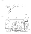
- Fig. 1 is a graph explaining a method for pressurizing a reservoir tank by an outlet pressure of a circulating pump of the present invention.
- Fig. 2 is a block diagram of a cooling system explaining an
embodiment 1 of the present invention. - Fig. 3 is a block diagram in the vicinity of the reservoir tank explaining an
embodiment 2 of the present invention. - Fig. 4 is a block diagram in the vicinity of the reservoir tank explaining an
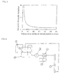
embodiment 3 of the present invention. - Fig. 5 is a graph showing a relation between a dissolving depth [m] of pressurizing gas and a pressure decrease rate [%].
- Fig. 6 is a diagram explaining a cooling system for a conventional superconducting cable.
-
- 1 Reservoir tank
- 1b Inner container of a reservoir tank
- 2 Liquid level of liquid nitrogen in a reservoir tank
- 3 Outlet of liquid nitrogen from a reservoir tank
- 4, 6, 9 Piping on a feeding side of a liquid nitrogen circulation
- 5 Circulating pump
- 5a Motor of a circulating pump
- 5b Extended shaft of a circulating pump
- 5c Fin
- 5e Vacuum container
- 7 Heat exchanger of a refrigerating machine
- 8 Refrigerating machine
- 10 Entrance of a superconducting power apparatus
- 11 Superconducting cable
- 12 Exit of a superconducting cable
- 13 Piping on a return side of a liquid nitrogen circulation
- 14 Piping for nitrogen return in a reservoir tank
- 15 Outlet of a return piping of a liquefied nitrogen gas
- 16, 18, 20 Branch piping for a pressurization
- 17 Evaporator
- 19 Valve
- 21 External piping for pressurization
- 22 High-pressure nitrogen cylinder
- 23 Heater inside a reservoir tank
- A cooling system for a superconducting power apparatus of the present invention will be described below in detail referring to attached drawings.
The cooling system for the superconducting power apparatus of the present invention comprises a reservoir tank for reserving a liquid gas, a circulating pump, a heat exchanger for cooling the liquid gas, and a circulating loop through which the liquefied gas circulates, for cooling the superconducting power apparatus by circulating the liquefied gas in a subcooled state using the circulating pump, further comprising a pressurizing means for pressurizing the reservoir tank with the same type of gas as the liquid gas, characterized in that a liquid level of the reservoir tank reserving the liquefied gas in a pressurized state is located above an outlet of a return piping of a liquefied nitrogen gas at least by a dissolving depth of pressurizing gas + (plus) a liquid-level movement correction amount. - A reason why it is necessary that the liquid level of the reservoir tank reserving the liquefied gas in the pressurized state is located above the outlet of a return piping of a liquefied nitrogen gas at least by a dissolving depth of the pressurizing gas + (plus) a liquid-level movement correction amount is described below.
A relation between a dissolving depth of a pressurizing gas and a pressure decrease rate was examined by experiments. Fig. 5 shows the relation between the pressurizing gas dissolving depth [m] and the pressure decrease rate [%]. - In Fig. 5, the dissolving depth of the pressurizing gas from a liquid level of a reservoir tank (that is, a pressurizing gas dissolving depth) is shown on a lateral axis and a decrease rate per hour of the pressure in the reservoir tank by liquefaction on a longitudinal axis, respectively.
As an experiment condition, an inner volume of the reservoir tank has a pressure of 0.3 MPa using a container with a diameter of 1 m and a height of 1 m.
As a result, as is clear from Fig. 5, a pressure decrease rate is remarkably large up to a dissolving depth of 10 cm, and the decrease of the pressurized pressure is still fast up to a dissolving depth of approximately 20 cm since a nitrogen gas in a gas phase used for pressurization is condensed into a liquid.
On the other hand, it is found out that if the dissolving depth is kept at 20 cm or more, a pressure decrease amount can be maintained at a small value of 1% or less.
Actually, since the liquid level is changed by influences of temperature, pressure and the like of liquid nitrogen besides the dissolving depth of the pressurizing gas, a liquid-level movement correction amount should be considered. - Therefore, it is necessary that the liquid level of the reservoir tank reserving the liquefied gas in the pressurized state is located above the outlet of a return piping of the liquefied nitrogen gas at least by the dissolving depth of the pressurizing gas + (plus) the liquid-level movement correction amount.
Specifically, an amount of 50 cm or more as the dissolving depth of the pressurizing gas (20 cm) + (plus) a liquid-level movement correction amount (30 cm) is preferable. The above hardly depends on a container shape of a reservoir tank, and a required depth is substantially this value even if a size of the reservoir tank is different.
Therefore, in a system of the present application, a height which can ensure the above-mentioned required depth (50 cm or more is preferable) is required as a container height of the reservoir tank. - As mentioned above, the present invention is to provide a system for cooling a superconducting power apparatus by a liquefied gas which can circulate liquefied gas in a subcooled state for a long time without a problem that a gas with a boiling point lower than the liquefied gas used for a pressurization is dissolved in the liquefied gas to cause an unstable factor for a circulation of the liquefied gas or trouble relating to an insulation of the power apparatus.
- The pressurizing means in the above-mentioned state comprises a pressurization of the liquefied gas in the reservoir tank to a predetermined pressure with the same type of gas as the liquefied gas reserved in the reservoir tank.
In order to prevent a liquefaction of a pressurizing gas from being cooled by a liquefied gas, a liquid level of a reservoir tank is located at a position higher than an outlet of a return piping to a circulating pump in the reservoir tank, at least by 20 cm or more, preferably by 50 cm or more. - Moreover, as pressurizing means in addition to the means for pressurizing with a high-pressure gas cylinder, there is another means for the pressurization by returning an output pressure of a circulating-pump, which is higher than the pressure in the reservoir tank.
As specific means using the pressure of the circulating pump outlet, there is means for branching an outlet piping of the circulating pump for pumping out a liquid from a reservoir tank and pressurizing and feeding it to a superconducting power apparatus.
By the branching piping, a part of the liquefied gas is taken out from an outlet of the circulating pump and is gasified by an evaporator and the gasified gas is returned to the reservoir tank through a pressure regulating valve which is opened or closed according to a pressure to maintain a pressure in the reservoir tank at a predetermined value. - In order to explain function of the present invention, a case where liquid nitrogen is used as a liquefied gas is described.
A boiling point of liquid nitrogen at an atmospheric pressure (1.013 MPa) is 77K. If this liquid nitrogen is pressurized to 0.3 MPa, the boiling point of the liquid nitrogen becomes 90K or above. Therefore, if the liquid nitrogen at 77K is pressurized to 0.3 MPa, the liquid nitrogen is brought into a subcooled state without generating any air bubbles.
The liquid outlet portion of a circulating pump is located at a bottom of a reservoir tank and connected to the circulating pump by a piping. - On the other hand, a return piping of a circulation is connected to the reservoir tank, and an outlet of the return piping of the circulation is located lower than a liquid level.
The liquefied gas sent out of the circulating pump cools a superconducting power apparatus and returns to the reservoir tank. At that time, since the outlet of the return piping is located at a position lower than a liquid level, the returning liquefied gas does not contact a pressurizing gas phase of the reservoir tank and moves to an outlet of the reservoir tank and further moves to the circulating pump and recirculates. - In the present invention, the liquid level is set higher than a predetermined height (20 cm) or more, from an outlet of a return piping of a liquefied nitrogen gas and an outlet of liquid nitrogen to a circulating pump (that is, a predetermined liquefied gas layer is provided).
And a temperature of the liquid nitrogen, located above the cool liquid nitrogen in a subcooled state at the respective outlets, gradually rises toward a surface of the liquid nitrogen in a reservoir tank and the temperature of the liquid nitrogen at the surface is substantially the same as a boiling temperature of a liquefied gas of 0.3 MPa.
In a prior art, there was a problem that if inside of a reservoir tank is pressurized by the same type of gas, the gas is liquefied and consumed and if the gas can't be supplied in time, then it may cause a drop of a pressure in the reservoir tank.
But in the present invention, by providing the liquefied gas layer in the reservoir tank, it is found out that the gas is hardly liquefied. - In the present invention, a pressurizing method other than a pressurizing by the high-pressure gas cylinder was examined. The method for pressurizing by its own piping pressure in the present invention will be described referring to Fig. 1.
Firstly, liquid nitrogen is pumped out from an inside of a reservoir tank in an atmospheric pressure state ("a" point in Fig. 1) and is fed by a circulating pump. At an outlet of the circulating pump, the liquid nitrogen flows at a rate of 50 L/min and is pressurized by 0.2 MPa ("b" point) with respect to the pressure at an inlet of the circulating pump.
In using a pressure of the outlet portion of the circulating pump, the liquid nitrogen branched from the outlet piping of the circulating pump is gasified by an evaporator at the middle point of the piping and returned to the reservoir tank so as to raise the pressure of the reservoir tank (arrow "c" in Fig. 1). - In response to that, an outlet pressure of the circulating pump is raised (arrow "d" in Fig. 1) and is capable of pressurizing a liquid gas in the reservoir tank all the time.
When a pressure in the reservoir tank exceeds ("e" point) an upper-limit set pressure (P2), a valve provided at the piping is closed, and a gas supply to the reservoir tank is stopped.
After that, in the reservoir tank, the nitrogen gas in a gas phase is cooled by the liquid nitrogen which temperature is below a triple point of the nitrogen gas, and the nitrogen gas in the gas phase is liquefied into a liquid nitrogen. And therefore, a pressure in the reservoir tank is decreased (arrow "f") because a gas volume is decreased by the liquefaction.
When the pressure reaches a lower-limit set pressure (P1) ("g" point), then the valve is opened, and a nitrogen gas is supplied into the reservoir tank by a pressure at a circulating pump outlet again, and a pressure in the reservoir tank is pressurized. - Flow of a low-temperature nitrogen gas through a piping might freeze the piping or valves. Therefore, an evaporator works to prevent it by gasifying the liquid nitrogen and raising the temperature to a room temperature.
As the evaporator, there are methods as winding a heater around the piping, passing the piping through water or the like, mounting a fin to the piping so as to raise a temperature by heat exchange with an outside air and the like.
As for the role of a valve, if the gas is continuously supplied merely by a branched piping from the outlet of the circulating pump, a pressure in a reservoir tank keeps on rising and there is a possibility to exceed a designed pressure of the reservoir tank.
Thus, the valve is closed to stop the pressurization by the gas when the pressure in the reservoir tank exceeds a predetermined pressure, while it is opened when the pressure falls under the predetermined pressure and resumes the pressurization so as to maintain a constant pressure in the reservoir tank automatically. - When a capacity of a reservoir tank is large, a large quantity of nitrogen gas is required for pressurization to a predetermined pressure. Thus, another nitrogen cylinder may be prepared to pressurize the pressure in the reservoir tank to a predetermined pressure.
Also, a method may be used that a heating device such as a heater is arranged at a gas phase portion inside the reservoir tank so as to pressurize and expand a gas in the reservoir tank.
The present invention will be described below in detail by means of embodiments. - Fig. 2 is a view showing an embodiment of a cooling system for a superconducting power apparatus of the present invention.
Liquid nitrogen is used as a liquefied gas. The liquid nitrogen is reserved in areservoir tank 1.
Thereservoir tank 1 is in a double-container structure, in which an insulating material is constructed between a double-container surrounding aninner container 1b and maintained in a vacuum state so as to reduce a heat intrusion. Moreover, the reservoir tank is a sealed container so that an inside of the reservoir tank can be pressurized. - At a bottom of the reservoir tank, an
outlet 3 of liquid from the reservoir tank connected to a circulating pump is provided, leading to an inlet of the circulatingpump 5 by a piping 4 with a diameter of 3 cm.
The circulatingpump 5 is a swirl rotary pump. Amotor 5a for rotating afin 5c and the fin are connected to each other by anextended shaft 5b of about 50 cm so as to restrict an inflow of heat by a transmission. - Moreover, the fin itself is arranged inside a vacuum container 5e so as to restrict a heat intrusion from an outside.
The rotary pump in the embodiment of the present invention has a rotation frequency of 50 Hz and is capable of a flow rate of 30 L/min as a liquid nitrogen flow rate and discharge a pressure of 0.2 MPa as a pressure difference between an inlet and an outlet of the circulating pump. The pump outlet is connected to a heat exchanger 7 of a refrigerating machine ahead by apiping 6 with a diameter of 3 cm. - The refrigerating machine 8 comprises a GM refrigerating machine or a Sterling refrigerating machine and has a heat exchanger connected to a low-temperature head creating frigidness for cooling a circulating liquid nitrogen to a low temperature.
In the present invention, the Sterling refrigerating machine having a refrigerating capacity of 1 kW is used, and when a liquid nitrogen of 30 L/min passes through the heat exchanger cooled by the refrigerating machine, 77K at an inlet of the refrigerating machine can be cooled to 74K. - The liquid nitrogen cooled by a refrigerating machine is connected to an
inlet 10 of a superconducting power apparatus by apiping 9 with a diameter of 3 cm in a water-tight manner.
In the cooling system for cooling thesuperconducting cable 11 of this embodiment, the superconducting cable is cooled by passage of liquid nitrogen, which is cooled by the refrigerating machine, in the superconducting cable.
The temperature of the liquid nitrogen having cooled the superconducting cable is raised but since the raised temperature is below a boiling point, a subcooled state without generation of air bubbles in the liquid nitrogen is maintained.
Therefore, a pressure loss is 0.1 MPa or less, which is sufficiently small even in a superconducting cable of 500 m, and the liquid nitrogen can be made to flow stably. - Also, since the liquid nitrogen without generating air bubbles soaks into an electric insulating layer of a superconducting cable, favorable electric insulation can be maintained.
The liquid nitrogen going out of anoutlet 12 of the superconducting cable returns to areservoir tank 1 by a piping 13 so as to form a circulation loop.
Thereservoir tank 1, the circulatingpump 2, theheat exchanger 3 of the refrigerating machine, the superconducting cable 4 and the nitrogen piping connecting these devices to each other are all in a double-container structure using vacuum heat insulation so as to reduce intruding heat from an outside. - The piping 13 returning to a reservoir tank is a piping 14 from an upper part of the reservoir tank to a bottom thereof for returning the liquid to the reservoir tank from an
outlet 15 of a return piping at a bottom portion of the tank. Anoutlet 3 of liquid nitrogen connected to the circulating pump is also located at a bottom of the reservoir tank.
During circulation, liquid nitrogen of the reservoir tank is reserved so that aliquid level 2 is located at a position higher than a position of theoutlet 15 at least by 20 cm. - By a method for pressurizing a reservoir tank by an outlet pressure of a circulating pump of the present invention, a
stainless piping 16 with a diameter of 6 mm is branched from apiping 6 of the pump outlet and the pressure of the liquid nitrogen there is taken out.
The liquid nitrogen flowing inside the piping 16 passes through anevaporator 17 after going out of a vacuum container of a circulating pump and all the liquid nitrogen is changed to a room temperature nitrogen gas. - As an evaporator, a 6 mm piping made of copper is wound in a 6 m coil configuration inside of a hot water container, is used in this embodiment. And the evaporator is soaked in hot water to raise a temperature of liquid nitrogen inside.
Any evaporators may be used only if liquid nitrogen inside can be made into a room-temperature gas, including a method in which a heater is wound around an outside of a coil, for example, to raise a temperature of the liquid nitrogen by heat generated by a heater or a method in which a fin is mounted on a piping for warming the liquid nitrogen by a heat exchange with an outside air.
A piping 18 coming out of theevaporator 17 is provided with avalve 19 having a pressure control function to flow a gas when an outlet pressure falls below a predetermined pressure and to stop the gas at a predetermined pressure or above. A piping 20 coming out of thevalve 19 is mounted at an upper part of a reservoir tank so as to pressurize the reservoir tank. - Since the
pipings evaporator 17 are at a room temperature, it is not necessary to make them into an insulating structure, but it is preferable on appearance that the piping 16 from the circulating pump outlet to the evaporator is surrounded by an insulating material such as a foaming urethane or the like to prevent a frost on thepiping 16.
If a valve operating at a low temperature is used for thevalve 19, a positions of thevalve 19 and theevaporator 17 can be switched, but a valve which is used in a low temperature is more expensive than that for a normal temperature and that is not an economical arrangement.
In this embodiment, the piping 16 for taking out pressure of the outlet of the circulating pump, branches from thepiping 6 at the pump outlet, but branching from a piping anywhere higher in the pressure than in the reservoir tank can achieve an object of the present invention, whether it branches from thepiping 9 at an outlet of a heat exchanger of a refrigerating machine or from aninlet portion 10 of a superconducting apparatus.
Thus, the pump outlet collectively refers to all portions of the piping which is downstream of the circulating pump outlet, not only to an immediate vicinity of the pump outlet. - In the
embodiment 1, a case where a circulating pump is located outside a reservoir tank is described, but the present invention can be also applied to a case where the circulating pump is located inside the reservoir tank.
Fig. 3 shows a view of a part of another mode of a cooling system for a superconducting power apparatus of the present invention. That is, Fig. 3 shows an extraction view of a reservoir tank portion of the cooling system to explain this embodiment.
In a circulatingpump 5, afin portion 5c for feeding liquid nitrogen is provided in a liquid of a reservoir tank, and a rotation of amotor 5a is transmitted by anextended shaft 5b.
The liquid nitrogen is pumped out from the reservoir tank, passes through apiping 6, goes out of the reservoir tank and is connected to a refrigerating machine for cooling the liquid nitrogen.
In this case, a piping for pressurization is mounted at a portion of thepiping 6, coming out of the reservoir tank, and returns to the reservoir tank through anevaporator 17 and avalve 19 as in theembodiment 1. - In the
embodiment 1, a pressurizing means for the reservoir tank is only by a gas from a circulating pump outlet. In this case, since the piping is as thin as 6 mm and has only a discharge pressure of the circulating pump, the gas supply is small and it takes an extremely long time to reach a predetermined pressure in the reservoir tank.
Particularly, if the reservoir tank is large, it takes several tens of hours. Then, as shown in Fig. 4, anexternal piping 21 is mounted to the reservoir tank as auxiliary means for supplying gas from a high-pressure nitrogen cylinder 22 or nitrogen curdle.
Moreover, since liquefaction is promoted when a gas phase portion inside the reservoir tank is cooled to a low temperature, aheater 23 may be arranged in a gas phase portion to restrain from the liquefaction. - According to the present invention, a cooling system for a superconducting power apparatus can be provided.
In the cooling system, a liquefied gas in a subcooled state is circulated for a long time, without an unstable factor of a circulation of the liquefied gas by dissolution of a gas with a boiling point lower than the liquefied gas used for pressurization, and without a trouble relating to an insulation of an electric apparatus.
Claims (6)
- A cooling system for a superconducting power apparatus comprising: a reservoir tank for reserving a liquefied gas; a circulating pump; a heat exchanger for cooling the liquefied gas; a circulation loop through which the liquefied gas is circulated, in which the superconducting power apparatus is cooled by circulating the liquefied gas in a subcooled state using the circulating pump; and
further comprising pressurizing means for pressurizing the liquefied gas in the reservoir tank with the same type of gas as the liquefied gas, wherein a liquid level in the reservoir tank for reserving the liquefied gas in a pressurized state is located above an outlet of a return piping of a circulating liquefied nitrogen gas at least by a dissolving depth of the pressurizing gas + (plus) a liquid level movement correction amount. - The cooling system for the superconducting power apparatus according to claim 1, wherein the pressurizing means for pressurizing the liquefied gas in the reservoir tank with the same type of gas as the liquefied gas performs pressurization at a predetermined pressure through a pressure regulating valve from a gas cylinder reserving the same type of gas as the liquefied gas at a high pressure.
- The cooling system for the superconducting power apparatus according to claim 1, wherein the pressurizing means for pressurizing the liquefied gas in the reservoir tank with the same type of gas as the liquefied gas comprising:a piping, which is branched from a piping from an outlet of the circulating pump to the superconducting power apparatus, and returns to the reservoir tank; andtherefore using a discharge pressure of the circulating pump which pumps out the liquefied gas in the subcooled state from the reservoir tank.
- The cooling system for the superconducting power apparatus according to claim 3, wherein the pressurizing means for pressurizing the liquefied gas in the reservoir tank with the same type of gas as the liquefied gas comprising:an evaporator for evaporating the liquefied gas; anda pressure regulating valve for regulating the pressure of the gas, wherein the evaporator and the pressure regulating valve are provided at the piping which is branched from a piping from an outlet of the circulating pump pumping out the liquefied gas in the subcooled state from the reservoir tank to the superconducting power apparatus, and returns to the reservoir tank.
- The cooling system for the superconducting power apparatus according to claim 3 or 4, wherein auxiliary means for the pressurizing means is further provided so that the same type of gas as the liquefied gas is supplied from a gas cylinder for the pressurization.
- The cooling system for the superconducting power apparatus according to any one of claims 1 to 5, wherein the auxiliary means for the pressurizing is further provided and the auxiliary means has a heating device arranged at a gas phase portion of the reservoir tank so as to heat and expand a volume of the gas at the phase portion in the reservoir tank.
Applications Claiming Priority (2)
| Application Number | Priority Date | Filing Date | Title |
|---|---|---|---|
| JP2004189117A JP4728601B2 (en) | 2004-06-28 | 2004-06-28 | Cooling system for superconducting power equipment |
| PCT/JP2005/010936 WO2006001203A1 (en) | 2004-06-28 | 2005-06-15 | Cooling system for superconducting power apparatus |
Publications (2)
| Publication Number | Publication Date |
|---|---|
| EP1780482A1 true EP1780482A1 (en) | 2007-05-02 |
| EP1780482A4 EP1780482A4 (en) | 2010-04-21 |
Family
ID=35779645
Family Applications (1)
| Application Number | Title | Priority Date | Filing Date |
|---|---|---|---|
| EP05751512A Withdrawn EP1780482A4 (en) | 2004-06-28 | 2005-06-15 | COOLING SYSTEM FOR SUPERCONDUCTING ELECTRICAL APPARATUS |
Country Status (6)
| Country | Link |
|---|---|
| US (1) | US20080202127A1 (en) |
| EP (1) | EP1780482A4 (en) |
| JP (1) | JP4728601B2 (en) |
| KR (1) | KR101142901B1 (en) |
| CN (1) | CN1969158B (en) |
| WO (1) | WO2006001203A1 (en) |
Cited By (1)
| Publication number | Priority date | Publication date | Assignee | Title |
|---|---|---|---|---|
| WO2013052354A1 (en) * | 2011-10-05 | 2013-04-11 | Varian Semiconductor Equipment Associates, Inc. | Techniques for sub-cooling in a superconducting system |
Families Citing this family (29)
| Publication number | Priority date | Publication date | Assignee | Title |
|---|---|---|---|---|
| JP2008053215A (en) * | 2006-07-24 | 2008-03-06 | Furukawa Electric Co Ltd:The | Superconducting wire, superconducting conductor and superconducting cable |
| WO2008015941A1 (en) * | 2006-08-02 | 2008-02-07 | The Furukawa Electric Co., Ltd. | Composite superconducting wire rod, method for manufacturing composite superconducting wire rod, and superconducting cable |
| KR100920883B1 (en) | 2008-01-25 | 2009-10-09 | 엘에스전선 주식회사 | Superconducting cable with improved cooling |
| US8280467B2 (en) | 2008-10-03 | 2012-10-02 | American Superconductor Corporation | Electricity transmission cooling system |
| KR101640607B1 (en) * | 2010-01-21 | 2016-07-19 | 엘에스전선 주식회사 | Cooling apparatus of superconduction cable line |
| DE102010028750B4 (en) * | 2010-05-07 | 2014-07-03 | Bruker Biospin Gmbh | Low-loss cryostat arrangement |
| DE102011002622A1 (en) * | 2011-01-13 | 2012-07-19 | Siemens Aktiengesellschaft | Cooling device for a superconductor and superconducting synchronous machine |
| CN103262179B (en) | 2011-02-25 | 2016-08-31 | 株式会社前川制作所 | superconducting cable cooling system |
| JP6046341B2 (en) * | 2011-12-14 | 2016-12-14 | 株式会社前川製作所 | Cooling device for superconducting power supply system |
| JP5916517B2 (en) * | 2012-05-29 | 2016-05-11 | 古河電気工業株式会社 | Cooling container |
| JP5991096B2 (en) * | 2012-09-07 | 2016-09-14 | 富士電機株式会社 | Method and apparatus for heating superconducting equipment |
| CN102881381A (en) * | 2012-09-27 | 2013-01-16 | 张家港韩中深冷科技有限公司 | Superconducting cable cooling system |
| JP6048647B2 (en) * | 2012-09-27 | 2016-12-21 | 住友電気工業株式会社 | Cooling system |
| WO2014104643A1 (en) * | 2012-12-26 | 2014-07-03 | Jeon Seung Chae | System for liquefied gas storage tank having ultra-low temperature and automatic flow path conversion valve for liquefied gas storage tank having ultra-low temperature |
| JP6180735B2 (en) * | 2012-12-26 | 2017-08-16 | 株式会社前川製作所 | Cooling system and cooling method for superconducting device |
| KR101388510B1 (en) * | 2013-05-23 | 2014-04-23 | 전승채 | Auto flow path selector valve for cryogenic storage tank |
| KR101368379B1 (en) * | 2012-12-26 | 2014-02-28 | 전승채 | Cryogenic storage tank system and auto flow path selector valve therefor |
| JP6084547B2 (en) * | 2013-10-18 | 2017-02-22 | ジャパンスーパーコンダクタテクノロジー株式会社 | Cryostat |
| KR101569650B1 (en) | 2015-03-25 | 2015-11-17 | 한국기계연구원 | Pressurization system using floating heater for cryogenic pressure vessel |
| JP2016217616A (en) * | 2015-05-20 | 2016-12-22 | 株式会社 フジヒラ | Cryogenic cooling device |
| KR102337181B1 (en) * | 2015-05-22 | 2021-12-09 | 한국전력공사 | Cooling system for superconducting machine |
| CN105402971B (en) * | 2016-01-07 | 2018-06-08 | 上海应用技术学院 | A kind of directional freezing device using liquid nitrogen |
| US10670189B2 (en) * | 2017-07-19 | 2020-06-02 | General Electric Company | Systems and methods for storing and distributing gases |
| FR3109986B1 (en) * | 2020-05-05 | 2022-05-06 | Eosgen Tech | COOLING SYSTEM, AIR CONDITIONING SYSTEM, ENGINE ASSEMBLY AND ASSOCIATED PROCESSES |
| US20210364230A1 (en) * | 2020-05-20 | 2021-11-25 | Air Liquide Advanced Technologies U.S. Llc | Method for cooling a system in the 120k to 200k range |
| CN114111082A (en) * | 2021-11-02 | 2022-03-01 | 深圳供电局有限公司 | A Subcooled Liquid Nitrogen Circulation System Based on GM Refrigerator |
| US20230295771A1 (en) * | 2022-03-16 | 2023-09-21 | Chengdu University Of Technology | Waste mercury recovery device |
| CN115435242A (en) * | 2022-08-29 | 2022-12-06 | 西安聚能医工科技有限公司 | A low-temperature medium self-circulation system for superconducting devices and its application |
| CN121206789A (en) * | 2025-11-26 | 2025-12-26 | 超滑科技(佛山)有限责任公司 | A liquid ammonia circulation device and a germanium spectrometer |
Family Cites Families (10)
| Publication number | Priority date | Publication date | Assignee | Title |
|---|---|---|---|---|
| JPS605868B2 (en) * | 1981-06-24 | 1985-02-14 | 日本真空技術株式会社 | Solenoid valve type automatic boosting low temperature refrigerant container |
| JPS62200099A (en) * | 1986-02-27 | 1987-09-03 | Mitsubishi Electric Corp | Very low temperature liquid supply system |
| DE3741145A1 (en) * | 1987-12-04 | 1989-06-15 | Deutsche Forsch Luft Raumfahrt | TREATMENT SYSTEM FOR LIQUID HYDROGEN |
| JP2712096B2 (en) * | 1991-03-30 | 1998-02-10 | 株式会社東芝 | Cryogenic liquid pumping method and apparatus |
| US5243821A (en) * | 1991-06-24 | 1993-09-14 | Air Products And Chemicals, Inc. | Method and apparatus for delivering a continuous quantity of gas over a wide range of flow rates |
| US5228295A (en) * | 1991-12-05 | 1993-07-20 | Minnesota Valley Engineering | No loss fueling station for liquid natural gas vehicles |
| US5954101A (en) * | 1996-06-14 | 1999-09-21 | Mve, Inc. | Mobile delivery and storage system for cryogenic fluids |
| JP3511288B2 (en) * | 2000-03-31 | 2004-03-29 | 大陽東洋酸素株式会社 | Superconducting material cooling device |
| JP2003336923A (en) * | 2002-05-20 | 2003-11-28 | Central Japan Railway Co | Cryogenic refrigeration equipment |
| US6865897B2 (en) * | 2003-07-10 | 2005-03-15 | Praxair Technology, Inc. | Method for providing refrigeration using capillary pumped liquid |
-
2004
- 2004-06-28 JP JP2004189117A patent/JP4728601B2/en not_active Expired - Fee Related
-
2005
- 2005-06-15 KR KR1020067019841A patent/KR101142901B1/en not_active Expired - Fee Related
- 2005-06-15 CN CN2005800196798A patent/CN1969158B/en not_active Expired - Fee Related
- 2005-06-15 US US11/630,889 patent/US20080202127A1/en not_active Abandoned
- 2005-06-15 EP EP05751512A patent/EP1780482A4/en not_active Withdrawn
- 2005-06-15 WO PCT/JP2005/010936 patent/WO2006001203A1/en not_active Ceased
Non-Patent Citations (2)
| Title |
|---|
| No further relevant documents disclosed * |
| See also references of WO2006001203A1 * |
Cited By (1)
| Publication number | Priority date | Publication date | Assignee | Title |
|---|---|---|---|---|
| WO2013052354A1 (en) * | 2011-10-05 | 2013-04-11 | Varian Semiconductor Equipment Associates, Inc. | Techniques for sub-cooling in a superconducting system |
Also Published As
| Publication number | Publication date |
|---|---|
| EP1780482A4 (en) | 2010-04-21 |
| CN1969158A (en) | 2007-05-23 |
| CN1969158B (en) | 2010-12-22 |
| KR101142901B1 (en) | 2012-05-10 |
| JP2006012654A (en) | 2006-01-12 |
| US20080202127A1 (en) | 2008-08-28 |
| KR20070036027A (en) | 2007-04-02 |
| WO2006001203A1 (en) | 2006-01-05 |
| JP4728601B2 (en) | 2011-07-20 |
Similar Documents
| Publication | Publication Date | Title |
|---|---|---|
| US20080202127A1 (en) | Cooling System for Superconducting Power Apparatus | |
| KR102053387B1 (en) | Device for cooling a consumer with a super-cooled liquid in a cooling circuit | |
| JP5313338B2 (en) | Device and method for pumping cryogenic fluid | |
| JP2008027780A (en) | Liquid refrigerant circulation cooling system | |
| EP1850354A1 (en) | Circulation cooling system for cryogenic cable | |
| US9835391B2 (en) | Heat recovery from a tunnel recooling process | |
| AU2012222562B2 (en) | Cooling device for cooling a superconductor, in particular in a magnetic resonance device or a rotor | |
| JP3648731B2 (en) | Cryogenic cooling system for cryogenic cables | |
| JP2859250B2 (en) | Superconducting member cooling device | |
| JP3511288B2 (en) | Superconducting material cooling device | |
| JP4686149B2 (en) | Cooling system using slush nitrogen | |
| JP4514346B2 (en) | Superconducting material cooling device | |
| KR102423639B1 (en) | A method and apparatus for cooling a load and a system comprising the corresponding apparatus and load | |
| JP4733842B2 (en) | Superconducting material cooling device | |
| JP2019075289A (en) | Apparatus and method for cooling superconductive cable | |
| JP6303246B2 (en) | Refrigerant circulation device and refrigerant circulation method | |
| US12331890B2 (en) | Cryogenic storage system | |
| JP2010177677A (en) | Cooling device for superconducting member | |
| KR102830446B1 (en) | Low-temperature fluid conveying unit, low-temperature fluid conveying method, and device having low-temperature fluid conveying unit | |
| RU2767668C1 (en) | Cryosystem of an aviation integrated electric power plant based on hts | |
| JP2026032669A (en) | Superconducting coil device | |
| JP2005183440A (en) | Superconducting material cooling device | |
| WO2016037809A1 (en) | Superconducting magnet device including a cryogenic cooling bath and cooling pipes | |
| CA2013108C (en) | Beverage cooling and pumping system | |
| CN121143478A (en) | Liquid filling system and control method of liquid filling system |
Legal Events
| Date | Code | Title | Description |
|---|---|---|---|
| PUAI | Public reference made under article 153(3) epc to a published international application that has entered the european phase |
Free format text: ORIGINAL CODE: 0009012 |
|
| 17P | Request for examination filed |
Effective date: 20070126 |
|
| AK | Designated contracting states |
Kind code of ref document: A1 Designated state(s): FR |
|
| DAX | Request for extension of the european patent (deleted) | ||
| RBV | Designated contracting states (corrected) |
Designated state(s): FR |
|
| A4 | Supplementary search report drawn up and despatched |
Effective date: 20100318 |
|
| 17Q | First examination report despatched |
Effective date: 20100802 |
|
| RAP1 | Party data changed (applicant data changed or rights of an application transferred) |
Owner name: THE FURUKAWA ELECTRIC CO., LTD. |
|
| STAA | Information on the status of an ep patent application or granted ep patent |
Free format text: STATUS: THE APPLICATION HAS BEEN WITHDRAWN |
|
| 18W | Application withdrawn |
Effective date: 20150213 |