EP1780098A1 - Elektrische Servolenkungsvorrichtung vom Riementyp - Google Patents
Elektrische Servolenkungsvorrichtung vom Riementyp Download PDFInfo
- Publication number
- EP1780098A1 EP1780098A1 EP06255118A EP06255118A EP1780098A1 EP 1780098 A1 EP1780098 A1 EP 1780098A1 EP 06255118 A EP06255118 A EP 06255118A EP 06255118 A EP06255118 A EP 06255118A EP 1780098 A1 EP1780098 A1 EP 1780098A1
- Authority
- EP
- European Patent Office
- Prior art keywords
- washer
- housing
- gearbox housing
- belt
- power steering
- Prior art date
- Legal status (The legal status is an assumption and is not a legal conclusion. Google has not performed a legal analysis and makes no representation as to the accuracy of the status listed.)
- Granted
Links
- 230000005540 biological transmission Effects 0.000 description 4
- 230000008878 coupling Effects 0.000 description 4
- 238000010168 coupling process Methods 0.000 description 4
- 238000005859 coupling reaction Methods 0.000 description 4
- 230000002093 peripheral effect Effects 0.000 description 3
- 239000012141 concentrate Substances 0.000 description 1
- 239000000463 material Substances 0.000 description 1
- 239000007769 metal material Substances 0.000 description 1
Images



Classifications
-
- B—PERFORMING OPERATIONS; TRANSPORTING
- B62—LAND VEHICLES FOR TRAVELLING OTHERWISE THAN ON RAILS
- B62D—MOTOR VEHICLES; TRAILERS
- B62D5/00—Power-assisted or power-driven steering
- B62D5/04—Power-assisted or power-driven steering electrical, e.g. using an electric servo-motor connected to, or forming part of, the steering gear
- B62D5/0421—Electric motor acting on or near steering gear
- B62D5/0424—Electric motor acting on or near steering gear the axes of motor and final driven element of steering gear, e.g. rack, being parallel
-
- B—PERFORMING OPERATIONS; TRANSPORTING
- B62—LAND VEHICLES FOR TRAVELLING OTHERWISE THAN ON RAILS
- B62D—MOTOR VEHICLES; TRAILERS
- B62D5/00—Power-assisted or power-driven steering
- B62D5/02—Power-assisted or power-driven steering mechanical, e.g. using a power-take-off mechanism for taking power from a rotating shaft of the vehicle and applying it to the steering gear
-
- B—PERFORMING OPERATIONS; TRANSPORTING
- B62—LAND VEHICLES FOR TRAVELLING OTHERWISE THAN ON RAILS
- B62D—MOTOR VEHICLES; TRAILERS
- B62D5/00—Power-assisted or power-driven steering
- B62D5/04—Power-assisted or power-driven steering electrical, e.g. using an electric servo-motor connected to, or forming part of, the steering gear
- B62D5/0442—Conversion of rotational into longitudinal movement
- B62D5/0445—Screw drives
- B62D5/0448—Ball nuts
-
- F—MECHANICAL ENGINEERING; LIGHTING; HEATING; WEAPONS; BLASTING
- F16—ENGINEERING ELEMENTS AND UNITS; GENERAL MEASURES FOR PRODUCING AND MAINTAINING EFFECTIVE FUNCTIONING OF MACHINES OR INSTALLATIONS; THERMAL INSULATION IN GENERAL
- F16H—GEARING
- F16H7/00—Gearings for conveying rotary motion by endless flexible members
- F16H7/08—Means for varying tension of belts, ropes or chains
- F16H7/10—Means for varying tension of belts, ropes or chains by adjusting the axis of a pulley
- F16H7/14—Means for varying tension of belts, ropes or chains by adjusting the axis of a pulley of a driving or driven pulley
Definitions
- the present invention relates to a belt-type electric power steering apparatus.
- Embodiments of the present invention relate to a belt-type electric power steering apparatus, in which a motor pulley housing and a gearbox housing are coupled by bolts and release of the bolts is prevented, thereby preventing the droop of the motor pulley housing.
- a hydraulic pump which is a power source assisting power for the hydraulic steering apparatus, is operated by an engine of a vehicle, and always consumes energy regardless of the rotation of a steering wheel.
- an electric power steering apparatus on the other hand, if a steering wheel rotates and generates torque, an electric motor which is operated by electric energy provides steering assistant power. Therefore, when the electric power steering apparatus is used, it is possible to improve energy efficiency in comparison with the hydraulic power steering apparatus.
- a conventional electric power steering apparatus includes a steering system 100 extending from a steering wheel 101 to both wheels 108, and an assistant power mechanism 120 for providing steering power.
- the steering system 100 includes a steering shaft having an end connected to the steering wheel 101 to rotate along with the steering wheel 101, and the other end connected to a pinion shaft 104 by a pair of universal joints 103. Further, the pinion shaft 104 is connected to a rack bar 109 through a rack and pinion mechanism 105, while both ends of the rack bar 109 are connected to both wheels of the vehicle by tie rods 106 and knuckle arms 107, respectively.
- the rack and pinion mechanism 105 has a pinion gear 111 mounted on the pinion shaft 104, and a rack gear 112 mounted on a peripheral surface of one end of the rack bar 109 and engaged with the pinion gear 111.
- torque is generated in the steering system 100 and causes the rack and pinion mechanism 105 and the tie rods 106 to steer the wheels 108.
- the assistant power mechanism 120 includes a torque sensor 121 for sensing torque applied to the steering wheel 101 by the driver, so as to output an electric signal in proportion to the sensed torque, an electronic control unit 123 for generating a control signal depending on the electric signal transmitted from the torque sensor 121, an electric motor 130 for generating steering power according to the control signal transmitted from the electronic control unit 123, and a belt-type power transmission apparatus 140 for transmitting the assistant power, generated by the electric motor 130, to the rack bar 109 through the belt.
- a torque sensor 121 for sensing torque applied to the steering wheel 101 by the driver, so as to output an electric signal in proportion to the sensed torque
- an electronic control unit 123 for generating a control signal depending on the electric signal transmitted from the torque sensor 121
- an electric motor 130 for generating steering power according to the control signal transmitted from the electronic control unit 123
- a belt-type power transmission apparatus 140 for transmitting the assistant power, generated by the electric motor 130, to the rack bar 109 through the belt.
- the torque generated by the rotation of the steering wheel 101 is transmitted through the rack and pinion mechanism 105 to the rack bar 109.
- the assistant steering power which the electric motor 130 generates depending on the generated torque is transmitted by the belt-type power transmission apparatus through a ball screw 150 to the rack bar 109.
- the rack bar is moved along an axis thereof by the torque generated in the steering system 100 and the assistant power generated by the electric motor 130.
- the conventional power steering apparatus for the vehicle includes the rack bar 109 extending across the vehicle and having the rack gear mounted on an outer peripheral surface thereof, the pinion shaft 104 having the pinion gear engaged with the rack gear, the ball screw unit 150 having balls 210, a ball screw 203, and a ball nut 205 engaged with the ball screw 203 through the balls 201, the belt-type power transmission apparatus 140 connecting the ball nut 205 to the shaft 221 of the electric motor, and the electric motor 130.
- a motor pulley housing 240 encloses the electric motor and is fixed to a gearbox housing 250 by a bolt coupling.
- the pinion shaft 104 is connected to the steering wheel through the steering shaft, and the rack bar 109 having the screw formed by a predetermined length at one end thereof is contained in a rack housing 223.
- the ball screw unit 150 includes the ball nut 205 formed to be coaxial with the rack bar 109 and enclosing the rack bar 109, and the balls 201 arranged on the outer peripheral surface of the rack bar 109 and contacting the ball screw 203.
- the ball nut 205 rotates as the motor shaft 221 rotates.
- a bearing 207 is interposed between the outer surface of the ball nut 205 and the inner surface of the rack housing 223 in order for the ball nut 205 to rotate smoothly.
- the belt type power transmission apparatus 140 includes a belt 230 connecting the motor shaft 221 to the ball nut 205, and transmits steering power generated from the electric motor 130 in proportion to the steering torque applied to the steering wheel to the rack bar 109 through the ball nut 205.
- the ball nut 205 rotates by receiving the rotational force of the motor shaft 221 through the belt 230.
- the rack bar 109 moves linearly in a direction of the axis of the rack bar 109.
- FIG. 3 is a side view showing a motor pulley housing and gearbox housing for the conventional electric power steering apparatus of the vehicle.
- the motor is fixed to the gearbox housing 250 by coupling the motor pulley housing 240 to the gearbox housing 250 using the bolts.
- the body has curved elongate guide holes to allow tensioning, and the bolts secure it in as selected position.
- the motor 221 rotates to operate the belt 230, causing the ball nut 205 to rotate.
- the tension of the belt 230 is applied to the motor shaft 221 and the rack bar 109 provided with the ball nut 205 so that the force of the motor shaft 221 and the rack bar 109 pulls the motor shaft 221 and the rack bar 109 toward each other.
- the force concentrates on the bolt coupling portion of the pulley housing 240 and the gearbox housing 250 which is mechanically weakened.
- the motor shaft 221 rotates while generating vibration and impact, etc. which may cause loosening of the bolts.
- the motor shaft 221 moves in a direction to the rack bar 105 provided with the ball nut 205 so as to reduce the tension of the belt 230, thereby causing noise between the belt 230 and the pulley, as well as damaging the belt 230.
- a belt type electric power steering apparatus comprising: a gearbox housing enclosing a rack gear and a ball screw; a motor pulley housing coupled to the gearbox housing and enclosing an electric motor; a belt for transmitting rotational force of the electric motor to a rack bar; and locking washers interposed between bolt heads and the gearbox housing, for preventing loosening of bolts when the motor pulley housing is coupled to the gearbox housing.
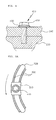
- FIG. 4 the combination of a motor pulley housing 240 and a gearbox housing 250 by means of bolts is shown, in which a locking washer 430 is interposed between a bolt head 410 and the gearbox housing 250.
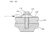
- the tension of the belt 230 causes force to be applied to the motor pulley housing 240, mounted on and fixed to the gearbox housing 250 by means of the bolts, in a direction marked by an arrow in FIG. 5B.
- the first prominence 500 is formed at both edges of a curved elongate guide hole 350 in order to prevent the movement of the motor pulley housing 240 in the direction marked by the arrow in FIG. 5B.
- a block-shaped washer 510 is disposed between the bolt head 410 and the gearbox housing 250, and has the second prominence 530 formed on a surface thereof, and a hole for the bolt formed at a center portion thereof.
- the locking washer 430 is interposed between the bolt head 410 and the block-shaped washer 510 so as to prevent movement of the motor pulley housing 240 by the first prominence 500 formed at both edges of the bolt guide hole 350 of the gearbox 250 and the second prominence 530 formed on the block-shaped washer 510. Further, the locking washer 430 is interposed between the bolt head 410 and the block-shaped washer 510, so as to prevent the bolt 400 from being loosened due to vibrations generated during the operation of the vehicle.
- the washers are generally used to prevent the bolt head or nut from damaging the object to be coupled caused by the coupling force of the bolt or nut, or to prevent the coupled bolt or nut from being loosened by mechanical vibrations.
- Doughnut-shaped plane washers made of a metal material are generally used as washers to prevent the damage of the material.
- C-type spring washer 600 made by cutting a portion of a coil spring, a disc spring washer 610 with a disc shape, an inner tooth washer 620 with inner teeth formed on an inner periphery thereof, an outer tooth washer 630 with outer teeth formed on an outer periphery thereof, inner and outer tooth washer 640 with inner and outer teeth formed on inner and outer peripheries thereof, and a disc washer 650 with prominence formed on an outer periphery thereof, are mainly used as washers 40 to prevent the release of the bolts.
- the motor pulley housing is coupled to the gearbox housing by using the locking washers and the like, thereby making it possible to prevent the release of the bolts and the movement of the motor shaft to the rack bar with the ball nut.
- the motor pulley housing is coupled to the gearbox housing by using the locking washers and the like, thereby making it possible to prevent the release of the bolts and the movement of the motor shaft to the rack bar with the ball nut.
Landscapes
- Engineering & Computer Science (AREA)
- Mechanical Engineering (AREA)
- Chemical & Material Sciences (AREA)
- Combustion & Propulsion (AREA)
- Transportation (AREA)
- General Engineering & Computer Science (AREA)
- Power Steering Mechanism (AREA)
- Bolts, Nuts, And Washers (AREA)
Applications Claiming Priority (1)
| Application Number | Priority Date | Filing Date | Title |
|---|---|---|---|
| KR1020050100983A KR100723731B1 (ko) | 2005-10-25 | 2005-10-25 | 벨트 타입 전동식 동력 보조 조향장치 |
Publications (2)
| Publication Number | Publication Date |
|---|---|
| EP1780098A1 true EP1780098A1 (de) | 2007-05-02 |
| EP1780098B1 EP1780098B1 (de) | 2008-11-26 |
Family
ID=37591513
Family Applications (1)
| Application Number | Title | Priority Date | Filing Date |
|---|---|---|---|
| EP06255118A Not-in-force EP1780098B1 (de) | 2005-10-25 | 2006-10-04 | Elektrische Servolenkungsvorrichtung vom Riementyp |
Country Status (6)
| Country | Link |
|---|---|
| US (1) | US20070095603A1 (de) |
| EP (1) | EP1780098B1 (de) |
| JP (1) | JP4440912B2 (de) |
| KR (1) | KR100723731B1 (de) |
| CN (1) | CN100471747C (de) |
| DE (1) | DE602006003836D1 (de) |
Families Citing this family (11)
| Publication number | Priority date | Publication date | Assignee | Title |
|---|---|---|---|---|
| PL2383167T3 (pl) * | 2010-04-27 | 2014-05-30 | Thyssenkrupp Presta Ag | Sposób sterowania układem kierowniczym |
| KR101452557B1 (ko) * | 2011-08-16 | 2014-10-21 | 주식회사 만도 | 전동식 동력 보조 조향장치 |
| EP2799309A4 (de) * | 2011-12-26 | 2015-05-06 | Toyota Motor Co Ltd | Elektrische servolenkvorrichtung |
| JPWO2015056782A1 (ja) | 2013-10-17 | 2017-03-09 | 塩野義製薬株式会社 | 新規アルキレン誘導体 |
| CN103697045A (zh) * | 2013-12-31 | 2014-04-02 | 江苏金铁人自动化科技有限公司 | 一种预紧装置 |
| KR102318622B1 (ko) * | 2017-07-24 | 2021-10-27 | 현대모비스 주식회사 | 상용차용 조향장치 |
| CN107489684A (zh) * | 2017-07-31 | 2017-12-19 | 合肥江淮朝柴动力有限公司 | 一种螺栓防松垫片 |
| JP6677693B2 (ja) * | 2017-10-20 | 2020-04-08 | ファナック株式会社 | 電動機装置 |
| JP6648912B1 (ja) * | 2019-09-09 | 2020-02-14 | 近畿刃物工業株式会社 | 切断加工用刃物 |
| EP3834969A1 (de) * | 2019-12-11 | 2021-06-16 | Hilti Aktiengesellschaft | Vorrichtung zur drehmomentübertragung von einem bohrgerät auf eine bohrkrone |
| JP6681560B1 (ja) * | 2020-01-10 | 2020-04-15 | 近畿刃物工業株式会社 | 切込生成刃 |
Citations (2)
| Publication number | Priority date | Publication date | Assignee | Title |
|---|---|---|---|---|
| US20050079939A1 (en) * | 2003-10-09 | 2005-04-14 | Simmons Stanley R. | Belt tensioner and method |
| US20050121251A1 (en) * | 2003-05-06 | 2005-06-09 | Nsk Ltd. | Belt speed reducing apparatus for electric power steering apparatus and electric power steering apparatus |
Family Cites Families (9)
| Publication number | Priority date | Publication date | Assignee | Title |
|---|---|---|---|---|
| US179931A (en) * | 1876-07-18 | Improvement in nut-locks | ||
| US747459A (en) * | 1903-05-16 | 1903-12-22 | Conrad Miller | Nut-lock. |
| US1580015A (en) * | 1923-12-03 | 1926-04-06 | Glen G Clark | Lock washer |
| US3221792A (en) * | 1963-04-08 | 1965-12-07 | Illinois Tool Works | Lockwasher and fastener assembly |
| US3858804A (en) * | 1972-08-28 | 1975-01-07 | Hixson R M | Rail fastening assembly |
| GB1547089A (en) * | 1977-03-02 | 1979-06-06 | Chloride Group Ltd | Battery terminals |
| GB2349119B (en) * | 1999-04-21 | 2001-05-30 | Breed Automotive Tech | A sensor for a seat belt retractor |
| KR20020023925A (ko) * | 2001-12-29 | 2002-03-29 | 홍성기 | 파형 스프링 와셔 파형 형상과 기능 |
| KR20050106701A (ko) * | 2004-05-06 | 2005-11-11 | 현대자동차주식회사 | 체결용 너트 |
-
2005
- 2005-10-25 KR KR1020050100983A patent/KR100723731B1/ko not_active Expired - Fee Related
-
2006
- 2006-10-04 EP EP06255118A patent/EP1780098B1/de not_active Not-in-force
- 2006-10-04 DE DE602006003836T patent/DE602006003836D1/de active Active
- 2006-10-06 US US11/544,540 patent/US20070095603A1/en not_active Abandoned
- 2006-10-17 JP JP2006282972A patent/JP4440912B2/ja not_active Expired - Fee Related
- 2006-10-24 CN CNB2006101320680A patent/CN100471747C/zh not_active Expired - Fee Related
Patent Citations (2)
| Publication number | Priority date | Publication date | Assignee | Title |
|---|---|---|---|---|
| US20050121251A1 (en) * | 2003-05-06 | 2005-06-09 | Nsk Ltd. | Belt speed reducing apparatus for electric power steering apparatus and electric power steering apparatus |
| US20050079939A1 (en) * | 2003-10-09 | 2005-04-14 | Simmons Stanley R. | Belt tensioner and method |
Also Published As
| Publication number | Publication date |
|---|---|
| KR100723731B1 (ko) | 2007-05-30 |
| US20070095603A1 (en) | 2007-05-03 |
| DE602006003836D1 (de) | 2009-01-08 |
| CN1958371A (zh) | 2007-05-09 |
| JP2007118937A (ja) | 2007-05-17 |
| JP4440912B2 (ja) | 2010-03-24 |
| KR20070044731A (ko) | 2007-04-30 |
| EP1780098B1 (de) | 2008-11-26 |
| CN100471747C (zh) | 2009-03-25 |
Similar Documents
| Publication | Publication Date | Title |
|---|---|---|
| EP1886899A1 (de) | Elektrische Servolenkung mit einem Mechanismus zur Einstellung der Spannung eines Riemens | |
| JP3613693B2 (ja) | 電動式舵取装置 | |
| KR101452557B1 (ko) | 전동식 동력 보조 조향장치 | |
| EP1780098B1 (de) | Elektrische Servolenkungsvorrichtung vom Riementyp | |
| KR101568953B1 (ko) | 차량 조향 시스템 트랜스미션 | |
| KR100621347B1 (ko) | 자동차의 전기식 동력 보조 조향 장치 | |
| US20120216645A1 (en) | Worm wheel | |
| EP1813508B1 (de) | Lenkvorrichtung | |
| US5213173A (en) | Electric power steering apparatus | |
| EP1783031B1 (de) | Elektrische Fahrzeugservolenkung mit Riemengetriebe | |
| EP1792804A1 (de) | Von einem Motor angetriebene Servolenkung für ein Fahrzeug mit einer Vorrichtung zur Einstellung der Spannung eines Treibriemens | |
| EP1777140A1 (de) | Riemenspanner für eine elektrische Servolenkung mit Riemenantrieb | |
| KR102408739B1 (ko) | 랙구동형 동력 보조 조향장치 | |
| KR101085336B1 (ko) | 세레이션이 형성된 댐핑 커플러를 구비한 자동차의 전기식동력 보조 조향장치 | |
| JP4909874B2 (ja) | ウォームギヤ機構を備えた電動パワーステアリング装置 | |
| KR101218866B1 (ko) | 랙 타입 전동식 동력 보조 조향장치 | |
| JP2006051913A (ja) | 電動パワーステアリング装置 | |
| KR20170031342A (ko) | 전동식 동력 보조 조향장치 | |
| JPH1148995A (ja) | 電動式パワーステアリング装置 | |
| KR20070044732A (ko) | 벨트 타입 전동식 동력 보조 조향장치 | |
| KR20060035873A (ko) | 전동식 파워 스티어링 장치의 감속기 유격흡수구조 | |
| JPH04123875U (ja) | 電動式動力舵取装置 | |
| JPH045168A (ja) | 電動式動力舵取装置 | |
| KR102242944B1 (ko) | 랙 타입 전동식 동력 보조 조향장치 |
Legal Events
| Date | Code | Title | Description |
|---|---|---|---|
| PUAI | Public reference made under article 153(3) epc to a published international application that has entered the european phase |
Free format text: ORIGINAL CODE: 0009012 |
|
| AK | Designated contracting states |
Kind code of ref document: A1 Designated state(s): AT BE BG CH CY CZ DE DK EE ES FI FR GB GR HU IE IS IT LI LT LU LV MC NL PL PT RO SE SI SK TR |
|
| AX | Request for extension of the european patent |
Extension state: AL BA HR MK YU |
|
| RIN1 | Information on inventor provided before grant (corrected) |
Inventor name: NAMGUNG, JOO Inventor name: JO, HEEGWON |
|
| 17P | Request for examination filed |
Effective date: 20071029 |
|
| AKX | Designation fees paid |
Designated state(s): DE FR GB IT |
|
| GRAP | Despatch of communication of intention to grant a patent |
Free format text: ORIGINAL CODE: EPIDOSNIGR1 |
|
| GRAS | Grant fee paid |
Free format text: ORIGINAL CODE: EPIDOSNIGR3 |
|
| GRAA | (expected) grant |
Free format text: ORIGINAL CODE: 0009210 |
|
| AK | Designated contracting states |
Kind code of ref document: B1 Designated state(s): DE FR GB IT |
|
| REG | Reference to a national code |
Ref country code: GB Ref legal event code: FG4D |
|
| REF | Corresponds to: |
Ref document number: 602006003836 Country of ref document: DE Date of ref document: 20090108 Kind code of ref document: P |
|
| PLBE | No opposition filed within time limit |
Free format text: ORIGINAL CODE: 0009261 |
|
| STAA | Information on the status of an ep patent application or granted ep patent |
Free format text: STATUS: NO OPPOSITION FILED WITHIN TIME LIMIT |
|
| 26N | No opposition filed |
Effective date: 20090827 |
|
| PGFP | Annual fee paid to national office [announced via postgrant information from national office to epo] |
Ref country code: IT Payment date: 20091031 Year of fee payment: 4 |
|
| REG | Reference to a national code |
Ref country code: FR Ref legal event code: ST Effective date: 20100630 |
|
| PG25 | Lapsed in a contracting state [announced via postgrant information from national office to epo] |
Ref country code: FR Free format text: LAPSE BECAUSE OF NON-PAYMENT OF DUE FEES Effective date: 20091102 |
|
| GBPC | Gb: european patent ceased through non-payment of renewal fee |
Effective date: 20101004 |
|
| PG25 | Lapsed in a contracting state [announced via postgrant information from national office to epo] |
Ref country code: GB Free format text: LAPSE BECAUSE OF NON-PAYMENT OF DUE FEES Effective date: 20101004 |
|
| PG25 | Lapsed in a contracting state [announced via postgrant information from national office to epo] |
Ref country code: IT Free format text: LAPSE BECAUSE OF NON-PAYMENT OF DUE FEES Effective date: 20101004 |
|
| PGFP | Annual fee paid to national office [announced via postgrant information from national office to epo] |
Ref country code: DE Payment date: 20190820 Year of fee payment: 14 |
|
| REG | Reference to a national code |
Ref country code: DE Ref legal event code: R119 Ref document number: 602006003836 Country of ref document: DE |
|
| PG25 | Lapsed in a contracting state [announced via postgrant information from national office to epo] |
Ref country code: DE Free format text: LAPSE BECAUSE OF NON-PAYMENT OF DUE FEES Effective date: 20210501 |