EP1777985A1 - Kopfhörer mit verbesserter Ohrpassstück-Aufhängung - Google Patents
Kopfhörer mit verbesserter Ohrpassstück-Aufhängung Download PDFInfo
- Publication number
- EP1777985A1 EP1777985A1 EP05450176A EP05450176A EP1777985A1 EP 1777985 A1 EP1777985 A1 EP 1777985A1 EP 05450176 A EP05450176 A EP 05450176A EP 05450176 A EP05450176 A EP 05450176A EP 1777985 A1 EP1777985 A1 EP 1777985A1
- Authority
- EP
- European Patent Office
- Prior art keywords
- flat spring
- earpiece
- headband
- headphones
- flat
- Prior art date
- Legal status (The legal status is an assumption and is not a legal conclusion. Google has not performed a legal analysis and makes no representation as to the accuracy of the status listed.)
- Granted
Links
- 239000000725 suspension Substances 0.000 title description 5
- 239000004020 conductor Substances 0.000 claims description 4
- 238000009413 insulation Methods 0.000 claims 1
- 230000006978 adaptation Effects 0.000 description 14
- 239000006260 foam Substances 0.000 description 8
- 229920001971 elastomer Polymers 0.000 description 7
- 239000000463 material Substances 0.000 description 7
- 239000002775 capsule Substances 0.000 description 5
- 239000012528 membrane Substances 0.000 description 5
- 238000004873 anchoring Methods 0.000 description 4
- 238000005266 casting Methods 0.000 description 3
- 238000002347 injection Methods 0.000 description 3
- 239000007924 injection Substances 0.000 description 3
- 239000012212 insulator Substances 0.000 description 3
- 230000002687 intercalation Effects 0.000 description 3
- 238000009830 intercalation Methods 0.000 description 3
- 239000000243 solution Substances 0.000 description 3
- 230000002452 interceptive effect Effects 0.000 description 2
- 238000004519 manufacturing process Methods 0.000 description 2
- 230000010355 oscillation Effects 0.000 description 2
- 229910000906 Bronze Inorganic materials 0.000 description 1
- 241000446313 Lamella Species 0.000 description 1
- 229920005830 Polyurethane Foam Polymers 0.000 description 1
- 229910000831 Steel Inorganic materials 0.000 description 1
- 239000011324 bead Substances 0.000 description 1
- 239000010974 bronze Substances 0.000 description 1
- 238000010276 construction Methods 0.000 description 1
- KUNSUQLRTQLHQQ-UHFFFAOYSA-N copper tin Chemical compound [Cu].[Sn] KUNSUQLRTQLHQQ-UHFFFAOYSA-N 0.000 description 1
- 238000013016 damping Methods 0.000 description 1
- 210000005069 ears Anatomy 0.000 description 1
- 230000000694 effects Effects 0.000 description 1
- 239000003292 glue Substances 0.000 description 1
- 230000002045 lasting effect Effects 0.000 description 1
- 230000010358 mechanical oscillation Effects 0.000 description 1
- 239000004033 plastic Substances 0.000 description 1
- 229920003023 plastic Polymers 0.000 description 1
- 239000004814 polyurethane Substances 0.000 description 1
- 239000012858 resilient material Substances 0.000 description 1
- 230000035945 sensitivity Effects 0.000 description 1
- 238000005476 soldering Methods 0.000 description 1
- 230000005236 sound signal Effects 0.000 description 1
- 238000005507 spraying Methods 0.000 description 1
- 239000010959 steel Substances 0.000 description 1
- 238000004073 vulcanization Methods 0.000 description 1
Images


Classifications
-
- H—ELECTRICITY
- H04—ELECTRIC COMMUNICATION TECHNIQUE
- H04R—LOUDSPEAKERS, MICROPHONES, GRAMOPHONE PICK-UPS OR LIKE ACOUSTIC ELECTROMECHANICAL TRANSDUCERS; DEAF-AID SETS; PUBLIC ADDRESS SYSTEMS
- H04R1/00—Details of transducers, loudspeakers or microphones
- H04R1/10—Earpieces; Attachments therefor ; Earphones; Monophonic headphones
- H04R1/1058—Manufacture or assembly
- H04R1/1066—Constructional aspects of the interconnection between earpiece and earpiece support
-
- H—ELECTRICITY
- H04—ELECTRIC COMMUNICATION TECHNIQUE
- H04R—LOUDSPEAKERS, MICROPHONES, GRAMOPHONE PICK-UPS OR LIKE ACOUSTIC ELECTROMECHANICAL TRANSDUCERS; DEAF-AID SETS; PUBLIC ADDRESS SYSTEMS
- H04R1/00—Details of transducers, loudspeakers or microphones
- H04R1/10—Earpieces; Attachments therefor ; Earphones; Monophonic headphones
- H04R1/1008—Earpieces of the supra-aural or circum-aural type
-
- H—ELECTRICITY
- H04—ELECTRIC COMMUNICATION TECHNIQUE
- H04R—LOUDSPEAKERS, MICROPHONES, GRAMOPHONE PICK-UPS OR LIKE ACOUSTIC ELECTROMECHANICAL TRANSDUCERS; DEAF-AID SETS; PUBLIC ADDRESS SYSTEMS
- H04R5/00—Stereophonic arrangements
- H04R5/033—Headphones for stereophonic communication
- H04R5/0335—Earpiece support, e.g. headbands or neckrests
Definitions
- the invention relates to headphones comprising a headband and at least one earpiece, which surrounds an electroacoustic converter, where the earpiece and the headband are parts of the headphones which can be moved with respect to each other.
- the headphone earpiece must cover the ear, particularly the external auditory channel, with a good seal against the environment to be able to screen out interfering noises that come from the outside.
- This requirement which applies both to supraural and circumaural headphones, must be simultaneously satisfied regardless of different head shapes and sizes.
- different solutions have been proposed in the technological field.
- AT 370 275 B discloses headphones whose headband can be telescoped along an arched contour. Such headphones can be adapted to different head sizes, but the shape of the head in the area of the ears is not taken into account.
- AT 338 350 B discloses headphones which are provided with an elastic band in the headband area, a solution which also only allows adaptations to head size.
- Headphones which deal with adaptation of the location and the position of the earpieces to the different user head shapes, are known, for example, from AT 368 823 B .
- the headphone earpiece is attached to an elastic rubber band, which is clamped as a chord on the yoke-shaped holder, allowing adaptation to a given head shape by slanting the position of the earpiece at the attachment point.
- the elastic band is here attached with its end to the holder.
- the earpiece is pressed in the direction of the yoke-shaped holder, resulting in tension being applied to the band and the loss of the necessary capacity for adaptation. In this case as well, the result is that the earpiece is not applied against the ear with a sufficient seal.
- AT 321 388 discloses headphones in which the earpieces, with respect to the headband, can be swivel about the axes which are perpendicular with respect to the plane formed by the headband, and can thus be adapted to the slanted position of the ear or application surfaces of the earpiece from the broadest place of the head tapering to the chin.
- spring-mounted elements are provided whose purpose is to increase the wearer's comfort.
- the earpieces are here attached to the ends of the headband with the intercalation of spring action element in the direction of the application movement. No provision is made for adaptation to head shape, which generally tapers in the forward direction.
- CH 112 106 discloses headphones where, at each one of the headband ends, supports made of a resilient material are provided. The headphones are attached to a rubber band, which is clamped between the ends of the arc-shaped supports. As in the above AT 386 823 , such an arrangement does not produce even application pressure on the application surface of the ear.
- GB 2 304 488 discloses headphones whose earpieces can be shifted along an end area of the headband. This shifting is achieved by the intercalation of a spring. Thus, the earpiece can be moved with respect to the headband in only one direction, which does not provide wearer comfort and provides even less adaptability to different head shapes.
- AT 217 105 B discloses headphones whose spring-mounted headband presents, at its two ends, straight sections on which the earpieces are arranged in a manner which allows them to be shifted. There are no other possibilities provided for moving the earpieces with respect to the headband.
- AT 297 111 B provides a multi-part headband with articulations in whose interior a threaded spring is provided which determines the extent to which the articulations can be swiveled with respect to each other and which generates the application pressure.
- the wearer's comfort and the adaptation to different head shapes are considerably restricted by this arrangement.
- the state of the art also provides cardan joints as the attachment of the headphone earpieces to the headband.
- the earpiece here can be swiveled about one or two mutually inclined axes, which allows adaptation to head shape; however, this solution is associated with problems, such as, for example, large space requirement and complicated design. Jamming occurs consistently; for example, when rotation about a given axis is desired, the earpiece is rotated about the other axis in an undesired manner due to jamming.
- a cardanic support is disclosed for example in AT 322 651 A .
- the patent WO 99/14981 A1 which does not refer to the generic object [headphones] in question, relates to a microphone, whose microphone capsule is connected by a holder to the microphone housing. To lower the sensitivity to mechanical oscillations, the holder is made of bendable arms that are, made of elastic rubber material.
- This patent addresses an entirely different purpose, namely the uncoupling of the microphone capsule from external interfering influences, and it does not relate at all to the adaptation and homogeneous pressure application on different shapes. Moreover, the latter purpose cannot be achieved at all using such a capsule attachment.
- Another device is also known, which is based on a similar principle, that uncouples oscillations between a loudspeaker cover and its housing which is designed as a loudspeaker box.
- bars are provided on the front surface of the housing, which form a labyrinth like pattern and act as leaf springs connecting the cover with the housing front.
- headphones which, on the one hand, can be adapted to different head sizes and shapes and, on the other hand, provide a spatially constant application pressure along the circumference and the circumferential area of the headphone earpiece, in other words along the application surface.
- Appropriate attachment of the earpiece must have a long service life and must not constitute a weak place of the headphones.
- the requirements of a space saving design, as well as of a simple and cost advantageous manufacture, must be met.
- the earpiece is connected with the headband by at least three arms which together form a flat spring and which point in different directions within the flat defined by the flat spring.
- the expression flat springs generally relates to spring types that have a flat structure, whose return force acts substantially, perpendicularly to the spring surface under a load.
- the flat build up by the flat spring can either be planar, arched, or curved.
- Flat springs particularly include planar or arched disks, whose properties are additionally influenced by perforations or recesses; band springs, combinations of partial spring elements, which set up the flat, for example, band, spiral or lamellar springs which start from or are patterned starting from a central area to form a star or spiral shape; in addition, springs, which are called plate springs in the state of the art, present lamellas or corrugations which are concentric in a cross section of the lamellar disk.
- the circumference or outline of the flat springs can have any possible contours, such as circular, oval, elliptical, rectangular, square, polygonal, etc.
- a flat spring can consist of a single piece or multiple pieces with several partial springs in a flat
- the earpiece has all the degrees of freedom which are required for the placement on the head and the adaptation to the head shape. All these degrees of freedom are spring loaded by two-dimensional anchoring of the flat spring.
- An important advantage is that a homogeneous application pressure is achieved, which completely prevents the generation of unpleasant and painful pressure places in the area of the ear.
- An attachment according to the invention can be mounted cost advantageously and rapidly. There are no jamming, squeaking or mutually abutting components, and the flat construction shape of the attachment is extremely space saving.
- the earpiece and the headband represent parts that are movable with respect to each other, where one of these movable parts is firmly connected with the circumferential area of the flat spring, while the other movable part is anchored in the middle area of the flat spring.
- the central area of the flat spring is delimited by the inner ends of the at least three arms, and the circumferential area is clamped or defined by the external ends of the arms. Starting from the central area, the arms point in different directions, so that two-dimensional suspension is achieved.
- the flat spring functions also simultaneously as the contact for the electroacoustic converter.
- Several conductors can be applied either on a flat spring which is designed as a single part, or a flat spring consisting of several parts where the partial springs are made of conductive material form the contacting poles.
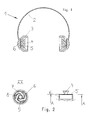
- FIG. 1 shows headphones 1 according to the invention which comprises a headband 2, headphone earpieces 3 and electroacoustic converters 4, which are integrated in the earpieces.
- the attachment between the earpiece 3, which is movable relative to the headband 2, and the headband 2 itself consists of a flat spring 5.
- the latter is attached along its entire circumference area in a dish-shaped recess 6, which is provided on the headband 2.
- the flat spring 5 is not directly connected to the earpiece 3, rather by means of an electroacoustic converter 4, as an intermediate piece.
- Such an embodiment is represented in Figure 6; here the flat spring engages as a continuation of the earpiece, while the converter sits inside the earpiece.
- Figure 2 shows the invention in detail, where the earpiece has been omitted to improve the figure clarity.
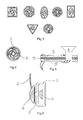
- the flat spring is designed as a circular thin disk, in which the recesses 7 are provided which define three longitudinal spiral-shaped arms 8, and extend from the central area to the circumferential area of the flat springs 5.
- the central area of the flat spring is characterized by an internal ring, in which the cylindrical continuation of the converter housing is inserted and anchored.
- at least three arms 8 are required to achieve the anchoring of the flat spring with flexibility in two dimensions.
- the flat spring is preferably oriented substantially parallel to the application surface of the earpiece.
- the plane which is clamped by its circumference or its circumferential area is preferred for the plane which is clamped by its circumference or its circumferential area to be substantially parallel to the application surface.
- the application surface here corresponds to the external surface of the earpiece which is applied against the ear when the headphones are worn.
- the attachment points of the arms 8 on the internal ring and on the circumferential ring are preferably arranged at regular intervals from each other, for example, substantially as the apexes of an equilateral triangle, a square or, in general, an equilateral polygon, resulting in a particularly homogeneous application pressure when the headphones are worn.
- the attachment points of the arms 8 must not coincide at one point, rather they must be separated slightly from each other.
- an imaginary circumferential area should be considered to lie under the circumference of the flat spring, where the area is clamped by the given external ends of the arms 8.
- An internal ring design should also be considered a preferred embodiment, because it functions simultaneously to receive the electroacoustic converter. However, the internal ends of the arms are also attached directly to the converter or to the earpiece.
- the circumferential area of the flat spring to engage with the earpiece, optionally with the intercalation of the converter, and for the middle area of the flat spring to be anchored to the headband or to a recess which is provided for that purpose and connected with the headband.
- the materials from which the flat springs are constructed preferably consist of resilient steel sheets, elastic plastics, spring bronze or resilient FlexPrint material on which it is possible to apply conductors for the contacting with the electroacoustic converter.
- the arms 8 which form the flat spring 5 can also consist of tightly clamped rubber bands or of threaded springs (Figure 7) whose function as tension springs is to clamp to the earpieces, preferably spanning an angle of approximately 120° with respect to each other.
- the flat spring consists of one piece and it is connected with the electroacoustic converter 4.
- the attachment according to the invention can be taken into consideration directly, by integrating the area of the flat spring to which the converter is to be attached in the injection casting mold, and it is enclosed by spraying during injection casting with the appropriate converter housing.
- the arms of the attachment according to the invention can be used if the spring material is conductive, as connection lines leading to the headphone cable.
- the flat spring consists of two partial springs, which are electrically insulated from each other. As shown in Figure 4, the flat spring at its circumference and its internal ring, which serves as a recess for the loudspeaker, is cut in each case at two places.
- An additional possibility consists in using a multilayer spring, which consists two electrically conductive flat springs 9, 9' which are arranged in parallel on top of each other, and which are separated by a preferably elastically deformable insulator 10.
- the damping properties of the entire system, which consists of two flat springs can be established by the mechanical properties of the deformable insulator. As a result, the return force can be adapted exactly to the weight of the earpiece.
- Examples of materials for use as spring insulators are, among others, PU (polyurethane) foam, whose components are applied to the spring surface, for example, with metering needles, gel-like cold glue or rubber material which is applied by vulcanization.
- the multilayer spring is contacted at the top side and at the bottom side.
- the conductive flat springs 9, 9' are thus part of the electrical contact of the converter and they connect the inputs at the converter with the headphone cable or, in the case of radio headphones, with the reception unit.
- the contacting is represented schematically in Figure 5 with wire lines which start from soldering places at the springs.
- electrically conductive accessories can be provided, so that, in all possible variants, the conducting of the sound signal from the headband to the converter can be omitted. The contacting of the converter thus occurs through the flat spring.
- the individual arms 8 can also be present as individual partial springs, which are separated from each other, and they form the flat spring according to the invention, as a result of their flat arrangement.
- the effect is the same as that achieved with the flat spring consisting of a single piece.
- the special design of the headband itself does not play a role that is essential for the invention; thus, additionally, the recess for the flat spring can be arranged on the headband in such a manner that it can be shifted longitudinally, for example, for adaptation to different head sizes.
- headphones are known in the field, in which an earpiece is provided for only one ear, which is often the case with headsets, that is headphones which are also equipped with a microphone. Such variants are naturally considered to fall within the scope of the invention.
- the two-dimensional suspension is essential with regard to the headband. Whether the circumferential area is designed as such and recognizable, for example, as a ring, is of secondary importance. Thus, the external ends of the arms 8 can be attached directly to the recess 6 for the flat spring, instead of transitioning into the circumferential ring.
- Figure 8 shows a flat spring, which consists of an arm 11 which starts from the circumferential area and runs in a spiral pattern around the central area, where the end of the arm opens in a recess for the converter or for the earpiece.
- a homogeneous application pressure is not guaranteed, because the attachment is more or less one dimensional.
- Figure 9 shows an attachment by means of a holohedral flat spring, which is preferably designed over its entire surface as a rubber membrane 12, with a fixed zone 13 in the middle, on which the converter 4 is mounted, and a bead 14 on the margin, which is firmly connected with the recess on the headband.
- the membrane is connected along its entire circumference with a recess on the headband.
- a two-dimensional anchoring of the earpiece is also achieved, making it possible to generate homogeneous application pressure. Because of the increasing brittleness of the membrane and because of the required high membrane tension, which must remain the same over a long time period, the latter arrangement represents a less preferred possible attachment for the earpiece.
- Figure 10 and 11 show headphones, in which the attachment of the earpiece 3 consists of foam.
- the earpiece 3 or the converter 4 is here anchored on a plate 15, which is applied against a foam pad 16 and connected with the latter.
- the foam pad in the represented embodiment example, fills a recess 17 which is attached on the headband.
- different areas of the foam pad 16 are compressed to varying degrees.
- the homogeneous application pressure of the earpiece on the ear is again achieved.
- anchor the converter 4 or the earpiece 3 directly without intermediate plate 15 in the foam bed.
- the earpieces 3 also consist of foam, which already results in a low capacity for adaptation.
- the earpiece can be tilted as a whole, even before the deformability of the earpiece itself comes into play. This is also achieved by the fact that a foam bed is provided behind the earpiece, that is between the earpiece and the headband.
Landscapes
- Engineering & Computer Science (AREA)
- Manufacturing & Machinery (AREA)
- Physics & Mathematics (AREA)
- Acoustics & Sound (AREA)
- Signal Processing (AREA)
- Headphones And Earphones (AREA)
Priority Applications (5)
| Application Number | Priority Date | Filing Date | Title |
|---|---|---|---|
| EP05450176A EP1777985B1 (de) | 2005-10-21 | 2005-10-21 | Kopfhörer mit verbesserter Ohrpassstück-Aufhängung |
| DE602005010713T DE602005010713D1 (de) | 2005-10-21 | 2005-10-21 | Kopfhörer mit verbesserter Ohrpassstück-Aufhängung |
| AT05450176T ATE413080T1 (de) | 2005-10-21 | 2005-10-21 | Kopfhörer mit verbesserter ohrpassstück- aufhängung |
| JP2006258161A JP2007116681A (ja) | 2005-10-21 | 2006-09-25 | ヘッドホン |
| US11/583,992 US20070092098A1 (en) | 2005-10-21 | 2006-10-19 | Headphones with elastic earpiece interface |
Applications Claiming Priority (1)
| Application Number | Priority Date | Filing Date | Title |
|---|---|---|---|
| EP05450176A EP1777985B1 (de) | 2005-10-21 | 2005-10-21 | Kopfhörer mit verbesserter Ohrpassstück-Aufhängung |
Publications (2)
| Publication Number | Publication Date |
|---|---|
| EP1777985A1 true EP1777985A1 (de) | 2007-04-25 |
| EP1777985B1 EP1777985B1 (de) | 2008-10-29 |
Family
ID=36691363
Family Applications (1)
| Application Number | Title | Priority Date | Filing Date |
|---|---|---|---|
| EP05450176A Expired - Lifetime EP1777985B1 (de) | 2005-10-21 | 2005-10-21 | Kopfhörer mit verbesserter Ohrpassstück-Aufhängung |
Country Status (5)
| Country | Link |
|---|---|
| US (1) | US20070092098A1 (de) |
| EP (1) | EP1777985B1 (de) |
| JP (1) | JP2007116681A (de) |
| AT (1) | ATE413080T1 (de) |
| DE (1) | DE602005010713D1 (de) |
Cited By (2)
| Publication number | Priority date | Publication date | Assignee | Title |
|---|---|---|---|---|
| WO2016148786A1 (en) * | 2015-03-17 | 2016-09-22 | Koss Corporation | Personal acoustic systems and flexible earpiece mounts for the same |
| FR3106247A1 (fr) * | 2020-01-15 | 2021-07-16 | Florent RONDEAU | casque audio et procédé de pose d’un tel casque sur la tête d’un utilisateur |
Families Citing this family (13)
| Publication number | Priority date | Publication date | Assignee | Title |
|---|---|---|---|---|
| WO2009076649A2 (en) * | 2007-12-12 | 2009-06-18 | Semcken Kevin R | Headphone apparatus |
| DK2498509T3 (en) | 2008-04-07 | 2018-11-12 | Koss Corp | Wireless headset with switching between wireless networks |
| US20140261436A1 (en) * | 2011-10-27 | 2014-09-18 | Koninklijke Philips N.V. | Patient interface that engaes the sides of the head |
| JP5910119B2 (ja) * | 2012-01-31 | 2016-04-27 | ソニー株式会社 | ヘッドホン |
| US9635447B2 (en) | 2012-07-17 | 2017-04-25 | Innovation Sound Technology Co., Ltd. | Earpiece casing cavity and corresponding earphone |
| GB2512105B (en) * | 2013-03-20 | 2019-04-03 | B & W Group Ltd | Headphones with flexibly mounted earpiece |
| JP6292089B2 (ja) * | 2014-09-02 | 2018-03-14 | 株式会社Jvcケンウッド | ヘッドバンド及び頭部装着機器 |
| WO2016077247A1 (en) * | 2014-11-10 | 2016-05-19 | The Quest Group | Headphone suspension system |
| US20160249126A1 (en) * | 2015-02-20 | 2016-08-25 | Harman International Industries, Inc. | Personalized headphones |
| US9749727B2 (en) * | 2015-06-18 | 2017-08-29 | Plantronics, Inc. | Folding headset earpiece |
| US9756412B1 (en) | 2016-02-09 | 2017-09-05 | Apple Inc. | Circumaural to supra-aural convertible headphone earcups |
| US10573291B2 (en) | 2016-12-09 | 2020-02-25 | The Research Foundation For The State University Of New York | Acoustic metamaterial |
| US10462574B1 (en) * | 2018-11-30 | 2019-10-29 | Google Llc | Reinforced actuators for distributed mode loudspeakers |
Citations (15)
| Publication number | Priority date | Publication date | Assignee | Title |
|---|---|---|---|---|
| CH112106A (de) | 1924-07-30 | 1925-10-01 | Theo Dr Volk | Kopffernhörer. |
| AT217105B (de) | 1960-03-17 | 1961-09-11 | Akg Akustische Kino Geraete | Kopfhörer mit federndem Bügel |
| GB1229086A (de) * | 1968-11-21 | 1971-04-21 | ||
| AT297111B (de) | 1970-04-08 | 1972-03-10 | Akg Akustische Kino Geraete | Bügel für Kopfhörer |
| US3795919A (en) * | 1971-06-21 | 1974-03-12 | Y Aho | Method of joining a hearing protector and a protective helmet and device for applying same |
| AT321388B (de) | 1973-06-01 | 1975-03-25 | A K G Akustische U Kino Geraet | Kopfhörer |
| AT322651B (de) | 1973-05-18 | 1975-06-10 | Akg Akustische Kino Geraete | Anordnung fur kopfhörer |
| AT338350B (de) | 1975-11-28 | 1977-08-25 | Akg Akustische Kino Geraete | Elastisches kopfband fur kopfhorer |
| AT368823B (de) | 1980-08-07 | 1982-11-10 | Akg Akustische Kino Geraete | Gelenkige verbindung, insbesondere fuer kopfhoerer |
| AT370275B (de) | 1981-03-05 | 1983-03-10 | Akg Akustische Kino Geraete | Kopfhoererbuegel |
| GB2304488A (en) | 1995-08-17 | 1997-03-19 | Sony Corp | Cordless headphones' earpieces are spring-biassed to retracted position, operate on/off switch |
| DE19711708A1 (de) | 1997-03-20 | 1998-10-01 | Sennheiser Electronic | Kopfbandlose Kopfträgereinheit |
| WO1999014981A1 (de) | 1997-09-18 | 1999-03-25 | Akg Acoustics Gmbh | Mikrophon |
| US20030169898A1 (en) * | 2001-10-23 | 2003-09-11 | Pioneer Corporation | Headphone device |
| US20040213428A1 (en) * | 2003-01-31 | 2004-10-28 | Hugo Lenhard-Backhaus | Headphone |
Family Cites Families (2)
| Publication number | Priority date | Publication date | Assignee | Title |
|---|---|---|---|---|
| US4058688A (en) * | 1975-05-27 | 1977-11-15 | Matsushita Electric Industrial Co., Ltd. | Headphone |
| JP4470845B2 (ja) * | 2005-09-05 | 2010-06-02 | ソニー株式会社 | ヘッドホン及びヘッドホン載置装置 |
-
2005
- 2005-10-21 DE DE602005010713T patent/DE602005010713D1/de not_active Expired - Lifetime
- 2005-10-21 EP EP05450176A patent/EP1777985B1/de not_active Expired - Lifetime
- 2005-10-21 AT AT05450176T patent/ATE413080T1/de not_active IP Right Cessation
-
2006
- 2006-09-25 JP JP2006258161A patent/JP2007116681A/ja not_active Withdrawn
- 2006-10-19 US US11/583,992 patent/US20070092098A1/en not_active Abandoned
Patent Citations (15)
| Publication number | Priority date | Publication date | Assignee | Title |
|---|---|---|---|---|
| CH112106A (de) | 1924-07-30 | 1925-10-01 | Theo Dr Volk | Kopffernhörer. |
| AT217105B (de) | 1960-03-17 | 1961-09-11 | Akg Akustische Kino Geraete | Kopfhörer mit federndem Bügel |
| GB1229086A (de) * | 1968-11-21 | 1971-04-21 | ||
| AT297111B (de) | 1970-04-08 | 1972-03-10 | Akg Akustische Kino Geraete | Bügel für Kopfhörer |
| US3795919A (en) * | 1971-06-21 | 1974-03-12 | Y Aho | Method of joining a hearing protector and a protective helmet and device for applying same |
| AT322651B (de) | 1973-05-18 | 1975-06-10 | Akg Akustische Kino Geraete | Anordnung fur kopfhörer |
| AT321388B (de) | 1973-06-01 | 1975-03-25 | A K G Akustische U Kino Geraet | Kopfhörer |
| AT338350B (de) | 1975-11-28 | 1977-08-25 | Akg Akustische Kino Geraete | Elastisches kopfband fur kopfhorer |
| AT368823B (de) | 1980-08-07 | 1982-11-10 | Akg Akustische Kino Geraete | Gelenkige verbindung, insbesondere fuer kopfhoerer |
| AT370275B (de) | 1981-03-05 | 1983-03-10 | Akg Akustische Kino Geraete | Kopfhoererbuegel |
| GB2304488A (en) | 1995-08-17 | 1997-03-19 | Sony Corp | Cordless headphones' earpieces are spring-biassed to retracted position, operate on/off switch |
| DE19711708A1 (de) | 1997-03-20 | 1998-10-01 | Sennheiser Electronic | Kopfbandlose Kopfträgereinheit |
| WO1999014981A1 (de) | 1997-09-18 | 1999-03-25 | Akg Acoustics Gmbh | Mikrophon |
| US20030169898A1 (en) * | 2001-10-23 | 2003-09-11 | Pioneer Corporation | Headphone device |
| US20040213428A1 (en) * | 2003-01-31 | 2004-10-28 | Hugo Lenhard-Backhaus | Headphone |
Cited By (9)
| Publication number | Priority date | Publication date | Assignee | Title |
|---|---|---|---|---|
| WO2016148786A1 (en) * | 2015-03-17 | 2016-09-22 | Koss Corporation | Personal acoustic systems and flexible earpiece mounts for the same |
| RU2657691C1 (ru) * | 2015-03-17 | 2018-06-14 | Косс Корпорейшн | Персональные акустические системы и гибкие элементы крепления наушников для них |
| US10136210B2 (en) | 2015-03-17 | 2018-11-20 | Koss Corporation | Personal acoustic systems and flexible earpiece mounts for the same |
| US10531176B2 (en) | 2015-03-17 | 2020-01-07 | Koss Corporation | Personal acoustic systems and flexible earpiece mounts for the same |
| US10959014B2 (en) | 2015-03-17 | 2021-03-23 | Koss Corporation | Personal acoustic systems and flexible earpiece mounts for the same |
| US11477565B2 (en) | 2015-03-17 | 2022-10-18 | Koss Corporation | Personal acoustic systems and flexible earpiece mounts for the same |
| US11671743B2 (en) | 2015-03-17 | 2023-06-06 | Koss Corporation | Personal acoustic systems and flexible earpiece mounts for the same |
| FR3106247A1 (fr) * | 2020-01-15 | 2021-07-16 | Florent RONDEAU | casque audio et procédé de pose d’un tel casque sur la tête d’un utilisateur |
| WO2021144520A1 (fr) * | 2020-01-15 | 2021-07-22 | Rondeau Florent | Casque audio et procédé de pose d'un tel casque sur la tête d'un utilisateur |
Also Published As
| Publication number | Publication date |
|---|---|
| JP2007116681A (ja) | 2007-05-10 |
| EP1777985B1 (de) | 2008-10-29 |
| DE602005010713D1 (de) | 2008-12-11 |
| US20070092098A1 (en) | 2007-04-26 |
| ATE413080T1 (de) | 2008-11-15 |
Similar Documents
| Publication | Publication Date | Title |
|---|---|---|
| EP1777985B1 (de) | Kopfhörer mit verbesserter Ohrpassstück-Aufhängung | |
| EP2320674B1 (de) | Ohrenschutz-Headset für Zweiwegkommunikation | |
| US8233655B2 (en) | Headphone | |
| JP3520531B2 (ja) | ヘッドホン装置 | |
| US7580541B2 (en) | Personal audio-set with adjustable sliding ear clip mount | |
| EP1518440B1 (de) | Kopfsprechhörer | |
| US5469505A (en) | Communications headset having a ball joint-mounted receiver assembly | |
| RU2611215C1 (ru) | Внутриушной наушник (варианты) и способ их ношения | |
| CN113940096A (zh) | 人体工学耳机设备 | |
| US20170289666A1 (en) | Audio headset, in particular for the practice of sport | |
| EP2475188A2 (de) | Automatische anpassende Kopfhörer | |
| JP2011114512A (ja) | ヘッドホルダーを用いた骨伝導ヘッドホン | |
| JP2007534201A (ja) | 後頭部ヘッドバンド付きヘッドホン | |
| CN1980487B (zh) | 骨传导头戴式耳机 | |
| US10334352B2 (en) | Headphone pivot joint | |
| JP2008510081A (ja) | 聴力保護部材及び/又はスピーカ部材 | |
| JP4063172B2 (ja) | ヘッドホン | |
| CN214381330U (zh) | 一种骨传导耳机的接触式组装机构 | |
| JP6601689B2 (ja) | 骨伝導ヘッドセット | |
| US20060239447A1 (en) | Earphone with selectable cable positioning | |
| JP4137608B2 (ja) | ヘッドセット | |
| CN223437158U (zh) | 一种耳机 | |
| CN221948333U (zh) | 一种耳挂结构及耳机 | |
| CN221151546U (zh) | 头戴式耳机外壳及头戴式耳机 | |
| WO2005067654A2 (en) | Personal audio-set with adjustable sliding ear clip mount |
Legal Events
| Date | Code | Title | Description |
|---|---|---|---|
| PUAI | Public reference made under article 153(3) epc to a published international application that has entered the european phase |
Free format text: ORIGINAL CODE: 0009012 |
|
| AK | Designated contracting states |
Kind code of ref document: A1 Designated state(s): AT BE BG CH CY CZ DE DK EE ES FI FR GB GR HU IE IS IT LI LT LU LV MC NL PL PT RO SE SI SK TR |
|
| AX | Request for extension of the european patent |
Extension state: AL BA HR MK YU |
|
| 17P | Request for examination filed |
Effective date: 20071025 |
|
| AKX | Designation fees paid |
Designated state(s): AT BE BG CH CY CZ DE DK EE ES FI FR GB GR HU IE IS IT LI LT LU LV MC NL PL PT RO SE SI SK TR |
|
| GRAP | Despatch of communication of intention to grant a patent |
Free format text: ORIGINAL CODE: EPIDOSNIGR1 |
|
| GRAS | Grant fee paid |
Free format text: ORIGINAL CODE: EPIDOSNIGR3 |
|
| GRAA | (expected) grant |
Free format text: ORIGINAL CODE: 0009210 |
|
| AK | Designated contracting states |
Kind code of ref document: B1 Designated state(s): AT BE BG CH CY CZ DE DK EE ES FI FR GB GR HU IE IS IT LI LT LU LV MC NL PL PT RO SE SI SK TR |
|
| REG | Reference to a national code |
Ref country code: GB Ref legal event code: FG4D |
|
| REG | Reference to a national code |
Ref country code: CH Ref legal event code: EP |
|
| REG | Reference to a national code |
Ref country code: IE Ref legal event code: FG4D |
|
| REF | Corresponds to: |
Ref document number: 602005010713 Country of ref document: DE Date of ref document: 20081211 Kind code of ref document: P |
|
| NLV1 | Nl: lapsed or annulled due to failure to fulfill the requirements of art. 29p and 29m of the patents act | ||
| LTIE | Lt: invalidation of european patent or patent extension |
Effective date: 20081029 |
|
| PG25 | Lapsed in a contracting state [announced via postgrant information from national office to epo] |
Ref country code: ES Free format text: LAPSE BECAUSE OF FAILURE TO SUBMIT A TRANSLATION OF THE DESCRIPTION OR TO PAY THE FEE WITHIN THE PRESCRIBED TIME-LIMIT Effective date: 20090209 Ref country code: BG Free format text: LAPSE BECAUSE OF FAILURE TO SUBMIT A TRANSLATION OF THE DESCRIPTION OR TO PAY THE FEE WITHIN THE PRESCRIBED TIME-LIMIT Effective date: 20090129 Ref country code: LT Free format text: LAPSE BECAUSE OF FAILURE TO SUBMIT A TRANSLATION OF THE DESCRIPTION OR TO PAY THE FEE WITHIN THE PRESCRIBED TIME-LIMIT Effective date: 20081029 |
|
| PG25 | Lapsed in a contracting state [announced via postgrant information from national office to epo] |
Ref country code: NL Free format text: LAPSE BECAUSE OF FAILURE TO SUBMIT A TRANSLATION OF THE DESCRIPTION OR TO PAY THE FEE WITHIN THE PRESCRIBED TIME-LIMIT Effective date: 20081029 Ref country code: LV Free format text: LAPSE BECAUSE OF FAILURE TO SUBMIT A TRANSLATION OF THE DESCRIPTION OR TO PAY THE FEE WITHIN THE PRESCRIBED TIME-LIMIT Effective date: 20081029 Ref country code: PL Free format text: LAPSE BECAUSE OF FAILURE TO SUBMIT A TRANSLATION OF THE DESCRIPTION OR TO PAY THE FEE WITHIN THE PRESCRIBED TIME-LIMIT Effective date: 20081029 Ref country code: PT Free format text: LAPSE BECAUSE OF FAILURE TO SUBMIT A TRANSLATION OF THE DESCRIPTION OR TO PAY THE FEE WITHIN THE PRESCRIBED TIME-LIMIT Effective date: 20090330 Ref country code: SI Free format text: LAPSE BECAUSE OF FAILURE TO SUBMIT A TRANSLATION OF THE DESCRIPTION OR TO PAY THE FEE WITHIN THE PRESCRIBED TIME-LIMIT Effective date: 20081029 Ref country code: FI Free format text: LAPSE BECAUSE OF FAILURE TO SUBMIT A TRANSLATION OF THE DESCRIPTION OR TO PAY THE FEE WITHIN THE PRESCRIBED TIME-LIMIT Effective date: 20081029 Ref country code: IS Free format text: LAPSE BECAUSE OF FAILURE TO SUBMIT A TRANSLATION OF THE DESCRIPTION OR TO PAY THE FEE WITHIN THE PRESCRIBED TIME-LIMIT Effective date: 20090228 |
|
| PG25 | Lapsed in a contracting state [announced via postgrant information from national office to epo] |
Ref country code: RO Free format text: LAPSE BECAUSE OF FAILURE TO SUBMIT A TRANSLATION OF THE DESCRIPTION OR TO PAY THE FEE WITHIN THE PRESCRIBED TIME-LIMIT Effective date: 20081029 Ref country code: EE Free format text: LAPSE BECAUSE OF FAILURE TO SUBMIT A TRANSLATION OF THE DESCRIPTION OR TO PAY THE FEE WITHIN THE PRESCRIBED TIME-LIMIT Effective date: 20081029 Ref country code: BE Free format text: LAPSE BECAUSE OF FAILURE TO SUBMIT A TRANSLATION OF THE DESCRIPTION OR TO PAY THE FEE WITHIN THE PRESCRIBED TIME-LIMIT Effective date: 20081029 Ref country code: DK Free format text: LAPSE BECAUSE OF FAILURE TO SUBMIT A TRANSLATION OF THE DESCRIPTION OR TO PAY THE FEE WITHIN THE PRESCRIBED TIME-LIMIT Effective date: 20081029 |
|
| PG25 | Lapsed in a contracting state [announced via postgrant information from national office to epo] |
Ref country code: SE Free format text: LAPSE BECAUSE OF FAILURE TO SUBMIT A TRANSLATION OF THE DESCRIPTION OR TO PAY THE FEE WITHIN THE PRESCRIBED TIME-LIMIT Effective date: 20090129 Ref country code: IT Free format text: LAPSE BECAUSE OF FAILURE TO SUBMIT A TRANSLATION OF THE DESCRIPTION OR TO PAY THE FEE WITHIN THE PRESCRIBED TIME-LIMIT Effective date: 20081029 Ref country code: CZ Free format text: LAPSE BECAUSE OF FAILURE TO SUBMIT A TRANSLATION OF THE DESCRIPTION OR TO PAY THE FEE WITHIN THE PRESCRIBED TIME-LIMIT Effective date: 20081029 |
|
| PLBE | No opposition filed within time limit |
Free format text: ORIGINAL CODE: 0009261 |
|
| STAA | Information on the status of an ep patent application or granted ep patent |
Free format text: STATUS: NO OPPOSITION FILED WITHIN TIME LIMIT |
|
| PG25 | Lapsed in a contracting state [announced via postgrant information from national office to epo] |
Ref country code: SK Free format text: LAPSE BECAUSE OF FAILURE TO SUBMIT A TRANSLATION OF THE DESCRIPTION OR TO PAY THE FEE WITHIN THE PRESCRIBED TIME-LIMIT Effective date: 20081029 |
|
| 26N | No opposition filed |
Effective date: 20090730 |
|
| PGFP | Annual fee paid to national office [announced via postgrant information from national office to epo] |
Ref country code: AT Payment date: 20091021 Year of fee payment: 5 Ref country code: DE Payment date: 20091028 Year of fee payment: 5 |
|
| PGFP | Annual fee paid to national office [announced via postgrant information from national office to epo] |
Ref country code: FR Payment date: 20091029 Year of fee payment: 5 Ref country code: GB Payment date: 20091026 Year of fee payment: 5 |
|
| PG25 | Lapsed in a contracting state [announced via postgrant information from national office to epo] |
Ref country code: MC Free format text: LAPSE BECAUSE OF NON-PAYMENT OF DUE FEES Effective date: 20091031 |
|
| REG | Reference to a national code |
Ref country code: CH Ref legal event code: PL |
|
| REG | Reference to a national code |
Ref country code: IE Ref legal event code: MM4A |
|
| PG25 | Lapsed in a contracting state [announced via postgrant information from national office to epo] |
Ref country code: IE Free format text: LAPSE BECAUSE OF NON-PAYMENT OF DUE FEES Effective date: 20091021 Ref country code: LI Free format text: LAPSE BECAUSE OF NON-PAYMENT OF DUE FEES Effective date: 20091031 Ref country code: GR Free format text: LAPSE BECAUSE OF FAILURE TO SUBMIT A TRANSLATION OF THE DESCRIPTION OR TO PAY THE FEE WITHIN THE PRESCRIBED TIME-LIMIT Effective date: 20090130 Ref country code: CH Free format text: LAPSE BECAUSE OF NON-PAYMENT OF DUE FEES Effective date: 20091031 |
|
| PG25 | Lapsed in a contracting state [announced via postgrant information from national office to epo] |
Ref country code: LU Free format text: LAPSE BECAUSE OF NON-PAYMENT OF DUE FEES Effective date: 20091021 |
|
| GBPC | Gb: european patent ceased through non-payment of renewal fee |
Effective date: 20101021 |
|
| PG25 | Lapsed in a contracting state [announced via postgrant information from national office to epo] |
Ref country code: HU Free format text: LAPSE BECAUSE OF FAILURE TO SUBMIT A TRANSLATION OF THE DESCRIPTION OR TO PAY THE FEE WITHIN THE PRESCRIBED TIME-LIMIT Effective date: 20090430 |
|
| PG25 | Lapsed in a contracting state [announced via postgrant information from national office to epo] |
Ref country code: FR Free format text: LAPSE BECAUSE OF NON-PAYMENT OF DUE FEES Effective date: 20101102 |
|
| REG | Reference to a national code |
Ref country code: FR Ref legal event code: ST Effective date: 20110630 |
|
| PG25 | Lapsed in a contracting state [announced via postgrant information from national office to epo] |
Ref country code: GB Free format text: LAPSE BECAUSE OF NON-PAYMENT OF DUE FEES Effective date: 20101021 Ref country code: TR Free format text: LAPSE BECAUSE OF FAILURE TO SUBMIT A TRANSLATION OF THE DESCRIPTION OR TO PAY THE FEE WITHIN THE PRESCRIBED TIME-LIMIT Effective date: 20081029 Ref country code: AT Free format text: LAPSE BECAUSE OF NON-PAYMENT OF DUE FEES Effective date: 20101021 |
|
| REG | Reference to a national code |
Ref country code: DE Ref legal event code: R119 Ref document number: 602005010713 Country of ref document: DE Effective date: 20110502 |
|
| PG25 | Lapsed in a contracting state [announced via postgrant information from national office to epo] |
Ref country code: CY Free format text: LAPSE BECAUSE OF FAILURE TO SUBMIT A TRANSLATION OF THE DESCRIPTION OR TO PAY THE FEE WITHIN THE PRESCRIBED TIME-LIMIT Effective date: 20081029 |
|
| PG25 | Lapsed in a contracting state [announced via postgrant information from national office to epo] |
Ref country code: DE Free format text: LAPSE BECAUSE OF NON-PAYMENT OF DUE FEES Effective date: 20110502 |
|
| P01 | Opt-out of the competence of the unified patent court (upc) registered |
Effective date: 20230527 |