EP1777380A2 - Gasturbinentriebwerksanordnung und entsprechendes Montageverfahren - Google Patents
Gasturbinentriebwerksanordnung und entsprechendes Montageverfahren Download PDFInfo
- Publication number
- EP1777380A2 EP1777380A2 EP06255265A EP06255265A EP1777380A2 EP 1777380 A2 EP1777380 A2 EP 1777380A2 EP 06255265 A EP06255265 A EP 06255265A EP 06255265 A EP06255265 A EP 06255265A EP 1777380 A2 EP1777380 A2 EP 1777380A2
- Authority
- EP
- European Patent Office
- Prior art keywords
- assembly
- fan assembly
- spline
- gearbox
- turbine engine
- Prior art date
- Legal status (The legal status is an assumption and is not a legal conclusion. Google has not performed a legal analysis and makes no representation as to the accuracy of the status listed.)
- Withdrawn
Links
Images


Classifications
-
- F—MECHANICAL ENGINEERING; LIGHTING; HEATING; WEAPONS; BLASTING
- F02—COMBUSTION ENGINES; HOT-GAS OR COMBUSTION-PRODUCT ENGINE PLANTS
- F02K—JET-PROPULSION PLANTS
- F02K3/00—Plants including a gas turbine driving a compressor or a ducted fan
- F02K3/02—Plants including a gas turbine driving a compressor or a ducted fan in which part of the working fluid by-passes the turbine and combustion chamber
- F02K3/04—Plants including a gas turbine driving a compressor or a ducted fan in which part of the working fluid by-passes the turbine and combustion chamber the plant including ducted fans, i.e. fans with high volume, low pressure outputs, for augmenting the jet thrust, e.g. of double-flow type
- F02K3/072—Plants including a gas turbine driving a compressor or a ducted fan in which part of the working fluid by-passes the turbine and combustion chamber the plant including ducted fans, i.e. fans with high volume, low pressure outputs, for augmenting the jet thrust, e.g. of double-flow type with counter-rotating, e.g. fan rotors
-
- F—MECHANICAL ENGINEERING; LIGHTING; HEATING; WEAPONS; BLASTING
- F01—MACHINES OR ENGINES IN GENERAL; ENGINE PLANTS IN GENERAL; STEAM ENGINES
- F01D—NON-POSITIVE DISPLACEMENT MACHINES OR ENGINES, e.g. STEAM TURBINES
- F01D25/00—Component parts, details, or accessories, not provided for in, or of interest apart from, other groups
- F01D25/16—Arrangement of bearings; Supporting or mounting bearings in casings
- F01D25/162—Bearing supports
-
- F—MECHANICAL ENGINEERING; LIGHTING; HEATING; WEAPONS; BLASTING
- F02—COMBUSTION ENGINES; HOT-GAS OR COMBUSTION-PRODUCT ENGINE PLANTS
- F02C—GAS-TURBINE PLANTS; AIR INTAKES FOR JET-PROPULSION PLANTS; CONTROLLING FUEL SUPPLY IN AIR-BREATHING JET-PROPULSION PLANTS
- F02C3/00—Gas-turbine plants characterised by the use of combustion products as the working fluid
- F02C3/04—Gas-turbine plants characterised by the use of combustion products as the working fluid having a turbine driving a compressor
- F02C3/107—Gas-turbine plants characterised by the use of combustion products as the working fluid having a turbine driving a compressor with two or more rotors connected by power transmission
-
- F—MECHANICAL ENGINEERING; LIGHTING; HEATING; WEAPONS; BLASTING
- F02—COMBUSTION ENGINES; HOT-GAS OR COMBUSTION-PRODUCT ENGINE PLANTS
- F02C—GAS-TURBINE PLANTS; AIR INTAKES FOR JET-PROPULSION PLANTS; CONTROLLING FUEL SUPPLY IN AIR-BREATHING JET-PROPULSION PLANTS
- F02C7/00—Features, components parts, details or accessories, not provided for in, or of interest apart form groups F02C1/00 - F02C6/00; Air intakes for jet-propulsion plants
- F02C7/36—Power transmission arrangements between the different shafts of the gas turbine plant, or between the gas-turbine plant and the power user
-
- F—MECHANICAL ENGINEERING; LIGHTING; HEATING; WEAPONS; BLASTING
- F16—ENGINEERING ELEMENTS AND UNITS; GENERAL MEASURES FOR PRODUCING AND MAINTAINING EFFECTIVE FUNCTIONING OF MACHINES OR INSTALLATIONS; THERMAL INSULATION IN GENERAL
- F16D—COUPLINGS FOR TRANSMITTING ROTATION; CLUTCHES; BRAKES
- F16D1/00—Couplings for rigidly connecting two coaxial shafts or other movable machine elements
- F16D1/10—Quick-acting couplings in which the parts are connected by simply bringing them together axially
- F16D1/101—Quick-acting couplings in which the parts are connected by simply bringing them together axially without axial retaining means rotating with the coupling
-
- F—MECHANICAL ENGINEERING; LIGHTING; HEATING; WEAPONS; BLASTING
- F05—INDEXING SCHEMES RELATING TO ENGINES OR PUMPS IN VARIOUS SUBCLASSES OF CLASSES F01-F04
- F05D—INDEXING SCHEME FOR ASPECTS RELATING TO NON-POSITIVE-DISPLACEMENT MACHINES OR ENGINES, GAS-TURBINES OR JET-PROPULSION PLANTS
- F05D2230/00—Manufacture
- F05D2230/60—Assembly methods
- F05D2230/64—Assembly methods using positioning or alignment devices for aligning or centring, e.g. pins
- F05D2230/642—Assembly methods using positioning or alignment devices for aligning or centring, e.g. pins using maintaining alignment while permitting differential dilatation
-
- F—MECHANICAL ENGINEERING; LIGHTING; HEATING; WEAPONS; BLASTING
- F05—INDEXING SCHEMES RELATING TO ENGINES OR PUMPS IN VARIOUS SUBCLASSES OF CLASSES F01-F04
- F05D—INDEXING SCHEME FOR ASPECTS RELATING TO NON-POSITIVE-DISPLACEMENT MACHINES OR ENGINES, GAS-TURBINES OR JET-PROPULSION PLANTS
- F05D2250/00—Geometry
- F05D2250/40—Movement of components
- F05D2250/41—Movement of components with one degree of freedom
-
- F—MECHANICAL ENGINEERING; LIGHTING; HEATING; WEAPONS; BLASTING
- F05—INDEXING SCHEMES RELATING TO ENGINES OR PUMPS IN VARIOUS SUBCLASSES OF CLASSES F01-F04
- F05D—INDEXING SCHEME FOR ASPECTS RELATING TO NON-POSITIVE-DISPLACEMENT MACHINES OR ENGINES, GAS-TURBINES OR JET-PROPULSION PLANTS
- F05D2260/00—Function
- F05D2260/40—Transmission of power
- F05D2260/403—Transmission of power through the shape of the drive components
- F05D2260/4031—Transmission of power through the shape of the drive components as in toothed gearing
- F05D2260/40311—Transmission of power through the shape of the drive components as in toothed gearing of the epicyclical, planetary or differential type
-
- F—MECHANICAL ENGINEERING; LIGHTING; HEATING; WEAPONS; BLASTING
- F16—ENGINEERING ELEMENTS AND UNITS; GENERAL MEASURES FOR PRODUCING AND MAINTAINING EFFECTIVE FUNCTIONING OF MACHINES OR INSTALLATIONS; THERMAL INSULATION IN GENERAL
- F16D—COUPLINGS FOR TRANSMITTING ROTATION; CLUTCHES; BRAKES
- F16D1/00—Couplings for rigidly connecting two coaxial shafts or other movable machine elements
- F16D1/10—Quick-acting couplings in which the parts are connected by simply bringing them together axially
- F16D2001/103—Quick-acting couplings in which the parts are connected by simply bringing them together axially the torque is transmitted via splined connections
Definitions
- This invention relates generally to gas turbine engines, and more specifically to gas turbine engine assemblies and methods of assembling the same.
- At least some known gas turbine engines include a forward fan, a core engine, and a power turbine.
- the core engine includes at least one compressor, a combustor, a high-pressure turbine and a low-pressure turbine coupled together in a serial flow relationship. More specifically, the compressor and high-pressure turbine are coupled through a shaft to define a high-pressure rotor assembly. Air entering the core engine is mixed with fuel and ignited to form a high energy gas stream. The high energy gas stream flows through the high-pressure turbine to rotatably drive the high-pressure turbine such that the shaft, in turn, rotatably drives the compressor.
- the gas stream expands as it flows through the low-pressure turbine positioned forward of the high-pressure turbine.
- the low-pressure turbine includes a rotor assembly having a fan coupled to a drive shaft.
- the low-pressure turbine rotatably drives the fan through the drive shaft.
- at least one known gas turbine engine includes a counter-rotating low-pressure turbine that is coupled to a counter-rotating fan and/or a counter-rotating booster compressor.
- An outer rotating spool, a rotating frame, a mid-turbine frame, and two concentric shafts, are installed within the gas turbine engine to facilitate supporting the counter-rotating low-pressure turbine.
- the installation of the aforementioned components also enables a first fan assembly to be coupled to a first turbine and a second fan assembly to be coupled to a second turbine such that the first fan assembly and the second fan assembly each rotate in the same rotational direction as the first turbine and the second turbine, respectively. Accordingly, the overall weight, design complexity and/or manufacturing costs of such an engine are increased.
- the present invention provides a method for assembling a gas turbine engine.
- the method includes providing a core gas turbine engine at least partially defined by a frame and having a drive shaft rotatable about a longitudinal axis of the core gas turbine engine.
- a low-pressure turbine is coupled to a core turbine engine.
- a counter-rotating fan assembly including a first fan assembly and a second fan assembly is coupled to the low-pressure turbine.
- a booster compressor is coupled to the second fan assembly.
- a gearbox is securely coupled to the frame so that the gearbox is circumferentially positioned about the drive shaft.
- the first fan assembly is rotatably mounted to an input of the gearbox such that the first fan assembly rotates in a first direction.
- the second fan assembly is rotatably coupled to an output of the gearbox such that the second fan assembly rotates in a second direction opposite the first direction.
- a spline system for operatively coupling a gearbox to a counter-rotating fan assembly.
- the spline system includes a first spline assembly coupling an input of said gearbox to a bearing support structure.
- a second spline assembly slidably couples a first portion of the bearing support structure to a second portion of the bearing support structure.
- a third spline assembly slidably couples an output of the gearbox to an output structure.
- the spline system isolates the gearbox from axial loads generated by the counter-rotating fan assembly.
- a turbine engine assembly in a further embodiment, includes a core turbine engine at least partially defined by a frame and having a drive shaft rotatable about a longitudinal axis of the core turbine engine.
- a low-pressure turbine is coupled to the core turbine engine.
- a gearbox is securely coupled with respect to the low-pressure turbine.
- a first fan assembly is coupled to an input of the gearbox. The first fan assembly is rotatable in a first rotational direction.
- a second fan assembly is coupled to an output of the gearbox. The second fan assembly is rotatable in a second rotational direction opposite said first direction.
- a spline system isolates the gearbox from axial loads generated by at least one of the first fan assembly and the second fan assembly.
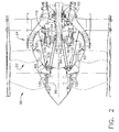
- FIG. 1 is a cross-sectional view of a portion of an exemplary turbine engine assembly 10 having a longitudinal axis 11.
- turbine engine assembly 10 includes a core gas turbine engine 12 generally defined by a frame 13.
- a low-pressure turbine 14 is coupled axially aft of core gas turbine engine 12 and a counter-rotating fan assembly 16 is coupled axially forward of core gas turbine engine 12.
- Core gas turbine engine 12 includes an outer casing 20 that defines an annular core engine inlet 22. Casing 20 surrounds a low-pressure booster compressor 24 to facilitate increasing the pressure of the incoming air to a first pressure level.
- core gas turbine engine 12 is a core CFM56 gas turbine engine available from General Electric Aircraft Engines, Cincinnati, Ohio.
- a high-pressure, multi-stage, axial-flow compressor 26 receives pressurized air from booster compressor 24 and further increases the pressure of the air to a second, higher pressure level.
- the high-pressure air is channeled to a combustor 28 and is mixed with fuel.
- the fuel-air mixture is ignited to raise the temperature and energy level of the pressurized air.
- the high energy combustion products flow to a first or high-pressure turbine 30 for driving compressor 26 through a first rotatable drive shaft 32, and then to second or low-pressure turbine 14 to facilitate driving counter-rotating fan assembly 16 and booster compressor 24 through a second rotatable drive shaft 34 that is coupled coaxially with first drive shaft 32.
- the combustion products leave turbine engine assembly 10 through an exhaust nozzle 36 to provide propulsive jet thrust.
- Counter-rotating fan assembly 16 includes a first or forward fan assembly 50 and a second or an aft fan assembly 52 configured to rotate about longitudinal axis 11.
- the terms "forward fan” and “aft fan” are used herein to indicate that fan assembly 50 is coupled axially upstream from fan assembly 52.
- fan assemblies 50 and 52 are positioned at a forward end of core gas turbine engine 12, as shown in Figures 1-3.
- fan assemblies 50 and 52 are positioned at an aft end of core gas turbine engine 12.
- Fan assemblies 50 and 52 each includes at least one row of rotor blades 60 and 62, respectively, and are positioned within a nacelle 64. Rotor blades 60 are coupled to rotor disk 66 and rotor blades 62 are coupled to rotor disk 68.
- booster compressor 24 includes a plurality of rows of rotor blades 70 that are coupled to a respective rotor disk 72.
- Booster compressor 24 is positioned aft of an inlet guide vane assembly 74 and is coupled to aft fan assembly 52 such that booster compressor 24 rotates at a rotational speed that is substantially equal to a rotational speed of aft fan assembly 52.
- booster compressor 24 is shown as having only three rows of rotor blades 70, booster compressor 24 may have any suitable number and/or rows of rotor blades 70, such as a single row of rotor blades 70 or a plurality of rows of rotor blades 70 that are interdigitated with a plurality of rows of guide vanes 76.
- inlet guide vanes 76 are fixedly or securely coupled to a booster case 78.
- rotor blades 70 are rotatably coupled to rotor disk 72 such that inlet guide vanes 76 are movable during engine operation to facilitate varying a quantity of air channeled through booster compressor 24.
- turbine engine assembly 10 does not include booster compressor 24.
- low-pressure turbine 14 is coupled to forward fan assembly 50 through shaft 34 such that forward fan assembly 50 rotates in a first rotational direction 80.
- Aft fan assembly 52 is coupled to drive shaft 34 and/or low-pressure turbine 14 such that aft fan assembly 52 rotates in an opposite second rotational direction 82.
- FIG. 2 is a schematic diagram of a portion of counter-rotating fan assembly 16 shown in Figure 1.
- first fan assembly 50 includes a cone 84 positioned about longitudinal axis 11.
- Cone 84 is connected at a first or forward end 86 to rotor disk 66 and at a second or aft end 88 to drive shaft 34, as shown in Figure 2.
- Second fan assembly 52 includes a cone 90 positioned coaxially about at least a portion of cone 84 along longitudinal axis 11.
- Cone 90 is coupled at a first or forward end 92 to rotor disk 68 and at a second or aft end 94 to an output of a gearbox 100 and/or to aft end 88 of cone 84 via a rolling bearing assembly, as described in greater detailed below.
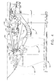
- FIG 3 is a schematic diagram of a portion of the counter-rotating fan assembly 16 shown in Figure 2.
- counter-rotating fan assembly 16 also includes a gearbox 100 that is coupled between aft fan assembly 52 and drive shaft 34 to facilitate rotating aft fan assembly 52 in opposite rotational direction 82 with respect to rotational direction 80 in which forward fan assembly 50 rotates.
- Gearbox 100 has a generally toroidal shape and is configured to be positioned circumferentially about drive shaft 34 to extend substantially about drive shaft 34.
- gearbox 100 includes a support structure 102, at least one gear 103 coupled within support structure 102, an input 104 and an output 106.
- gearbox 100 has a gear ratio of approximately 2.0 to 1 such that forward fan assembly 50 rotates at a rotational speed that is approximately twice the rotational speed of aft fan assembly 52.
- forward fan assembly 50 rotates with a rotational speed that is between approximately 0.67 and approximately 2.1 times faster than the rotational speed of aft fan assembly 52.
- forward fan assembly 50 may rotate at a rotational speed greater than, equal to or less than the rotational speed of aft fan assembly 52.
- a first bearing assembly such as thrust bearing assembly 110 as shown in Figures 1-3, is positioned about drive shaft 34 and/or longitudinal axis 11. Thrust bearing assembly 110 operatively couples and/or is mounted between drive shaft 34 and frame 13 of core gas turbine engine 12.
- thrust bearing assembly 110 includes a radially positioned inner race 111 that is mounted with respect to drive shaft 34. As shown in Figure 3, inner race 111 is mounted to a drive shaft extension 112 operatively coupled to drive shaft 34 so that inner race 111 is rotatable about longitudinal axis 11 with drive shaft 34. In one particular embodiment, drive shaft extension 112 is splined to drive shaft 34. Inner race 111 has a surface 113 defining an inner groove 114 of thrust bearing assembly 110. Surface 113 defining inner groove 114 has a generally arcuate profile.
- Thrust bearing assembly 110 includes a radially positioned outer race 116 securely coupled to frame 13.
- outer race 116 and/or frame 13 acts as a ground for the transfer of thrust loads and/or forces developed or generated by counter-rotating fan assembly 16 and/or booster compressor 24, as discussed in greater detail below.
- Outer race 116 has a surface 117, generally opposing surface 113, which forms an outer groove 118 of thrust bearing assembly 110.
- Surface 117 defining outer groove 118 has a generally arcuate profile.
- At least one roller element, such as a plurality of bearings 119 is movably positioned between inner race 111 and outer race 116. Each bearing 119 is in rolling contact with inner groove 114 and outer groove 118 to allow drive shaft 34 to rotate freely with respect to gearbox 100.
- a second bearing assembly such as thrust bearing assembly 120
- thrust bearing assembly 120 operatively couples and/or is mounted between a forward end portion of first fan assembly 50, such as at or near forward end 86 of cone 84, and a forward end portion of second fan assembly 52, such as at or near forward end 92 of cone 90.
- thrust bearing assembly 120 includes a radially positioned inner race 122 that is mounted with respect to an outer surface of cone 84.
- inner race 122 is mounted to cone 84 so that inner race 122 is rotatable about longitudinal axis 11 with first fan assembly 50.
- Inner race 122 has a surface 123 defining an inner groove 124 of thrust bearing assembly 110.
- Surface 123 defining inner groove 124 has a generally arcuate profile.
- Thrust bearing assembly 120 includes a radially positioned outer race 126 that is mounted with respect to an inner surface of cone 90. As shown in Figure 4, inner race 122 is mounted to cone 90 so that outer race 126 is rotatable about longitudinal axis 11 with second fan assembly 52. Outer race 126 has a surface 127, generally opposing surface 123, which forms an outer groove 128 of thrust bearing assembly 120. Surface 127 defining outer groove 128 has a generally arcuate profile. At least one roller element, such as a plurality of bearings 129, is movably positioned between inner race 122 and outer race 126. Each bearing 129 is in rolling contact with inner groove 124 and outer groove 128 to facilitate relative rotational movement of first fan assembly 50 and/or second fan assembly 52.
- thrust bearing assemblies 110 and/or 120 facilitate maintaining forward fan assembly 50 and/or aft fan assembly 52 in a relatively fixed axial position.
- thrust loads and/or forces generated by first fan assembly 50 are transferred directly from first fan assembly 50 to first thrust bearing assembly 110.
- thrust loads and/or forces generated by second fan assembly 52 and/or booster compressor 24 during operation are transferred from second fan assembly 52 and/or booster compressor 24 to second thrust bearing assembly 120 and from second thrust bearing assembly 120 through drive shaft 34 to first thrust bearing assembly 110.
- the transfer of thrust loads and/or forces through gearbox 100, operatively coupled to second fan assembly 52 is prevented or limited.
- any suitable bearing assembly known to those skilled in the art and guided by the teachings herein provided can be used for or in addition to bearing assembly 110 and/or bearing assembly 120.
- a bearing assembly such as roller bearing assembly 130
- roller bearing assembly 130 is positioned about the outer surface of cone 90 at or near forward end 92, as shown in Figure 4.
- Roller bearing assembly 130 is connected between frame 13 and forward end 92.
- roller bearing assembly 130 acts as a differential bearing assembly in combination with thrust bearing assembly 120 to support second fan assembly 52 and/or transfer thrust loads and/or forces from second fan assembly 52 to frame 13.
- roller bearing assembly 130 includes an inner race 132 that is mounted with respect to cone 90, as shown in Figure 4.
- Inner race 132 is mounted to forward end 92 of cone 90 so that inner race 132 is rotatable about longitudinal axis 11 with second fan assembly 52.
- Inner race 132 has a surface 133 defining an inner groove 134 of roller bearing assembly 130.
- Roller bearing assembly 130 includes an outer race 136 that is securely coupled to frame 13.
- outer race 136 is securely coupled with respect to structural support member 15 and/or frame 13.
- Structural support member 15 and/or frame 13 acts as a ground for the transfer of thrust loads and/or forces developed or generated by counter-rotating fan assembly 16 and/or booster compressor 24.
- Outer race 136 has a surface 137, generally opposing surface 133, which forms an outer groove 138 of roller bearing assembly 130.
- At least one roller element, such as a plurality of rollers 139 is movably positioned between inner race 132 and outer race 136. Each roller 139 is in rolling contact with inner groove 134 and outer groove 138.
- a bearing assembly such as roller bearing assembly 140, is positioned about the outer surface of cone 84 at or near aft end 88, as shown in Figure 3.
- Roller bearing assembly 140 is connected between cone 84 and cone 90.
- Roller bearing assembly 140 includes an inner race 142 that is mounted with respect to aft end 88, as shown in Figure 2.
- Inner race 142 is mounted to cone 84 so that inner race 142 is rotatable about longitudinal axis 11 with first fan assembly 50.
- Inner race 142 has a surface 143 defining an inner groove 144 of roller bearing assembly 140.
- Roller bearing assembly 140 includes an outer race 146 that is mounted with respect to aft end 94 of cone 90, as shown in Figure 3. Outer race 146 is mounted to cone 90 so that outer race 146 is rotatable about longitudinal axis 11 with second fan assembly 52. Outer race 146 has a surface 147, generally opposing surface 143, which forms an outer groove 148 of roller bearing assembly 140. At least one roller element, such as a plurality of rollers 149, is movably positioned between inner race 142 and outer race 146. Each roller 149 is in rolling contact with inner groove 144 and outer groove 148 to facilitate relative rotational movement of cone 84 and/or cone 90.
- roller bearing assemblies 130 and 140 facilitate providing rotational support to aft fan assembly 52 such that aft fan assembly 52 can rotate freely with respect to forward fan assembly 50. Accordingly, roller bearing assemblies 130 and 140 facilitate maintaining aft fan assembly 52 in a relatively fixed radial position within counter-rotating fan assembly 16.
- any suitable bearing assembly known to those skilled in the art and guided by the teachings herein provided can be used for or in addition to bearing assembly 130 and/or bearing assembly 140.
- gearbox 100 is connected to a fixed or stationary component of gas turbine engine 10, such as frame 13 of core turbine engine 12, as shown in Figure 3.
- Gearbox input 104 is rotatably coupled to second drive shaft 34 through drive shaft extension 112 that is splined to drive shaft 34.
- Gearbox output 106 is rotatably coupled to aft fan assembly 52 through an output structure 160.
- a first end of output structure 160 is splined to gearbox output 106 and a second end of output structure 160 is coupled to aft fan forward shaft 168 to facilitate driving aft fan assembly 52.
- gas turbine engine assembly 10 includes a spline system 200 for mounting gearbox 100 to counter-rotating fan assembly 16.
- Gearbox 100 is fixedly or securely coupled to frame 13 of core gas turbine engine 12, for example at gearbox support structure 102.
- Spline system 200 isolates gearbox 100 from first fan assembly 50 and/or second fan assembly 52 to prevent or limit thrust loads and/or forces exerted on gearbox 100 as a result of counter-rotating fan assembly 16 operation.
- First fan assembly 50 is rotatably coupled to input 104 such that first fan assembly 50 rotates in a first direction, as indicated by rotational arrow 80 in Figure 1.
- Second fan assembly 52 is rotatably coupled to output 106 such that second fan assembly 52 rotates in a second direction, as indicated by rotational arrow 82 in Figure 1, opposite the first direction.
- spline system 200 includes a plurality of spline assemblies, such as spline assembly 202, 204, 206 and/or 208.
- a first spline assembly 202 couples input 104 to drive shaft extension 112.
- Drive shaft extension 112 includes a first portion 210 and a second portion 212, as shown in Figure 3.
- First spline assembly 202 couples input 104 to first portion 10 and a second spline assembly 204, the same or similar to first spline assembly 202, couples first portion 210 to second portion 212 to rotatably couple input 104 to drive shaft 34.
- second spline assembly 204 facilitates movement of thrust bearing assembly 110 with respect to gearbox 100 in the axial direction, i.e., along or parallel with longitudinal axis 11 of turbine engine assembly 10.
- spline assembly 204 includes a member forming a plurality of splines positioned about a periphery of the member.
- the member connected to second portion 212 of drive shaft extension 112, is positionable within a cavity formed in a cooperating housing, connected to first portion 210, such that the plurality of splines mesh or interfere with slots formed on an inner periphery of the housing to transfer torsional loads and/or forces from second portion 212 to first portion 210 of drive shaft extension 112.
- the member is positioned within the cooperating housing to facilitate movement of the member within the housing in an axial direction, e.g., along or parallel with longitudinal axis 11, which facilitates axial movement of second portion 212 with respect to first portion 210.
- each spline assembly 204, 206 and 208 are the same or similar, as described above with reference to spline assembly 204.
- a third spline assembly 206 slidably couples output 106 to output structure 160.
- Third spline assembly 206 facilitates axial movement of aft fan forward shaft 168 with respect to gearbox 100.
- a fourth spline assembly 208 slidably couples second portion 212 of drive shaft extension 112 to drive shaft 34.
- spline assemblies 202, 204, 206 and/or 208 pass only torsional or torque loads and/or forces to gearbox 100 such that gearbox 100 remains in a substantially fixed position with respect to the frame of low-pressure turbine 14.
- first portion 210 includes a radially inner portion 230 that is coupled to input 104 through spline assembly 202 and a radially outer portion 232 that is coupled to second portion 212 through spline assembly 204.
- First portion 210 has a first thickness at or near inner portion 230 and a second thickness at or near outer portion 232, which is less than first thickness.
- a thickness of first portion 210 gradually decreases from radially inner portion 230 to radially outer portion 232. The second thickness is selected such that first portion 230 will separate from second portion 232, i.e.
- first portion 210 will break, when first portion 210 is subjected to a determined torsional load and/or force.
- relatively large radial loads and/or forces may be applied to aft fan assembly 52.
- first portion 210 breaks such that forward fan assembly 50 continues to operate as aft fan assembly 52 freewheels.
- gearbox 100 is located within a sump 170 at least partially defined between output structure 160 and structural support member 15 configured to support aft fan assembly 52. During operation, gearbox 100 is at least partially submerged within lubrication fluid contained in sump 170 to continuously lubricate gearbox 100 during engine operation.
- the gas turbine engine assembly described herein includes a counter-rotating fan assembly having a geared single rotation low-pressure turbine.
- the assembly facilitates reducing at least some of the complexities associated with known counter-rotating low-pressure turbines. More specifically, the gas turbine engine assembly described herein includes a front fan that is rotatably coupled to a single rotation low-pressure turbine, and an aft fan and booster assembly that are rotatably coupled together, and driven by, the low-pressure turbine via a gearbox. Moreover, the aft fan assembly and booster assembly are driven at the same speed, which, in one embodiment, is approximately one-half the front fan speed.
- gas turbine engine assembly described herein is configured such that approximately 40% of power generated by the low-pressure turbine is transmitted through the gearbox to the aft fan assembly to facilitate reducing gear losses. Therefore, in the event of a gearbox failure, the aft fan assembly will cease to rotate. However, the front fan assembly will continue to rotate because the front fan assembly is directly driven by the low-pressure turbine.
- a spline system of the present invention facilitates preventing or limiting axial loads developed as a result of thrust loads and/or forces generated by the counter-rotating fan assembly and/or the coupled booster compressor to be transferred to the gearbox.
- the spline system includes spline assemblies that couple the gearbox to the drive shaft and/or components of the counter-rotating fan assembly. The spline assemblies transfer torsional loads and/or forces to the gearbox but prevent or limit axial loads and/or forces from being transferred to the gearbox.
- the gearbox remains substantially fixed with respect to the gas turbine engine assembly frame. As a result, the gearbox is only subjected to torsional loads and/or forces.
- Exemplary embodiments of a gas turbine engine assembly and methods of assembly the gas turbine engine assembly are described above in detail.
- the assembly and method are not limited to the specific embodiments described herein, but rather, components of the assembly and/or steps of the method may be utilized independently and separately from other components and/or steps described herein. Further, the described assembly components and/or the method steps can also be defined in, or used in combination with, other assemblies and/or methods, and are not limited to practice with only the assembly and/or method as described herein.
- turbine engine assembly 11 longitudinal axis 12 core gas turbine engine 13 frame 14 low-pressure turbine 15 structural support member 16 rotating fan assembly 20 outer casing 22 engine inlet 24 booster compressor 26 compressor 28 combustor 30 high-pressure turbine 32 first rotatable drive shaft 34 second rotatable drive shaft 36 exhaust nozzle 50 fan assemblies 52 aft fan assembly 60 rotor blades 62 rotor blades 64 nacelle 66 rotor disk 68 rotor disk 70 rotor blades 72 rotor disk 74 inlet guide vane assembly 76 inlet guide vanes 78 booster case 80 first rotational direction 82 second rotational direction 84 cone 86 first or forward end 88 second or aft end 90 cone 92 first or forward end 94 second or aft end 100 gearbox 102 housing 103 gear 104 input 106 output 110 thrust bearing assembly 111 inner race 112 bearing support structure 113 surface 114 inner groove 116 outer race 117 surface 118 outer groove 119 plurality of bearings 120 thrust bearing assembly 122 inner race 123 surface 124 inner groove
Landscapes
- Engineering & Computer Science (AREA)
- General Engineering & Computer Science (AREA)
- Mechanical Engineering (AREA)
- Chemical & Material Sciences (AREA)
- Combustion & Propulsion (AREA)
- Structures Of Non-Positive Displacement Pumps (AREA)
- Turbine Rotor Nozzle Sealing (AREA)
Applications Claiming Priority (1)
| Application Number | Priority Date | Filing Date | Title |
|---|---|---|---|
| US11/254,018 US7493754B2 (en) | 2005-10-19 | 2005-10-19 | Gas turbine engine assembly and methods of assembling same |
Publications (2)
| Publication Number | Publication Date |
|---|---|
| EP1777380A2 true EP1777380A2 (de) | 2007-04-25 |
| EP1777380A3 EP1777380A3 (de) | 2014-04-09 |
Family
ID=37192960
Family Applications (1)
| Application Number | Title | Priority Date | Filing Date |
|---|---|---|---|
| EP06255265.8A Withdrawn EP1777380A3 (de) | 2005-10-19 | 2006-10-12 | Gasturbinentriebwerksanordnung und entsprechendes Montageverfahren |
Country Status (4)
| Country | Link |
|---|---|
| US (1) | US7493754B2 (de) |
| EP (1) | EP1777380A3 (de) |
| JP (1) | JP5111824B2 (de) |
| CN (1) | CN1952368B (de) |
Cited By (5)
| Publication number | Priority date | Publication date | Assignee | Title |
|---|---|---|---|---|
| WO2014158439A1 (en) * | 2013-03-12 | 2014-10-02 | United Technologies Corporation | Flexible coupling for geared turbine engine |
| EP3144486A1 (de) * | 2015-09-18 | 2017-03-22 | Rolls-Royce plc | Wellenanordnung für einen gasturbinenmotor |
| EP3144487A1 (de) * | 2015-09-18 | 2017-03-22 | Rolls-Royce plc | Kopplung für einen getriebefan |
| US10119465B2 (en) | 2015-06-23 | 2018-11-06 | United Technologies Corporation | Geared turbofan with independent flexible ring gears and oil collectors |
| US11542989B2 (en) | 2017-11-30 | 2023-01-03 | Rolls-Royce Deutschland Ltd & Co Kg | Coupling device for rotably coupling a shaft with a gearbox in a geared turbo fan engine |
Families Citing this family (59)
| Publication number | Priority date | Publication date | Assignee | Title |
|---|---|---|---|---|
| US7526913B2 (en) * | 2005-10-19 | 2009-05-05 | General Electric Company | Gas turbine engine assembly and methods of assembling same |
| US7493753B2 (en) * | 2005-10-19 | 2009-02-24 | General Electric Company | Gas turbine engine assembly and methods of assembling same |
| US7513103B2 (en) * | 2005-10-19 | 2009-04-07 | General Electric Company | Gas turbine engine assembly and methods of assembling same |
| US7726113B2 (en) * | 2005-10-19 | 2010-06-01 | General Electric Company | Gas turbine engine assembly and methods of assembling same |
| US7490461B2 (en) * | 2005-10-19 | 2009-02-17 | General Electric Company | Gas turbine engine assembly and methods of assembling same |
| US7685808B2 (en) * | 2005-10-19 | 2010-03-30 | General Electric Company | Gas turbine engine assembly and methods of assembling same |
| US7603844B2 (en) * | 2005-10-19 | 2009-10-20 | General Electric Company | Gas turbine engine assembly and methods of assembling same |
| US7661260B2 (en) * | 2006-09-27 | 2010-02-16 | General Electric Company | Gas turbine engine assembly and method of assembling same |
| US7832193B2 (en) * | 2006-10-27 | 2010-11-16 | General Electric Company | Gas turbine engine assembly and methods of assembling same |
| US7716914B2 (en) * | 2006-12-21 | 2010-05-18 | General Electric Company | Turbofan engine assembly and method of assembling same |
| US10151248B2 (en) | 2007-10-03 | 2018-12-11 | United Technologies Corporation | Dual fan gas turbine engine and gear train |
| US8205432B2 (en) * | 2007-10-03 | 2012-06-26 | United Technologies Corporation | Epicyclic gear train for turbo fan engine |
| US8534074B2 (en) * | 2008-05-13 | 2013-09-17 | Rolls-Royce Corporation | Dual clutch arrangement and method |
| US20100005810A1 (en) * | 2008-07-11 | 2010-01-14 | Rob Jarrell | Power transmission among shafts in a turbine engine |
| US8480527B2 (en) * | 2008-08-27 | 2013-07-09 | Rolls-Royce Corporation | Gearing arrangement |
| US8166748B2 (en) * | 2008-11-21 | 2012-05-01 | General Electric Company | Gas turbine engine booster having rotatable radially inwardly extending blades and non-rotatable vanes |
| US8075438B2 (en) * | 2008-12-11 | 2011-12-13 | Rolls-Royce Corporation | Apparatus and method for transmitting a rotary input into counter-rotating outputs |
| US8021267B2 (en) * | 2008-12-11 | 2011-09-20 | Rolls-Royce Corporation | Coupling assembly |
| US8360714B2 (en) | 2011-04-15 | 2013-01-29 | United Technologies Corporation | Gas turbine engine front center body architecture |
| US9896966B2 (en) | 2011-08-29 | 2018-02-20 | United Technologies Corporation | Tie rod for a gas turbine engine |
| CN102330605B (zh) * | 2011-09-05 | 2013-06-26 | 沈阳黎明航空发动机(集团)有限责任公司 | 一种转子与前后支承组合装配的重型燃机装配方法 |
| CA2789325C (en) * | 2011-10-27 | 2015-04-07 | United Technologies Corporation | Gas turbine engine front center body architecture |
| US10400629B2 (en) | 2012-01-31 | 2019-09-03 | United Technologies Corporation | Gas turbine engine shaft bearing configuration |
| US8863491B2 (en) | 2012-01-31 | 2014-10-21 | United Technologies Corporation | Gas turbine engine shaft bearing configuration |
| US9011076B2 (en) | 2012-02-29 | 2015-04-21 | United Technologies Corporation | Counter-rotating low pressure turbine with gear system mounted to turbine exhaust case |
| US9022725B2 (en) | 2012-02-29 | 2015-05-05 | United Technologies Corporation | Counter-rotating low pressure turbine with gear system mounted to turbine exhaust case |
| US9194290B2 (en) | 2012-02-29 | 2015-11-24 | United Technologies Corporation | Counter-rotating low pressure turbine without turbine exhaust case |
| US8956108B2 (en) * | 2012-05-11 | 2015-02-17 | Pratt & Whitney Canada Corp | Geared fan assembly |
| WO2014137571A1 (en) | 2013-03-04 | 2014-09-12 | United Technologies Corporation | Fan drive gear system spline oil lubrication scheme |
| US9752500B2 (en) * | 2013-03-14 | 2017-09-05 | Pratt & Whitney Canada Corp. | Gas turbine engine with transmission and method of adjusting rotational speed |
| US10000293B2 (en) | 2015-01-23 | 2018-06-19 | General Electric Company | Gas-electric propulsion system for an aircraft |
| JP6540167B2 (ja) | 2015-04-02 | 2019-07-10 | 株式会社Ihi | スプライン接続構造及びスプラインシャフト |
| US9884687B2 (en) | 2015-09-21 | 2018-02-06 | General Electric Company | Non-axis symmetric aft engine |
| US9637217B2 (en) | 2015-09-21 | 2017-05-02 | General Electric Company | Aircraft having an aft engine |
| US9821917B2 (en) | 2015-09-21 | 2017-11-21 | General Electric Company | Aft engine for an aircraft |
| US9815560B2 (en) * | 2015-09-21 | 2017-11-14 | General Electric Company | AFT engine nacelle shape for an aircraft |
| US9957055B2 (en) | 2015-09-21 | 2018-05-01 | General Electric Company | Aft engine for an aircraft |
| US10017270B2 (en) | 2015-10-09 | 2018-07-10 | General Electric Company | Aft engine for an aircraft |
| US9764848B1 (en) | 2016-03-07 | 2017-09-19 | General Electric Company | Propulsion system for an aircraft |
| US10392119B2 (en) | 2016-04-11 | 2019-08-27 | General Electric Company | Electric propulsion engine for an aircraft |
| US10252810B2 (en) | 2016-04-19 | 2019-04-09 | General Electric Company | Propulsion engine for an aircraft |
| US10392120B2 (en) | 2016-04-19 | 2019-08-27 | General Electric Company | Propulsion engine for an aircraft |
| US10800539B2 (en) * | 2016-08-19 | 2020-10-13 | General Electric Company | Propulsion engine for an aircraft |
| US10676205B2 (en) | 2016-08-19 | 2020-06-09 | General Electric Company | Propulsion engine for an aircraft |
| US11105340B2 (en) | 2016-08-19 | 2021-08-31 | General Electric Company | Thermal management system for an electric propulsion engine |
| US10093428B2 (en) | 2016-08-22 | 2018-10-09 | General Electric Company | Electric propulsion system |
| US10071811B2 (en) | 2016-08-22 | 2018-09-11 | General Electric Company | Embedded electric machine |
| US10487839B2 (en) | 2016-08-22 | 2019-11-26 | General Electric Company | Embedded electric machine |
| US10308366B2 (en) | 2016-08-22 | 2019-06-04 | General Electric Company | Embedded electric machine |
| US10822103B2 (en) | 2017-02-10 | 2020-11-03 | General Electric Company | Propulsor assembly for an aircraft |
| US11149578B2 (en) | 2017-02-10 | 2021-10-19 | General Electric Company | Propulsion system for an aircraft |
| US10793281B2 (en) | 2017-02-10 | 2020-10-06 | General Electric Company | Propulsion system for an aircraft |
| US10137981B2 (en) | 2017-03-31 | 2018-11-27 | General Electric Company | Electric propulsion system for an aircraft |
| US10762726B2 (en) | 2017-06-13 | 2020-09-01 | General Electric Company | Hybrid-electric propulsion system for an aircraft |
| US11156128B2 (en) | 2018-08-22 | 2021-10-26 | General Electric Company | Embedded electric machine |
| US11142330B2 (en) * | 2018-08-30 | 2021-10-12 | Aurora Flight Sciences Corporation | Mechanically-distributed propulsion drivetrain and architecture |
| US11097849B2 (en) | 2018-09-10 | 2021-08-24 | General Electric Company | Aircraft having an aft engine |
| EP4166762A3 (de) * | 2021-10-15 | 2023-08-09 | Raytheon Technologies Corporation | Radial-aussenlagerträger für eine rotierende struktur eines turbinenmotors |
| CN115056170B (zh) * | 2022-06-07 | 2023-06-23 | 中国航发航空科技股份有限公司 | 发动机涡轮叶片整体装配用弓型夹 |
Citations (5)
| Publication number | Priority date | Publication date | Assignee | Title |
|---|---|---|---|---|
| GB878934A (en) * | 1959-08-13 | 1961-10-04 | Rolls Royce | Improvements in gas turbine jet propulsion engines |
| US3922852A (en) * | 1973-10-17 | 1975-12-02 | Gen Electric | Variable pitch fan for gas turbine engine |
| US6158210A (en) * | 1998-12-03 | 2000-12-12 | General Electric Company | Gear driven booster |
| US6223616B1 (en) * | 1999-12-22 | 2001-05-01 | United Technologies Corporation | Star gear system with lubrication circuit and lubrication method therefor |
| US6381948B1 (en) * | 1998-06-26 | 2002-05-07 | Mtu Aero Engines Gmbh | Driving mechanism with counter-rotating rotors |
Family Cites Families (28)
| Publication number | Priority date | Publication date | Assignee | Title |
|---|---|---|---|---|
| US3866415A (en) * | 1974-02-25 | 1975-02-18 | Gen Electric | Fan blade actuator using pressurized air |
| GB2195712B (en) * | 1986-10-08 | 1990-08-29 | Rolls Royce Plc | A turbofan gas turbine engine |
| DE3714990A1 (de) * | 1987-05-06 | 1988-12-01 | Mtu Muenchen Gmbh | Propfan-turbotriebwerk |
| DE3738703A1 (de) * | 1987-05-27 | 1988-12-08 | Mtu Muenchen Gmbh | Kombiniertes, umschaltbares strahltriebwerk zum antrieb von flugzeugen und raumfahrzeugen |
| US4744214A (en) * | 1987-06-29 | 1988-05-17 | United Technologies Corporation | Engine modularity |
| DE3812027A1 (de) * | 1988-04-11 | 1989-10-26 | Mtu Muenchen Gmbh | Propfan-turbotriebwerk |
| US5010729A (en) * | 1989-01-03 | 1991-04-30 | General Electric Company | Geared counterrotating turbine/fan propulsion system |
| US4969325A (en) * | 1989-01-03 | 1990-11-13 | General Electric Company | Turbofan engine having a counterrotating partially geared fan drive turbine |
| US5394967A (en) * | 1993-02-12 | 1995-03-07 | Warn Industries, Inc. | Connect/disconnect mechanism for a vehicle drive train |
| US5809772A (en) | 1996-03-29 | 1998-09-22 | General Electric Company | Turbofan engine with a core driven supercharged bypass duct |
| US5806303A (en) | 1996-03-29 | 1998-09-15 | General Electric Company | Turbofan engine with a core driven supercharged bypass duct and fixed geometry nozzle |
| US5867980A (en) | 1996-12-17 | 1999-02-09 | General Electric Company | Turbofan engine with a low pressure turbine driven supercharger in a bypass duct operated by a fuel rich combustor and an afterburner |
| US5813214A (en) | 1997-01-03 | 1998-09-29 | General Electric Company | Bearing lubrication configuration in a turbine engine |
| US6732502B2 (en) | 2002-03-01 | 2004-05-11 | General Electric Company | Counter rotating aircraft gas turbine engine with high overall pressure ratio compressor |
| US6619030B1 (en) | 2002-03-01 | 2003-09-16 | General Electric Company | Aircraft engine with inter-turbine engine frame supported counter rotating low pressure turbine rotors |
| US6739120B2 (en) | 2002-04-29 | 2004-05-25 | General Electric Company | Counterrotatable booster compressor assembly for a gas turbine engine |
| US6684626B1 (en) | 2002-07-30 | 2004-02-03 | General Electric Company | Aircraft gas turbine engine with control vanes for counter rotating low pressure turbines |
| US6711887B2 (en) | 2002-08-19 | 2004-03-30 | General Electric Co. | Aircraft gas turbine engine with tandem non-interdigitated counter rotating low pressure turbines |
| US6763652B2 (en) | 2002-09-24 | 2004-07-20 | General Electric Company | Variable torque split aircraft gas turbine engine counter rotating low pressure turbines |
| US6763653B2 (en) | 2002-09-24 | 2004-07-20 | General Electric Company | Counter rotating fan aircraft gas turbine engine with aft booster |
| US6763654B2 (en) | 2002-09-30 | 2004-07-20 | General Electric Co. | Aircraft gas turbine engine having variable torque split counter rotating low pressure turbines and booster aft of counter rotating fans |
| US7603844B2 (en) * | 2005-10-19 | 2009-10-20 | General Electric Company | Gas turbine engine assembly and methods of assembling same |
| US7685808B2 (en) * | 2005-10-19 | 2010-03-30 | General Electric Company | Gas turbine engine assembly and methods of assembling same |
| US7493753B2 (en) * | 2005-10-19 | 2009-02-24 | General Electric Company | Gas turbine engine assembly and methods of assembling same |
| US7490461B2 (en) * | 2005-10-19 | 2009-02-17 | General Electric Company | Gas turbine engine assembly and methods of assembling same |
| US7490460B2 (en) * | 2005-10-19 | 2009-02-17 | General Electric Company | Gas turbine engine assembly and methods of assembling same |
| US7841165B2 (en) * | 2006-10-31 | 2010-11-30 | General Electric Company | Gas turbine engine assembly and methods of assembling same |
| US7716914B2 (en) * | 2006-12-21 | 2010-05-18 | General Electric Company | Turbofan engine assembly and method of assembling same |
-
2005
- 2005-10-19 US US11/254,018 patent/US7493754B2/en not_active Expired - Fee Related
-
2006
- 2006-10-12 EP EP06255265.8A patent/EP1777380A3/de not_active Withdrawn
- 2006-10-13 JP JP2006279806A patent/JP5111824B2/ja not_active Expired - Fee Related
- 2006-10-19 CN CN2006101355618A patent/CN1952368B/zh not_active Expired - Fee Related
Patent Citations (5)
| Publication number | Priority date | Publication date | Assignee | Title |
|---|---|---|---|---|
| GB878934A (en) * | 1959-08-13 | 1961-10-04 | Rolls Royce | Improvements in gas turbine jet propulsion engines |
| US3922852A (en) * | 1973-10-17 | 1975-12-02 | Gen Electric | Variable pitch fan for gas turbine engine |
| US6381948B1 (en) * | 1998-06-26 | 2002-05-07 | Mtu Aero Engines Gmbh | Driving mechanism with counter-rotating rotors |
| US6158210A (en) * | 1998-12-03 | 2000-12-12 | General Electric Company | Gear driven booster |
| US6223616B1 (en) * | 1999-12-22 | 2001-05-01 | United Technologies Corporation | Star gear system with lubrication circuit and lubrication method therefor |
Cited By (13)
| Publication number | Priority date | Publication date | Assignee | Title |
|---|---|---|---|---|
| US10787970B2 (en) | 2013-03-12 | 2020-09-29 | Raytheon Technologies Corporation | Flexible coupling for geared turbine engine |
| US9863326B2 (en) | 2013-03-12 | 2018-01-09 | United Technologies Corporation | Flexible coupling for geared turbine engine |
| US10087851B2 (en) | 2013-03-12 | 2018-10-02 | United Technologies Corporation | Flexible coupling for geared turbine engine |
| US10087850B2 (en) | 2013-03-12 | 2018-10-02 | United Technologies Corporation | Flexible coupling for geared turbine engine |
| US10787971B2 (en) | 2013-03-12 | 2020-09-29 | Raytheon Technologies Corporation | Flexible coupling for geared turbine engine |
| WO2014158439A1 (en) * | 2013-03-12 | 2014-10-02 | United Technologies Corporation | Flexible coupling for geared turbine engine |
| US11136920B2 (en) | 2013-03-12 | 2021-10-05 | Raytheon Technologies Corporation | Flexible coupling for geared turbine engine |
| US11536203B2 (en) | 2013-03-12 | 2022-12-27 | Raytheon Technologies Corporation | Flexible coupling for geared turbine engine |
| US10119465B2 (en) | 2015-06-23 | 2018-11-06 | United Technologies Corporation | Geared turbofan with independent flexible ring gears and oil collectors |
| EP3144486A1 (de) * | 2015-09-18 | 2017-03-22 | Rolls-Royce plc | Wellenanordnung für einen gasturbinenmotor |
| EP3144487A1 (de) * | 2015-09-18 | 2017-03-22 | Rolls-Royce plc | Kopplung für einen getriebefan |
| US10393068B2 (en) | 2015-09-18 | 2019-08-27 | Rolls-Royce Plc | Shafting arrangement for a gas turbine engine |
| US11542989B2 (en) | 2017-11-30 | 2023-01-03 | Rolls-Royce Deutschland Ltd & Co Kg | Coupling device for rotably coupling a shaft with a gearbox in a geared turbo fan engine |
Also Published As
| Publication number | Publication date |
|---|---|
| CN1952368A (zh) | 2007-04-25 |
| JP2007113578A (ja) | 2007-05-10 |
| JP5111824B2 (ja) | 2013-01-09 |
| CN1952368B (zh) | 2010-12-22 |
| EP1777380A3 (de) | 2014-04-09 |
| US20070084190A1 (en) | 2007-04-19 |
| US7493754B2 (en) | 2009-02-24 |
Similar Documents
| Publication | Publication Date | Title |
|---|---|---|
| US7493754B2 (en) | Gas turbine engine assembly and methods of assembling same | |
| US7490461B2 (en) | Gas turbine engine assembly and methods of assembling same | |
| US7513103B2 (en) | Gas turbine engine assembly and methods of assembling same | |
| EP1777406B1 (de) | Turbofan-Triebwerk mit gegenläufigen Fans | |
| US7493753B2 (en) | Gas turbine engine assembly and methods of assembling same | |
| US7685808B2 (en) | Gas turbine engine assembly and methods of assembling same | |
| US7526913B2 (en) | Gas turbine engine assembly and methods of assembling same | |
| US7603844B2 (en) | Gas turbine engine assembly and methods of assembling same | |
| CA2606736C (en) | Gas turbine engine assembly and methods of assembling same | |
| US7832193B2 (en) | Gas turbine engine assembly and methods of assembling same | |
| EP1783344B1 (de) | Gasturbinentriebwerksanordnung und Verfahren zu deren Zusammenbau | |
| US7726113B2 (en) | Gas turbine engine assembly and methods of assembling same | |
| US7694505B2 (en) | Gas turbine engine assembly and method of assembling same |
Legal Events
| Date | Code | Title | Description |
|---|---|---|---|
| PUAI | Public reference made under article 153(3) epc to a published international application that has entered the european phase |
Free format text: ORIGINAL CODE: 0009012 |
|
| AK | Designated contracting states |
Kind code of ref document: A2 Designated state(s): AT BE BG CH CY CZ DE DK EE ES FI FR GB GR HU IE IS IT LI LT LU LV MC NL PL PT RO SE SI SK TR |
|
| AX | Request for extension of the european patent |
Extension state: AL BA HR MK YU |
|
| PUAL | Search report despatched |
Free format text: ORIGINAL CODE: 0009013 |
|
| AK | Designated contracting states |
Kind code of ref document: A3 Designated state(s): AT BE BG CH CY CZ DE DK EE ES FI FR GB GR HU IE IS IT LI LT LU LV MC NL PL PT RO SE SI SK TR |
|
| AX | Request for extension of the european patent |
Extension state: AL BA HR MK RS |
|
| RIC1 | Information provided on ipc code assigned before grant |
Ipc: F01D 25/16 20060101ALI20140303BHEP Ipc: F02C 7/20 20060101ALI20140303BHEP Ipc: F01D 25/28 20060101AFI20140303BHEP Ipc: F02C 3/107 20060101ALI20140303BHEP Ipc: F16D 1/10 20060101ALI20140303BHEP |
|
| 17P | Request for examination filed |
Effective date: 20141009 |
|
| RBV | Designated contracting states (corrected) |
Designated state(s): AT BE BG CH CY CZ DE DK EE ES FI FR GB GR HU IE IS IT LI LT LU LV MC NL PL PT RO SE SI SK TR |
|
| AKX | Designation fees paid |
Designated state(s): DE FR GB |
|
| AXX | Extension fees paid |
Extension state: MK Extension state: HR Extension state: AL Extension state: RS Extension state: BA |
|
| STAA | Information on the status of an ep patent application or granted ep patent |
Free format text: STATUS: THE APPLICATION IS DEEMED TO BE WITHDRAWN |
|
| 18D | Application deemed to be withdrawn |
Effective date: 20160503 |