EP1777380A2 - Gas turbine engine assembly and methods of assembling same - Google Patents
Gas turbine engine assembly and methods of assembling same Download PDFInfo
- Publication number
- EP1777380A2 EP1777380A2 EP06255265A EP06255265A EP1777380A2 EP 1777380 A2 EP1777380 A2 EP 1777380A2 EP 06255265 A EP06255265 A EP 06255265A EP 06255265 A EP06255265 A EP 06255265A EP 1777380 A2 EP1777380 A2 EP 1777380A2
- Authority
- EP
- European Patent Office
- Prior art keywords
- assembly
- fan assembly
- spline
- gearbox
- turbine engine
- Prior art date
- Legal status (The legal status is an assumption and is not a legal conclusion. Google has not performed a legal analysis and makes no representation as to the accuracy of the status listed.)
- Withdrawn
Links
Images


Classifications
-
- F—MECHANICAL ENGINEERING; LIGHTING; HEATING; WEAPONS; BLASTING
- F02—COMBUSTION ENGINES; HOT-GAS OR COMBUSTION-PRODUCT ENGINE PLANTS
- F02K—JET-PROPULSION PLANTS
- F02K3/00—Plants including a gas turbine driving a compressor or a ducted fan
- F02K3/02—Plants including a gas turbine driving a compressor or a ducted fan in which part of the working fluid by-passes the turbine and combustion chamber
- F02K3/04—Plants including a gas turbine driving a compressor or a ducted fan in which part of the working fluid by-passes the turbine and combustion chamber the plant including ducted fans, i.e. fans with high volume, low pressure outputs, for augmenting the jet thrust, e.g. of double-flow type
- F02K3/072—Plants including a gas turbine driving a compressor or a ducted fan in which part of the working fluid by-passes the turbine and combustion chamber the plant including ducted fans, i.e. fans with high volume, low pressure outputs, for augmenting the jet thrust, e.g. of double-flow type with counter-rotating, e.g. fan rotors
-
- F—MECHANICAL ENGINEERING; LIGHTING; HEATING; WEAPONS; BLASTING
- F01—MACHINES OR ENGINES IN GENERAL; ENGINE PLANTS IN GENERAL; STEAM ENGINES
- F01D—NON-POSITIVE DISPLACEMENT MACHINES OR ENGINES, e.g. STEAM TURBINES
- F01D25/00—Component parts, details, or accessories, not provided for in, or of interest apart from, other groups
- F01D25/16—Arrangement of bearings; Supporting or mounting bearings in casings
- F01D25/162—Bearing supports
-
- F—MECHANICAL ENGINEERING; LIGHTING; HEATING; WEAPONS; BLASTING
- F02—COMBUSTION ENGINES; HOT-GAS OR COMBUSTION-PRODUCT ENGINE PLANTS
- F02C—GAS-TURBINE PLANTS; AIR INTAKES FOR JET-PROPULSION PLANTS; CONTROLLING FUEL SUPPLY IN AIR-BREATHING JET-PROPULSION PLANTS
- F02C3/00—Gas-turbine plants characterised by the use of combustion products as the working fluid
- F02C3/04—Gas-turbine plants characterised by the use of combustion products as the working fluid having a turbine driving a compressor
- F02C3/107—Gas-turbine plants characterised by the use of combustion products as the working fluid having a turbine driving a compressor with two or more rotors connected by power transmission
-
- F—MECHANICAL ENGINEERING; LIGHTING; HEATING; WEAPONS; BLASTING
- F02—COMBUSTION ENGINES; HOT-GAS OR COMBUSTION-PRODUCT ENGINE PLANTS
- F02C—GAS-TURBINE PLANTS; AIR INTAKES FOR JET-PROPULSION PLANTS; CONTROLLING FUEL SUPPLY IN AIR-BREATHING JET-PROPULSION PLANTS
- F02C7/00—Features, components parts, details or accessories, not provided for in, or of interest apart form groups F02C1/00 - F02C6/00; Air intakes for jet-propulsion plants
- F02C7/36—Power transmission arrangements between the different shafts of the gas turbine plant, or between the gas-turbine plant and the power user
-
- F—MECHANICAL ENGINEERING; LIGHTING; HEATING; WEAPONS; BLASTING
- F16—ENGINEERING ELEMENTS AND UNITS; GENERAL MEASURES FOR PRODUCING AND MAINTAINING EFFECTIVE FUNCTIONING OF MACHINES OR INSTALLATIONS; THERMAL INSULATION IN GENERAL
- F16D—COUPLINGS FOR TRANSMITTING ROTATION; CLUTCHES; BRAKES
- F16D1/00—Couplings for rigidly connecting two coaxial shafts or other movable machine elements
- F16D1/10—Quick-acting couplings in which the parts are connected by simply bringing them together axially
- F16D1/101—Quick-acting couplings in which the parts are connected by simply bringing them together axially without axial retaining means rotating with the coupling
-
- F—MECHANICAL ENGINEERING; LIGHTING; HEATING; WEAPONS; BLASTING
- F05—INDEXING SCHEMES RELATING TO ENGINES OR PUMPS IN VARIOUS SUBCLASSES OF CLASSES F01-F04
- F05D—INDEXING SCHEME FOR ASPECTS RELATING TO NON-POSITIVE-DISPLACEMENT MACHINES OR ENGINES, GAS-TURBINES OR JET-PROPULSION PLANTS
- F05D2230/00—Manufacture
- F05D2230/60—Assembly methods
- F05D2230/64—Assembly methods using positioning or alignment devices for aligning or centring, e.g. pins
- F05D2230/642—Assembly methods using positioning or alignment devices for aligning or centring, e.g. pins using maintaining alignment while permitting differential dilatation
-
- F—MECHANICAL ENGINEERING; LIGHTING; HEATING; WEAPONS; BLASTING
- F05—INDEXING SCHEMES RELATING TO ENGINES OR PUMPS IN VARIOUS SUBCLASSES OF CLASSES F01-F04
- F05D—INDEXING SCHEME FOR ASPECTS RELATING TO NON-POSITIVE-DISPLACEMENT MACHINES OR ENGINES, GAS-TURBINES OR JET-PROPULSION PLANTS
- F05D2250/00—Geometry
- F05D2250/40—Movement of components
- F05D2250/41—Movement of components with one degree of freedom
-
- F—MECHANICAL ENGINEERING; LIGHTING; HEATING; WEAPONS; BLASTING
- F05—INDEXING SCHEMES RELATING TO ENGINES OR PUMPS IN VARIOUS SUBCLASSES OF CLASSES F01-F04
- F05D—INDEXING SCHEME FOR ASPECTS RELATING TO NON-POSITIVE-DISPLACEMENT MACHINES OR ENGINES, GAS-TURBINES OR JET-PROPULSION PLANTS
- F05D2260/00—Function
- F05D2260/40—Transmission of power
- F05D2260/403—Transmission of power through the shape of the drive components
- F05D2260/4031—Transmission of power through the shape of the drive components as in toothed gearing
- F05D2260/40311—Transmission of power through the shape of the drive components as in toothed gearing of the epicyclical, planetary or differential type
-
- F—MECHANICAL ENGINEERING; LIGHTING; HEATING; WEAPONS; BLASTING
- F16—ENGINEERING ELEMENTS AND UNITS; GENERAL MEASURES FOR PRODUCING AND MAINTAINING EFFECTIVE FUNCTIONING OF MACHINES OR INSTALLATIONS; THERMAL INSULATION IN GENERAL
- F16D—COUPLINGS FOR TRANSMITTING ROTATION; CLUTCHES; BRAKES
- F16D1/00—Couplings for rigidly connecting two coaxial shafts or other movable machine elements
- F16D1/10—Quick-acting couplings in which the parts are connected by simply bringing them together axially
- F16D2001/103—Quick-acting couplings in which the parts are connected by simply bringing them together axially the torque is transmitted via splined connections
Definitions
- This invention relates generally to gas turbine engines, and more specifically to gas turbine engine assemblies and methods of assembling the same.
- At least some known gas turbine engines include a forward fan, a core engine, and a power turbine.
- the core engine includes at least one compressor, a combustor, a high-pressure turbine and a low-pressure turbine coupled together in a serial flow relationship. More specifically, the compressor and high-pressure turbine are coupled through a shaft to define a high-pressure rotor assembly. Air entering the core engine is mixed with fuel and ignited to form a high energy gas stream. The high energy gas stream flows through the high-pressure turbine to rotatably drive the high-pressure turbine such that the shaft, in turn, rotatably drives the compressor.
- the gas stream expands as it flows through the low-pressure turbine positioned forward of the high-pressure turbine.
- the low-pressure turbine includes a rotor assembly having a fan coupled to a drive shaft.
- the low-pressure turbine rotatably drives the fan through the drive shaft.
- at least one known gas turbine engine includes a counter-rotating low-pressure turbine that is coupled to a counter-rotating fan and/or a counter-rotating booster compressor.
- An outer rotating spool, a rotating frame, a mid-turbine frame, and two concentric shafts, are installed within the gas turbine engine to facilitate supporting the counter-rotating low-pressure turbine.
- the installation of the aforementioned components also enables a first fan assembly to be coupled to a first turbine and a second fan assembly to be coupled to a second turbine such that the first fan assembly and the second fan assembly each rotate in the same rotational direction as the first turbine and the second turbine, respectively. Accordingly, the overall weight, design complexity and/or manufacturing costs of such an engine are increased.
- the present invention provides a method for assembling a gas turbine engine.
- the method includes providing a core gas turbine engine at least partially defined by a frame and having a drive shaft rotatable about a longitudinal axis of the core gas turbine engine.
- a low-pressure turbine is coupled to a core turbine engine.
- a counter-rotating fan assembly including a first fan assembly and a second fan assembly is coupled to the low-pressure turbine.
- a booster compressor is coupled to the second fan assembly.
- a gearbox is securely coupled to the frame so that the gearbox is circumferentially positioned about the drive shaft.
- the first fan assembly is rotatably mounted to an input of the gearbox such that the first fan assembly rotates in a first direction.
- the second fan assembly is rotatably coupled to an output of the gearbox such that the second fan assembly rotates in a second direction opposite the first direction.
- a spline system for operatively coupling a gearbox to a counter-rotating fan assembly.
- the spline system includes a first spline assembly coupling an input of said gearbox to a bearing support structure.
- a second spline assembly slidably couples a first portion of the bearing support structure to a second portion of the bearing support structure.
- a third spline assembly slidably couples an output of the gearbox to an output structure.
- the spline system isolates the gearbox from axial loads generated by the counter-rotating fan assembly.
- a turbine engine assembly in a further embodiment, includes a core turbine engine at least partially defined by a frame and having a drive shaft rotatable about a longitudinal axis of the core turbine engine.
- a low-pressure turbine is coupled to the core turbine engine.
- a gearbox is securely coupled with respect to the low-pressure turbine.
- a first fan assembly is coupled to an input of the gearbox. The first fan assembly is rotatable in a first rotational direction.
- a second fan assembly is coupled to an output of the gearbox. The second fan assembly is rotatable in a second rotational direction opposite said first direction.
- a spline system isolates the gearbox from axial loads generated by at least one of the first fan assembly and the second fan assembly.
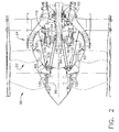
- FIG. 1 is a cross-sectional view of a portion of an exemplary turbine engine assembly 10 having a longitudinal axis 11.
- turbine engine assembly 10 includes a core gas turbine engine 12 generally defined by a frame 13.
- a low-pressure turbine 14 is coupled axially aft of core gas turbine engine 12 and a counter-rotating fan assembly 16 is coupled axially forward of core gas turbine engine 12.
- Core gas turbine engine 12 includes an outer casing 20 that defines an annular core engine inlet 22. Casing 20 surrounds a low-pressure booster compressor 24 to facilitate increasing the pressure of the incoming air to a first pressure level.
- core gas turbine engine 12 is a core CFM56 gas turbine engine available from General Electric Aircraft Engines, Cincinnati, Ohio.
- a high-pressure, multi-stage, axial-flow compressor 26 receives pressurized air from booster compressor 24 and further increases the pressure of the air to a second, higher pressure level.
- the high-pressure air is channeled to a combustor 28 and is mixed with fuel.
- the fuel-air mixture is ignited to raise the temperature and energy level of the pressurized air.
- the high energy combustion products flow to a first or high-pressure turbine 30 for driving compressor 26 through a first rotatable drive shaft 32, and then to second or low-pressure turbine 14 to facilitate driving counter-rotating fan assembly 16 and booster compressor 24 through a second rotatable drive shaft 34 that is coupled coaxially with first drive shaft 32.
- the combustion products leave turbine engine assembly 10 through an exhaust nozzle 36 to provide propulsive jet thrust.
- Counter-rotating fan assembly 16 includes a first or forward fan assembly 50 and a second or an aft fan assembly 52 configured to rotate about longitudinal axis 11.
- the terms "forward fan” and “aft fan” are used herein to indicate that fan assembly 50 is coupled axially upstream from fan assembly 52.
- fan assemblies 50 and 52 are positioned at a forward end of core gas turbine engine 12, as shown in Figures 1-3.
- fan assemblies 50 and 52 are positioned at an aft end of core gas turbine engine 12.
- Fan assemblies 50 and 52 each includes at least one row of rotor blades 60 and 62, respectively, and are positioned within a nacelle 64. Rotor blades 60 are coupled to rotor disk 66 and rotor blades 62 are coupled to rotor disk 68.
- booster compressor 24 includes a plurality of rows of rotor blades 70 that are coupled to a respective rotor disk 72.
- Booster compressor 24 is positioned aft of an inlet guide vane assembly 74 and is coupled to aft fan assembly 52 such that booster compressor 24 rotates at a rotational speed that is substantially equal to a rotational speed of aft fan assembly 52.
- booster compressor 24 is shown as having only three rows of rotor blades 70, booster compressor 24 may have any suitable number and/or rows of rotor blades 70, such as a single row of rotor blades 70 or a plurality of rows of rotor blades 70 that are interdigitated with a plurality of rows of guide vanes 76.
- inlet guide vanes 76 are fixedly or securely coupled to a booster case 78.
- rotor blades 70 are rotatably coupled to rotor disk 72 such that inlet guide vanes 76 are movable during engine operation to facilitate varying a quantity of air channeled through booster compressor 24.
- turbine engine assembly 10 does not include booster compressor 24.
- low-pressure turbine 14 is coupled to forward fan assembly 50 through shaft 34 such that forward fan assembly 50 rotates in a first rotational direction 80.
- Aft fan assembly 52 is coupled to drive shaft 34 and/or low-pressure turbine 14 such that aft fan assembly 52 rotates in an opposite second rotational direction 82.
- FIG. 2 is a schematic diagram of a portion of counter-rotating fan assembly 16 shown in Figure 1.
- first fan assembly 50 includes a cone 84 positioned about longitudinal axis 11.
- Cone 84 is connected at a first or forward end 86 to rotor disk 66 and at a second or aft end 88 to drive shaft 34, as shown in Figure 2.
- Second fan assembly 52 includes a cone 90 positioned coaxially about at least a portion of cone 84 along longitudinal axis 11.
- Cone 90 is coupled at a first or forward end 92 to rotor disk 68 and at a second or aft end 94 to an output of a gearbox 100 and/or to aft end 88 of cone 84 via a rolling bearing assembly, as described in greater detailed below.
- FIG 3 is a schematic diagram of a portion of the counter-rotating fan assembly 16 shown in Figure 2.
- counter-rotating fan assembly 16 also includes a gearbox 100 that is coupled between aft fan assembly 52 and drive shaft 34 to facilitate rotating aft fan assembly 52 in opposite rotational direction 82 with respect to rotational direction 80 in which forward fan assembly 50 rotates.
- Gearbox 100 has a generally toroidal shape and is configured to be positioned circumferentially about drive shaft 34 to extend substantially about drive shaft 34.
- gearbox 100 includes a support structure 102, at least one gear 103 coupled within support structure 102, an input 104 and an output 106.
- gearbox 100 has a gear ratio of approximately 2.0 to 1 such that forward fan assembly 50 rotates at a rotational speed that is approximately twice the rotational speed of aft fan assembly 52.
- forward fan assembly 50 rotates with a rotational speed that is between approximately 0.67 and approximately 2.1 times faster than the rotational speed of aft fan assembly 52.
- forward fan assembly 50 may rotate at a rotational speed greater than, equal to or less than the rotational speed of aft fan assembly 52.
- a first bearing assembly such as thrust bearing assembly 110 as shown in Figures 1-3, is positioned about drive shaft 34 and/or longitudinal axis 11. Thrust bearing assembly 110 operatively couples and/or is mounted between drive shaft 34 and frame 13 of core gas turbine engine 12.
- thrust bearing assembly 110 includes a radially positioned inner race 111 that is mounted with respect to drive shaft 34. As shown in Figure 3, inner race 111 is mounted to a drive shaft extension 112 operatively coupled to drive shaft 34 so that inner race 111 is rotatable about longitudinal axis 11 with drive shaft 34. In one particular embodiment, drive shaft extension 112 is splined to drive shaft 34. Inner race 111 has a surface 113 defining an inner groove 114 of thrust bearing assembly 110. Surface 113 defining inner groove 114 has a generally arcuate profile.
- Thrust bearing assembly 110 includes a radially positioned outer race 116 securely coupled to frame 13.
- outer race 116 and/or frame 13 acts as a ground for the transfer of thrust loads and/or forces developed or generated by counter-rotating fan assembly 16 and/or booster compressor 24, as discussed in greater detail below.
- Outer race 116 has a surface 117, generally opposing surface 113, which forms an outer groove 118 of thrust bearing assembly 110.
- Surface 117 defining outer groove 118 has a generally arcuate profile.
- At least one roller element, such as a plurality of bearings 119 is movably positioned between inner race 111 and outer race 116. Each bearing 119 is in rolling contact with inner groove 114 and outer groove 118 to allow drive shaft 34 to rotate freely with respect to gearbox 100.
- a second bearing assembly such as thrust bearing assembly 120
- thrust bearing assembly 120 operatively couples and/or is mounted between a forward end portion of first fan assembly 50, such as at or near forward end 86 of cone 84, and a forward end portion of second fan assembly 52, such as at or near forward end 92 of cone 90.
- thrust bearing assembly 120 includes a radially positioned inner race 122 that is mounted with respect to an outer surface of cone 84.
- inner race 122 is mounted to cone 84 so that inner race 122 is rotatable about longitudinal axis 11 with first fan assembly 50.
- Inner race 122 has a surface 123 defining an inner groove 124 of thrust bearing assembly 110.
- Surface 123 defining inner groove 124 has a generally arcuate profile.
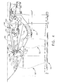
- Thrust bearing assembly 120 includes a radially positioned outer race 126 that is mounted with respect to an inner surface of cone 90. As shown in Figure 4, inner race 122 is mounted to cone 90 so that outer race 126 is rotatable about longitudinal axis 11 with second fan assembly 52. Outer race 126 has a surface 127, generally opposing surface 123, which forms an outer groove 128 of thrust bearing assembly 120. Surface 127 defining outer groove 128 has a generally arcuate profile. At least one roller element, such as a plurality of bearings 129, is movably positioned between inner race 122 and outer race 126. Each bearing 129 is in rolling contact with inner groove 124 and outer groove 128 to facilitate relative rotational movement of first fan assembly 50 and/or second fan assembly 52.
- thrust bearing assemblies 110 and/or 120 facilitate maintaining forward fan assembly 50 and/or aft fan assembly 52 in a relatively fixed axial position.
- thrust loads and/or forces generated by first fan assembly 50 are transferred directly from first fan assembly 50 to first thrust bearing assembly 110.
- thrust loads and/or forces generated by second fan assembly 52 and/or booster compressor 24 during operation are transferred from second fan assembly 52 and/or booster compressor 24 to second thrust bearing assembly 120 and from second thrust bearing assembly 120 through drive shaft 34 to first thrust bearing assembly 110.
- the transfer of thrust loads and/or forces through gearbox 100, operatively coupled to second fan assembly 52 is prevented or limited.
- any suitable bearing assembly known to those skilled in the art and guided by the teachings herein provided can be used for or in addition to bearing assembly 110 and/or bearing assembly 120.
- a bearing assembly such as roller bearing assembly 130
- roller bearing assembly 130 is positioned about the outer surface of cone 90 at or near forward end 92, as shown in Figure 4.
- Roller bearing assembly 130 is connected between frame 13 and forward end 92.
- roller bearing assembly 130 acts as a differential bearing assembly in combination with thrust bearing assembly 120 to support second fan assembly 52 and/or transfer thrust loads and/or forces from second fan assembly 52 to frame 13.
- roller bearing assembly 130 includes an inner race 132 that is mounted with respect to cone 90, as shown in Figure 4.
- Inner race 132 is mounted to forward end 92 of cone 90 so that inner race 132 is rotatable about longitudinal axis 11 with second fan assembly 52.
- Inner race 132 has a surface 133 defining an inner groove 134 of roller bearing assembly 130.
- Roller bearing assembly 130 includes an outer race 136 that is securely coupled to frame 13.
- outer race 136 is securely coupled with respect to structural support member 15 and/or frame 13.
- Structural support member 15 and/or frame 13 acts as a ground for the transfer of thrust loads and/or forces developed or generated by counter-rotating fan assembly 16 and/or booster compressor 24.
- Outer race 136 has a surface 137, generally opposing surface 133, which forms an outer groove 138 of roller bearing assembly 130.
- At least one roller element, such as a plurality of rollers 139 is movably positioned between inner race 132 and outer race 136. Each roller 139 is in rolling contact with inner groove 134 and outer groove 138.
- a bearing assembly such as roller bearing assembly 140, is positioned about the outer surface of cone 84 at or near aft end 88, as shown in Figure 3.
- Roller bearing assembly 140 is connected between cone 84 and cone 90.
- Roller bearing assembly 140 includes an inner race 142 that is mounted with respect to aft end 88, as shown in Figure 2.
- Inner race 142 is mounted to cone 84 so that inner race 142 is rotatable about longitudinal axis 11 with first fan assembly 50.
- Inner race 142 has a surface 143 defining an inner groove 144 of roller bearing assembly 140.
- Roller bearing assembly 140 includes an outer race 146 that is mounted with respect to aft end 94 of cone 90, as shown in Figure 3. Outer race 146 is mounted to cone 90 so that outer race 146 is rotatable about longitudinal axis 11 with second fan assembly 52. Outer race 146 has a surface 147, generally opposing surface 143, which forms an outer groove 148 of roller bearing assembly 140. At least one roller element, such as a plurality of rollers 149, is movably positioned between inner race 142 and outer race 146. Each roller 149 is in rolling contact with inner groove 144 and outer groove 148 to facilitate relative rotational movement of cone 84 and/or cone 90.
- roller bearing assemblies 130 and 140 facilitate providing rotational support to aft fan assembly 52 such that aft fan assembly 52 can rotate freely with respect to forward fan assembly 50. Accordingly, roller bearing assemblies 130 and 140 facilitate maintaining aft fan assembly 52 in a relatively fixed radial position within counter-rotating fan assembly 16.
- any suitable bearing assembly known to those skilled in the art and guided by the teachings herein provided can be used for or in addition to bearing assembly 130 and/or bearing assembly 140.
- gearbox 100 is connected to a fixed or stationary component of gas turbine engine 10, such as frame 13 of core turbine engine 12, as shown in Figure 3.
- Gearbox input 104 is rotatably coupled to second drive shaft 34 through drive shaft extension 112 that is splined to drive shaft 34.
- Gearbox output 106 is rotatably coupled to aft fan assembly 52 through an output structure 160.
- a first end of output structure 160 is splined to gearbox output 106 and a second end of output structure 160 is coupled to aft fan forward shaft 168 to facilitate driving aft fan assembly 52.
- gas turbine engine assembly 10 includes a spline system 200 for mounting gearbox 100 to counter-rotating fan assembly 16.
- Gearbox 100 is fixedly or securely coupled to frame 13 of core gas turbine engine 12, for example at gearbox support structure 102.
- Spline system 200 isolates gearbox 100 from first fan assembly 50 and/or second fan assembly 52 to prevent or limit thrust loads and/or forces exerted on gearbox 100 as a result of counter-rotating fan assembly 16 operation.
- First fan assembly 50 is rotatably coupled to input 104 such that first fan assembly 50 rotates in a first direction, as indicated by rotational arrow 80 in Figure 1.
- Second fan assembly 52 is rotatably coupled to output 106 such that second fan assembly 52 rotates in a second direction, as indicated by rotational arrow 82 in Figure 1, opposite the first direction.
- spline system 200 includes a plurality of spline assemblies, such as spline assembly 202, 204, 206 and/or 208.
- a first spline assembly 202 couples input 104 to drive shaft extension 112.
- Drive shaft extension 112 includes a first portion 210 and a second portion 212, as shown in Figure 3.
- First spline assembly 202 couples input 104 to first portion 10 and a second spline assembly 204, the same or similar to first spline assembly 202, couples first portion 210 to second portion 212 to rotatably couple input 104 to drive shaft 34.
- second spline assembly 204 facilitates movement of thrust bearing assembly 110 with respect to gearbox 100 in the axial direction, i.e., along or parallel with longitudinal axis 11 of turbine engine assembly 10.
- spline assembly 204 includes a member forming a plurality of splines positioned about a periphery of the member.
- the member connected to second portion 212 of drive shaft extension 112, is positionable within a cavity formed in a cooperating housing, connected to first portion 210, such that the plurality of splines mesh or interfere with slots formed on an inner periphery of the housing to transfer torsional loads and/or forces from second portion 212 to first portion 210 of drive shaft extension 112.
- the member is positioned within the cooperating housing to facilitate movement of the member within the housing in an axial direction, e.g., along or parallel with longitudinal axis 11, which facilitates axial movement of second portion 212 with respect to first portion 210.
- each spline assembly 204, 206 and 208 are the same or similar, as described above with reference to spline assembly 204.
- a third spline assembly 206 slidably couples output 106 to output structure 160.
- Third spline assembly 206 facilitates axial movement of aft fan forward shaft 168 with respect to gearbox 100.
- a fourth spline assembly 208 slidably couples second portion 212 of drive shaft extension 112 to drive shaft 34.
- spline assemblies 202, 204, 206 and/or 208 pass only torsional or torque loads and/or forces to gearbox 100 such that gearbox 100 remains in a substantially fixed position with respect to the frame of low-pressure turbine 14.
- first portion 210 includes a radially inner portion 230 that is coupled to input 104 through spline assembly 202 and a radially outer portion 232 that is coupled to second portion 212 through spline assembly 204.
- First portion 210 has a first thickness at or near inner portion 230 and a second thickness at or near outer portion 232, which is less than first thickness.
- a thickness of first portion 210 gradually decreases from radially inner portion 230 to radially outer portion 232. The second thickness is selected such that first portion 230 will separate from second portion 232, i.e.
- first portion 210 will break, when first portion 210 is subjected to a determined torsional load and/or force.
- relatively large radial loads and/or forces may be applied to aft fan assembly 52.
- first portion 210 breaks such that forward fan assembly 50 continues to operate as aft fan assembly 52 freewheels.
- gearbox 100 is located within a sump 170 at least partially defined between output structure 160 and structural support member 15 configured to support aft fan assembly 52. During operation, gearbox 100 is at least partially submerged within lubrication fluid contained in sump 170 to continuously lubricate gearbox 100 during engine operation.
- the gas turbine engine assembly described herein includes a counter-rotating fan assembly having a geared single rotation low-pressure turbine.
- the assembly facilitates reducing at least some of the complexities associated with known counter-rotating low-pressure turbines. More specifically, the gas turbine engine assembly described herein includes a front fan that is rotatably coupled to a single rotation low-pressure turbine, and an aft fan and booster assembly that are rotatably coupled together, and driven by, the low-pressure turbine via a gearbox. Moreover, the aft fan assembly and booster assembly are driven at the same speed, which, in one embodiment, is approximately one-half the front fan speed.
- gas turbine engine assembly described herein is configured such that approximately 40% of power generated by the low-pressure turbine is transmitted through the gearbox to the aft fan assembly to facilitate reducing gear losses. Therefore, in the event of a gearbox failure, the aft fan assembly will cease to rotate. However, the front fan assembly will continue to rotate because the front fan assembly is directly driven by the low-pressure turbine.
- a spline system of the present invention facilitates preventing or limiting axial loads developed as a result of thrust loads and/or forces generated by the counter-rotating fan assembly and/or the coupled booster compressor to be transferred to the gearbox.
- the spline system includes spline assemblies that couple the gearbox to the drive shaft and/or components of the counter-rotating fan assembly. The spline assemblies transfer torsional loads and/or forces to the gearbox but prevent or limit axial loads and/or forces from being transferred to the gearbox.
- the gearbox remains substantially fixed with respect to the gas turbine engine assembly frame. As a result, the gearbox is only subjected to torsional loads and/or forces.
- Exemplary embodiments of a gas turbine engine assembly and methods of assembly the gas turbine engine assembly are described above in detail.
- the assembly and method are not limited to the specific embodiments described herein, but rather, components of the assembly and/or steps of the method may be utilized independently and separately from other components and/or steps described herein. Further, the described assembly components and/or the method steps can also be defined in, or used in combination with, other assemblies and/or methods, and are not limited to practice with only the assembly and/or method as described herein.
- turbine engine assembly 11 longitudinal axis 12 core gas turbine engine 13 frame 14 low-pressure turbine 15 structural support member 16 rotating fan assembly 20 outer casing 22 engine inlet 24 booster compressor 26 compressor 28 combustor 30 high-pressure turbine 32 first rotatable drive shaft 34 second rotatable drive shaft 36 exhaust nozzle 50 fan assemblies 52 aft fan assembly 60 rotor blades 62 rotor blades 64 nacelle 66 rotor disk 68 rotor disk 70 rotor blades 72 rotor disk 74 inlet guide vane assembly 76 inlet guide vanes 78 booster case 80 first rotational direction 82 second rotational direction 84 cone 86 first or forward end 88 second or aft end 90 cone 92 first or forward end 94 second or aft end 100 gearbox 102 housing 103 gear 104 input 106 output 110 thrust bearing assembly 111 inner race 112 bearing support structure 113 surface 114 inner groove 116 outer race 117 surface 118 outer groove 119 plurality of bearings 120 thrust bearing assembly 122 inner race 123 surface 124 inner groove
Abstract
Description
- This invention relates generally to gas turbine engines, and more specifically to gas turbine engine assemblies and methods of assembling the same.
- At least some known gas turbine engines include a forward fan, a core engine, and a power turbine. The core engine includes at least one compressor, a combustor, a high-pressure turbine and a low-pressure turbine coupled together in a serial flow relationship. More specifically, the compressor and high-pressure turbine are coupled through a shaft to define a high-pressure rotor assembly. Air entering the core engine is mixed with fuel and ignited to form a high energy gas stream. The high energy gas stream flows through the high-pressure turbine to rotatably drive the high-pressure turbine such that the shaft, in turn, rotatably drives the compressor.
- The gas stream expands as it flows through the low-pressure turbine positioned forward of the high-pressure turbine. The low-pressure turbine includes a rotor assembly having a fan coupled to a drive shaft. The low-pressure turbine rotatably drives the fan through the drive shaft. To facilitate increasing engine efficiency, at least one known gas turbine engine includes a counter-rotating low-pressure turbine that is coupled to a counter-rotating fan and/or a counter-rotating booster compressor.
- An outer rotating spool, a rotating frame, a mid-turbine frame, and two concentric shafts, are installed within the gas turbine engine to facilitate supporting the counter-rotating low-pressure turbine. The installation of the aforementioned components also enables a first fan assembly to be coupled to a first turbine and a second fan assembly to be coupled to a second turbine such that the first fan assembly and the second fan assembly each rotate in the same rotational direction as the first turbine and the second turbine, respectively. Accordingly, the overall weight, design complexity and/or manufacturing costs of such an engine are increased.
- In one embodiment, the present invention provides a method for assembling a gas turbine engine. The method includes providing a core gas turbine engine at least partially defined by a frame and having a drive shaft rotatable about a longitudinal axis of the core gas turbine engine. A low-pressure turbine is coupled to a core turbine engine. A counter-rotating fan assembly including a first fan assembly and a second fan assembly is coupled to the low-pressure turbine. A booster compressor is coupled to the second fan assembly. A gearbox is securely coupled to the frame so that the gearbox is circumferentially positioned about the drive shaft. The first fan assembly is rotatably mounted to an input of the gearbox such that the first fan assembly rotates in a first direction. The second fan assembly is rotatably coupled to an output of the gearbox such that the second fan assembly rotates in a second direction opposite the first direction.
- In another embodiment, a spline system for operatively coupling a gearbox to a counter-rotating fan assembly is provided. The spline system includes a first spline assembly coupling an input of said gearbox to a bearing support structure. A second spline assembly slidably couples a first portion of the bearing support structure to a second portion of the bearing support structure. A third spline assembly slidably couples an output of the gearbox to an output structure. The spline system isolates the gearbox from axial loads generated by the counter-rotating fan assembly.
- In a further embodiment, a turbine engine assembly is provided. The turbine engine assembly includes a core turbine engine at least partially defined by a frame and having a drive shaft rotatable about a longitudinal axis of the core turbine engine. A low-pressure turbine is coupled to the core turbine engine. A gearbox is securely coupled with respect to the low-pressure turbine. A first fan assembly is coupled to an input of the gearbox. The first fan assembly is rotatable in a first rotational direction. A second fan assembly is coupled to an output of the gearbox. The second fan assembly is rotatable in a second rotational direction opposite said first direction. A spline system isolates the gearbox from axial loads generated by at least one of the first fan assembly and the second fan assembly.
- Embodiments of the present invention will now be described, by way of example only, with reference to the accompanying drawings, in which:
- Figure 1 is a cross-sectional view of a portion of an exemplary turbine engine assembly;
- Figure 2 is an enlarged cross-sectional view of a portion of a counter-rotating fan assembly shown in Figure 1;
- Figure 3 is an enlarged cross-sectional view of a portion of the counter-rotating fan assembly shown in Figure 2; and
- Figure 4 is an enlarged cross-sectional view of a portion of the counter-rotating fan assembly shown in Figure 2.
- Figure 1 is a cross-sectional view of a portion of an exemplary
turbine engine assembly 10 having alongitudinal axis 11. In the exemplary embodiment,turbine engine assembly 10 includes a coregas turbine engine 12 generally defined by a frame 13. A low-pressure turbine 14 is coupled axially aft of coregas turbine engine 12 and acounter-rotating fan assembly 16 is coupled axially forward of coregas turbine engine 12. - Core
gas turbine engine 12 includes anouter casing 20 that defines an annularcore engine inlet 22. Casing 20 surrounds a low-pressure booster compressor 24 to facilitate increasing the pressure of the incoming air to a first pressure level. In one embodiment, coregas turbine engine 12 is a core CFM56 gas turbine engine available from General Electric Aircraft Engines, Cincinnati, Ohio. - A high-pressure, multi-stage, axial-
flow compressor 26 receives pressurized air frombooster compressor 24 and further increases the pressure of the air to a second, higher pressure level. The high-pressure air is channeled to acombustor 28 and is mixed with fuel. The fuel-air mixture is ignited to raise the temperature and energy level of the pressurized air. The high energy combustion products flow to a first or high-pressure turbine 30 for drivingcompressor 26 through a firstrotatable drive shaft 32, and then to second or low-pressure turbine 14 to facilitate drivingcounter-rotating fan assembly 16 andbooster compressor 24 through a secondrotatable drive shaft 34 that is coupled coaxially withfirst drive shaft 32. After driving low-pressure turbine 14, the combustion products leaveturbine engine assembly 10 through anexhaust nozzle 36 to provide propulsive jet thrust. -
Counter-rotating fan assembly 16 includes a first orforward fan assembly 50 and a second or anaft fan assembly 52 configured to rotate aboutlongitudinal axis 11. The terms "forward fan" and "aft fan" are used herein to indicate thatfan assembly 50 is coupled axially upstream fromfan assembly 52. In one embodiment,fan assemblies gas turbine engine 12, as shown in Figures 1-3. In an alternative embodiment,fan assemblies gas turbine engine 12.Fan assemblies rotor blades nacelle 64.Rotor blades 60 are coupled torotor disk 66 androtor blades 62 are coupled torotor disk 68. - In one embodiment,
booster compressor 24 includes a plurality of rows ofrotor blades 70 that are coupled to a respective rotor disk 72.Booster compressor 24 is positioned aft of an inletguide vane assembly 74 and is coupled toaft fan assembly 52 such thatbooster compressor 24 rotates at a rotational speed that is substantially equal to a rotational speed ofaft fan assembly 52. Althoughbooster compressor 24 is shown as having only three rows ofrotor blades 70,booster compressor 24 may have any suitable number and/or rows ofrotor blades 70, such as a single row ofrotor blades 70 or a plurality of rows ofrotor blades 70 that are interdigitated with a plurality of rows ofguide vanes 76. In one embodiment,inlet guide vanes 76 are fixedly or securely coupled to abooster case 78. In an alternative embodiment,rotor blades 70 are rotatably coupled to rotor disk 72 such thatinlet guide vanes 76 are movable during engine operation to facilitate varying a quantity of air channeled throughbooster compressor 24. In another alternative embodiment,turbine engine assembly 10 does not includebooster compressor 24. - As shown in Figure 1, low-
pressure turbine 14 is coupled toforward fan assembly 50 throughshaft 34 such thatforward fan assembly 50 rotates in a firstrotational direction 80.Aft fan assembly 52 is coupled to driveshaft 34 and/or low-pressure turbine 14 such thataft fan assembly 52 rotates in an opposite secondrotational direction 82. - Figure 2 is a schematic diagram of a portion of
counter-rotating fan assembly 16 shown in Figure 1. In one embodiment,first fan assembly 50 includes acone 84 positioned aboutlongitudinal axis 11.Cone 84 is connected at a first or forward end 86 torotor disk 66 and at a second oraft end 88 to driveshaft 34, as shown in Figure 2.Second fan assembly 52 includes acone 90 positioned coaxially about at least a portion ofcone 84 alonglongitudinal axis 11.Cone 90 is coupled at a first orforward end 92 torotor disk 68 and at a second oraft end 94 to an output of agearbox 100 and/or toaft end 88 ofcone 84 via a rolling bearing assembly, as described in greater detailed below. - Figure 3 is a schematic diagram of a portion of the
counter-rotating fan assembly 16 shown in Figure 2. In one embodiment,counter-rotating fan assembly 16 also includes agearbox 100 that is coupled betweenaft fan assembly 52 and driveshaft 34 to facilitate rotatingaft fan assembly 52 in oppositerotational direction 82 with respect torotational direction 80 in whichforward fan assembly 50 rotates.Gearbox 100 has a generally toroidal shape and is configured to be positioned circumferentially aboutdrive shaft 34 to extend substantially aboutdrive shaft 34. As shown in Figure 3,gearbox 100 includes asupport structure 102, at least onegear 103 coupled withinsupport structure 102, aninput 104 and anoutput 106. - In one embodiment,
gearbox 100 has a gear ratio of approximately 2.0 to 1 such thatforward fan assembly 50 rotates at a rotational speed that is approximately twice the rotational speed ofaft fan assembly 52. In another embodiment,forward fan assembly 50 rotates with a rotational speed that is between approximately 0.67 and approximately 2.1 times faster than the rotational speed ofaft fan assembly 52. In this embodiment,forward fan assembly 50 may rotate at a rotational speed greater than, equal to or less than the rotational speed ofaft fan assembly 52. - In one embodiment, a first bearing assembly, such as
thrust bearing assembly 110 as shown in Figures 1-3, is positioned aboutdrive shaft 34 and/orlongitudinal axis 11.Thrust bearing assembly 110 operatively couples and/or is mounted betweendrive shaft 34 and frame 13 of coregas turbine engine 12. Referring further to Figure 3, in one embodiment, thrustbearing assembly 110 includes a radially positionedinner race 111 that is mounted with respect to driveshaft 34. As shown in Figure 3,inner race 111 is mounted to adrive shaft extension 112 operatively coupled to driveshaft 34 so thatinner race 111 is rotatable aboutlongitudinal axis 11 withdrive shaft 34. In one particular embodiment, driveshaft extension 112 is splined to driveshaft 34.Inner race 111 has asurface 113 defining aninner groove 114 ofthrust bearing assembly 110.Surface 113 defininginner groove 114 has a generally arcuate profile. -
Thrust bearing assembly 110 includes a radially positionedouter race 116 securely coupled to frame 13. In one embodiment,outer race 116 and/or frame 13 acts as a ground for the transfer of thrust loads and/or forces developed or generated bycounter-rotating fan assembly 16 and/orbooster compressor 24, as discussed in greater detail below.Outer race 116 has a surface 117, generally opposingsurface 113, which forms anouter groove 118 ofthrust bearing assembly 110. Surface 117 definingouter groove 118 has a generally arcuate profile. At least one roller element, such as a plurality ofbearings 119, is movably positioned betweeninner race 111 andouter race 116. Each bearing 119 is in rolling contact withinner groove 114 andouter groove 118 to allowdrive shaft 34 to rotate freely with respect togearbox 100. - Referring to Figure 4, a second bearing assembly, such as
thrust bearing assembly 120, is positioned radially aboutlongitudinal axis 11. In one embodiment, thrustbearing assembly 120 operatively couples and/or is mounted between a forward end portion offirst fan assembly 50, such as at or near forward end 86 ofcone 84, and a forward end portion ofsecond fan assembly 52, such as at or nearforward end 92 ofcone 90. In one embodiment, thrustbearing assembly 120 includes a radially positionedinner race 122 that is mounted with respect to an outer surface ofcone 84. As shown in Figure 4,inner race 122 is mounted tocone 84 so thatinner race 122 is rotatable aboutlongitudinal axis 11 withfirst fan assembly 50.Inner race 122 has asurface 123 defining aninner groove 124 ofthrust bearing assembly 110.Surface 123 defininginner groove 124 has a generally arcuate profile. -
Thrust bearing assembly 120 includes a radially positionedouter race 126 that is mounted with respect to an inner surface ofcone 90. As shown in Figure 4,inner race 122 is mounted tocone 90 so thatouter race 126 is rotatable aboutlongitudinal axis 11 withsecond fan assembly 52.Outer race 126 has asurface 127, generally opposingsurface 123, which forms anouter groove 128 ofthrust bearing assembly 120.Surface 127 definingouter groove 128 has a generally arcuate profile. At least one roller element, such as a plurality ofbearings 129, is movably positioned betweeninner race 122 andouter race 126. Each bearing 129 is in rolling contact withinner groove 124 andouter groove 128 to facilitate relative rotational movement offirst fan assembly 50 and/orsecond fan assembly 52. - In one embodiment, thrust bearing
assemblies 110 and/or 120 facilitate maintaining forwardfan assembly 50 and/oraft fan assembly 52 in a relatively fixed axial position. During operation ofcounter-rotating fan assembly 16, thrust loads and/or forces generated byfirst fan assembly 50 are transferred directly fromfirst fan assembly 50 to firstthrust bearing assembly 110. Further, thrust loads and/or forces generated bysecond fan assembly 52 and/orbooster compressor 24 during operation are transferred fromsecond fan assembly 52 and/orbooster compressor 24 to secondthrust bearing assembly 120 and from secondthrust bearing assembly 120 throughdrive shaft 34 to firstthrust bearing assembly 110. As a result of transferring thrust loads and/or forces to thrustbearing assembly 110 and/or thrustbearing assembly 120, the transfer of thrust loads and/or forces throughgearbox 100, operatively coupled tosecond fan assembly 52, is prevented or limited. In alternative embodiments, any suitable bearing assembly known to those skilled in the art and guided by the teachings herein provided can be used for or in addition to bearingassembly 110 and/or bearingassembly 120. - In one embodiment, a bearing assembly, such as
roller bearing assembly 130, is positioned about the outer surface ofcone 90 at or nearforward end 92, as shown in Figure 4.Roller bearing assembly 130 is connected between frame 13 andforward end 92. In one embodiment,roller bearing assembly 130 acts as a differential bearing assembly in combination withthrust bearing assembly 120 to supportsecond fan assembly 52 and/or transfer thrust loads and/or forces fromsecond fan assembly 52 to frame 13. In one embodiment,roller bearing assembly 130 includes an inner race 132 that is mounted with respect tocone 90, as shown in Figure 4. Inner race 132 is mounted toforward end 92 ofcone 90 so that inner race 132 is rotatable aboutlongitudinal axis 11 withsecond fan assembly 52. Inner race 132 has a surface 133 defining an inner groove 134 ofroller bearing assembly 130. -
Roller bearing assembly 130 includes an outer race 136 that is securely coupled to frame 13. In one embodiment, outer race 136 is securely coupled with respect tostructural support member 15 and/or frame 13.Structural support member 15 and/or frame 13 acts as a ground for the transfer of thrust loads and/or forces developed or generated bycounter-rotating fan assembly 16 and/orbooster compressor 24. Outer race 136 has a surface 137, generally opposing surface 133, which forms an outer groove 138 ofroller bearing assembly 130. At least one roller element, such as a plurality ofrollers 139, is movably positioned between inner race 132 and outer race 136. Eachroller 139 is in rolling contact with inner groove 134 and outer groove 138. - In one embodiment, a bearing assembly, such as
roller bearing assembly 140, is positioned about the outer surface ofcone 84 at or nearaft end 88, as shown in Figure 3.Roller bearing assembly 140 is connected betweencone 84 andcone 90.Roller bearing assembly 140 includes aninner race 142 that is mounted with respect toaft end 88, as shown in Figure 2.Inner race 142 is mounted tocone 84 so thatinner race 142 is rotatable aboutlongitudinal axis 11 withfirst fan assembly 50.Inner race 142 has asurface 143 defining an inner groove 144 ofroller bearing assembly 140. -
Roller bearing assembly 140 includes anouter race 146 that is mounted with respect toaft end 94 ofcone 90, as shown in Figure 3.Outer race 146 is mounted tocone 90 so thatouter race 146 is rotatable aboutlongitudinal axis 11 withsecond fan assembly 52.Outer race 146 has asurface 147, generally opposingsurface 143, which forms anouter groove 148 ofroller bearing assembly 140. At least one roller element, such as a plurality ofrollers 149, is movably positioned betweeninner race 142 andouter race 146. Eachroller 149 is in rolling contact with inner groove 144 andouter groove 148 to facilitate relative rotational movement ofcone 84 and/orcone 90. - In this embodiment,
roller bearing assemblies aft fan assembly 52 such thataft fan assembly 52 can rotate freely with respect toforward fan assembly 50. Accordingly,roller bearing assemblies aft fan assembly 52 in a relatively fixed radial position withincounter-rotating fan assembly 16. In alternative embodiments, any suitable bearing assembly known to those skilled in the art and guided by the teachings herein provided can be used for or in addition to bearingassembly 130 and/or bearingassembly 140. - In one embodiment,
gearbox 100 is connected to a fixed or stationary component ofgas turbine engine 10, such as frame 13 ofcore turbine engine 12, as shown in Figure 3.Gearbox input 104 is rotatably coupled tosecond drive shaft 34 throughdrive shaft extension 112 that is splined to driveshaft 34.Gearbox output 106 is rotatably coupled toaft fan assembly 52 through anoutput structure 160. A first end ofoutput structure 160 is splined togearbox output 106 and a second end ofoutput structure 160 is coupled to aft fanforward shaft 168 to facilitate drivingaft fan assembly 52. - Referring to Figure 3, in one embodiment, gas
turbine engine assembly 10 includes aspline system 200 for mountinggearbox 100 tocounter-rotating fan assembly 16.Gearbox 100 is fixedly or securely coupled to frame 13 of coregas turbine engine 12, for example atgearbox support structure 102.Spline system 200 isolatesgearbox 100 fromfirst fan assembly 50 and/orsecond fan assembly 52 to prevent or limit thrust loads and/or forces exerted ongearbox 100 as a result ofcounter-rotating fan assembly 16 operation.First fan assembly 50 is rotatably coupled to input 104 such thatfirst fan assembly 50 rotates in a first direction, as indicated byrotational arrow 80 in Figure 1.Second fan assembly 52 is rotatably coupled tooutput 106 such thatsecond fan assembly 52 rotates in a second direction, as indicated byrotational arrow 82 in Figure 1, opposite the first direction. - As shown in Figure 3,
spline system 200 includes a plurality of spline assemblies, such asspline assembly first spline assembly 202 couples input 104 to driveshaft extension 112. Driveshaft extension 112 includes afirst portion 210 and asecond portion 212, as shown in Figure 3.First spline assembly 202 couples input 104 tofirst portion 10 and asecond spline assembly 204, the same or similar tofirst spline assembly 202, couplesfirst portion 210 tosecond portion 212 to rotatablycouple input 104 to driveshaft 34. Further,second spline assembly 204 facilitates movement ofthrust bearing assembly 110 with respect togearbox 100 in the axial direction, i.e., along or parallel withlongitudinal axis 11 ofturbine engine assembly 10. - In one embodiment,
spline assembly 204 includes a member forming a plurality of splines positioned about a periphery of the member. The member, connected tosecond portion 212 ofdrive shaft extension 112, is positionable within a cavity formed in a cooperating housing, connected tofirst portion 210, such that the plurality of splines mesh or interfere with slots formed on an inner periphery of the housing to transfer torsional loads and/or forces fromsecond portion 212 tofirst portion 210 ofdrive shaft extension 112. Further, the member is positioned within the cooperating housing to facilitate movement of the member within the housing in an axial direction, e.g., along or parallel withlongitudinal axis 11, which facilitates axial movement ofsecond portion 212 with respect tofirst portion 210. - In one particular embodiment, each
spline assembly spline assembly 204. Athird spline assembly 206slidably couples output 106 tooutput structure 160.Third spline assembly 206 facilitates axial movement of aft fanforward shaft 168 with respect togearbox 100. In one embodiment, afourth spline assembly 208 slidably couplessecond portion 212 ofdrive shaft extension 112 to driveshaft 34. During operation,spline assemblies gearbox 100 such thatgearbox 100 remains in a substantially fixed position with respect to the frame of low-pressure turbine 14. - In one embodiment, drive
shaft extension 112 and/oroutput structure 160 include at least one flexible arm compensating for a radial deflection ofgearbox 100. In a particular embodiment,first portion 210 includes a radiallyinner portion 230 that is coupled to input 104 throughspline assembly 202 and a radiallyouter portion 232 that is coupled tosecond portion 212 throughspline assembly 204.First portion 210 has a first thickness at or nearinner portion 230 and a second thickness at or nearouter portion 232, which is less than first thickness. In this particular embodiment, a thickness offirst portion 210 gradually decreases from radiallyinner portion 230 to radiallyouter portion 232. The second thickness is selected such thatfirst portion 230 will separate fromsecond portion 232, i.e.first portion 210 will break, whenfirst portion 210 is subjected to a determined torsional load and/or force. During operation ofengine assembly 10, relatively large radial loads and/or forces may be applied toaft fan assembly 52. To compensate for the relatively large radial loads and/or forces, and to ensure continued engine operation, in one embodimentfirst portion 210 breaks such thatforward fan assembly 50 continues to operate asaft fan assembly 52 freewheels. - During operation, as
second drive shaft 34 rotates,second drive shaft 34 causesinput 104 to rotate in firstrotational direction 80, which subsequently rotatesoutput 106 in opposite secondrotational direction 82. Becauseoutput structure 160 is coupled toaft fan assembly 52,drive shaft 34 causes aftfan assembly 52 to rotate viagearbox 100 in oppositesecond direction 82. In one embodiment,gearbox 100 is located within asump 170 at least partially defined betweenoutput structure 160 andstructural support member 15 configured to supportaft fan assembly 52. During operation,gearbox 100 is at least partially submerged within lubrication fluid contained insump 170 to continuously lubricategearbox 100 during engine operation. - The gas turbine engine assembly described herein includes a counter-rotating fan assembly having a geared single rotation low-pressure turbine. The assembly facilitates reducing at least some of the complexities associated with known counter-rotating low-pressure turbines. More specifically, the gas turbine engine assembly described herein includes a front fan that is rotatably coupled to a single rotation low-pressure turbine, and an aft fan and booster assembly that are rotatably coupled together, and driven by, the low-pressure turbine via a gearbox. Moreover, the aft fan assembly and booster assembly are driven at the same speed, which, in one embodiment, is approximately one-half the front fan speed. Additionally, the gas turbine engine assembly described herein is configured such that approximately 40% of power generated by the low-pressure turbine is transmitted through the gearbox to the aft fan assembly to facilitate reducing gear losses. Therefore, in the event of a gearbox failure, the aft fan assembly will cease to rotate. However, the front fan assembly will continue to rotate because the front fan assembly is directly driven by the low-pressure turbine.
- The above-described gas turbine engine assembly and methods of assembly the gas turbine engine assembly allows the gearbox to be isolated from axial thrusts generated by the counter-rotating fan assembly and/or the coupled booster compressor. More specifically, a spline system of the present invention facilitates preventing or limiting axial loads developed as a result of thrust loads and/or forces generated by the counter-rotating fan assembly and/or the coupled booster compressor to be transferred to the gearbox. The spline system includes spline assemblies that couple the gearbox to the drive shaft and/or components of the counter-rotating fan assembly. The spline assemblies transfer torsional loads and/or forces to the gearbox but prevent or limit axial loads and/or forces from being transferred to the gearbox. Thus, the gearbox remains substantially fixed with respect to the gas turbine engine assembly frame. As a result, the gearbox is only subjected to torsional loads and/or forces.
- Exemplary embodiments of a gas turbine engine assembly and methods of assembly the gas turbine engine assembly are described above in detail. The assembly and method are not limited to the specific embodiments described herein, but rather, components of the assembly and/or steps of the method may be utilized independently and separately from other components and/or steps described herein. Further, the described assembly components and/or the method steps can also be defined in, or used in combination with, other assemblies and/or methods, and are not limited to practice with only the assembly and/or method as described herein.
- While the invention has been described in terms of various specific embodiments, those skilled in the art will recognize that the invention can be practiced with modification within the spirit and scope of the claims.
-
10 turbine engine assembly 11 longitudinal axis 12 core gas turbine engine 13 frame 14 low-pressure turbine 15 structural support member 16 rotating fan assembly 20 outer casing 22 engine inlet 24 booster compressor 26 compressor 28 combustor 30 high-pressure turbine 32 first rotatable drive shaft 34 second rotatable drive shaft 36 exhaust nozzle 50 fan assemblies 52 aft fan assembly 60 rotor blades 62 rotor blades 64 nacelle 66 rotor disk 68 rotor disk 70 rotor blades 72 rotor disk 74 inlet guide vane assembly 76 inlet guide vanes 78 booster case 80 first rotational direction 82 second rotational direction 84 cone 86 first or forward end 88 second or aft end 90 cone 92 first or forward end 94 second or aft end 100 gearbox 102 housing 103 gear 104 input 106 output 110 thrust bearing assembly 111 inner race 112 bearing support structure 113 surface 114 inner groove 116 outer race 117 surface 118 outer groove 119 plurality of bearings 120 thrust bearing assembly 122 inner race 123 surface 124 inner groove 126 outer race 127 surface 128 outer groove 129 plurality of bearings 130 roller bearing assembly 132 inner race 133 surface 134 inner groove 134 inner groove 136 outer race 137 surface 138 outer groove 139 plurality of rollers 140 roller bearing assembly 142 inner race 143 surface 144 inner groove 146 outer race 147 surface 148 outer groove 149 plurality of rollers 160 output structure 168 aft fan forward shaft 170 sump 200 spline system 202 spline assembly 204 second spline assembly 206 third spline assembly 208 fourth spline assembly 210 first portion 212 second portion 230 inner portion 232 outer portion
Claims (10)
- A spline system (200) for operatively coupling a gearbox (100) to a counter-rotating fan assembly (16), said spline system comprising:a first spline assembly (202) coupling an input (104) of said gearbox to a bearing support structure (112);a second spline assembly (204) slidably coupling a first portion (210) of said bearing support structure to a second portion (212) of said bearing support structure; anda third spline assembly (206) slidably coupling an output (106) of said gearbox to an output structure, said spline system isolating said gearbox from axial loads generated by said counter-rotating fan assembly.
- A spline system (200) in accordance with Claim 1 wherein said second spline assembly (204) facilitates axial movement of a first bearing assembly (110) with respect to said gearbox (100).
- A spline system (200) in accordance with Claim 1 wherein said second spline assembly (204) rotatably couples said input (104) to a drive shaft (32) rotatable about a longitudinal axis (11) of a core gas turbine engine (12).
- A spline system (200) in accordance with Claim 1 wherein said third spline assembly (206) provides axial movement of an aft fan (52) forward shaft with respect to said gearbox (100), said aft fan forward shaft coupled to said output (106) structure to facilitate driving an aft fan assembly of said counter-rotating fan assembly (16).
- A spline system (200) in accordance with Claim 1 wherein at least one of said bearing support structure (112) and said output (106) structure includes at least one flexible arm compensating for a radial deflection of said gearbox (100).
- A spline system (200) in accordance with Claim 1 wherein said counter-rotating fan assembly (16) further comprises:a first fan assembly (50) rotatably coupled to said input (104), said first fan assembly rotating in a first direction (80); anda second fan assembly (52) rotatably coupled to said output (106), said second fan assembly rotating in a second direction (82) opposite said first direction.
- A turbine engine assembly (10) comprising:a core turbine engine (12) at least partially defined by a frame (13) and having a drive shaft (32) rotatable about a longitudinal axis (11) of said core turbine engine;a low-pressure turbine (14) coupled to said core turbine engine;a gearbox (100) securely coupling with respect to said low-pressure turbine;a first fan assembly (50) coupled to an input (104) of said gearbox, said first fan assembly rotatable in a first rotational direction (80);a second fan assembly (52) coupled to an output (106) of said gearbox, said second fan assembly rotatable in a second rotational direction (82) opposite said first direction; anda spline system (200) isolating said gearbox from axial loads generated by at least one of said first fan assembly and said second fan assembly.
- A turbine engine assembly (10) in accordance with Claim 7 wherein said spline system (200) rotatably couples said input (104) to said drive shaft (32).
- A turbine engine assembly (10) in accordance with Claim 7 wherein said spline system (200) further comprises:a first spline assembly (202) slidably coupling said first fan assembly (50) to said input (104); anda second spline assembly (204) slidably coupling said second fan assembly (52) to said output (106).
- A turbine engine assembly (10) in accordance with Claim 9 wherein said spline system (200) further comprises a third spline assembly (206) slidably coupling a first portion (210) of a bearing support structure (212) to a second portion of said bearing support structure.
Applications Claiming Priority (1)
| Application Number | Priority Date | Filing Date | Title |
|---|---|---|---|
| US11/254,018 US7493754B2 (en) | 2005-10-19 | 2005-10-19 | Gas turbine engine assembly and methods of assembling same |
Publications (2)
| Publication Number | Publication Date |
|---|---|
| EP1777380A2 true EP1777380A2 (en) | 2007-04-25 |
| EP1777380A3 EP1777380A3 (en) | 2014-04-09 |
Family
ID=37192960
Family Applications (1)
| Application Number | Title | Priority Date | Filing Date |
|---|---|---|---|
| EP06255265.8A Withdrawn EP1777380A3 (en) | 2005-10-19 | 2006-10-12 | Gas turbine engine assembly and methods of assembling same |
Country Status (4)
| Country | Link |
|---|---|
| US (1) | US7493754B2 (en) |
| EP (1) | EP1777380A3 (en) |
| JP (1) | JP5111824B2 (en) |
| CN (1) | CN1952368B (en) |
Cited By (5)
| Publication number | Priority date | Publication date | Assignee | Title |
|---|---|---|---|---|
| WO2014158439A1 (en) * | 2013-03-12 | 2014-10-02 | United Technologies Corporation | Flexible coupling for geared turbine engine |
| EP3144487A1 (en) * | 2015-09-18 | 2017-03-22 | Rolls-Royce plc | A coupling for a geared turbo fan |
| EP3144486A1 (en) * | 2015-09-18 | 2017-03-22 | Rolls-Royce plc | A shafting arrangement for a gas turbine engine |
| US10119465B2 (en) | 2015-06-23 | 2018-11-06 | United Technologies Corporation | Geared turbofan with independent flexible ring gears and oil collectors |
| US11542989B2 (en) | 2017-11-30 | 2023-01-03 | Rolls-Royce Deutschland Ltd & Co Kg | Coupling device for rotably coupling a shaft with a gearbox in a geared turbo fan engine |
Families Citing this family (59)
| Publication number | Priority date | Publication date | Assignee | Title |
|---|---|---|---|---|
| US7726113B2 (en) * | 2005-10-19 | 2010-06-01 | General Electric Company | Gas turbine engine assembly and methods of assembling same |
| US7493753B2 (en) * | 2005-10-19 | 2009-02-24 | General Electric Company | Gas turbine engine assembly and methods of assembling same |
| US7685808B2 (en) * | 2005-10-19 | 2010-03-30 | General Electric Company | Gas turbine engine assembly and methods of assembling same |
| US7526913B2 (en) * | 2005-10-19 | 2009-05-05 | General Electric Company | Gas turbine engine assembly and methods of assembling same |
| US7490461B2 (en) * | 2005-10-19 | 2009-02-17 | General Electric Company | Gas turbine engine assembly and methods of assembling same |
| US7513103B2 (en) * | 2005-10-19 | 2009-04-07 | General Electric Company | Gas turbine engine assembly and methods of assembling same |
| US7603844B2 (en) * | 2005-10-19 | 2009-10-20 | General Electric Company | Gas turbine engine assembly and methods of assembling same |
| US7661260B2 (en) * | 2006-09-27 | 2010-02-16 | General Electric Company | Gas turbine engine assembly and method of assembling same |
| US7832193B2 (en) * | 2006-10-27 | 2010-11-16 | General Electric Company | Gas turbine engine assembly and methods of assembling same |
| US7716914B2 (en) * | 2006-12-21 | 2010-05-18 | General Electric Company | Turbofan engine assembly and method of assembling same |
| US10151248B2 (en) | 2007-10-03 | 2018-12-11 | United Technologies Corporation | Dual fan gas turbine engine and gear train |
| US8205432B2 (en) * | 2007-10-03 | 2012-06-26 | United Technologies Corporation | Epicyclic gear train for turbo fan engine |
| EP2123884B1 (en) * | 2008-05-13 | 2015-03-04 | Rolls-Royce Corporation | Dual clutch arrangement |
| US20100005810A1 (en) * | 2008-07-11 | 2010-01-14 | Rob Jarrell | Power transmission among shafts in a turbine engine |
| US8480527B2 (en) * | 2008-08-27 | 2013-07-09 | Rolls-Royce Corporation | Gearing arrangement |
| US8166748B2 (en) * | 2008-11-21 | 2012-05-01 | General Electric Company | Gas turbine engine booster having rotatable radially inwardly extending blades and non-rotatable vanes |
| US8075438B2 (en) * | 2008-12-11 | 2011-12-13 | Rolls-Royce Corporation | Apparatus and method for transmitting a rotary input into counter-rotating outputs |
| US8021267B2 (en) * | 2008-12-11 | 2011-09-20 | Rolls-Royce Corporation | Coupling assembly |
| US8360714B2 (en) | 2011-04-15 | 2013-01-29 | United Technologies Corporation | Gas turbine engine front center body architecture |
| US9896966B2 (en) | 2011-08-29 | 2018-02-20 | United Technologies Corporation | Tie rod for a gas turbine engine |
| CN102330605B (en) * | 2011-09-05 | 2013-06-26 | 沈阳黎明航空发动机(集团)有限责任公司 | Heavy combustion engine assembling method for assembling rotor and front and rear supports in combining manner |
| CA2789325C (en) * | 2011-10-27 | 2015-04-07 | United Technologies Corporation | Gas turbine engine front center body architecture |
| US8863491B2 (en) * | 2012-01-31 | 2014-10-21 | United Technologies Corporation | Gas turbine engine shaft bearing configuration |
| US10400629B2 (en) | 2012-01-31 | 2019-09-03 | United Technologies Corporation | Gas turbine engine shaft bearing configuration |
| US9194290B2 (en) | 2012-02-29 | 2015-11-24 | United Technologies Corporation | Counter-rotating low pressure turbine without turbine exhaust case |
| US9011076B2 (en) | 2012-02-29 | 2015-04-21 | United Technologies Corporation | Counter-rotating low pressure turbine with gear system mounted to turbine exhaust case |
| US9022725B2 (en) | 2012-02-29 | 2015-05-05 | United Technologies Corporation | Counter-rotating low pressure turbine with gear system mounted to turbine exhaust case |
| US8956108B2 (en) * | 2012-05-11 | 2015-02-17 | Pratt & Whitney Canada Corp | Geared fan assembly |
| US10605112B2 (en) | 2013-03-04 | 2020-03-31 | United Technologies Corporation | Fan drive gear system spline oil lubrication scheme |
| US9752500B2 (en) * | 2013-03-14 | 2017-09-05 | Pratt & Whitney Canada Corp. | Gas turbine engine with transmission and method of adjusting rotational speed |
| US10000293B2 (en) | 2015-01-23 | 2018-06-19 | General Electric Company | Gas-electric propulsion system for an aircraft |
| JP6540167B2 (en) | 2015-04-02 | 2019-07-10 | 株式会社Ihi | Spline connection structure and spline shaft |
| US9815560B2 (en) | 2015-09-21 | 2017-11-14 | General Electric Company | AFT engine nacelle shape for an aircraft |
| US9884687B2 (en) | 2015-09-21 | 2018-02-06 | General Electric Company | Non-axis symmetric aft engine |
| US9637217B2 (en) | 2015-09-21 | 2017-05-02 | General Electric Company | Aircraft having an aft engine |
| US9957055B2 (en) | 2015-09-21 | 2018-05-01 | General Electric Company | Aft engine for an aircraft |
| US9821917B2 (en) | 2015-09-21 | 2017-11-21 | General Electric Company | Aft engine for an aircraft |
| US10017270B2 (en) | 2015-10-09 | 2018-07-10 | General Electric Company | Aft engine for an aircraft |
| US9764848B1 (en) | 2016-03-07 | 2017-09-19 | General Electric Company | Propulsion system for an aircraft |
| US10392119B2 (en) | 2016-04-11 | 2019-08-27 | General Electric Company | Electric propulsion engine for an aircraft |
| US10392120B2 (en) | 2016-04-19 | 2019-08-27 | General Electric Company | Propulsion engine for an aircraft |
| US10252810B2 (en) | 2016-04-19 | 2019-04-09 | General Electric Company | Propulsion engine for an aircraft |
| US11105340B2 (en) | 2016-08-19 | 2021-08-31 | General Electric Company | Thermal management system for an electric propulsion engine |
| US10800539B2 (en) * | 2016-08-19 | 2020-10-13 | General Electric Company | Propulsion engine for an aircraft |
| US10676205B2 (en) | 2016-08-19 | 2020-06-09 | General Electric Company | Propulsion engine for an aircraft |
| US10071811B2 (en) | 2016-08-22 | 2018-09-11 | General Electric Company | Embedded electric machine |
| US10487839B2 (en) | 2016-08-22 | 2019-11-26 | General Electric Company | Embedded electric machine |
| US10093428B2 (en) | 2016-08-22 | 2018-10-09 | General Electric Company | Electric propulsion system |
| US10308366B2 (en) | 2016-08-22 | 2019-06-04 | General Electric Company | Embedded electric machine |
| US10793281B2 (en) | 2017-02-10 | 2020-10-06 | General Electric Company | Propulsion system for an aircraft |
| US11149578B2 (en) | 2017-02-10 | 2021-10-19 | General Electric Company | Propulsion system for an aircraft |
| US10822103B2 (en) | 2017-02-10 | 2020-11-03 | General Electric Company | Propulsor assembly for an aircraft |
| US10137981B2 (en) | 2017-03-31 | 2018-11-27 | General Electric Company | Electric propulsion system for an aircraft |
| US10762726B2 (en) | 2017-06-13 | 2020-09-01 | General Electric Company | Hybrid-electric propulsion system for an aircraft |
| US11156128B2 (en) | 2018-08-22 | 2021-10-26 | General Electric Company | Embedded electric machine |
| US11142330B2 (en) * | 2018-08-30 | 2021-10-12 | Aurora Flight Sciences Corporation | Mechanically-distributed propulsion drivetrain and architecture |
| US11097849B2 (en) | 2018-09-10 | 2021-08-24 | General Electric Company | Aircraft having an aft engine |
| US11867075B2 (en) * | 2021-10-15 | 2024-01-09 | Rtx Corporation | Radial outward bearing support for a rotating structure of a turbine engine |
| CN115056170B (en) * | 2022-06-07 | 2023-06-23 | 中国航发航空科技股份有限公司 | Bow-shaped clamp for integral assembly of engine turbine blade |
Citations (5)
| Publication number | Priority date | Publication date | Assignee | Title |
|---|---|---|---|---|
| GB878934A (en) * | 1959-08-13 | 1961-10-04 | Rolls Royce | Improvements in gas turbine jet propulsion engines |
| US3922852A (en) * | 1973-10-17 | 1975-12-02 | Gen Electric | Variable pitch fan for gas turbine engine |
| US6158210A (en) * | 1998-12-03 | 2000-12-12 | General Electric Company | Gear driven booster |
| US6223616B1 (en) * | 1999-12-22 | 2001-05-01 | United Technologies Corporation | Star gear system with lubrication circuit and lubrication method therefor |
| US6381948B1 (en) * | 1998-06-26 | 2002-05-07 | Mtu Aero Engines Gmbh | Driving mechanism with counter-rotating rotors |
Family Cites Families (28)
| Publication number | Priority date | Publication date | Assignee | Title |
|---|---|---|---|---|
| US3866415A (en) * | 1974-02-25 | 1975-02-18 | Gen Electric | Fan blade actuator using pressurized air |
| GB2195712B (en) * | 1986-10-08 | 1990-08-29 | Rolls Royce Plc | A turbofan gas turbine engine |
| DE3714990A1 (en) * | 1987-05-06 | 1988-12-01 | Mtu Muenchen Gmbh | PROPFAN TURBO ENGINE |
| DE3738703A1 (en) * | 1987-05-27 | 1988-12-08 | Mtu Muenchen Gmbh | COMBINED, SWITCHABLE JET ENGINE FOR DRIVING PLANES AND SPACES |
| US4744214A (en) * | 1987-06-29 | 1988-05-17 | United Technologies Corporation | Engine modularity |
| DE3812027A1 (en) * | 1988-04-11 | 1989-10-26 | Mtu Muenchen Gmbh | PROPFAN TURBO ENGINE |
| US4969325A (en) * | 1989-01-03 | 1990-11-13 | General Electric Company | Turbofan engine having a counterrotating partially geared fan drive turbine |
| US5010729A (en) * | 1989-01-03 | 1991-04-30 | General Electric Company | Geared counterrotating turbine/fan propulsion system |
| US5394967A (en) * | 1993-02-12 | 1995-03-07 | Warn Industries, Inc. | Connect/disconnect mechanism for a vehicle drive train |
| US5809772A (en) * | 1996-03-29 | 1998-09-22 | General Electric Company | Turbofan engine with a core driven supercharged bypass duct |
| US5806303A (en) * | 1996-03-29 | 1998-09-15 | General Electric Company | Turbofan engine with a core driven supercharged bypass duct and fixed geometry nozzle |
| US5867980A (en) * | 1996-12-17 | 1999-02-09 | General Electric Company | Turbofan engine with a low pressure turbine driven supercharger in a bypass duct operated by a fuel rich combustor and an afterburner |
| US5813214A (en) * | 1997-01-03 | 1998-09-29 | General Electric Company | Bearing lubrication configuration in a turbine engine |
| US6619030B1 (en) * | 2002-03-01 | 2003-09-16 | General Electric Company | Aircraft engine with inter-turbine engine frame supported counter rotating low pressure turbine rotors |
| US6732502B2 (en) * | 2002-03-01 | 2004-05-11 | General Electric Company | Counter rotating aircraft gas turbine engine with high overall pressure ratio compressor |
| US6739120B2 (en) * | 2002-04-29 | 2004-05-25 | General Electric Company | Counterrotatable booster compressor assembly for a gas turbine engine |
| US6684626B1 (en) * | 2002-07-30 | 2004-02-03 | General Electric Company | Aircraft gas turbine engine with control vanes for counter rotating low pressure turbines |
| US6711887B2 (en) * | 2002-08-19 | 2004-03-30 | General Electric Co. | Aircraft gas turbine engine with tandem non-interdigitated counter rotating low pressure turbines |
| US6763653B2 (en) * | 2002-09-24 | 2004-07-20 | General Electric Company | Counter rotating fan aircraft gas turbine engine with aft booster |
| US6763652B2 (en) * | 2002-09-24 | 2004-07-20 | General Electric Company | Variable torque split aircraft gas turbine engine counter rotating low pressure turbines |
| US6763654B2 (en) * | 2002-09-30 | 2004-07-20 | General Electric Co. | Aircraft gas turbine engine having variable torque split counter rotating low pressure turbines and booster aft of counter rotating fans |
| US7603844B2 (en) * | 2005-10-19 | 2009-10-20 | General Electric Company | Gas turbine engine assembly and methods of assembling same |
| US7490460B2 (en) * | 2005-10-19 | 2009-02-17 | General Electric Company | Gas turbine engine assembly and methods of assembling same |
| US7493753B2 (en) * | 2005-10-19 | 2009-02-24 | General Electric Company | Gas turbine engine assembly and methods of assembling same |
| US7685808B2 (en) * | 2005-10-19 | 2010-03-30 | General Electric Company | Gas turbine engine assembly and methods of assembling same |
| US7490461B2 (en) * | 2005-10-19 | 2009-02-17 | General Electric Company | Gas turbine engine assembly and methods of assembling same |
| US7841165B2 (en) * | 2006-10-31 | 2010-11-30 | General Electric Company | Gas turbine engine assembly and methods of assembling same |
| US7716914B2 (en) * | 2006-12-21 | 2010-05-18 | General Electric Company | Turbofan engine assembly and method of assembling same |
-
2005
- 2005-10-19 US US11/254,018 patent/US7493754B2/en not_active Expired - Fee Related
-
2006
- 2006-10-12 EP EP06255265.8A patent/EP1777380A3/en not_active Withdrawn
- 2006-10-13 JP JP2006279806A patent/JP5111824B2/en not_active Expired - Fee Related
- 2006-10-19 CN CN2006101355618A patent/CN1952368B/en not_active Expired - Fee Related
Patent Citations (5)
| Publication number | Priority date | Publication date | Assignee | Title |
|---|---|---|---|---|
| GB878934A (en) * | 1959-08-13 | 1961-10-04 | Rolls Royce | Improvements in gas turbine jet propulsion engines |
| US3922852A (en) * | 1973-10-17 | 1975-12-02 | Gen Electric | Variable pitch fan for gas turbine engine |
| US6381948B1 (en) * | 1998-06-26 | 2002-05-07 | Mtu Aero Engines Gmbh | Driving mechanism with counter-rotating rotors |
| US6158210A (en) * | 1998-12-03 | 2000-12-12 | General Electric Company | Gear driven booster |
| US6223616B1 (en) * | 1999-12-22 | 2001-05-01 | United Technologies Corporation | Star gear system with lubrication circuit and lubrication method therefor |
Cited By (13)
| Publication number | Priority date | Publication date | Assignee | Title |
|---|---|---|---|---|
| US10787971B2 (en) | 2013-03-12 | 2020-09-29 | Raytheon Technologies Corporation | Flexible coupling for geared turbine engine |
| US9863326B2 (en) | 2013-03-12 | 2018-01-09 | United Technologies Corporation | Flexible coupling for geared turbine engine |
| US10087851B2 (en) | 2013-03-12 | 2018-10-02 | United Technologies Corporation | Flexible coupling for geared turbine engine |
| US10087850B2 (en) | 2013-03-12 | 2018-10-02 | United Technologies Corporation | Flexible coupling for geared turbine engine |
| US10787970B2 (en) | 2013-03-12 | 2020-09-29 | Raytheon Technologies Corporation | Flexible coupling for geared turbine engine |
| WO2014158439A1 (en) * | 2013-03-12 | 2014-10-02 | United Technologies Corporation | Flexible coupling for geared turbine engine |
| US11136920B2 (en) | 2013-03-12 | 2021-10-05 | Raytheon Technologies Corporation | Flexible coupling for geared turbine engine |
| US11536203B2 (en) | 2013-03-12 | 2022-12-27 | Raytheon Technologies Corporation | Flexible coupling for geared turbine engine |
| US10119465B2 (en) | 2015-06-23 | 2018-11-06 | United Technologies Corporation | Geared turbofan with independent flexible ring gears and oil collectors |
| EP3144487A1 (en) * | 2015-09-18 | 2017-03-22 | Rolls-Royce plc | A coupling for a geared turbo fan |
| EP3144486A1 (en) * | 2015-09-18 | 2017-03-22 | Rolls-Royce plc | A shafting arrangement for a gas turbine engine |
| US10393068B2 (en) | 2015-09-18 | 2019-08-27 | Rolls-Royce Plc | Shafting arrangement for a gas turbine engine |
| US11542989B2 (en) | 2017-11-30 | 2023-01-03 | Rolls-Royce Deutschland Ltd & Co Kg | Coupling device for rotably coupling a shaft with a gearbox in a geared turbo fan engine |
Also Published As
| Publication number | Publication date |
|---|---|
| JP2007113578A (en) | 2007-05-10 |
| US20070084190A1 (en) | 2007-04-19 |
| JP5111824B2 (en) | 2013-01-09 |
| US7493754B2 (en) | 2009-02-24 |
| CN1952368A (en) | 2007-04-25 |
| EP1777380A3 (en) | 2014-04-09 |
| CN1952368B (en) | 2010-12-22 |
Similar Documents
| Publication | Publication Date | Title |
|---|---|---|
| US7493754B2 (en) | Gas turbine engine assembly and methods of assembling same | |
| US7490461B2 (en) | Gas turbine engine assembly and methods of assembling same | |
| US7513103B2 (en) | Gas turbine engine assembly and methods of assembling same | |
| EP1777406B1 (en) | Turbofan engine with counterrotating fans | |
| US7493753B2 (en) | Gas turbine engine assembly and methods of assembling same | |
| US7685808B2 (en) | Gas turbine engine assembly and methods of assembling same | |
| US7526913B2 (en) | Gas turbine engine assembly and methods of assembling same | |
| US7603844B2 (en) | Gas turbine engine assembly and methods of assembling same | |
| CA2606736C (en) | Gas turbine engine assembly and methods of assembling same | |
| US7832193B2 (en) | Gas turbine engine assembly and methods of assembling same | |
| EP1783344B1 (en) | Gas turbine engine assembly and methods of assembling same | |
| US7726113B2 (en) | Gas turbine engine assembly and methods of assembling same | |
| US7694505B2 (en) | Gas turbine engine assembly and method of assembling same |
Legal Events
| Date | Code | Title | Description |
|---|---|---|---|
| PUAI | Public reference made under article 153(3) epc to a published international application that has entered the european phase |
Free format text: ORIGINAL CODE: 0009012 |
|
| AK | Designated contracting states |
Kind code of ref document: A2 Designated state(s): AT BE BG CH CY CZ DE DK EE ES FI FR GB GR HU IE IS IT LI LT LU LV MC NL PL PT RO SE SI SK TR |
|
| AX | Request for extension of the european patent |
Extension state: AL BA HR MK YU |
|
| PUAL | Search report despatched |
Free format text: ORIGINAL CODE: 0009013 |
|
| AK | Designated contracting states |
Kind code of ref document: A3 Designated state(s): AT BE BG CH CY CZ DE DK EE ES FI FR GB GR HU IE IS IT LI LT LU LV MC NL PL PT RO SE SI SK TR |
|
| AX | Request for extension of the european patent |
Extension state: AL BA HR MK RS |
|
| RIC1 | Information provided on ipc code assigned before grant |
Ipc: F01D 25/16 20060101ALI20140303BHEP Ipc: F02C 7/20 20060101ALI20140303BHEP Ipc: F01D 25/28 20060101AFI20140303BHEP Ipc: F02C 3/107 20060101ALI20140303BHEP Ipc: F16D 1/10 20060101ALI20140303BHEP |
|
| 17P | Request for examination filed |
Effective date: 20141009 |
|
| RBV | Designated contracting states (corrected) |
Designated state(s): AT BE BG CH CY CZ DE DK EE ES FI FR GB GR HU IE IS IT LI LT LU LV MC NL PL PT RO SE SI SK TR |
|
| AKX | Designation fees paid |
Designated state(s): DE FR GB |
|
| AXX | Extension fees paid |
Extension state: MK Extension state: HR Extension state: AL Extension state: RS Extension state: BA |
|
| STAA | Information on the status of an ep patent application or granted ep patent |
Free format text: STATUS: THE APPLICATION IS DEEMED TO BE WITHDRAWN |
|
| 18D | Application deemed to be withdrawn |
Effective date: 20160503 |