EP3144486A1 - A shafting arrangement for a gas turbine engine - Google Patents
A shafting arrangement for a gas turbine engine Download PDFInfo
- Publication number
- EP3144486A1 EP3144486A1 EP16188333.5A EP16188333A EP3144486A1 EP 3144486 A1 EP3144486 A1 EP 3144486A1 EP 16188333 A EP16188333 A EP 16188333A EP 3144486 A1 EP3144486 A1 EP 3144486A1
- Authority
- EP
- European Patent Office
- Prior art keywords
- fan
- shaft
- low pressure
- gas turbine
- bearing
- Prior art date
- Legal status (The legal status is an assumption and is not a legal conclusion. Google has not performed a legal analysis and makes no representation as to the accuracy of the status listed.)
- Granted
Links
- 230000001141 propulsive effect Effects 0.000 claims abstract description 8
- 238000011144 upstream manufacturing Methods 0.000 claims description 10
- 230000008878 coupling Effects 0.000 claims description 7
- 238000010168 coupling process Methods 0.000 claims description 7
- 238000005859 coupling reaction Methods 0.000 claims description 7
- 230000014759 maintenance of location Effects 0.000 description 3
- 238000005452 bending Methods 0.000 description 2
- 150000001875 compounds Chemical class 0.000 description 2
- 230000001419 dependent effect Effects 0.000 description 2
- 239000000446 fuel Substances 0.000 description 2
- 238000002955 isolation Methods 0.000 description 2
- 239000000203 mixture Substances 0.000 description 2
- 230000005540 biological transmission Effects 0.000 description 1
- 238000006243 chemical reaction Methods 0.000 description 1
- 238000002485 combustion reaction Methods 0.000 description 1
- 230000002939 deleterious effect Effects 0.000 description 1
- 230000009977 dual effect Effects 0.000 description 1
- 230000004048 modification Effects 0.000 description 1
- 238000012986 modification Methods 0.000 description 1
- 230000000717 retained effect Effects 0.000 description 1
- 238000005096 rolling process Methods 0.000 description 1
- 238000009987 spinning Methods 0.000 description 1
Images


Classifications
-
- F—MECHANICAL ENGINEERING; LIGHTING; HEATING; WEAPONS; BLASTING
- F02—COMBUSTION ENGINES; HOT-GAS OR COMBUSTION-PRODUCT ENGINE PLANTS
- F02K—JET-PROPULSION PLANTS
- F02K3/00—Plants including a gas turbine driving a compressor or a ducted fan
- F02K3/02—Plants including a gas turbine driving a compressor or a ducted fan in which part of the working fluid by-passes the turbine and combustion chamber
- F02K3/04—Plants including a gas turbine driving a compressor or a ducted fan in which part of the working fluid by-passes the turbine and combustion chamber the plant including ducted fans, i.e. fans with high volume, low pressure outputs, for augmenting the jet thrust, e.g. of double-flow type
- F02K3/06—Plants including a gas turbine driving a compressor or a ducted fan in which part of the working fluid by-passes the turbine and combustion chamber the plant including ducted fans, i.e. fans with high volume, low pressure outputs, for augmenting the jet thrust, e.g. of double-flow type with front fan
-
- F—MECHANICAL ENGINEERING; LIGHTING; HEATING; WEAPONS; BLASTING
- F01—MACHINES OR ENGINES IN GENERAL; ENGINE PLANTS IN GENERAL; STEAM ENGINES
- F01D—NON-POSITIVE DISPLACEMENT MACHINES OR ENGINES, e.g. STEAM TURBINES
- F01D25/00—Component parts, details, or accessories, not provided for in, or of interest apart from, other groups
- F01D25/16—Arrangement of bearings; Supporting or mounting bearings in casings
- F01D25/162—Bearing supports
-
- F—MECHANICAL ENGINEERING; LIGHTING; HEATING; WEAPONS; BLASTING
- F02—COMBUSTION ENGINES; HOT-GAS OR COMBUSTION-PRODUCT ENGINE PLANTS
- F02C—GAS-TURBINE PLANTS; AIR INTAKES FOR JET-PROPULSION PLANTS; CONTROLLING FUEL SUPPLY IN AIR-BREATHING JET-PROPULSION PLANTS
- F02C3/00—Gas-turbine plants characterised by the use of combustion products as the working fluid
- F02C3/04—Gas-turbine plants characterised by the use of combustion products as the working fluid having a turbine driving a compressor
- F02C3/107—Gas-turbine plants characterised by the use of combustion products as the working fluid having a turbine driving a compressor with two or more rotors connected by power transmission
-
- F—MECHANICAL ENGINEERING; LIGHTING; HEATING; WEAPONS; BLASTING
- F02—COMBUSTION ENGINES; HOT-GAS OR COMBUSTION-PRODUCT ENGINE PLANTS
- F02C—GAS-TURBINE PLANTS; AIR INTAKES FOR JET-PROPULSION PLANTS; CONTROLLING FUEL SUPPLY IN AIR-BREATHING JET-PROPULSION PLANTS
- F02C7/00—Features, components parts, details or accessories, not provided for in, or of interest apart form groups F02C1/00 - F02C6/00; Air intakes for jet-propulsion plants
- F02C7/06—Arrangements of bearings; Lubricating
-
- F—MECHANICAL ENGINEERING; LIGHTING; HEATING; WEAPONS; BLASTING
- F02—COMBUSTION ENGINES; HOT-GAS OR COMBUSTION-PRODUCT ENGINE PLANTS
- F02C—GAS-TURBINE PLANTS; AIR INTAKES FOR JET-PROPULSION PLANTS; CONTROLLING FUEL SUPPLY IN AIR-BREATHING JET-PROPULSION PLANTS
- F02C7/00—Features, components parts, details or accessories, not provided for in, or of interest apart form groups F02C1/00 - F02C6/00; Air intakes for jet-propulsion plants
- F02C7/36—Power transmission arrangements between the different shafts of the gas turbine plant, or between the gas-turbine plant and the power user
-
- F—MECHANICAL ENGINEERING; LIGHTING; HEATING; WEAPONS; BLASTING
- F05—INDEXING SCHEMES RELATING TO ENGINES OR PUMPS IN VARIOUS SUBCLASSES OF CLASSES F01-F04
- F05D—INDEXING SCHEME FOR ASPECTS RELATING TO NON-POSITIVE-DISPLACEMENT MACHINES OR ENGINES, GAS-TURBINES OR JET-PROPULSION PLANTS
- F05D2220/00—Application
- F05D2220/30—Application in turbines
- F05D2220/32—Application in turbines in gas turbines
- F05D2220/326—Application in turbines in gas turbines to drive shrouded, low solidity propeller
-
- F—MECHANICAL ENGINEERING; LIGHTING; HEATING; WEAPONS; BLASTING
- F05—INDEXING SCHEMES RELATING TO ENGINES OR PUMPS IN VARIOUS SUBCLASSES OF CLASSES F01-F04
- F05D—INDEXING SCHEME FOR ASPECTS RELATING TO NON-POSITIVE-DISPLACEMENT MACHINES OR ENGINES, GAS-TURBINES OR JET-PROPULSION PLANTS
- F05D2220/00—Application
- F05D2220/30—Application in turbines
- F05D2220/32—Application in turbines in gas turbines
- F05D2220/327—Application in turbines in gas turbines to drive shrouded, high solidity propeller
-
- F—MECHANICAL ENGINEERING; LIGHTING; HEATING; WEAPONS; BLASTING
- F05—INDEXING SCHEMES RELATING TO ENGINES OR PUMPS IN VARIOUS SUBCLASSES OF CLASSES F01-F04
- F05D—INDEXING SCHEME FOR ASPECTS RELATING TO NON-POSITIVE-DISPLACEMENT MACHINES OR ENGINES, GAS-TURBINES OR JET-PROPULSION PLANTS
- F05D2250/00—Geometry
- F05D2250/30—Arrangement of components
- F05D2250/31—Arrangement of components according to the direction of their main axis or their axis of rotation
- F05D2250/311—Arrangement of components according to the direction of their main axis or their axis of rotation the axes being in line
-
- F—MECHANICAL ENGINEERING; LIGHTING; HEATING; WEAPONS; BLASTING
- F05—INDEXING SCHEMES RELATING TO ENGINES OR PUMPS IN VARIOUS SUBCLASSES OF CLASSES F01-F04
- F05D—INDEXING SCHEME FOR ASPECTS RELATING TO NON-POSITIVE-DISPLACEMENT MACHINES OR ENGINES, GAS-TURBINES OR JET-PROPULSION PLANTS
- F05D2260/00—Function
- F05D2260/40—Transmission of power
- F05D2260/403—Transmission of power through the shape of the drive components
- F05D2260/4031—Transmission of power through the shape of the drive components as in toothed gearing
- F05D2260/40311—Transmission of power through the shape of the drive components as in toothed gearing of the epicyclical, planetary or differential type
-
- F—MECHANICAL ENGINEERING; LIGHTING; HEATING; WEAPONS; BLASTING
- F05—INDEXING SCHEMES RELATING TO ENGINES OR PUMPS IN VARIOUS SUBCLASSES OF CLASSES F01-F04
- F05D—INDEXING SCHEME FOR ASPECTS RELATING TO NON-POSITIVE-DISPLACEMENT MACHINES OR ENGINES, GAS-TURBINES OR JET-PROPULSION PLANTS
- F05D2260/00—Function
- F05D2260/94—Functionality given by mechanical stress related aspects such as low cycle fatigue [LCF] of high cycle fatigue [HCF]
- F05D2260/941—Functionality given by mechanical stress related aspects such as low cycle fatigue [LCF] of high cycle fatigue [HCF] particularly aimed at mechanical or thermal stress reduction
-
- F—MECHANICAL ENGINEERING; LIGHTING; HEATING; WEAPONS; BLASTING
- F05—INDEXING SCHEMES RELATING TO ENGINES OR PUMPS IN VARIOUS SUBCLASSES OF CLASSES F01-F04
- F05D—INDEXING SCHEME FOR ASPECTS RELATING TO NON-POSITIVE-DISPLACEMENT MACHINES OR ENGINES, GAS-TURBINES OR JET-PROPULSION PLANTS
- F05D2260/00—Function
- F05D2260/96—Preventing, counteracting or reducing vibration or noise
Definitions
- This invention relates to a bearing and shafting arrangement for a gas turbine engine.
- the invention relates to a shafting arrangement in a geared turbofan in which a reduction gearbox is used to provide a drive of the propulsive fan.
- Figure 1 shows a ducted fan gas turbine engine 10 comprising in axial flow series: an air intake 12, a propulsive fan 14 having a plurality of fan blades 16, an intermediate pressure compressor 18, a high-pressure compressor 20, a combustor 22, a high-pressure turbine 24, an intermediate pressure turbine 26, a low-pressure turbine 28 and a core exhaust nozzle 30.
- a nacelle (not shown) generally surrounds the fan casing 32 and engine 10 and defines the intake 12, a bypass duct 34 and a bypass exhaust nozzle.
- the engine has a principal axis of rotation 31.
- Air entering the intake 12 is accelerated by the fan 14 to produce a bypass flow and a core flow.
- the bypass flow travels down the bypass duct 34 and exits the bypass exhaust nozzle 36 to provide the majority of the propulsive thrust produced by the engine 10.
- the core flow enters in axial flow series the intermediate pressure compressor 18, high pressure compressor 20 and the combustor 22, where fuel is added to the compressed air and the mixture burnt.
- the hot combustion products expand through and drive the high, intermediate and low-pressure turbines 24, 26, 28 before being exhausted through the nozzle 30 to provide additional propulsive thrust.
- the high, intermediate and low-pressure turbines 24, 26, 28 respectively drive the high and intermediate pressure compressors 20, 18 and the fan 14 by concentric interconnecting shafts 38, 40, 42.
- the functional requirements of the fan structure and transmission systems of the fan include amongst others: reacting the fan thrust, radial and couple loads; transmitting the power from the turbine to the fan; and transferring structural loads to the engine casing, nacelle and ultimately airframe.
- the loads from the fan rotor are transmitted to the engine structure by the use of bearings.
- the bearings and general shafting arrangement are a key component to address the reaction of loads and transmitting of power to the fan from the turbine.
- the LP system of a direct drive turbofan such as that shown in Figure 1 consists of fan and turbine rotors connected by a shaft which is supported in the engine structure by a combined bearing support system.
- the bearing support system usually comprises two or three bearings for the whole LP system.
- the bearings are typically positioned towards the ends of the respective shaft and optionally at a mid-portion depending on the specific requirements of the engine.
- the gear train allows the low pressure spool to be driven at higher rotational speeds which provides for a more efficient lighter engine core, whilst reducing the speed of the fan allows it to be a larger diameter thereby providing a higher bypass ratio.
- the reduction gear trains may be epicyclic in which the fan is driven via the carrier of a planetary configuration or a star configuration in which the planet gears are fixed, the fan shaft being driven by the ring or star gear.
- the gear train may be a compound configuration as known in the art.
- EP1777380 describes a counter rotating fan assembly coupled to the low pressure turbine.
- the fan assembly includes a first fan assembly which is directly connected to and driven by the low pressure turbine, and a second fan assembly.
- the second fan assembly is driven through a gearbox to provide the counter rotation.
- the second fan is also driveably connected to the low pressure compressor or so-called booster compressor.
- the present invention seeks to provide an improved shafting arrangement which allows for improved bearing support.
- the present invention provides a gas turbine engine according to the appended claims.
- a gas turbine engine may comprise: a low pressure spool having a low pressure compressor and a low pressure turbine connected by a low pressure shaft; a reduction gear train having a sun gear, a carrier having a plurality of planet gears attached thereto, and a ring gear, wherein one of the sun gear, carrier or ring gear is connected to the low pressure shaft, and another of the sun gear, carrier and ring gear provides an output drive; a propulsive fan mounted fore of the gear train; a fan shafting arrangement comprising a fan shaft which is connected to the output drive of the gearbox and a fan support shaft which passes through centre of the gearbox along the axis of rotation of the gearbox and fan, wherein the fan shafting arrangement is rotatably supported by at least two axially separated bearings.
- the reduction gear train may be an epicyclic gear box in which the output drive is the carrier, and the input drive is the sun gear.
- the reduction gear ratio of the gear train may be between 2.5:1 and 5:1.
- the fan support shaft may be coaxially nested within the low pressure shaft aft of the gear train.
- the two axially separated bearings may include a fore bearing located forward of the gear train and an aft bearing located aft of the gear train.
- the fan shafting arrangement may further include a drive arm which connects the fan shaft to the carrier and the fore bearing is forward of the drive arm.
- the drive arm may include a fore drive arm and an aft drive arm which are located respectively forward and aft of the gear train, wherein the fore and aft drive arms connect to respective sides of the carrier.
- the gearbox may be enclosed within a housing having upstream and downstream walls, each of the upstream and downstream walls including bearings which engage with and provide rotational support for the fore and aft drive arms respectively.
- the aft bearing may be an intershaft bearing located between the fan support shaft and low pressure shaft.
- the aft bearing may a thrust bearing.
- the front bearing may be a roller bearing.
- the drive arm may include a coupling portion which includes a section of the shaft wall having a divergent-convergent diametric profile in the downstream direction.
- the support shaft may be formed in part by a portion of the low pressure shaft which passes through the sun gear.
- the support shaft may extend beyond the low pressure shaft in the downstream direction.
- the low pressure shaft and fan shaft may be separated by an intershaft bearing arrangement which is located upstream of the gearbox.
- the low pressure turbine and fan may be co-rotational.
- the low pressure shaft may terminate with the intershaft bearing such that the low pressure shaft does not extend axially through the support shaft.
- Figure 2 shows a geared gas turbine engine 210 having low and high pressure spools, each having respective compressors and turbines driveably interconnected by respective shafts.
- a low pressure compressor 216 connected to the low pressure turbine 218 via a low pressure shaft 220
- a high pressure compressor 222 connected to a high pressure turbine 224 via a high pressure shaft 226.
- the low 216 and high 222 pressure compressors progressively compress air from an inlet downstream of a fan 212 to an outlet in flow proximity to the combustor 228. Compressed air flows from the high pressure compressor 222 to the combustor 228 in which fuel is added to the air and the mixture burnt.
- the combusted air then expands through the high 224 and low 218 pressure turbines in flow series.
- the low 220 and high 226 pressure shafts interconnecting the respective turbines and compressors provide the drive for the compressors.
- the fan 212 is foremost so as to be located at the front of the engine 210 and receive air direct from the engine intake, providing it for the inlet of the compressors and the main propulsive flow down the bypass duct 230.
- the fan 212 is driveably connected to the low pressure shaft 220 via a gear train 232 in the form of an epicyclic reduction gear box.
- the gear train 232 is located between the low pressure shaft 220 and the fan 212 and is arranged to reduce the speed of the fan 212 relative to the speed of the low pressure turbine 224.
- Such an arrangement allows for a higher speed and more efficient low pressure turbine 218, and slow spinning larger fan which can provide a higher bypass ratio. This freedom allows the speed of the fan and low pressure turbine to be independently optimised.
- the fan 212 has a plurality fan blades 234 extending radially from a hub 236 which is mounted so as to rotate about the principle axis of the engine 210.
- the fan 212 resides within a fan casing 214 which partially defines the bypass duct 230.
- An engine casing 238 surrounds the engine core which comprises the low and high pressure spools and combustor 228.
- the engine casing generally provides containment and structural support for the engine core.
- the engine casing 238 is ultimately attached to and supported by the wing of the aircraft via an appropriate arrangement of struts 240 which extend across the bypass duct 230 and the nacelle which attaches to a pylon as is well known in the art.
- the gear train 232 is in the form of an epicyclic reduction gearbox which is driven in a planetary configuration.
- the gear train 232 includes a ring or annular gear which is held substantially stationary in relation to the engine, a planet gear set with individual planets gears interconnected via a carrier, and a sun gear.
- the sun gear is rotatably connected to the low pressure shaft.
- the fan is connected to the output shaft of the gearbox which is in the form of the carrier of the planet gear via a fan shafting arrangement 242.
- the fan shafting arrangement 242 is rotatable about and in some part defines the principal axis 244 of the geared gas turbine engine 210 and is supported by two axially separated bearings.
- a front bearing 246 provided forward of the gear train 232 with respect to the flow direction of the engine, and a second bearing 248 positioned aft of the gearbox 232.
- the fan shafting arrangement 242 typically comprises a fan shaft 312 which is independently rotatable from the low pressure shaft 358 by virtue of an intershaft bearing or by being coupled directly to the engine casing via a direct support which does not include the low pressure shaft.
- the shafting arrangement may include a portion of the low pressure shaft as per Figure 5 which is described below.
- a notable feature of the shafting arrangement is that it has a support shaft which passes through the sun gear of the reduction gear.
- FIG. 3 shows a first fan shafting arrangement 310 in more detail.
- the shafting arrangement 310 includes: a fan shaft 312; a hub portion 320; a front bearing portion 314 which carries the front bearing 356 so as to radially support the fan shaft 312 via a support structure 322; a drive arm 316 which is attached to the carrier of the gear box and provides the drive for the fan, and a support shaft 318 which extends through the sun gear.
- the gear train is an epicyclic reduction gearbox having a sun gear 324, planet gears 326 which are connected by a carrier 328, and a ring gear 330 which is secured to the engine structure via a ring gear support arm 332.
- the gearbox is held within a housing defined by fore 334 and aft 336 walls which extend radially from the engine casing 338 and terminate in bearings 340, 342 which engage with respective fore 344 and aft 346 portions of the drive arm 316.
- the drive arm 316 extends along and is coaxial with the principal axis of the engine and is generally axi-symmetric.
- the drive arm 316 includes a coupling 348 and a carrier shaft which comprises a fore drive arm 344, the carrier 328 and an aft drive arm 346. It will be appreciated that the so-called aft drive arm does not carry any driving torque and is thus functionally a support shaft rather than a drive shaft per se.
- the coupling 348 extends from a first end, which is attached to the main body of the fan shaft, to the fore drive arm 344.
- the attachment of the coupling to the fan shaft is dependent on many factors but will generally be placed at the point which minimises the radial deflections of the fan shaft which are transmitted to the gearbox.
- the coupling 348 helps isolate the gearbox from vibration and bending moments experienced by the fan when in use.
- the coupling is torsionally rigid but relatively flexible in the radial direction.
- the fore 344 and aft 346 drive arms provide a single rotating structure with the carrier 328 to provide the carrier shaft.
- the carrier shaft is held in rotative alignment with the principle axis of the engine via the gearbox housing bearings 340, 342. It will be appreciated that other configurations of bearings may be used. For example, the bearings need not be attached to the housing of the gear box structure.
- the fan 350 is mounted to the hub portion of the shafting arrangement.
- the hub portion 320 includes a radially outer body shaped to receive the root end of the fan blades 352 in a conventional manner.
- the hub portion 320 is mounted to the fan shaft 312 so as to be rotatably locked and so co-driven therewith about the principal axis of the engine.
- the front bearing portion 354 is in the form of a small stub shaft which is concentrically nested around a shaft of the hub portion 320 and the fan shaft 312 and provides the inner bearing race.
- the front bearing portion 354 provides a platform for receiving the inner race of the front bearing.
- the platform is in the form of a cylindrical wall which is spaced from and radially outside of the outer surface of the fan shaft 312.
- the inner race of the front bearing 356 is mounted to the outer surface of the front bearing stub shaft towards a distal end thereof.
- the radially outer race of the front bearing 356 is supported by a frustoconcical support wall 322 which extends radially outwards and downstream from the bearing race and attaches to the engine casing local to the compressor inlet and first guide vane.
- the front bearing 356 provides radial support for the fan 350 and fan shaft 312 and reacts the load through the frustoconical wall 322.
- the front bearing 356 is a roller bearing having an inner race, an outer race, a plurality of roller elements circumferentially distributed around the stub shaft and retained within a cage, as is known in the art.
- the front bearing may be a thrust bearing as shown in later Figures.
- the thrust bearing may be a ball bearing or taper bearing as are known in the art.
- the fan shaft 318 requires two axially separated bearing locations.
- the axially separated bearings allow bending moments in the fan shaft 312 to be safely reacted to the engine casing 338.
- Providing a front bearing support upstream of the gearbox and one downstream of the gearbox generally provides for a suitable axial spacing and preferable structural arrangement. Another option would be to place two bearings upstream of the gearbox, however, to provide sufficient spacing the fan would need to be placed further forward which introduces numerous deleterious effects on the engine structural system.
- the fan shafting arrangement includes a support shaft which passes through the centre of the gearbox.
- the support shaft 318 forms part of the fan shaft 312 and lies along the principle axis of the engine.
- the support shaft 318 passes freely through the sun gear 324 so as to have no direct contact therewith and so can be independently rotated and radially displaced relative to the sun gear and gearbox.
- a first end of the support shaft 318 is located fore of the gearbox and is attached to a downstream end of the fan shaft 312, aft of the radially extending drive arm 316.
- a second end of the support shaft 318 is located on the downstream side of the gear train and terminates in the aft bearing which in the described example is an intershaft bearing arrangement 360.
- the intershaft bearing arrangement 360 resides between and allows relative rotation of the low pressure shaft 358 and the support shaft 318 whilst providing radial and axial restraint.
- the intershaft bearing arrangement includes an inner race, an outer race and a plurality of rolling elements in the form of ball bearings.
- the intershaft bearing is a thrust bearing and provides axial restraint of the fan shafting arrangement.
- the intershaft bearing end of the support shaft is flared so as to provide a portion of wider diameter in the proximity of the bearing.
- the internal diameter of the flared portion is sufficient to receive the bearing and the opposing end of the low pressure shaft such that the bearing arrangement 360 is sandwiched therebetween with the support shaft 318 being on the radial outer thereof.
- the inner race is attached to the low pressure shaft 358, and the outer race is attached to the support shaft 318.
- the portion of the low pressure shaft 358 which supports the support shaft 318 terminates with the intershaft bearing. Hence, the low pressure shaft does not proceed axially within or through the support shaft fore of the intershaft bearing.
- the low pressure shaft 358 lies along the principal axis of the engine and provides the driving connection between the low pressure compressor and low pressure turbine.
- the low pressure shaft 358 is radially and axially supported by appropriate bearings along the length thereof.
- one of these bearings is a thrust bearing 362 located towards the fore end of the shaft.
- the thrust bearing 362 provides radial and axial retention of the low pressure shaft 358 and also provides a stable location for the intershaft bearing 360 which is fore of the low pressure shaft bearing.
- the main thrust bearing 362 of the low pressure shaft 358 is attached to the engine casing via a suitable support structure.
- the outer race of the shafting arrangement intershaft 360 bearing is located immediately upstream of the main thrust bearing 362 on a dedicated flange which extends from the low pressure shaft.
- the low pressure shaft 358 includes a bridge in the form of a flared portion which sits radially outside of and envelops flared end of the support shaft 318 before reducing in diameter as it extends towards the attachment point with the sun gear 324.
- the support shaft is concentrically nested within the low pressure shaft downstream of the sun gear 324 and rotatably isolated therefrom.
- a catcher shaft 364 is radially nested within the fan shaft 312.
- the catcher shaft 364 comprises a shaft body which may attach to the fan shaft 312 or support shaft 318 aft of the drive arm attachment point
- the low pressure shaft 358 is made from two separate sections of shaft which join at the bridge portion, radially outside of the intershaft bearing 360.
- the joint is provided by a pair of axially opposing radial flanges which are bolted together in an abutting manner.
- the joint also provides a connection from which a low pressure drive arm extends and attaches to the compressor.
- the fore and aft bearings between them provide radial, axial and couple retention of the fan and fan shaft.
- one of the bearings is a thrust bearing in the form of a ball bearing, and the other a roller bearing.
- the thrust bearing will provide the axial retention
- the roller bearing will provide radial positioning only.
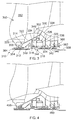
- Figure 4 shows the thrust 456 and radial 460 bearings interchanged between the fore and aft position.
- the fore bearing is the thrust bearing 456, and the aft bearing is the roller bearing 460. Outside of this difference, the two arrangements of Figures 3 and 4 are the same.
- Figure 5 provides an alternative fan shafting arrangement in which the support shaft 518 is provided by the low pressure shaft 558 which passes through the sun gear.
- the intershaft bearing 560 between the low pressure shaft 558 and fan shaft 512 is placed upstream of the gearbox and allows for the differential in rotational speed.
- the support shaft is still independent from the gearbox and so radial forces/excursions in the fan 512 and support shafts 518 are not transferred to the gearbox.
- the low pressure shaft 558 includes the main thrust bearing 562 radially inwards of the low pressure compressor, as with the earlier described embodiments, however, the low pressure shaft 558 now includes an extension which passes fore of the main thrust bearing and through the sun gear 524 along the principle axis of the engine.
- the low pressure shaft 558 still has a dedicated shaft portion for driving the sun gear 524.
- a dual walled or nested low pressure shaft which extends from the main thrust bearing 562 to provide the radial isolation of the fan support shaft and low pressure drive shaft.
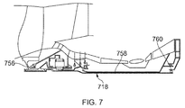
- FIGS. 6 and 7 show yet further alternatives to the fan shafting arrangement in which the fan support shaft 618, 718 extends coaxially within the low pressure shaft 658, 758 to the downstream end thereof.
- the fan shafting arrangement is mechanically isolated from direct contact with the low pressure shaft 658, 758.
- the downstream end of the support shaft 618, 718 is supported by a bearing which appends from a support wall which is attached to the engine casing. The attachment may be downstream of the low pressure turbine.
- the aft support shaft bearing 660 is a roller bearing with the fore bearing being the thrust bearing 656.
- the fore bearing 756 is the roller bearing, with the aft bearing 760 being the thrust bearing.
- reduction gears are in the form of epicyclic gearboxes in which the fan is driven via the carrier of a planetary configuration.
- the reduction gear could be a star configuration in which the planet gears are fixed, or a compound arrangement.
- the described examples above include a low pressure spool having a low pressure turbine, a low pressure shaft and a low pressure compressor. It will be appreciated that the low pressure spool is considered low pressure in relation to the high pressure spool and could be an intermediate pressure spool in some instances. One example of this might be where the fan is taken to be a low pressure compressor in its own right.
Landscapes
- Engineering & Computer Science (AREA)
- Chemical & Material Sciences (AREA)
- Combustion & Propulsion (AREA)
- Mechanical Engineering (AREA)
- General Engineering & Computer Science (AREA)
- Structures Of Non-Positive Displacement Pumps (AREA)
Abstract
Description
- This invention relates to a bearing and shafting arrangement for a gas turbine engine. In particular, the invention relates to a shafting arrangement in a geared turbofan in which a reduction gearbox is used to provide a drive of the propulsive fan.
-
Figure 1 shows a ducted fangas turbine engine 10 comprising in axial flow series: anair intake 12, apropulsive fan 14 having a plurality offan blades 16, anintermediate pressure compressor 18, a high-pressure compressor 20, acombustor 22, a high-pressure turbine 24, anintermediate pressure turbine 26, a low-pressure turbine 28 and acore exhaust nozzle 30. A nacelle (not shown) generally surrounds thefan casing 32 andengine 10 and defines theintake 12, abypass duct 34 and a bypass exhaust nozzle. The engine has a principal axis of rotation 31. - Air entering the
intake 12 is accelerated by thefan 14 to produce a bypass flow and a core flow. The bypass flow travels down thebypass duct 34 and exits the bypass exhaust nozzle 36 to provide the majority of the propulsive thrust produced by theengine 10. The core flow enters in axial flow series theintermediate pressure compressor 18,high pressure compressor 20 and thecombustor 22, where fuel is added to the compressed air and the mixture burnt. The hot combustion products expand through and drive the high, intermediate and low-pressure turbines nozzle 30 to provide additional propulsive thrust. The high, intermediate and low-pressure turbines intermediate pressure compressors fan 14 byconcentric interconnecting shafts - The functional requirements of the fan structure and transmission systems of the fan include amongst others: reacting the fan thrust, radial and couple loads; transmitting the power from the turbine to the fan; and transferring structural loads to the engine casing, nacelle and ultimately airframe.
- The loads from the fan rotor are transmitted to the engine structure by the use of bearings. The bearings and general shafting arrangement are a key component to address the reaction of loads and transmitting of power to the fan from the turbine.
- Typically, the LP system of a direct drive turbofan such as that shown in
Figure 1 consists of fan and turbine rotors connected by a shaft which is supported in the engine structure by a combined bearing support system. The bearing support system usually comprises two or three bearings for the whole LP system. The bearings are typically positioned towards the ends of the respective shaft and optionally at a mid-portion depending on the specific requirements of the engine. - Current trends in gas turbine engines are moving towards so-called geared turbofan engines in which the fan is driven through a reduction gear train. The gear train allows the low pressure spool to be driven at higher rotational speeds which provides for a more efficient lighter engine core, whilst reducing the speed of the fan allows it to be a larger diameter thereby providing a higher bypass ratio. The reduction gear trains may be epicyclic in which the fan is driven via the carrier of a planetary configuration or a star configuration in which the planet gears are fixed, the fan shaft being driven by the ring or star gear. The gear train may be a compound configuration as known in the art.
-
EP1777380 describes a counter rotating fan assembly coupled to the low pressure turbine. The fan assembly includes a first fan assembly which is directly connected to and driven by the low pressure turbine, and a second fan assembly. The second fan assembly is driven through a gearbox to provide the counter rotation. The second fan is also driveably connected to the low pressure compressor or so-called booster compressor. - The introduction of the reduction gearing leads to a more complex bearing support system in which the low pressure spool, gear train and fan all require bearing support.
- The present invention seeks to provide an improved shafting arrangement which allows for improved bearing support.
- The present invention provides a gas turbine engine according to the appended claims.
- A gas turbine engine may comprise: a low pressure spool having a low pressure compressor and a low pressure turbine connected by a low pressure shaft; a reduction gear train having a sun gear, a carrier having a plurality of planet gears attached thereto, and a ring gear, wherein one of the sun gear, carrier or ring gear is connected to the low pressure shaft, and another of the sun gear, carrier and ring gear provides an output drive; a propulsive fan mounted fore of the gear train; a fan shafting arrangement comprising a fan shaft which is connected to the output drive of the gearbox and a fan support shaft which passes through centre of the gearbox along the axis of rotation of the gearbox and fan, wherein the fan shafting arrangement is rotatably supported by at least two axially separated bearings.
- The reduction gear train may be an epicyclic gear box in which the output drive is the carrier, and the input drive is the sun gear.
- The reduction gear ratio of the gear train may be between 2.5:1 and 5:1.
- The fan support shaft may be coaxially nested within the low pressure shaft aft of the gear train.
- The two axially separated bearings may include a fore bearing located forward of the gear train and an aft bearing located aft of the gear train.
- The fan shafting arrangement may further include a drive arm which connects the fan shaft to the carrier and the fore bearing is forward of the drive arm.
- The drive arm may include a fore drive arm and an aft drive arm which are located respectively forward and aft of the gear train, wherein the fore and aft drive arms connect to respective sides of the carrier.
- The gearbox may be enclosed within a housing having upstream and downstream walls, each of the upstream and downstream walls including bearings which engage with and provide rotational support for the fore and aft drive arms respectively.
- The aft bearing may be an intershaft bearing located between the fan support shaft and low pressure shaft.
- The aft bearing may a thrust bearing. The front bearing may be a roller bearing.
- The drive arm may include a coupling portion which includes a section of the shaft wall having a divergent-convergent diametric profile in the downstream direction.
- The support shaft may be formed in part by a portion of the low pressure shaft which passes through the sun gear.
- The support shaft may extend beyond the low pressure shaft in the downstream direction.
- The low pressure shaft and fan shaft may be separated by an intershaft bearing arrangement which is located upstream of the gearbox.
- The low pressure turbine and fan may be co-rotational. The low pressure shaft may terminate with the intershaft bearing such that the low pressure shaft does not extend axially through the support shaft.
- Within the scope of this application it is expressly envisaged that the various aspects, embodiments, examples and alternatives, and in particular the individual features thereof, set out in the preceding paragraphs, in the claims and/or in the following description and drawings, may be taken independently or in any combination where technically compatible, unless otherwise stated.
- Embodiments of the invention will now be described with the aid of the following drawings of which:
-
Figure 1 shows convention gas turbine engine as described above in the background section. -
Figure 2 shows a schematic section of a geared turbo fan arrangement. -
Figure 3 shows a partial section of a geared turbo fan shafting arrangement. -
Figure 4 shows an alternative arrangement of a geared turbo fan shafting arrangement. -
Figure 5 shows a yet further alternative arrangement of a geared turbo fan shafting arrangement. -
Figure 6 shows another alternative arrangement of a geared turbo fan shafting arrangement. -
Figure 7 shows a further alternative arrangement of a geared turbo fan shafting arrangement. -
Figure 2 shows a gearedgas turbine engine 210 having low and high pressure spools, each having respective compressors and turbines driveably interconnected by respective shafts. Thus, there is alow pressure compressor 216 connected to thelow pressure turbine 218 via alow pressure shaft 220, and ahigh pressure compressor 222 connected to ahigh pressure turbine 224 via ahigh pressure shaft 226. The low 216 and high 222 pressure compressors progressively compress air from an inlet downstream of afan 212 to an outlet in flow proximity to thecombustor 228. Compressed air flows from thehigh pressure compressor 222 to thecombustor 228 in which fuel is added to the air and the mixture burnt. The combusted air then expands through the high 224 and low 218 pressure turbines in flow series. The low 220 and high 226 pressure shafts interconnecting the respective turbines and compressors provide the drive for the compressors. - The
fan 212 is foremost so as to be located at the front of theengine 210 and receive air direct from the engine intake, providing it for the inlet of the compressors and the main propulsive flow down thebypass duct 230. Thefan 212 is driveably connected to thelow pressure shaft 220 via agear train 232 in the form of an epicyclic reduction gear box. Thegear train 232 is located between thelow pressure shaft 220 and thefan 212 and is arranged to reduce the speed of thefan 212 relative to the speed of thelow pressure turbine 224. Such an arrangement allows for a higher speed and more efficientlow pressure turbine 218, and slow spinning larger fan which can provide a higher bypass ratio. This freedom allows the speed of the fan and low pressure turbine to be independently optimised. - The
fan 212 has aplurality fan blades 234 extending radially from ahub 236 which is mounted so as to rotate about the principle axis of theengine 210. Thefan 212 resides within afan casing 214 which partially defines thebypass duct 230. Anengine casing 238 surrounds the engine core which comprises the low and high pressure spools andcombustor 228. The engine casing generally provides containment and structural support for the engine core. Theengine casing 238 is ultimately attached to and supported by the wing of the aircraft via an appropriate arrangement ofstruts 240 which extend across thebypass duct 230 and the nacelle which attaches to a pylon as is well known in the art. - The
gear train 232 is in the form of an epicyclic reduction gearbox which is driven in a planetary configuration. Thegear train 232 includes a ring or annular gear which is held substantially stationary in relation to the engine, a planet gear set with individual planets gears interconnected via a carrier, and a sun gear. The sun gear is rotatably connected to the low pressure shaft. The fan is connected to the output shaft of the gearbox which is in the form of the carrier of the planet gear via afan shafting arrangement 242. - The
fan shafting arrangement 242 is rotatable about and in some part defines theprincipal axis 244 of the gearedgas turbine engine 210 and is supported by two axially separated bearings. Thus there is afront bearing 246 provided forward of thegear train 232 with respect to the flow direction of the engine, and asecond bearing 248 positioned aft of thegearbox 232. - As will be seen from the following
Figures 3 to 7 , thefan shafting arrangement 242 typically comprises afan shaft 312 which is independently rotatable from thelow pressure shaft 358 by virtue of an intershaft bearing or by being coupled directly to the engine casing via a direct support which does not include the low pressure shaft. In some embodiments, the shafting arrangement may include a portion of the low pressure shaft as perFigure 5 which is described below. A notable feature of the shafting arrangement is that it has a support shaft which passes through the sun gear of the reduction gear. -
Figure 3 shows a firstfan shafting arrangement 310 in more detail. Theshafting arrangement 310 includes: afan shaft 312; ahub portion 320; afront bearing portion 314 which carries thefront bearing 356 so as to radially support thefan shaft 312 via asupport structure 322; adrive arm 316 which is attached to the carrier of the gear box and provides the drive for the fan, and asupport shaft 318 which extends through the sun gear. - The gear train is an epicyclic reduction gearbox having a
sun gear 324, planet gears 326 which are connected by acarrier 328, and aring gear 330 which is secured to the engine structure via a ringgear support arm 332. The gearbox is held within a housing defined byfore 334 and aft 336 walls which extend radially from theengine casing 338 and terminate inbearings respective fore 344 and aft 346 portions of thedrive arm 316. - The
drive arm 316 extends along and is coaxial with the principal axis of the engine and is generally axi-symmetric. Thedrive arm 316 includes acoupling 348 and a carrier shaft which comprises afore drive arm 344, thecarrier 328 and anaft drive arm 346. It will be appreciated that the so-called aft drive arm does not carry any driving torque and is thus functionally a support shaft rather than a drive shaft per se. - The
coupling 348 extends from a first end, which is attached to the main body of the fan shaft, to thefore drive arm 344. The attachment of the coupling to the fan shaft is dependent on many factors but will generally be placed at the point which minimises the radial deflections of the fan shaft which are transmitted to the gearbox. Thecoupling 348 helps isolate the gearbox from vibration and bending moments experienced by the fan when in use. Thus, the coupling is torsionally rigid but relatively flexible in the radial direction. - The fore 344 and aft 346 drive arms provide a single rotating structure with the
carrier 328 to provide the carrier shaft. The carrier shaft is held in rotative alignment with the principle axis of the engine via thegearbox housing bearings - The
fan 350 is mounted to the hub portion of the shafting arrangement. Thehub portion 320 includes a radially outer body shaped to receive the root end of thefan blades 352 in a conventional manner. Thehub portion 320 is mounted to thefan shaft 312 so as to be rotatably locked and so co-driven therewith about the principal axis of the engine. - The
front bearing portion 354 is in the form of a small stub shaft which is concentrically nested around a shaft of thehub portion 320 and thefan shaft 312 and provides the inner bearing race. Thefront bearing portion 354 provides a platform for receiving the inner race of the front bearing. The platform is in the form of a cylindrical wall which is spaced from and radially outside of the outer surface of thefan shaft 312. - The inner race of the
front bearing 356 is mounted to the outer surface of the front bearing stub shaft towards a distal end thereof. The radially outer race of thefront bearing 356 is supported by afrustoconcical support wall 322 which extends radially outwards and downstream from the bearing race and attaches to the engine casing local to the compressor inlet and first guide vane. Thus, thefront bearing 356 provides radial support for thefan 350 andfan shaft 312 and reacts the load through thefrustoconical wall 322. - In the described embodiment, the
front bearing 356 is a roller bearing having an inner race, an outer race, a plurality of roller elements circumferentially distributed around the stub shaft and retained within a cage, as is known in the art. It will be appreciated that although a roller bearing is described in connection with the arrangement shown inFigure 3 , other bearing types may be used. For example, the front bearing may be a thrust bearing as shown in later Figures. The thrust bearing may be a ball bearing or taper bearing as are known in the art. - In order to provide sufficient structural rigidity to the fan shaft and to allow it to react off-centre loading of the
fan 352, thefan shaft 318 requires two axially separated bearing locations. The axially separated bearings allow bending moments in thefan shaft 312 to be safely reacted to theengine casing 338. In general, it is preferable from a structural loading point of view to place the bearings at certain minimal axial spacings which are dependent on the architecture of the engine and expected loads. Generally, the closer the bearings are, the larger the radial forces are on the bearings and structural supports. Providing a front bearing support upstream of the gearbox and one downstream of the gearbox generally provides for a suitable axial spacing and preferable structural arrangement. Another option would be to place two bearings upstream of the gearbox, however, to provide sufficient spacing the fan would need to be placed further forward which introduces numerous deleterious effects on the engine structural system. - In order to provide fore and aft bearings, the fan shafting arrangement includes a support shaft which passes through the centre of the gearbox. In the example shown, the
support shaft 318 forms part of thefan shaft 312 and lies along the principle axis of the engine. Thesupport shaft 318 passes freely through thesun gear 324 so as to have no direct contact therewith and so can be independently rotated and radially displaced relative to the sun gear and gearbox. Providing the support shaft through the sun gear and in structural isolation from the gearbox allows the radial loading and excursions on thefan shaft 312 to be taken out of the gearbox, vastly simplifying the mechanical requirements of the gearbox. - A first end of the
support shaft 318 is located fore of the gearbox and is attached to a downstream end of thefan shaft 312, aft of the radially extendingdrive arm 316. A second end of thesupport shaft 318 is located on the downstream side of the gear train and terminates in the aft bearing which in the described example is anintershaft bearing arrangement 360. Theintershaft bearing arrangement 360 resides between and allows relative rotation of thelow pressure shaft 358 and thesupport shaft 318 whilst providing radial and axial restraint. The intershaft bearing arrangement includes an inner race, an outer race and a plurality of rolling elements in the form of ball bearings. Hence, the intershaft bearing is a thrust bearing and provides axial restraint of the fan shafting arrangement. - The intershaft bearing end of the support shaft is flared so as to provide a portion of wider diameter in the proximity of the bearing. The internal diameter of the flared portion is sufficient to receive the bearing and the opposing end of the low pressure shaft such that the
bearing arrangement 360 is sandwiched therebetween with thesupport shaft 318 being on the radial outer thereof. Thus, the inner race is attached to thelow pressure shaft 358, and the outer race is attached to thesupport shaft 318. The portion of thelow pressure shaft 358 which supports thesupport shaft 318 terminates with the intershaft bearing. Hence, the low pressure shaft does not proceed axially within or through the support shaft fore of the intershaft bearing. - The
low pressure shaft 358 lies along the principal axis of the engine and provides the driving connection between the low pressure compressor and low pressure turbine. Thelow pressure shaft 358 is radially and axially supported by appropriate bearings along the length thereof. As can be seen inFigure 3 , one of these bearings is athrust bearing 362 located towards the fore end of the shaft. Thethrust bearing 362 provides radial and axial retention of thelow pressure shaft 358 and also provides a stable location for the intershaft bearing 360 which is fore of the low pressure shaft bearing. The main thrust bearing 362 of thelow pressure shaft 358 is attached to the engine casing via a suitable support structure. The outer race of theshafting arrangement intershaft 360 bearing is located immediately upstream of the main thrust bearing 362 on a dedicated flange which extends from the low pressure shaft. Thelow pressure shaft 358 includes a bridge in the form of a flared portion which sits radially outside of and envelops flared end of thesupport shaft 318 before reducing in diameter as it extends towards the attachment point with thesun gear 324. Thus, the support shaft is concentrically nested within the low pressure shaft downstream of thesun gear 324 and rotatably isolated therefrom. - A
catcher shaft 364 is radially nested within thefan shaft 312. Thecatcher shaft 364 comprises a shaft body which may attach to thefan shaft 312 orsupport shaft 318 aft of the drive arm attachment point - The
low pressure shaft 358 is made from two separate sections of shaft which join at the bridge portion, radially outside of theintershaft bearing 360. The joint is provided by a pair of axially opposing radial flanges which are bolted together in an abutting manner. The joint also provides a connection from which a low pressure drive arm extends and attaches to the compressor. - The fore and aft bearings between them provide radial, axial and couple retention of the fan and fan shaft. Thus, one of the bearings is a thrust bearing in the form of a ball bearing, and the other a roller bearing. As will be appreciated by the skilled person, the thrust bearing will provide the axial retention, the roller bearing will provide radial positioning only. Although the example shown in
Figure 3 puts the thrust bearing as the aft bearing, and the roller bearing fore bearing, this need not be the case. Thus,Figure 4 shows thethrust 456 and radial 460 bearings interchanged between the fore and aft position. Hence, the fore bearing is thethrust bearing 456, and the aft bearing is theroller bearing 460. Outside of this difference, the two arrangements ofFigures 3 and 4 are the same. -
Figure 5 provides an alternative fan shafting arrangement in which thesupport shaft 518 is provided by thelow pressure shaft 558 which passes through the sun gear. Here the intershaft bearing 560 between thelow pressure shaft 558 andfan shaft 512 is placed upstream of the gearbox and allows for the differential in rotational speed. The support shaft is still independent from the gearbox and so radial forces/excursions in thefan 512 andsupport shafts 518 are not transferred to the gearbox. Thelow pressure shaft 558 includes the main thrust bearing 562 radially inwards of the low pressure compressor, as with the earlier described embodiments, however, thelow pressure shaft 558 now includes an extension which passes fore of the main thrust bearing and through thesun gear 524 along the principle axis of the engine. - As with the previous examples, the
low pressure shaft 558 still has a dedicated shaft portion for driving thesun gear 524. Hence there is a dual walled or nested low pressure shaft which extends from the main thrust bearing 562 to provide the radial isolation of the fan support shaft and low pressure drive shaft. -
Figures 6 and7 show yet further alternatives to the fan shafting arrangement in which thefan support shaft low pressure shaft low pressure shaft support shaft - In the example of
Figure 6 , the aft support shaft bearing 660 is a roller bearing with the fore bearing being thethrust bearing 656. In the example ofFigure 7 , the fore bearing 756 is the roller bearing, with theaft bearing 760 being the thrust bearing. - The above described reduction gears are in the form of epicyclic gearboxes in which the fan is driven via the carrier of a planetary configuration. However, it will be appreciated that the reduction gear could be a star configuration in which the planet gears are fixed, or a compound arrangement. These different configurations are well known in the art.
- The described examples above include a low pressure spool having a low pressure turbine, a low pressure shaft and a low pressure compressor. It will be appreciated that the low pressure spool is considered low pressure in relation to the high pressure spool and could be an intermediate pressure spool in some instances. One example of this might be where the fan is taken to be a low pressure compressor in its own right.
- It will be understood that the invention is not limited to the described examples and embodiments and various modifications and improvements can be made without departing from the concepts described herein and the scope of the claims. Except where mutually exclusive, any of the features may be employed separately or in combination with any other features and the disclosure extends to and includes all combinations and sub-combinations of one or more described features.
Claims (15)
- A gas turbine engine, comprising:a low pressure spool having a low pressure compressor (216) and a low pressure turbine (218) connected by a low pressure shaft (220);a reduction gear train (232) having a sun gear (324), a carrier (328) having a plurality of planet gears (326) attached thereto, and a ring gear (330), wherein one of the sun gear, carrier or ring gear is connected to the low pressure shaft, and another of the sun gear, carrier and ring gear provides an output drive;a propulsive fan (212) mounted fore of the gear train and at the front of the engine;a fan shafting arrangement (242) comprising a fan shaft (312) which is connected to the output drive of the gear train and a fan support shaft (318) which passes through the centre of the gear train along the axis of rotation of the gearbox and fan, wherein the fan shafting arrangement is rotatably supported by at least two axially separated bearings.
- A gas turbine engine as claimed in claim 1, wherein the reduction gear train is an epicyclic gear box in which the output drive is the carrier, and the input drive is the sun gear and the fan support shaft passes through the centre of the sun gear.
- A gas turbine engine as claimed in claimed either of claims 1 or 2, wherein the fan support shaft is coaxially nested within the low pressure shaft aft of the gear train.
- A gas turbine engine in any preceding claim, wherein the two axially separated bearings include a fore bearing located forward of the gear train and an aft bearing located aft of the gear train.
- A gas turbine engine as claimed in claim 4, wherein the fan shafting arrangement further includes a drive arm which connects the fan shaft to the carrier and the fore bearing is forward of the drive arm.
- A gas turbine engine as claimed in claim 5, wherein the drive arm includes a fore drive arm and an aft drive arm which are located respectively forward and aft of the gear train, wherein the fore and aft drive arms connect to respective sides of the carrier.
- A gas turbine engine as claimed in claim 6, wherein the gearbox is enclosed within a housing having upstream and downstream walls, each of the upstream and downstream walls including bearings which engage with and provide rotational support for the fore and aft drive arms respectively.
- A gas turbine engine as claimed in any of claims 4 to 7, wherein the aft bearing is an intershaft bearing located between the fan support shaft and low pressure shaft.
- A gas turbine engine as claimed in any of claims 4 to 8, wherein the aft bearing is a thrust bearing.
- A gas turbine engine as claimed in any of claims 4 to 8, wherein the front bearing is a roller bearing.
- A gas turbine engine as claimed in any of claims 5 to 10, wherein the drive arm includes a coupling portion which includes a section of the shaft wall having a divergent-convergent diametric profile in the downstream direction.
- A gas turbine as claimed in any preceding claim wherein the support shaft is formed in part by a portion of the low pressure shaft which passes through the sun gear.
- A gas turbine as claimed in any of claims 1 to 11, wherein the support shaft extends beyond the low pressure shaft in the downstream direction.
- A gas turbine as claimed in any of claim 12, wherein the low pressure shaft and fan shaft are separated by an intershaft bearing arrangement which is located upstream of the gearbox.
- A gas turbine as claimed in any preceding claim, wherein the low pressure compressor and low pressure turbine are directly connected by the low pressure shaft so as to rotate at the same speed.
Applications Claiming Priority (1)
| Application Number | Priority Date | Filing Date | Title |
|---|---|---|---|
| GBGB1516570.7A GB201516570D0 (en) | 2015-09-18 | 2015-09-18 | A Shafting Arrangement |
Publications (2)
| Publication Number | Publication Date |
|---|---|
| EP3144486A1 true EP3144486A1 (en) | 2017-03-22 |
| EP3144486B1 EP3144486B1 (en) | 2020-03-18 |
Family
ID=54544464
Family Applications (1)
| Application Number | Title | Priority Date | Filing Date |
|---|---|---|---|
| EP16188333.5A Active EP3144486B1 (en) | 2015-09-18 | 2016-09-12 | A shafting arrangement for a gas turbine engine |
Country Status (3)
| Country | Link |
|---|---|
| US (1) | US10393068B2 (en) |
| EP (1) | EP3144486B1 (en) |
| GB (1) | GB201516570D0 (en) |
Cited By (5)
| Publication number | Priority date | Publication date | Assignee | Title |
|---|---|---|---|---|
| EP3587768A1 (en) | 2018-06-27 | 2020-01-01 | Rolls-Royce Deutschland Ltd & Co KG | Gas turbine |
| EP3587773A1 (en) | 2018-06-27 | 2020-01-01 | Rolls-Royce plc | Gas turbine |
| EP3587764A1 (en) | 2018-06-27 | 2020-01-01 | Rolls-Royce Deutschland Ltd & Co KG | Gas turbine |
| EP3825532A1 (en) * | 2019-11-20 | 2021-05-26 | Raytheon Technologies Corporation | Geared architecture for gas turbine engine |
| EP3825533A1 (en) * | 2019-11-20 | 2021-05-26 | Raytheon Technologies Corporation | Geared architecture for gas turbine engine |
Families Citing this family (13)
| Publication number | Priority date | Publication date | Assignee | Title |
|---|---|---|---|---|
| GB201613029D0 (en) * | 2016-07-28 | 2016-09-14 | Rolls Royce Plc | A sun gear drive arrangement |
| EP3296525B1 (en) | 2016-09-20 | 2019-11-27 | Rolls-Royce Deutschland Ltd & Co KG | Gas turbine engine with a geared turbofan arrangement |
| EP3296540B1 (en) | 2016-09-20 | 2019-01-23 | Rolls-Royce Deutschland Ltd & Co KG | Gas turbine engine with a geared turbofan arrangement |
| EP3296524B1 (en) | 2016-09-20 | 2019-02-27 | Rolls-Royce Deutschland Ltd & Co KG | Gas turbine engine with a geared turbofan arrangement |
| EP3296552B1 (en) | 2016-09-20 | 2019-06-05 | Rolls-Royce Deutschland Ltd & Co KG | Gas turbine engine with a geared turbofan arrangement |
| US10954813B2 (en) * | 2017-08-18 | 2021-03-23 | Rolls-Royce Deutschland Ltd & Co Kg | Planetary gearbox system and method for operating a planetary gearbox system |
| EP3444495A1 (en) | 2017-08-18 | 2019-02-20 | Rolls-Royce Deutschland Ltd & Co KG | Mechanical clutch device and method for operating a mechanical clutch device |
| GB201720391D0 (en) * | 2017-12-07 | 2018-01-24 | Rolls Royce Plc | A gas turbine engine |
| US10590993B1 (en) | 2018-08-31 | 2020-03-17 | Rolls-Royce North American Technologies Inc. | Bearing race cooling |
| US11054039B2 (en) | 2018-08-31 | 2021-07-06 | Rolls-Royce Corporation | Seal runner support |
| GB201900382D0 (en) * | 2019-01-11 | 2019-02-27 | Rolls Royce Plc | Gas turbine engine |
| GB201913195D0 (en) * | 2019-09-12 | 2019-10-30 | Rolls Royce Plc | Gas turbine engine |
| US11492932B2 (en) * | 2020-08-13 | 2022-11-08 | Raytheon Technologies Corporation | Deflection limiter for a gas turbine engine |
Citations (5)
| Publication number | Priority date | Publication date | Assignee | Title |
|---|---|---|---|---|
| GB878934A (en) * | 1959-08-13 | 1961-10-04 | Rolls Royce | Improvements in gas turbine jet propulsion engines |
| US6622473B2 (en) * | 2000-12-07 | 2003-09-23 | Hispano-Suiza | Speed-reducing gear unit to absorb the axial loads generated by a turbojet fan |
| EP1649191A1 (en) * | 2003-07-29 | 2006-04-26 | Pratt & Whitney Canada Corp. | Compact epicyclic gear carrier |
| EP1777380A2 (en) * | 2005-10-19 | 2007-04-25 | General Electric Company | Gas turbine engine assembly and methods of assembling same |
| EP2360391A1 (en) * | 2010-02-23 | 2011-08-24 | General Electric Company | Epicyclic Gearbox |
Family Cites Families (13)
| Publication number | Priority date | Publication date | Assignee | Title |
|---|---|---|---|---|
| GB1484948A (en) | 1975-09-04 | 1977-09-08 | Rolls Royce | Ducted fan gas turbine engine |
| US4916894A (en) * | 1989-01-03 | 1990-04-17 | General Electric Company | High bypass turbofan engine having a partially geared fan drive turbine |
| US4969325A (en) * | 1989-01-03 | 1990-11-13 | General Electric Company | Turbofan engine having a counterrotating partially geared fan drive turbine |
| US7603844B2 (en) * | 2005-10-19 | 2009-10-20 | General Electric Company | Gas turbine engine assembly and methods of assembling same |
| US7490460B2 (en) * | 2005-10-19 | 2009-02-17 | General Electric Company | Gas turbine engine assembly and methods of assembling same |
| US7490461B2 (en) * | 2005-10-19 | 2009-02-17 | General Electric Company | Gas turbine engine assembly and methods of assembling same |
| US7493753B2 (en) * | 2005-10-19 | 2009-02-24 | General Electric Company | Gas turbine engine assembly and methods of assembling same |
| US7685808B2 (en) * | 2005-10-19 | 2010-03-30 | General Electric Company | Gas turbine engine assembly and methods of assembling same |
| FR2942273B1 (en) * | 2009-02-18 | 2011-06-10 | Snecma | DOUBLE FLOW MOTOR WITH CONTRAROTATIVE TURBINE WHEELS |
| FR2943035B1 (en) | 2009-03-11 | 2012-09-28 | Snecma | DEVICE FOR DRIVING A PAIRE OF CONTRAROTIVE PROPELLERS BY AN EPYCYCLOIDAL TRAIN |
| US8777793B2 (en) | 2011-04-27 | 2014-07-15 | United Technologies Corporation | Fan drive planetary gear system integrated carrier and torque frame |
| US9926850B2 (en) | 2013-02-11 | 2018-03-27 | United Technologies Corporation | Compound star gear system with rolling element bearings |
| GB201516571D0 (en) * | 2015-09-18 | 2015-11-04 | Rolls Royce Plc | A Coupling for a Geared Turbo Fan |
-
2015
- 2015-09-18 GB GBGB1516570.7A patent/GB201516570D0/en not_active Ceased
-
2016
- 2016-09-12 US US15/262,612 patent/US10393068B2/en active Active
- 2016-09-12 EP EP16188333.5A patent/EP3144486B1/en active Active
Patent Citations (5)
| Publication number | Priority date | Publication date | Assignee | Title |
|---|---|---|---|---|
| GB878934A (en) * | 1959-08-13 | 1961-10-04 | Rolls Royce | Improvements in gas turbine jet propulsion engines |
| US6622473B2 (en) * | 2000-12-07 | 2003-09-23 | Hispano-Suiza | Speed-reducing gear unit to absorb the axial loads generated by a turbojet fan |
| EP1649191A1 (en) * | 2003-07-29 | 2006-04-26 | Pratt & Whitney Canada Corp. | Compact epicyclic gear carrier |
| EP1777380A2 (en) * | 2005-10-19 | 2007-04-25 | General Electric Company | Gas turbine engine assembly and methods of assembling same |
| EP2360391A1 (en) * | 2010-02-23 | 2011-08-24 | General Electric Company | Epicyclic Gearbox |
Cited By (17)
| Publication number | Priority date | Publication date | Assignee | Title |
|---|---|---|---|---|
| US10920672B2 (en) | 2018-06-27 | 2021-02-16 | Rolls-Royce Plc | Gas turbine |
| EP3587764A1 (en) | 2018-06-27 | 2020-01-01 | Rolls-Royce Deutschland Ltd & Co KG | Gas turbine |
| EP3587768A1 (en) | 2018-06-27 | 2020-01-01 | Rolls-Royce Deutschland Ltd & Co KG | Gas turbine |
| EP3587772A1 (en) | 2018-06-27 | 2020-01-01 | Rolls-Royce plc | Gas turbine |
| CN110645095B (en) * | 2018-06-27 | 2024-03-01 | 劳斯莱斯有限公司 | Gas turbine |
| CN110645095A (en) * | 2018-06-27 | 2020-01-03 | 劳斯莱斯有限公司 | Gas turbine |
| CN110645094A (en) * | 2018-06-27 | 2020-01-03 | 劳斯莱斯有限公司 | Gas turbine |
| US11454174B2 (en) | 2018-06-27 | 2022-09-27 | Rolls-Royce Plc | Gas turbine |
| EP3587774A1 (en) | 2018-06-27 | 2020-01-01 | Rolls-Royce plc | Gas turbine |
| EP3587773A1 (en) | 2018-06-27 | 2020-01-01 | Rolls-Royce plc | Gas turbine |
| US10914240B2 (en) | 2018-06-27 | 2021-02-09 | Rolls-Royce Plc | Gas turbine |
| US11131209B2 (en) | 2018-06-27 | 2021-09-28 | Rolls-Royce Deutschland Ltd & Co Kg | Gas turbine |
| US11187157B2 (en) | 2018-06-27 | 2021-11-30 | Rolls-Royce Plc | Gas turbine |
| US11162575B2 (en) | 2019-11-20 | 2021-11-02 | Raytheon Technologies Corporation | Geared architecture for gas turbine engine |
| US11415064B2 (en) | 2019-11-20 | 2022-08-16 | Raytheon Technologies Corporation | Geared architecture for gas turbine engine |
| EP3825533A1 (en) * | 2019-11-20 | 2021-05-26 | Raytheon Technologies Corporation | Geared architecture for gas turbine engine |
| EP3825532A1 (en) * | 2019-11-20 | 2021-05-26 | Raytheon Technologies Corporation | Geared architecture for gas turbine engine |
Also Published As
| Publication number | Publication date |
|---|---|
| US10393068B2 (en) | 2019-08-27 |
| GB201516570D0 (en) | 2015-11-04 |
| US20170082065A1 (en) | 2017-03-23 |
| EP3144486B1 (en) | 2020-03-18 |
Similar Documents
| Publication | Publication Date | Title |
|---|---|---|
| US10393068B2 (en) | Shafting arrangement for a gas turbine engine | |
| EP3144487B1 (en) | A coupling for a geared turbo fan | |
| US10519871B2 (en) | Support assembly for a propeller shaft | |
| US10294872B2 (en) | Sun gear drive arrangement | |
| US10590854B2 (en) | Geared gas turbine engine | |
| CA2928979C (en) | System for supporting rotor shafts of an indirect drive turbofan engine | |
| EP3597884B1 (en) | A multi-spool gas turbine engine architecture | |
| US11187157B2 (en) | Gas turbine | |
| US8956108B2 (en) | Geared fan assembly | |
| EP3431714B1 (en) | Air inlet for a gas turbine engine | |
| US10746188B2 (en) | Inter-shaft bearing connected to a compressor boost system | |
| US11268440B2 (en) | Stabilization bearing system for geared turbofan engines | |
| US20200056507A1 (en) | Device for coupling an output shaft with an epicyclic gearbox, method for coupling an output shaft with an epicyclic gearbox and a gas turbine engine | |
| US10023320B2 (en) | Propulsion unit with a pair of propellers for an aircraft | |
| US10502144B2 (en) | Gas turbine engine with a geared turbofan arrangement | |
| US11852080B1 (en) | Gearbox assembly | |
| CA2991968A1 (en) | Inter-shaft bearing connected to a compressor boost system | |
| CN115698483A (en) | Aircraft turbine |
Legal Events
| Date | Code | Title | Description |
|---|---|---|---|
| PUAI | Public reference made under article 153(3) epc to a published international application that has entered the european phase |
Free format text: ORIGINAL CODE: 0009012 |
|
| STAA | Information on the status of an ep patent application or granted ep patent |
Free format text: STATUS: THE APPLICATION HAS BEEN PUBLISHED |
|
| AK | Designated contracting states |
Kind code of ref document: A1 Designated state(s): AL AT BE BG CH CY CZ DE DK EE ES FI FR GB GR HR HU IE IS IT LI LT LU LV MC MK MT NL NO PL PT RO RS SE SI SK SM TR |
|
| AX | Request for extension of the european patent |
Extension state: BA ME |
|
| STAA | Information on the status of an ep patent application or granted ep patent |
Free format text: STATUS: REQUEST FOR EXAMINATION WAS MADE |
|
| 17P | Request for examination filed |
Effective date: 20170919 |
|
| RBV | Designated contracting states (corrected) |
Designated state(s): AL AT BE BG CH CY CZ DE DK EE ES FI FR GB GR HR HU IE IS IT LI LT LU LV MC MK MT NL NO PL PT RO RS SE SI SK SM TR |
|
| STAA | Information on the status of an ep patent application or granted ep patent |
Free format text: STATUS: EXAMINATION IS IN PROGRESS |
|
| 17Q | First examination report despatched |
Effective date: 20180830 |
|
| GRAP | Despatch of communication of intention to grant a patent |
Free format text: ORIGINAL CODE: EPIDOSNIGR1 |
|
| STAA | Information on the status of an ep patent application or granted ep patent |
Free format text: STATUS: GRANT OF PATENT IS INTENDED |
|
| GRAS | Grant fee paid |
Free format text: ORIGINAL CODE: EPIDOSNIGR3 |
|
| GRAA | (expected) grant |
Free format text: ORIGINAL CODE: 0009210 |
|
| STAA | Information on the status of an ep patent application or granted ep patent |
Free format text: STATUS: THE PATENT HAS BEEN GRANTED |
|
| INTG | Intention to grant announced |
Effective date: 20200127 |
|
| RAP1 | Party data changed (applicant data changed or rights of an application transferred) |
Owner name: ROLLS-ROYCE PLC |
|
| AK | Designated contracting states |
Kind code of ref document: B1 Designated state(s): AL AT BE BG CH CY CZ DE DK EE ES FI FR GB GR HR HU IE IS IT LI LT LU LV MC MK MT NL NO PL PT RO RS SE SI SK SM TR |
|
| REG | Reference to a national code |
Ref country code: GB Ref legal event code: FG4D |
|
| REG | Reference to a national code |
Ref country code: DE Ref legal event code: R096 Ref document number: 602016031886 Country of ref document: DE |
|
| REG | Reference to a national code |
Ref country code: AT Ref legal event code: REF Ref document number: 1246131 Country of ref document: AT Kind code of ref document: T Effective date: 20200415 Ref country code: IE Ref legal event code: FG4D |
|
| PG25 | Lapsed in a contracting state [announced via postgrant information from national office to epo] |
Ref country code: NO Free format text: LAPSE BECAUSE OF FAILURE TO SUBMIT A TRANSLATION OF THE DESCRIPTION OR TO PAY THE FEE WITHIN THE PRESCRIBED TIME-LIMIT Effective date: 20200618 Ref country code: RS Free format text: LAPSE BECAUSE OF FAILURE TO SUBMIT A TRANSLATION OF THE DESCRIPTION OR TO PAY THE FEE WITHIN THE PRESCRIBED TIME-LIMIT Effective date: 20200318 Ref country code: FI Free format text: LAPSE BECAUSE OF FAILURE TO SUBMIT A TRANSLATION OF THE DESCRIPTION OR TO PAY THE FEE WITHIN THE PRESCRIBED TIME-LIMIT Effective date: 20200318 |
|
| REG | Reference to a national code |
Ref country code: NL Ref legal event code: MP Effective date: 20200318 |
|
| PG25 | Lapsed in a contracting state [announced via postgrant information from national office to epo] |
Ref country code: BG Free format text: LAPSE BECAUSE OF FAILURE TO SUBMIT A TRANSLATION OF THE DESCRIPTION OR TO PAY THE FEE WITHIN THE PRESCRIBED TIME-LIMIT Effective date: 20200618 Ref country code: GR Free format text: LAPSE BECAUSE OF FAILURE TO SUBMIT A TRANSLATION OF THE DESCRIPTION OR TO PAY THE FEE WITHIN THE PRESCRIBED TIME-LIMIT Effective date: 20200619 Ref country code: SE Free format text: LAPSE BECAUSE OF FAILURE TO SUBMIT A TRANSLATION OF THE DESCRIPTION OR TO PAY THE FEE WITHIN THE PRESCRIBED TIME-LIMIT Effective date: 20200318 Ref country code: LV Free format text: LAPSE BECAUSE OF FAILURE TO SUBMIT A TRANSLATION OF THE DESCRIPTION OR TO PAY THE FEE WITHIN THE PRESCRIBED TIME-LIMIT Effective date: 20200318 Ref country code: HR Free format text: LAPSE BECAUSE OF FAILURE TO SUBMIT A TRANSLATION OF THE DESCRIPTION OR TO PAY THE FEE WITHIN THE PRESCRIBED TIME-LIMIT Effective date: 20200318 |
|
| REG | Reference to a national code |
Ref country code: LT Ref legal event code: MG4D |
|
| PG25 | Lapsed in a contracting state [announced via postgrant information from national office to epo] |
Ref country code: NL Free format text: LAPSE BECAUSE OF FAILURE TO SUBMIT A TRANSLATION OF THE DESCRIPTION OR TO PAY THE FEE WITHIN THE PRESCRIBED TIME-LIMIT Effective date: 20200318 |
|
| PG25 | Lapsed in a contracting state [announced via postgrant information from national office to epo] |
Ref country code: IS Free format text: LAPSE BECAUSE OF FAILURE TO SUBMIT A TRANSLATION OF THE DESCRIPTION OR TO PAY THE FEE WITHIN THE PRESCRIBED TIME-LIMIT Effective date: 20200718 Ref country code: SK Free format text: LAPSE BECAUSE OF FAILURE TO SUBMIT A TRANSLATION OF THE DESCRIPTION OR TO PAY THE FEE WITHIN THE PRESCRIBED TIME-LIMIT Effective date: 20200318 Ref country code: RO Free format text: LAPSE BECAUSE OF FAILURE TO SUBMIT A TRANSLATION OF THE DESCRIPTION OR TO PAY THE FEE WITHIN THE PRESCRIBED TIME-LIMIT Effective date: 20200318 Ref country code: LT Free format text: LAPSE BECAUSE OF FAILURE TO SUBMIT A TRANSLATION OF THE DESCRIPTION OR TO PAY THE FEE WITHIN THE PRESCRIBED TIME-LIMIT Effective date: 20200318 Ref country code: CZ Free format text: LAPSE BECAUSE OF FAILURE TO SUBMIT A TRANSLATION OF THE DESCRIPTION OR TO PAY THE FEE WITHIN THE PRESCRIBED TIME-LIMIT Effective date: 20200318 Ref country code: PT Free format text: LAPSE BECAUSE OF FAILURE TO SUBMIT A TRANSLATION OF THE DESCRIPTION OR TO PAY THE FEE WITHIN THE PRESCRIBED TIME-LIMIT Effective date: 20200812 Ref country code: EE Free format text: LAPSE BECAUSE OF FAILURE TO SUBMIT A TRANSLATION OF THE DESCRIPTION OR TO PAY THE FEE WITHIN THE PRESCRIBED TIME-LIMIT Effective date: 20200318 Ref country code: SM Free format text: LAPSE BECAUSE OF FAILURE TO SUBMIT A TRANSLATION OF THE DESCRIPTION OR TO PAY THE FEE WITHIN THE PRESCRIBED TIME-LIMIT Effective date: 20200318 |
|
| REG | Reference to a national code |
Ref country code: AT Ref legal event code: MK05 Ref document number: 1246131 Country of ref document: AT Kind code of ref document: T Effective date: 20200318 |
|
| REG | Reference to a national code |
Ref country code: DE Ref legal event code: R097 Ref document number: 602016031886 Country of ref document: DE |
|
| PLBE | No opposition filed within time limit |
Free format text: ORIGINAL CODE: 0009261 |
|
| STAA | Information on the status of an ep patent application or granted ep patent |
Free format text: STATUS: NO OPPOSITION FILED WITHIN TIME LIMIT |
|
| PG25 | Lapsed in a contracting state [announced via postgrant information from national office to epo] |
Ref country code: ES Free format text: LAPSE BECAUSE OF FAILURE TO SUBMIT A TRANSLATION OF THE DESCRIPTION OR TO PAY THE FEE WITHIN THE PRESCRIBED TIME-LIMIT Effective date: 20200318 Ref country code: DK Free format text: LAPSE BECAUSE OF FAILURE TO SUBMIT A TRANSLATION OF THE DESCRIPTION OR TO PAY THE FEE WITHIN THE PRESCRIBED TIME-LIMIT Effective date: 20200318 Ref country code: AT Free format text: LAPSE BECAUSE OF FAILURE TO SUBMIT A TRANSLATION OF THE DESCRIPTION OR TO PAY THE FEE WITHIN THE PRESCRIBED TIME-LIMIT Effective date: 20200318 |
|
| 26N | No opposition filed |
Effective date: 20201221 |
|
| PG25 | Lapsed in a contracting state [announced via postgrant information from national office to epo] |
Ref country code: PL Free format text: LAPSE BECAUSE OF FAILURE TO SUBMIT A TRANSLATION OF THE DESCRIPTION OR TO PAY THE FEE WITHIN THE PRESCRIBED TIME-LIMIT Effective date: 20200318 |
|
| PG25 | Lapsed in a contracting state [announced via postgrant information from national office to epo] |
Ref country code: MC Free format text: LAPSE BECAUSE OF FAILURE TO SUBMIT A TRANSLATION OF THE DESCRIPTION OR TO PAY THE FEE WITHIN THE PRESCRIBED TIME-LIMIT Effective date: 20200318 |
|
| REG | Reference to a national code |
Ref country code: CH Ref legal event code: PL |
|
| PG25 | Lapsed in a contracting state [announced via postgrant information from national office to epo] |
Ref country code: SI Free format text: LAPSE BECAUSE OF FAILURE TO SUBMIT A TRANSLATION OF THE DESCRIPTION OR TO PAY THE FEE WITHIN THE PRESCRIBED TIME-LIMIT Effective date: 20200318 |
|
| REG | Reference to a national code |
Ref country code: BE Ref legal event code: MM Effective date: 20200930 |
|
| PG25 | Lapsed in a contracting state [announced via postgrant information from national office to epo] |
Ref country code: LU Free format text: LAPSE BECAUSE OF NON-PAYMENT OF DUE FEES Effective date: 20200912 |
|
| PG25 | Lapsed in a contracting state [announced via postgrant information from national office to epo] |
Ref country code: LI Free format text: LAPSE BECAUSE OF NON-PAYMENT OF DUE FEES Effective date: 20200930 Ref country code: IE Free format text: LAPSE BECAUSE OF NON-PAYMENT OF DUE FEES Effective date: 20200912 Ref country code: BE Free format text: LAPSE BECAUSE OF NON-PAYMENT OF DUE FEES Effective date: 20200930 Ref country code: CH Free format text: LAPSE BECAUSE OF NON-PAYMENT OF DUE FEES Effective date: 20200930 |
|
| PG25 | Lapsed in a contracting state [announced via postgrant information from national office to epo] |
Ref country code: TR Free format text: LAPSE BECAUSE OF FAILURE TO SUBMIT A TRANSLATION OF THE DESCRIPTION OR TO PAY THE FEE WITHIN THE PRESCRIBED TIME-LIMIT Effective date: 20200318 Ref country code: MT Free format text: LAPSE BECAUSE OF FAILURE TO SUBMIT A TRANSLATION OF THE DESCRIPTION OR TO PAY THE FEE WITHIN THE PRESCRIBED TIME-LIMIT Effective date: 20200318 Ref country code: CY Free format text: LAPSE BECAUSE OF FAILURE TO SUBMIT A TRANSLATION OF THE DESCRIPTION OR TO PAY THE FEE WITHIN THE PRESCRIBED TIME-LIMIT Effective date: 20200318 |
|
| PG25 | Lapsed in a contracting state [announced via postgrant information from national office to epo] |
Ref country code: MK Free format text: LAPSE BECAUSE OF FAILURE TO SUBMIT A TRANSLATION OF THE DESCRIPTION OR TO PAY THE FEE WITHIN THE PRESCRIBED TIME-LIMIT Effective date: 20200318 Ref country code: AL Free format text: LAPSE BECAUSE OF FAILURE TO SUBMIT A TRANSLATION OF THE DESCRIPTION OR TO PAY THE FEE WITHIN THE PRESCRIBED TIME-LIMIT Effective date: 20200318 |
|
| P01 | Opt-out of the competence of the unified patent court (upc) registered |
Effective date: 20230528 |
|
| PGFP | Annual fee paid to national office [announced via postgrant information from national office to epo] |
Ref country code: IT Payment date: 20230920 Year of fee payment: 8 Ref country code: GB Payment date: 20230926 Year of fee payment: 8 |
|
| PGFP | Annual fee paid to national office [announced via postgrant information from national office to epo] |
Ref country code: FR Payment date: 20230926 Year of fee payment: 8 Ref country code: DE Payment date: 20230928 Year of fee payment: 8 |