EP2360391A1 - Epicyclic Gearbox - Google Patents
Epicyclic Gearbox Download PDFInfo
- Publication number
- EP2360391A1 EP2360391A1 EP11155563A EP11155563A EP2360391A1 EP 2360391 A1 EP2360391 A1 EP 2360391A1 EP 11155563 A EP11155563 A EP 11155563A EP 11155563 A EP11155563 A EP 11155563A EP 2360391 A1 EP2360391 A1 EP 2360391A1
- Authority
- EP
- European Patent Office
- Prior art keywords
- aft
- gear
- output teeth
- planetary gears
- spindles
- Prior art date
- Legal status (The legal status is an assumption and is not a legal conclusion. Google has not performed a legal analysis and makes no representation as to the accuracy of the status listed.)
- Granted
Links
- 239000007789 gas Substances 0.000 description 19
- 239000003570 air Substances 0.000 description 3
- 239000000446 fuel Substances 0.000 description 3
- 239000000567 combustion gas Substances 0.000 description 2
- 238000012986 modification Methods 0.000 description 2
- 230000004048 modification Effects 0.000 description 2
- 239000012080 ambient air Substances 0.000 description 1
- 238000006243 chemical reaction Methods 0.000 description 1
- 230000000694 effects Effects 0.000 description 1
- 230000020169 heat generation Effects 0.000 description 1
- 230000013011 mating Effects 0.000 description 1
Images

Classifications
-
- F—MECHANICAL ENGINEERING; LIGHTING; HEATING; WEAPONS; BLASTING
- F16—ENGINEERING ELEMENTS AND UNITS; GENERAL MEASURES FOR PRODUCING AND MAINTAINING EFFECTIVE FUNCTIONING OF MACHINES OR INSTALLATIONS; THERMAL INSULATION IN GENERAL
- F16H—GEARING
- F16H1/00—Toothed gearings for conveying rotary motion
- F16H1/28—Toothed gearings for conveying rotary motion with gears having orbital motion
-
- F—MECHANICAL ENGINEERING; LIGHTING; HEATING; WEAPONS; BLASTING
- F02—COMBUSTION ENGINES; HOT-GAS OR COMBUSTION-PRODUCT ENGINE PLANTS
- F02C—GAS-TURBINE PLANTS; AIR INTAKES FOR JET-PROPULSION PLANTS; CONTROLLING FUEL SUPPLY IN AIR-BREATHING JET-PROPULSION PLANTS
- F02C3/00—Gas-turbine plants characterised by the use of combustion products as the working fluid
- F02C3/04—Gas-turbine plants characterised by the use of combustion products as the working fluid having a turbine driving a compressor
- F02C3/107—Gas-turbine plants characterised by the use of combustion products as the working fluid having a turbine driving a compressor with two or more rotors connected by power transmission
-
- F—MECHANICAL ENGINEERING; LIGHTING; HEATING; WEAPONS; BLASTING
- F02—COMBUSTION ENGINES; HOT-GAS OR COMBUSTION-PRODUCT ENGINE PLANTS
- F02K—JET-PROPULSION PLANTS
- F02K3/00—Plants including a gas turbine driving a compressor or a ducted fan
- F02K3/02—Plants including a gas turbine driving a compressor or a ducted fan in which part of the working fluid by-passes the turbine and combustion chamber
- F02K3/04—Plants including a gas turbine driving a compressor or a ducted fan in which part of the working fluid by-passes the turbine and combustion chamber the plant including ducted fans, i.e. fans with high volume, low pressure outputs, for augmenting the jet thrust, e.g. of double-flow type
- F02K3/06—Plants including a gas turbine driving a compressor or a ducted fan in which part of the working fluid by-passes the turbine and combustion chamber the plant including ducted fans, i.e. fans with high volume, low pressure outputs, for augmenting the jet thrust, e.g. of double-flow type with front fan
-
- F—MECHANICAL ENGINEERING; LIGHTING; HEATING; WEAPONS; BLASTING
- F16—ENGINEERING ELEMENTS AND UNITS; GENERAL MEASURES FOR PRODUCING AND MAINTAINING EFFECTIVE FUNCTIONING OF MACHINES OR INSTALLATIONS; THERMAL INSULATION IN GENERAL
- F16H—GEARING
- F16H57/00—General details of gearing
- F16H57/08—General details of gearing of gearings with members having orbital motion
- F16H57/082—Planet carriers
-
- F—MECHANICAL ENGINEERING; LIGHTING; HEATING; WEAPONS; BLASTING
- F05—INDEXING SCHEMES RELATING TO ENGINES OR PUMPS IN VARIOUS SUBCLASSES OF CLASSES F01-F04
- F05D—INDEXING SCHEME FOR ASPECTS RELATING TO NON-POSITIVE-DISPLACEMENT MACHINES OR ENGINES, GAS-TURBINES OR JET-PROPULSION PLANTS
- F05D2260/00—Function
- F05D2260/40—Transmission of power
- F05D2260/403—Transmission of power through the shape of the drive components
- F05D2260/4031—Transmission of power through the shape of the drive components as in toothed gearing
- F05D2260/40311—Transmission of power through the shape of the drive components as in toothed gearing of the epicyclical, planetary or differential type
-
- F—MECHANICAL ENGINEERING; LIGHTING; HEATING; WEAPONS; BLASTING
- F16—ENGINEERING ELEMENTS AND UNITS; GENERAL MEASURES FOR PRODUCING AND MAINTAINING EFFECTIVE FUNCTIONING OF MACHINES OR INSTALLATIONS; THERMAL INSULATION IN GENERAL
- F16H—GEARING
- F16H1/00—Toothed gearings for conveying rotary motion
- F16H1/28—Toothed gearings for conveying rotary motion with gears having orbital motion
- F16H2001/2881—Toothed gearings for conveying rotary motion with gears having orbital motion comprising two axially spaced central gears, i.e. ring or sun gear, engaged by at least one common orbital gear wherein one of the central gears is forming the output
-
- Y—GENERAL TAGGING OF NEW TECHNOLOGICAL DEVELOPMENTS; GENERAL TAGGING OF CROSS-SECTIONAL TECHNOLOGIES SPANNING OVER SEVERAL SECTIONS OF THE IPC; TECHNICAL SUBJECTS COVERED BY FORMER USPC CROSS-REFERENCE ART COLLECTIONS [XRACs] AND DIGESTS
- Y02—TECHNOLOGIES OR APPLICATIONS FOR MITIGATION OR ADAPTATION AGAINST CLIMATE CHANGE
- Y02T—CLIMATE CHANGE MITIGATION TECHNOLOGIES RELATED TO TRANSPORTATION
- Y02T50/00—Aeronautics or air transport
- Y02T50/60—Efficient propulsion technologies, e.g. for aircraft
Definitions
- the invention relates to epicyclic gearboxes with particular application to aircraft gas turbine engines with counter-rotatable fans.
- An aircraft gas turbine engine of the turbofan type generally includes a forward fan and booster compressor, a middle core engine, and an aft low pressure power turbine.
- the core engine includes a high pressure compressor, a combustor, and a high pressure turbine in a serial flow relationship.
- the high pressure compressor and high pressure turbine of the core engine are interconnected by a high pressure shaft.
- the high pressure compressor, turbine, and shaft essentially form the high pressure rotor or spool.
- the high pressure compressor is rotatably driven to compress air entering the core engine to a relatively high pressure. This high pressure air is then mixed with fuel in the combustor and ignited to form a high energy gas stream.
- the gas stream flows aft and passes through the high pressure turbine, rotatably driving it and the high pressure shaft which, in turn, rotatably drives the compressor.
- the gas stream leaving the high pressure turbine is expanded through a second or low pressure turbine.
- the low pressure turbine rotatably drives the fan and booster compressor via a low pressure shaft, all of which form the low pressure rotor or spool.
- the low pressure shaft extends through the high pressure rotor.
- Size, weight, and reliability of an epicyclic gearbox depends a great deal on planet bearing loads, life requirements, and gear tooth stresses. It is highly desirable to significantly reduce the planet bearing loads of a counter-rotating epicyclic gearbox in order to increase gearbox reliability. It is also highly desirable to reduced loads enabling the use of smaller bearings which reduces weight and improves life of the gearbox. Smaller bearings also decrease the heat generation of the gearbox which results in an efficiency improvement and reduced oil flow requirements.
- An epicyclic gear train includes planetary gears rotatably mounted on spindles supported by an annular carrier.
- Each of the planetary gears includes axially spaced apart forward and aft sets of output teeth extending radially outwardly from a hollow planetary gear hub.
- Axially spaced apart forward and aft roller bearings are disposed between the planetary gears and the spindles.
- An exemplary embodiment of the epicyclic gear train further includes the forward and aft roller bearings being axially aligned with or adjacent to the spaced apart forward and aft sets of output teeth.
- An input gear is fixedly attached to the planetary gear hub aft of the aft set of output teeth of each of the each of the planetary gears.
- the forward roller bearing is axially aligned with the forward set of output teeth and the aft roller bearing is axially adjacent to the input gear.
- the exemplary embodiment of the epicyclic gear train further includes a ring gear circumscribing and engaging the forward set of output teeth and an external gear meshing with the aft set of output teeth.
- the input gear meshes with a sun gear.
- the forward set of output teeth meshes with the ring gear radially outwardly of the spindles and the aft set of output teeth meshes with the external gear radially outwardly of the spindles.
- the input gear of each of the planetary gears meshes with the sun gear radially inwardly of the spindles.
- the forward and aft set of output teeth, the input gear of the planetary gears, the ring gear, the external gear, and the sun gear may be helical.
- the epicyclic gear train may be used in an epicyclic gearbox further including the spindles supported by forward and aft conical carrier frames of the annular carrier.
- the forward and aft conical carrier frames include radially outer forward and aft carrier flanges respectively, radially inner forward and aft support flanges respectively fixedly supporting the spindles therebetween and connected by conical forward and aft support beams to the forward and aft carrier flanges.
- a turbofan gas turbine engine may incorporate the epicyclic gearbox to counter rotatably drive counter-rotatable first and second fan stages radially supported, at least in part, by a fan frame in a fan section of the engine.
- a low pressure turbine downstream of the fan section is drivingly connected to the first and second fan stages by a low pressure shaft through the epicyclic gear train in the epicyclic gearbox.
- the second fan stage is connected to a ring gear circumscribing and meshing with the forward set of output teeth
- the first fan stage is connected to the external gear meshing with the aft set of output teeth
- the input gear is fixedly attached to the planetary gear hub aft of the aft set of output teeth of each of the planetary gears
- the input gear of each of the planetary gears meshes with the sun gear connected to the low pressure shaft.
- the forward and aft carrier flanges of the forward and aft conical carrier frames are mounted to and supported by the fan frame.
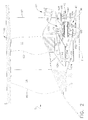
- FIGS. 1 and 2 Illustrated in FIGS. 1 and 2 is an exemplary turbofan gas turbine engine 10 circumscribed about an engine centerline 11 and having a counter-rotatable fan section 16 which receives inlet airflow of ambient air 5.
- the fan section 16 includes counter-rotatable first and second fan stages 60, 62 having fan blades 14.
- One of the first and second fan stages 60, 62 is rotatable in a clockwise direction about the engine centerline 11 and another of the fan stages is rotatable in a counter-clockwise direction about the engine centerline 11.
- the first and second fan stages 60, 62 may be described as being counter-rotatable with respect to each other and are at least in part radially supported by a fan frame 67.
- a booster compressor 24 downstream and aft of the fan section 16, in downstream serial flow relationship, is a booster compressor 24, a high pressure multi-stage axial-flow compressor (HPC) 26, a combustor 28, a high pressure turbine (HPT) 30, and a low pressure turbine (LPT) 32 from which the combustion gases are discharged from the engine 10.
- the combustor 28 mixes fuel with the air 5 pressurized by the HPC 26 for generating combustion gases which flow downstream through the high pressure turbine (HPT) 30.
- a high pressure shaft 34 joins the HPT 30 to the HPC 26.
- the high pressure compressor 26, combustor 28, and high pressure turbine 30 collectively are referred to as a core engine 12 which includes, for the purposes of this patent, the high pressure shaft 34.
- the counter-rotatable first and second fan stages 60, 62 are drivenly connected to the low pressure turbine (LPT) 32 by a low pressure shaft 36 through an epicyclic gear train 40 in an epicyclic gearbox 56 so as to be counter-rotatable with respect to each other.
- the gearbox 56 is disposed within a fan cavity 57 of the engine 10 and axially and radially supported by the fan frame 67.
- the epicyclic gear train 40 and gearbox 56 includes an annular planetary gear carrier 72 supported by the fan frame 67 and planetary gears 74 rotatably mounted on spindles 75 supported by forward and aft conical carrier frames 76, 77 of an annular carrier 72.
- the forward and aft conical carrier frames 76, 77 include radially outer forward and aft carrier flanges 79, 81 respectively mounted to and supported by the fan frame 67.
- the forward and aft conical carrier frames 76, 77 include radially inner forward and aft support flanges 83, 85 respectively fixedly supporting the spindles 75 therebetween.
- the forward and aft support flanges 83, 85 are connected by conical forward and aft support beams 88, 90 to the forward and aft carrier flanges 79, 81 respectively, thus, forming cage 91 to rotatably support the planetary gears 74.
- the forward and aft support beams 88, 90 are circumferentially disposed between the planetary gears 74.
- Each of the planetary gears 74 includes axially spaced apart forward and aft sets of output teeth 94, 96 extending radially outwardly from a hollow planetary gear hub 92.
- the forward set of output teeth 94 of the planetary gears 74 meshes with a second fan ring gear 100 connected to and operable to drive the second fan stage 62.
- the aft set of output teeth 96 of the planetary gears 74 meshes with a first fan external gear 102 connected to and operable to drive the first fan stage 60.
- An external gear is one with the teeth formed on the outer surface of a hub, a cylinder, or a cone.
- an internal or ring gear is one with the teeth formed on the inner surface of a hub, a cylinder, or a cone.
- An input gear 104 is fixedly attached to the planetary gear hub 92 aft of the aft set of output teeth 96.
- the input gear 104 of each of the planetary gears 74 meshes with a sun gear 108 directly connected to the low pressure shaft 36.
- the sun gear 108 meshes with the input gear 104 of each of the planetary gears 74 radially inwardly of the spindles 75.
- the forward set of output teeth 94 meshes with the second fan ring gear 100 radially outwardly of the spindles 75 and the aft set of output teeth 96 meshes with the first fan external gear 102 radially outwardly of the spindles 75 in order to counter rotate the first and second fan stages 60, 62.
- the forward and aft support beams 88, 90 are circumferentially disposed between the forward and aft set of output teeth 94, 96 and the input gear 104.
- Axially spaced apart forward and aft roller bearings 111, 112 are disposed between the planetary gears 74 and the spindles 75.
- the forward and aft roller bearings 111, 112 are axially aligned with or adjacent to the spaced apart forward set of output teeth 94 and the input gear 104 respectively.
- the forward roller bearing 111 is axially aligned with the forward set of output teeth 94 and the aft roller bearing 112 is axially adjacent to the input gear 104.
- the forward and aft roller bearings 111, 112 are disposed within forward and aft races 116, 118 mounted to the spindles 75 and radially disposed between the forward and aft races 116, 118 and forward and aft hub sections 120, 122 of the planetary gear hub 92 respectively.
- gear tooth forces of the axially spaced apart forward and aft sets of output teeth 94, 96 when they mesh with the second fan ring gear 100 and the first fan external gear 102 respectively generate moments that greatly reduce the bearing reaction loads and the loads on the planet carrier.
- the arrangement of the axially spaced apart forward and aft sets of output teeth 94, 96 and the input gear 104 provides a means to position the outer forward and aft carrier flanges 79, 81 at an optimized axial location to equalize the deflection of the spindles 75 and planetary gear hub 92 at the forward and aft roller bearings 111, 112, resulting in minimal gear tooth misalignment.
- the gear tooth forces of the axially displaced internal ring gear mesh result in an overturning moment on each planet gear assembly that reduces the radial loads at the forward and aft roller bearings 111, 112.
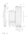
- the planetary gears 74 and their mating teeth or gears are helical as illustrated in FIG. 5 .
- the forward and aft set of output teeth 94, 96, and the input gear 104 of the planetary gears 74 are illustrated as having right hand helical teeth 130.
- the second fan ring gear 100, the first fan external gear 102, and the sun gear 108 are illustrated as having left hand helical teeth 132. They may of course be reversed.
- the right and left hand helical teeth 130, 132 provide a strong robust mesh and have a helix angle 134 that is selected to create a planetary gear moment to reduce the bearing radial loads caused by the gear tooth separating forces.
- the helix angles are selected to balance the axial force of the input mesh between the input gear 104 of the planetary gears 74 and the sun gear 108 with the sum of the axial forces of the two output meshes of the forward set of output teeth 94 of the planetary gears 74 with the second fan ring gear 100 and the aft set of output teeth 96 of the planetary gears 74 with the first fan external gear 102.
- the input sun gear 108 has a first axial force that is in the opposite direction to that of the low pressure turbine 32, and each of the second fan ring gear 100 and the first fan external gear 102 has a second axial force that is in the opposite direction to that of the fan thrust.
- the net thrust loads that are reacted by the low pressure turbine and fan bearings and their supporting structure are therefore greatly reduced.
- the first fan stage 60 is connected by a first cone 124 to the first fan external gear 102.
- the second fan stage 62 is connected by a second cone 126 to the second fan ring gear 100.
- a thrust bearing 140 includes a radially outer race 146 fixedly coupled to the fan frame 67 and is operable for transferring thrust loads developed or generated by counter-rotating from the counter-rotatable first and second fan stages 60, 62 of the fan section 16 to the fan frame 67.
- Fan thrust roller bearings 148 are disposed between inner race 142 and the outer race 146 of the thrust bearing 140.
- Axially spaced apart forward differential roller bearing 150 and aft thrust roller bearing 152 are radially disposed between the first cone 124 and the low pressure shaft 36.
- a thrust first ball bearing 154 is radially disposed between the second cone 126 and the first cone 124 thus providing thrust load transferring from the counter-rotatable first and second fan stages 60, 62 to be transferred to the fan frame 67.
- a differential third roller bearing 162 is radially disposed between the second cone 126 and an axially forwardly extending cone 115 of the fan frame 67. The third roller bearing 162 also provides radial support for the first and second fan stages 60, 62.
- the bearings facilitate maintaining the first and second fan stages 60, 62 in a relatively fixed axial and radial positions as well as transferring thrust loads and/or forces generated by the first and second fan stages 60, 62 to the fan frame 67.
- a fan frame thrust bearing 170 is disposed between the frame 67 and second fan ring gear 100 attached to the second cone 126 to provide thrust transfer from the second fan stage 62 to the fan frame 67.
- the forward differential roller bearing 150 and aft thrust roller bearing 152 and the first ball bearing 154 function as differential bearings to support and/or transfer thrust loads and/or forces from the first and second fan stages 60, 62 to the thrust bearing 140.
Abstract
Description
- The invention relates to epicyclic gearboxes with particular application to aircraft gas turbine engines with counter-rotatable fans.
- An aircraft gas turbine engine of the turbofan type generally includes a forward fan and booster compressor, a middle core engine, and an aft low pressure power turbine. The core engine includes a high pressure compressor, a combustor, and a high pressure turbine in a serial flow relationship. The high pressure compressor and high pressure turbine of the core engine are interconnected by a high pressure shaft. The high pressure compressor, turbine, and shaft essentially form the high pressure rotor or spool. The high pressure compressor is rotatably driven to compress air entering the core engine to a relatively high pressure. This high pressure air is then mixed with fuel in the combustor and ignited to form a high energy gas stream. The gas stream flows aft and passes through the high pressure turbine, rotatably driving it and the high pressure shaft which, in turn, rotatably drives the compressor. The gas stream leaving the high pressure turbine is expanded through a second or low pressure turbine. The low pressure turbine rotatably drives the fan and booster compressor via a low pressure shaft, all of which form the low pressure rotor or spool. The low pressure shaft extends through the high pressure rotor.
- Some fan jet engines have been designed with counter-rotating fans and some with counter-rotating fans and/or boosters or low pressure compressors.
U.S. Patent Nos. 4,790,133 ,4,860,537 ,5,307,622 and6,732,502 disclose counter-rotating low pressure turbines (LPT) that power counter-rotating fans and booster or low pressure compressors. Most of the thrust produced is generated by the fan. There are also various designs for counter-rotating fan engines that use gearboxes to effect counter-rotation of the fans and boosters. Counter-rotating fans, boosters, and turbines greatly enhance the engine's fuel efficiency. United States Patent Application Serial No.11/555,042 - Size, weight, and reliability of an epicyclic gearbox depends a great deal on planet bearing loads, life requirements, and gear tooth stresses. It is highly desirable to significantly reduce the planet bearing loads of a counter-rotating epicyclic gearbox in order to increase gearbox reliability. It is also highly desirable to reduced loads enabling the use of smaller bearings which reduces weight and improves life of the gearbox. Smaller bearings also decrease the heat generation of the gearbox which results in an efficiency improvement and reduced oil flow requirements.
- It is also highly desirable to reduce or eliminate gear misalignment that results from the twisting due to torque. Improved alignment reduces or eliminates the need to modify gear tooth shape to compensate for deflection, resulting in improved gear durability and reduced gear tooth stresses.
- An epicyclic gear train includes planetary gears rotatably mounted on spindles supported by an annular carrier. Each of the planetary gears includes axially spaced apart forward and aft sets of output teeth extending radially outwardly from a hollow planetary gear hub. Axially spaced apart forward and aft roller bearings are disposed between the planetary gears and the spindles.
- An exemplary embodiment of the epicyclic gear train further includes the forward and aft roller bearings being axially aligned with or adjacent to the spaced apart forward and aft sets of output teeth. An input gear is fixedly attached to the planetary gear hub aft of the aft set of output teeth of each of the each of the planetary gears. In a more particular embodiment, the forward roller bearing is axially aligned with the forward set of output teeth and the aft roller bearing is axially adjacent to the input gear.
- The exemplary embodiment of the epicyclic gear train further includes a ring gear circumscribing and engaging the forward set of output teeth and an external gear meshing with the aft set of output teeth. The input gear meshes with a sun gear. The forward set of output teeth meshes with the ring gear radially outwardly of the spindles and the aft set of output teeth meshes with the external gear radially outwardly of the spindles. The input gear of each of the planetary gears meshes with the sun gear radially inwardly of the spindles. The forward and aft set of output teeth, the input gear of the planetary gears, the ring gear, the external gear, and the sun gear may be helical.
- The epicyclic gear train may be used in an epicyclic gearbox further including the spindles supported by forward and aft conical carrier frames of the annular carrier. The forward and aft conical carrier frames include radially outer forward and aft carrier flanges respectively, radially inner forward and aft support flanges respectively fixedly supporting the spindles therebetween and connected by conical forward and aft support beams to the forward and aft carrier flanges.
- A turbofan gas turbine engine may incorporate the epicyclic gearbox to counter rotatably drive counter-rotatable first and second fan stages radially supported, at least in part, by a fan frame in a fan section of the engine. A low pressure turbine downstream of the fan section is drivingly connected to the first and second fan stages by a low pressure shaft through the epicyclic gear train in the epicyclic gearbox. In an exemplary embodiment of the engine, the second fan stage is connected to a ring gear circumscribing and meshing with the forward set of output teeth, the first fan stage is connected to the external gear meshing with the aft set of output teeth, the input gear is fixedly attached to the planetary gear hub aft of the aft set of output teeth of each of the planetary gears, and the input gear of each of the planetary gears meshes with the sun gear connected to the low pressure shaft. The forward and aft carrier flanges of the forward and aft conical carrier frames are mounted to and supported by the fan frame.
- The foregoing aspects and other features of the invention are explained in the following description, taken in connection with the accompanying drawings where:
-
FIG. 1 is a longitudinal sectional view diagrammatical illustration of an exemplary embodiment of an aircraft turbofan gas turbine engine with counter-rotatable forward and aft fans driven by low pressure turbine through an epicyclic gearbox in which each planetary gear includes forward and aft sets of teeth mounted on a common cylinder. -
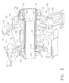
FIG. 2 is an enlarged more detailed longitudinal sectional view illustration of the epicyclic gearbox connected to the counter-rotatable fans illustrated inFIG. 1 . -
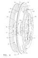
FIG. 3 is perspective view diagrammatical illustration of an epicyclic gear train in the gearbox illustrated inFIG. 2 . -
FIG. 4 is perspective view diagrammatical illustration of the gear train illustrated inFIG. 3 . -
FIG. 5 is side view diagrammatical illustration of a helical planetary gear in the gear train illustrated inFIG. 3 . - Illustrated in
FIGS. 1 and2 is an exemplary turbofangas turbine engine 10 circumscribed about anengine centerline 11 and having acounter-rotatable fan section 16 which receives inlet airflow of ambient air 5. Thefan section 16 includes counter-rotatable first andsecond fan stages fan blades 14. One of the first andsecond fan stages engine centerline 11 and another of the fan stages is rotatable in a counter-clockwise direction about theengine centerline 11. Thus, the first andsecond fan stages fan frame 67. - Referring to
FIG. 1 , downstream and aft of thefan section 16, in downstream serial flow relationship, is abooster compressor 24, a high pressure multi-stage axial-flow compressor (HPC) 26, acombustor 28, a high pressure turbine (HPT) 30, and a low pressure turbine (LPT) 32 from which the combustion gases are discharged from theengine 10. Thecombustor 28 mixes fuel with the air 5 pressurized by theHPC 26 for generating combustion gases which flow downstream through the high pressure turbine (HPT) 30. Ahigh pressure shaft 34 joins the HPT 30 to the HPC 26. Thehigh pressure compressor 26,combustor 28, andhigh pressure turbine 30 collectively are referred to as acore engine 12 which includes, for the purposes of this patent, thehigh pressure shaft 34. - Referring to
FIGS. 1 and2 , the counter-rotatable first andsecond fan stages low pressure shaft 36 through anepicyclic gear train 40 in anepicyclic gearbox 56 so as to be counter-rotatable with respect to each other. Thegearbox 56 is disposed within afan cavity 57 of theengine 10 and axially and radially supported by thefan frame 67. - The
epicyclic gear train 40 andgearbox 56, as further illustrated inFIGS. 3 and4 , includes an annularplanetary gear carrier 72 supported by thefan frame 67 andplanetary gears 74 rotatably mounted onspindles 75 supported by forward and aftconical carrier frames annular carrier 72. The forward and aftconical carrier frames aft carrier flanges fan frame 67. The forward and aftconical carrier frames aft support flanges spindles 75 therebetween. The forward andaft support flanges aft support beams aft carrier flanges cage 91 to rotatably support theplanetary gears 74. The forward and aft support beams 88, 90 are circumferentially disposed between theplanetary gears 74. - Each of the
planetary gears 74 includes axially spaced apart forward and aft sets ofoutput teeth planetary gear hub 92. The forward set ofoutput teeth 94 of theplanetary gears 74 meshes with a secondfan ring gear 100 connected to and operable to drive thesecond fan stage 62. The aft set ofoutput teeth 96 of theplanetary gears 74 meshes with a first fanexternal gear 102 connected to and operable to drive thefirst fan stage 60. An external gear is one with the teeth formed on the outer surface of a hub, a cylinder, or a cone. Conversely, an internal or ring gear is one with the teeth formed on the inner surface of a hub, a cylinder, or a cone. Aninput gear 104 is fixedly attached to theplanetary gear hub 92 aft of the aft set ofoutput teeth 96. Theinput gear 104 of each of theplanetary gears 74 meshes with asun gear 108 directly connected to thelow pressure shaft 36. Thesun gear 108 meshes with theinput gear 104 of each of theplanetary gears 74 radially inwardly of thespindles 75. The forward set ofoutput teeth 94 meshes with the secondfan ring gear 100 radially outwardly of thespindles 75 and the aft set ofoutput teeth 96 meshes with the first fanexternal gear 102 radially outwardly of thespindles 75 in order to counter rotate the first and second fan stages 60, 62. The forward and aft support beams 88, 90 are circumferentially disposed between the forward and aft set ofoutput teeth input gear 104. - Axially spaced apart forward and
aft roller bearings planetary gears 74 and thespindles 75. The forward andaft roller bearings output teeth 94 and theinput gear 104 respectively. In the exemplary embodiment of thegearbox 56 illustrated herein, theforward roller bearing 111 is axially aligned with the forward set ofoutput teeth 94 and theaft roller bearing 112 is axially adjacent to theinput gear 104. The forward andaft roller bearings aft races spindles 75 and radially disposed between the forward andaft races aft hub sections planetary gear hub 92 respectively. - Referring to
FIGS. 4 and5 , gear tooth forces of the axially spaced apart forward and aft sets ofoutput teeth fan ring gear 100 and the first fanexternal gear 102 respectively generate moments that greatly reduce the bearing reaction loads and the loads on the planet carrier. The arrangement of the axially spaced apart forward and aft sets ofoutput teeth input gear 104 provides a means to position the outer forward andaft carrier flanges spindles 75 andplanetary gear hub 92 at the forward andaft roller bearings aft roller bearings - In a preferred embodiment of the
gearbox 56, theplanetary gears 74 and their mating teeth or gears are helical as illustrated inFIG. 5 . The forward and aft set ofoutput teeth input gear 104 of theplanetary gears 74 are illustrated as having right handhelical teeth 130. The secondfan ring gear 100, the first fanexternal gear 102, and thesun gear 108 are illustrated as having left handhelical teeth 132. They may of course be reversed. The right and left handhelical teeth helix angle 134 that is selected to create a planetary gear moment to reduce the bearing radial loads caused by the gear tooth separating forces. The helix angles are selected to balance the axial force of the input mesh between theinput gear 104 of theplanetary gears 74 and thesun gear 108 with the sum of the axial forces of the two output meshes of the forward set ofoutput teeth 94 of theplanetary gears 74 with the secondfan ring gear 100 and the aft set ofoutput teeth 96 of theplanetary gears 74 with the first fanexternal gear 102. - The
input sun gear 108 has a first axial force that is in the opposite direction to that of thelow pressure turbine 32, and each of the secondfan ring gear 100 and the first fanexternal gear 102 has a second axial force that is in the opposite direction to that of the fan thrust. The net thrust loads that are reacted by the low pressure turbine and fan bearings and their supporting structure are therefore greatly reduced. - Referring to
FIG. 2 , thefirst fan stage 60 is connected by afirst cone 124 to the first fanexternal gear 102. Thesecond fan stage 62 is connected by asecond cone 126 to the secondfan ring gear 100. Athrust bearing 140 includes a radiallyouter race 146 fixedly coupled to thefan frame 67 and is operable for transferring thrust loads developed or generated by counter-rotating from the counter-rotatable first and second fan stages 60, 62 of thefan section 16 to thefan frame 67. Fan thrustroller bearings 148 are disposed betweeninner race 142 and theouter race 146 of thethrust bearing 140. - Axially spaced apart forward
differential roller bearing 150 and aftthrust roller bearing 152 are radially disposed between thefirst cone 124 and thelow pressure shaft 36. A thrustfirst ball bearing 154 is radially disposed between thesecond cone 126 and thefirst cone 124 thus providing thrust load transferring from the counter-rotatable first and second fan stages 60, 62 to be transferred to thefan frame 67. A differentialthird roller bearing 162 is radially disposed between thesecond cone 126 and an axially forwardly extendingcone 115 of thefan frame 67. Thethird roller bearing 162 also provides radial support for the first and second fan stages 60, 62. The bearings facilitate maintaining the first and second fan stages 60, 62 in a relatively fixed axial and radial positions as well as transferring thrust loads and/or forces generated by the first and second fan stages 60, 62 to thefan frame 67. A fan frame thrust bearing 170 is disposed between theframe 67 and secondfan ring gear 100 attached to thesecond cone 126 to provide thrust transfer from thesecond fan stage 62 to thefan frame 67. The forwarddifferential roller bearing 150 and aftthrust roller bearing 152 and thefirst ball bearing 154 function as differential bearings to support and/or transfer thrust loads and/or forces from the first and second fan stages 60, 62 to thethrust bearing 140. - The present invention has been described in an illustrative manner. It is to be understood that the terminology which has been used is intended to be in the nature of words of description rather than of limitation. While there have been described herein, what are considered to be preferred and exemplary embodiments of the present invention, other modifications of the invention shall be apparent to those skilled in the art from the teachings herein and, it is, therefore, desired to be secured in the appended claims all such modifications as fall within the true spirit and scope of the invention.
- For completeness, various aspects of the invention are now set out in the following numbered clauses:
- 1. An epicyclic gear train comprising:
- planetary gears rotatably mounted on spindles supported by an annular carrier,
- each of the planetary gears including a hollow planetary gear hub and axially spaced apart forward and aft sets of output teeth extending radially outwardly from the planetary gear hub, and
- axially spaced apart forward and aft roller bearings disposed between the planetary gears and the spindles.
- 2. An epicyclic gear train as claimed in clause 1, further comprising an input gear fixedly attached to the planetary gear hub aft of the aft set of output teeth of each of the each of the planetary gears.
- 3. An epicyclic gear train as claimed in
clause 2, further comprising the forward and aft roller bearing being axially aligned with or adjacent to the spaced apart forward set of output teeth and the input gear respectively. - 4. An epicyclic gear train as claimed in clause 3, further comprising the forward roller bearing being axially aligned with the forward set of output teeth and the aft roller bearing being axially adjacent to the input gear.
- 5. An epicyclic gear train as claimed in clause 1, further comprising a ring gear circumscribing and meshing with the forward set of output teeth and an external gear meshing with the aft set of output teeth.
- 6. An epicyclic gear train as claimed in clause 5, further comprising an input gear fixedly attached to the planetary gear hub aft of the aft set of output teeth of each of the each of the planetary gears.
- 7. An epicyclic gear train as claimed in clause 6, further comprising the input gear of each of the planetary gears meshing with a sun gear.
- 8. An epicyclic gear train as claimed in clause 6, further comprising the forward set of output teeth meshing with the ring gear radially outwardly of the spindles and the aft set of output teeth meshing with the external gear radially inwardly of the spindles.
- 9. An epicyclic gear train as claimed in clause 8, further comprising the input gear of each of the planetary gears meshing with the sun gear radially inwardly of the spindles.
- 10. An epicyclic gear train as claimed in clause 9, further comprising the forward and aft roller bearing being axially aligned with or adjacent to the spaced apart forward set of output teeth and the input gear respectively.
- 11. An epicyclic gear train as claimed in
clause 10, further comprising the forward and aft set of output teeth, the input gear of the planetary gears, the ring gear, the external gear, and the sun gear being helical. - 12. An epicyclic gear train as claimed in
clause 10, further comprising the forward roller bearing being axially aligned with the forward set of output teeth and the aft roller bearing being axially adjacent to the input gear. - 13. An epicyclic gear train as claimed in
clause 12, further comprising the forward and aft set of output teeth, the input gear of the planetary gears, the ring gear, the external gear, and the sun gear being helical. - 14. An epicyclic gearbox comprising:
- an epicyclic gear train including planetary gears rotatably mounted on spindles supported by forward and aft conical carrier frames of an annular carrier,
- the forward and aft conical carrier frames including radially outer forward and aft carrier flanges respectively,
- the forward and aft conical carrier frames including radially inner forward and aft support flanges respectively fixedly supporting the spindles therebetween,
- the forward and aft support flanges connected by conical forward and aft support beams to the forward and aft carrier flanges,
- each of the planetary gears including a hollow planetary gear hub and axially spaced apart forward and aft sets of output teeth extending radially outwardly from the planetary gear hub,
- an input gear fixedly attached to the planetary gear hub aft of the aft set of output teeth of each of the each of the planetary gears,
- the input gear of each of the planetary gears meshing with a sun gear, and
- axially spaced apart forward and aft roller bearings disposed between the planetary gears and the spindles.
- 15. An epicyclic gearbox as claimed in
clause 14, further comprising the forward and aft roller bearing being axially aligned with or adjacent to the spaced apart forward set of output teeth and the input gear respectively. - 16. An epicyclic gearbox as claimed in clause 15, further comprising the forward roller bearing being axially aligned with the forward set of output teeth and the aft roller bearing being axially adjacent to the input gear.
- 17. An epicyclic gearbox as claimed in clause 15, further comprising:
- the forward set of output teeth meshing with the ring gear radially outwardly of the spindles,
- the aft set of output teeth meshing with the external gear radially inwardly of the spindles, and
- the input gear of each of the planetary gears meshing with the sun gear radially inwardly of the spindles.
- 18. An epicyclic gearbox as claimed in clause 17, further comprising the forward and aft set of output teeth, the input gear of the planetary gears, the ring gear, the external gear, and the sun gear being helical.
- 19. A turbofan gas turbine engine comprising:
- a fan section including counter-rotatable first and second fan stages radially supported, at least in part, by a fan frame,
- a low pressure turbine downstream of the fan section and drivingly connected to the first and second fan stages by a low pressure shaft through an epicyclic gear train in an epicyclic gearbox,
- the epicyclic gear train including planetary gears rotatably mounted on spindles supported by an annular carrier,
- each of the planetary gears including a hollow planetary gear hub and axially spaced apart forward and aft sets of output teeth extending radially outwardly from the planetary gear hub, and
- axially spaced apart forward and aft roller bearings disposed between the planetary gears and the spindles.
- 20. A turbofan gas turbine engine as claimed in clause 19, further comprising an input gear fixedly attached to the planetary gear hub aft of the aft set of output teeth of each of the each of the planetary gears.
- 21. A turbofan gas turbine engine as claimed in clause 20, further comprising the forward and aft roller bearing being axially aligned with or adjacent to the spaced apart forward set of output teeth and the input gear respectively.
- 22. A turbofan gas turbine engine as claimed in clause 21, further comprising the forward roller bearing being axially aligned with the forward set of output teeth and the aft roller bearing being axially adjacent to the input gear.
- 23. A turbofan gas turbine engine as claimed in clause 20, further comprising:
- the second fan stage connected to a ring gear circumscribing and meshing with the forward set of output teeth,
- the first fan stage connected to an external gear meshing with the aft set of output teeth,
- an input gear fixedly attached to the planetary gear hub aft of the aft set of output teeth of each of the each of the planetary gears, and
- the input gear of each of the planetary gears meshing with a sun gear connected to the low pressure shaft.
- 24. A turbofan gas turbine engine as claimed in clause 23, further comprising:
- the forward set of output teeth meshing with the ring gear radially outwardly of the spindles,
- the aft set of output teeth meshing with the external gear radially inwardly of the spindles, and
- the input gear of each of the planetary gears meshing with the sun gear radially inwardly of the spindles.
- 25. A turbofan gas turbine engine as claimed in
clause 24, further comprising the forward and aft roller bearing being axially aligned with or adjacent to the spaced apart forward set of output teeth and the input gear respectively. - 26. A turbofan gas turbine engine as claimed in clause 25, further comprising the forward and aft set of output teeth, the input gear of the planetary gears, the ring gear, the external gear, and the sun gear being helical.
- 27. A turbofan gas turbine engine as claimed in clause 25, further comprising the forward roller bearing being axially aligned with the forward set of output teeth and the aft roller bearing being axially adjacent to the input gear.
- 28. A turbofan gas turbine engine as claimed in clause 27, further comprising the forward and aft set of output teeth, the input gear of the planetary gears, the ring gear, the external gear, and the sun gear being helical.
- 29. A turbofan gas turbine engine as claimed in clause 25, further comprising the spindles supported by forward and aft conical carrier frames of the annular carrier,
the forward and aft conical carrier frames including radially outer forward and aft carrier flanges respectively and mounted to and supported by the fan frame,
the forward and aft conical carrier frames including radially inner forward and aft support flanges respectively fixedly supporting the spindles therebetween, and
the forward and aft support flanges connected by conical forward and aft support beams to the forward and aft carrier flanges.
Claims (9)
- An epicyclic gear train (40) comprising:planetary gears (74) rotatably mounted on spindles (75) supported by an annular carrier (72),each of the planetary gears (74) including a hollow planetary gear hub (92) andaxially spaced apart forward and aft sets of output teeth (94, 96) extending radially outwardly from the planetary gear hub (92), andaxially spaced apart forward and aft roller bearings (111, 112) disposed between the planetary gears (74) and the spindles (75).
- An epicyclic gear train (40) as claimed in claim 1, further comprising an input gear (104) fixedly attached to the planetary gear hub (92) aft of the aft set of output teeth (96) of each of the each of the planetary gears (74).
- An epicyclic gear train (40) as claimed in claim 2, further comprising the forward and aft roller bearing (111, 112) being axially aligned with or adjacent to the spaced apart forward set of output teeth (94) and the input gear (104) respectively.
- An epicyclic gear train (40) as claimed in claim 3, further comprising the forward roller bearing (111) being axially aligned with the forward set of output teeth (94) and the aft roller bearing (112) being axially adjacent to the input gear (104).
- An epicyclic gear train (40) as claimed in any of the preceding claims, further comprising:a ring gear (100) circumscribing and meshing with the forward set of output teeth (94) and an external gear (102) meshing with the aft set of output teeth (96),an input gear (104) fixedly attached to the planetary gear hub (92) aft of the aft set of output teeth (96) of each of the each of the planetary gears (74), andthe input gear (104) of each of the planetary gears (74) meshing with a sun gear (108).
- An epicyclic gear train (40) as claimed in claim 5, further comprising:the forward set of output teeth (94) meshing with the ring gear (100) radially outwardly of the spindles (75),the aft set of output teeth (96) meshing with the external gear (102) radially inwardly of the spindles (75), andthe input gear (104) of each of the planetary gears (74) meshing with the sun gear (108) radially inwardly of the spindles (75).
- An epicyclic gear train (40) as claimed in claim 6, further comprising the forward and aft roller bearing (111, 112) being axially aligned with or adjacent to the spaced apart forward set of output teeth (94) and the input gear (104) respectively.
- An epicyclic gear train (40) as claimed in claim 6, further comprising the forward and aft set of output teeth (94, 96), the input gear (104) of the planetary gears (74), the ring gear (100), the external gear (102), and the sun gear (108) being helical.
- An epicyclic gearbox (56) comprising:an epicyclic gear train (40) including planetary gears (74) rotatably mounted on spindles (75) supported by forward and aft conical carrier frames (76, 77) of an annular carrier (72),the forward and aft conical carrier frames (76, 77) including radially outer forward and aft carrier flanges (79, 81) respectively,the forward and aft conical carrier frames (76, 77) including radially inner forward and aft support flanges (83, 85) respectively fixedly supporting the spindles (75) therebetween,the forward and aft support flanges (83, 85) connected by conical forward and aft support beams (88, 90) to the forward and aft carrier flanges (79, 81),each of the planetary gears (74) including a hollow planetary gear hub (92) andaxially spaced apart forward and aft sets of output teeth (94, 96) extending radially outwardly from the planetary gear hub (92),an input gear (104) fixedly attached to the planetary gear hub (92) aft of the aft set of output teeth (96) of each of the each of the planetary gears (74),the input gear (104) of each of the planetary gears (74) meshing with a sun gear (108),andaxially spaced apart forward and aft roller bearings (111, 112) disposed between the planetary gears (74) and the spindles (75).
Applications Claiming Priority (1)
| Application Number | Priority Date | Filing Date | Title |
|---|---|---|---|
| US12/710,720 US8517672B2 (en) | 2010-02-23 | 2010-02-23 | Epicyclic gearbox |
Publications (2)
| Publication Number | Publication Date |
|---|---|
| EP2360391A1 true EP2360391A1 (en) | 2011-08-24 |
| EP2360391B1 EP2360391B1 (en) | 2014-04-09 |
Family
ID=43929016
Family Applications (1)
| Application Number | Title | Priority Date | Filing Date |
|---|---|---|---|
| EP11155563.7A Active EP2360391B1 (en) | 2010-02-23 | 2011-02-23 | Epicyclic Gearbox |
Country Status (5)
| Country | Link |
|---|---|
| US (1) | US8517672B2 (en) |
| EP (1) | EP2360391B1 (en) |
| JP (1) | JP5814559B2 (en) |
| CA (1) | CA2731914C (en) |
| ES (1) | ES2464050T3 (en) |
Cited By (23)
| Publication number | Priority date | Publication date | Assignee | Title |
|---|---|---|---|---|
| DE102011084360A1 (en) * | 2011-10-12 | 2013-04-18 | Rolls-Royce Deutschland Ltd & Co Kg | Flow working machine for use in aircraft engine, has main rotor disk or drum driven by main shaft, and auxiliary rotor disk or drum driven by auxiliary shaft, where shafts comprise different rotational speed and/or rotational direction |
| FR2991421A1 (en) * | 2012-05-30 | 2013-12-06 | Snecma | EPICYCLOIDAL TRAIN REDUCER WITH BEARING-BASED SATELLITE AXES |
| EP2915962A1 (en) * | 2014-03-07 | 2015-09-09 | United Technologies Corporation | Geared turbofan with integral front support and carrier |
| CN104995436A (en) * | 2013-03-29 | 2015-10-21 | 住友重机械工业株式会社 | Reducer |
| FR3023586A1 (en) * | 2014-07-08 | 2016-01-15 | Snecma | AIRCRAFT TURBOMACHINE COMPRISING A TWO-ROTOR BLOWER |
| EP3000988A1 (en) * | 2014-09-24 | 2016-03-30 | United Technologies Corporation | Fan drive gear system |
| EP3101258A1 (en) * | 2015-06-05 | 2016-12-07 | United Technologies Corporation | Geared architecture for a gas turbine engine |
| EP3109452A1 (en) * | 2015-06-23 | 2016-12-28 | United Technologies Corporation | Journal bearing for rotating gear carrier |
| EP3144487A1 (en) * | 2015-09-18 | 2017-03-22 | Rolls-Royce plc | A coupling for a geared turbo fan |
| EP3144486A1 (en) * | 2015-09-18 | 2017-03-22 | Rolls-Royce plc | A shafting arrangement for a gas turbine engine |
| WO2017158294A1 (en) * | 2016-03-15 | 2017-09-21 | Safran Aircraft Engines | Turbofan comprising a low-supercritical-pressure shaft |
| EP3296552A1 (en) * | 2016-09-20 | 2018-03-21 | Rolls-Royce Deutschland Ltd & Co KG | Gas turbine engine with a geared turbofan arrangement |
| EP3354940A1 (en) * | 2017-01-30 | 2018-08-01 | Rolls-Royce Deutschland Ltd & Co KG | Planetary gear system and gas turbine engine with a planetary gear system |
| EP3354939A1 (en) * | 2017-01-30 | 2018-08-01 | Rolls-Royce Deutschland Ltd & Co KG | Planetary gear system and gas turbine engine with a planetary gear system |
| US10428741B2 (en) | 2016-09-20 | 2019-10-01 | Rolls-Royce Deutschland Ltd & Co Kg | Gas turbine engine with a geared turbofan arrangement |
| EP3626935A1 (en) * | 2014-09-24 | 2020-03-25 | United Technologies Corporation | Fan drive gear system |
| US10626925B2 (en) | 2016-09-20 | 2020-04-21 | Rolls-Royce Deutschland Ltd & Co Kg | Gas turbine engine with a geared turbofan arrangement |
| US11156166B2 (en) | 2014-09-24 | 2021-10-26 | Raytheon Technologies Corporation | Fan drive gear system |
| US11365688B2 (en) | 2020-08-04 | 2022-06-21 | G.E. Avio S.r.l. | Gearbox efficiency rating for turbomachine engines |
| US11401829B2 (en) | 2020-08-04 | 2022-08-02 | Ge Avio S.R.L. | Gearbox efficiency rating for turbomachine engines |
| US11466624B1 (en) | 2022-01-31 | 2022-10-11 | Ge Avio S.R.L. | Overall engine efficiency rating for turbomachine engines |
| US11473507B2 (en) | 2020-08-04 | 2022-10-18 | Ge Avio S.R.L. | Gearbox efficiency rating for turbomachine engines |
| US11486312B2 (en) | 2020-08-04 | 2022-11-01 | Ge Avio S.R.L. | Gearbox efficiency rating for turbomachine engines |
Families Citing this family (66)
| Publication number | Priority date | Publication date | Assignee | Title |
|---|---|---|---|---|
| JP5936472B2 (en) * | 2011-11-01 | 2016-06-22 | 日産自動車株式会社 | Planetary gear carrier structure |
| ES2748828T3 (en) * | 2011-12-16 | 2020-03-18 | Martinez Casan Jose Ramon | Jet engine with sliding vane compressor |
| US8720306B2 (en) * | 2012-01-31 | 2014-05-13 | United Technologies Corporation | Turbine engine gearbox |
| US9169781B2 (en) | 2012-01-31 | 2015-10-27 | United Technologies Corporation | Turbine engine gearbox |
| US9080461B2 (en) | 2012-02-02 | 2015-07-14 | Pratt & Whitney Canada Corp. | Fan and boost joint |
| US9011076B2 (en) | 2012-02-29 | 2015-04-21 | United Technologies Corporation | Counter-rotating low pressure turbine with gear system mounted to turbine exhaust case |
| US9022725B2 (en) | 2012-02-29 | 2015-05-05 | United Technologies Corporation | Counter-rotating low pressure turbine with gear system mounted to turbine exhaust case |
| US9194290B2 (en) | 2012-02-29 | 2015-11-24 | United Technologies Corporation | Counter-rotating low pressure turbine without turbine exhaust case |
| US20130259651A1 (en) * | 2012-04-02 | 2013-10-03 | Daniel Bernard Kupratis | Differential geared architecture for gas turbine engine |
| US20130255274A1 (en) * | 2012-04-02 | 2013-10-03 | Daniel Bernard Kupratis | Geared architecture with speed change device for gas turbine engine |
| US9267389B2 (en) | 2012-06-05 | 2016-02-23 | United Technologies Corporation | Geared architecture carrier torque frame assembly |
| US20140314541A1 (en) * | 2012-09-26 | 2014-10-23 | United Technologies Corporation | Turbomachine thrust balancing system |
| US8807916B2 (en) | 2012-09-27 | 2014-08-19 | United Technologies Corporation | Method for setting a gear ratio of a fan drive gear system of a gas turbine engine |
| US8753065B2 (en) | 2012-09-27 | 2014-06-17 | United Technologies Corporation | Method for setting a gear ratio of a fan drive gear system of a gas turbine engine |
| US20140130479A1 (en) * | 2012-11-14 | 2014-05-15 | United Technologies Corporation | Gas Turbine Engine With Mount for Low Pressure Turbine Section |
| US8678743B1 (en) | 2013-02-04 | 2014-03-25 | United Technologies Corporation | Method for setting a gear ratio of a fan drive gear system of a gas turbine engine |
| US9752500B2 (en) * | 2013-03-14 | 2017-09-05 | Pratt & Whitney Canada Corp. | Gas turbine engine with transmission and method of adjusting rotational speed |
| WO2014151785A1 (en) * | 2013-03-15 | 2014-09-25 | United Technologies Corporation | Turbofan engine bearing and gearbox arrangement |
| WO2014151176A1 (en) * | 2013-03-15 | 2014-09-25 | United Technologies Corporation | Turbofan engine main bearing arrangement |
| US10190496B2 (en) * | 2013-03-15 | 2019-01-29 | United Technologies Corporation | Turbofan engine bearing and gearbox arrangement |
| WO2015012923A2 (en) | 2013-05-09 | 2015-01-29 | United Technologies Corporation | Turbofan engine front section |
| EP3008323B1 (en) | 2013-05-09 | 2021-11-10 | Raytheon Technologies Corporation | Turbofan engine front section |
| US10094278B2 (en) * | 2013-06-03 | 2018-10-09 | United Technologies Corporation | Turbofan engine bearing and gearbox arrangement |
| EP3108113A4 (en) * | 2014-02-19 | 2017-03-15 | United Technologies Corporation | Gas turbine engine airfoil |
| EP3108115B8 (en) * | 2014-02-19 | 2023-11-08 | RTX Corporation | Turbofan engine with geared architecture and lpc blades |
| WO2015126798A1 (en) * | 2014-02-19 | 2015-08-27 | United Technologies Corporation | Gas turbine engine airfoil |
| EP3108107B1 (en) | 2014-02-19 | 2023-10-11 | Raytheon Technologies Corporation | Turbofan engine with geared architecture and lpc airfoils |
| WO2015175052A2 (en) * | 2014-02-19 | 2015-11-19 | United Technologies Corporation | Gas turbine engine airfoil |
| EP3108120B1 (en) | 2014-02-19 | 2021-03-31 | Raytheon Technologies Corporation | Gas turbine engine having a geared architecture and a specific fixed airfoil structure |
| CN104021720B (en) * | 2014-06-10 | 2016-05-25 | 上海理工大学 | Cyclic train experiment teaching aid |
| US11448123B2 (en) | 2014-06-13 | 2022-09-20 | Raytheon Technologies Corporation | Geared turbofan architecture |
| US9878798B2 (en) | 2014-12-31 | 2018-01-30 | Rolls-Royce North American Technologies Inc. | Aircraft with counter-rotating turbofan engines |
| US11067005B2 (en) | 2015-02-03 | 2021-07-20 | Raytheon Technologies Corporation | Fan drive gear system |
| US9879694B2 (en) | 2015-02-03 | 2018-01-30 | United Technologies Corporation | Turbo-compressor with geared turbofan |
| US9909453B2 (en) | 2015-05-19 | 2018-03-06 | General Electric Company | Lubrication system for a turbine engine |
| US20170089218A1 (en) * | 2015-09-25 | 2017-03-30 | General Electric Company | Double row cylindrical roller bearing with high length to diameter ratio rollers |
| US10415429B2 (en) | 2015-09-25 | 2019-09-17 | General Electric Company | Planet gearbox with cylindrical roller bearing with high density roller packing |
| US10234018B2 (en) | 2015-10-19 | 2019-03-19 | General Electric Company | Planet gearbox with cylindrical roller bearing with under race lube scheme |
| FR3043714B1 (en) * | 2015-11-16 | 2017-12-22 | Snecma | FRONT AIRCRAFT TURBOMACHINE PART COMPRISING A SINGLE BLOWER CONDUCTED BY A REDUCER, AS WELL AS STRUCTURAL OUTPUT LEAD DIRECTORS FITTED PARTLY BEFORE A SEPARATION SPOUT |
| ITUB20156062A1 (en) | 2015-12-01 | 2017-06-01 | Gen Electric | HOUSING FOR USE IN A MOTOR-DRIVEN ENGINE AND WASHING PROCESS OF FLUID FROM IT. |
| US10066734B2 (en) | 2015-12-07 | 2018-09-04 | United Technologies Corporation | Gear driven gas turbine engine assembly |
| US10669947B2 (en) | 2016-07-11 | 2020-06-02 | Raytheon Technologies Corporation | Geared gas turbine engine |
| US10100875B2 (en) | 2016-07-26 | 2018-10-16 | General Electric Company | Roller bearing and systems including such |
| US10030708B2 (en) | 2016-07-29 | 2018-07-24 | General Electric Company | Roller bearing cage for use in a gearbox |
| US10138940B2 (en) | 2016-08-09 | 2018-11-27 | General Electric Company | Roller bearing cage for use in a gearbox |
| EP3296540B1 (en) | 2016-09-20 | 2019-01-23 | Rolls-Royce Deutschland Ltd & Co KG | Gas turbine engine with a geared turbofan arrangement |
| US10400678B2 (en) | 2017-01-03 | 2019-09-03 | General Electric Company | Apparatus and system for light-weight, flexible double-helical gear |
| US10508731B2 (en) | 2017-01-05 | 2019-12-17 | General Electric Company | Apparatus and method for managing pinch loads on a gear |
| US10247298B2 (en) | 2017-01-10 | 2019-04-02 | General Electric Company | Resilient bearing pin and gear assemblies including resilient bearing pins |
| US10228024B2 (en) | 2017-01-10 | 2019-03-12 | General Electric Company | Reduced-weight bearing pins and methods of manufacturing such bearing pins |
| US10247297B2 (en) | 2017-01-18 | 2019-04-02 | General Electric Company | Apparatus for a gearbox with multiple scavenge ports |
| US10408304B2 (en) | 2017-02-07 | 2019-09-10 | General Electric Company | Gears having reduced roller element stresses and methods of manufacturing such gears |
| GB201704173D0 (en) * | 2017-03-16 | 2017-05-03 | Rolls Royce Plc | Gas turbine engine |
| US10451113B2 (en) | 2017-05-18 | 2019-10-22 | General Electric Company | Bearing cages for roller bearing assemblies |
| US10260563B2 (en) | 2017-05-18 | 2019-04-16 | General Electric Company | Bearing cages for roller bearing assemblies |
| US10385961B2 (en) | 2017-10-25 | 2019-08-20 | General Electric Company | Planetary gear system |
| IT201800005822A1 (en) | 2018-05-29 | 2019-11-29 | ATTACHMENT OF A GEAR GROUP FOR A GAS TURBINE ENGINE | |
| EP3587773B1 (en) * | 2018-06-27 | 2022-06-08 | Rolls-Royce plc | Gas turbine |
| FR3087226B1 (en) * | 2018-10-10 | 2020-10-23 | Safran Aircraft Engines | AIRCRAFT TURBOMACHINE WITH MECHANICAL REDUCER AND CONTRAROTATING TURBINE |
| US11092020B2 (en) | 2018-10-18 | 2021-08-17 | Raytheon Technologies Corporation | Rotor assembly for gas turbine engines |
| US10844746B2 (en) * | 2019-03-29 | 2020-11-24 | Pratt & Whitney Canada Corp. | Bearing housing |
| US11268573B2 (en) * | 2020-03-25 | 2022-03-08 | Pratt & Whitney Canada Corp. | Bearing housing oil intake to supply dual bearing structure |
| CN114810348A (en) * | 2021-01-19 | 2022-07-29 | 中国航发商用航空发动机有限责任公司 | Transmission mechanism, turbofan engine and assembly method |
| IT202100018032A1 (en) | 2021-07-08 | 2023-01-08 | Ge Avio Srl | GAS TURBINE |
| US11867075B2 (en) | 2021-10-15 | 2024-01-09 | Rtx Corporation | Radial outward bearing support for a rotating structure of a turbine engine |
| DE102022109455A1 (en) * | 2022-04-19 | 2023-10-19 | MTU Aero Engines AG | GUIDE AND BLADE RING FOR A MANUAL ENGINE |
Citations (6)
| Publication number | Priority date | Publication date | Assignee | Title |
|---|---|---|---|---|
| US4790133A (en) | 1986-08-29 | 1988-12-13 | General Electric Company | High bypass ratio counterrotating turbofan engine |
| US4860537A (en) | 1986-08-29 | 1989-08-29 | Brandt, Inc. | High bypass ratio counterrotating gearless front fan engine |
| US5307622A (en) | 1993-08-02 | 1994-05-03 | General Electric Company | Counterrotating turbine support assembly |
| US5409430A (en) * | 1992-12-04 | 1995-04-25 | Tsubakimoto Chain Co. | Planetary gear system |
| US6732502B2 (en) | 2002-03-01 | 2004-05-11 | General Electric Company | Counter rotating aircraft gas turbine engine with high overall pressure ratio compressor |
| US20080098716A1 (en) * | 2006-10-31 | 2008-05-01 | Robert Joseph Orlando | Gas turbine engine assembly and methods of assembling same |
Family Cites Families (24)
| Publication number | Priority date | Publication date | Assignee | Title |
|---|---|---|---|---|
| US2472878A (en) * | 1942-04-29 | 1949-06-14 | Vickers Electrical Co Ltd | Fluid turbine power plant with speed reduction transmission gearing |
| US4251987A (en) * | 1979-08-22 | 1981-02-24 | General Electric Company | Differential geared engine |
| US4459876A (en) * | 1979-09-04 | 1984-07-17 | Caterpillar Tractor Co. | Floating planet gear system |
| GB8630754D0 (en) * | 1986-12-23 | 1987-02-04 | Rolls Royce Plc | Turbofan gas turbine engine |
| US4916894A (en) * | 1989-01-03 | 1990-04-17 | General Electric Company | High bypass turbofan engine having a partially geared fan drive turbine |
| US5010729A (en) * | 1989-01-03 | 1991-04-30 | General Electric Company | Geared counterrotating turbine/fan propulsion system |
| JPH0587352U (en) * | 1992-04-27 | 1993-11-26 | 石川島播磨重工業株式会社 | Reversing gear device with double reversing shaft |
| US6158210A (en) * | 1998-12-03 | 2000-12-12 | General Electric Company | Gear driven booster |
| FR2817912B1 (en) * | 2000-12-07 | 2003-01-17 | Hispano Suiza Sa | REDUCER TAKING OVER THE AXIAL EFFORTS GENERATED BY THE BLOWER OF A TURBO-JET |
| US6663530B2 (en) * | 2001-12-14 | 2003-12-16 | Pratt & Whitney Canada Corp. | Zero twist carrier |
| JP2006170413A (en) * | 2004-12-20 | 2006-06-29 | Seisa Gear Ltd | Bearing device for helical planetary reducer |
| US7493753B2 (en) * | 2005-10-19 | 2009-02-24 | General Electric Company | Gas turbine engine assembly and methods of assembling same |
| US7490460B2 (en) * | 2005-10-19 | 2009-02-17 | General Electric Company | Gas turbine engine assembly and methods of assembling same |
| US7752836B2 (en) * | 2005-10-19 | 2010-07-13 | General Electric Company | Gas turbine assembly and methods of assembling same |
| US7513103B2 (en) * | 2005-10-19 | 2009-04-07 | General Electric Company | Gas turbine engine assembly and methods of assembling same |
| US7685808B2 (en) * | 2005-10-19 | 2010-03-30 | General Electric Company | Gas turbine engine assembly and methods of assembling same |
| US7526913B2 (en) * | 2005-10-19 | 2009-05-05 | General Electric Company | Gas turbine engine assembly and methods of assembling same |
| US7926259B2 (en) * | 2006-10-31 | 2011-04-19 | General Electric Company | Turbofan engine assembly and method of assembling same |
| US7921634B2 (en) * | 2006-10-31 | 2011-04-12 | General Electric Company | Turbofan engine assembly and method of assembling same |
| US7966806B2 (en) * | 2006-10-31 | 2011-06-28 | General Electric Company | Turbofan engine assembly and method of assembling same |
| US7905083B2 (en) * | 2006-10-31 | 2011-03-15 | General Electric Company | Turbofan engine assembly and method of assembling same |
| US7882693B2 (en) * | 2006-11-29 | 2011-02-08 | General Electric Company | Turbofan engine assembly and method of assembling same |
| US7716914B2 (en) * | 2006-12-21 | 2010-05-18 | General Electric Company | Turbofan engine assembly and method of assembling same |
| JP2008303992A (en) * | 2007-06-08 | 2008-12-18 | Nsk Ltd | Radial needle roller bearing |
-
2010
- 2010-02-23 US US12/710,720 patent/US8517672B2/en active Active
-
2011
- 2011-02-16 JP JP2011030414A patent/JP5814559B2/en active Active
- 2011-02-17 CA CA2731914A patent/CA2731914C/en active Active
- 2011-02-23 EP EP11155563.7A patent/EP2360391B1/en active Active
- 2011-02-23 ES ES11155563.7T patent/ES2464050T3/en active Active
Patent Citations (6)
| Publication number | Priority date | Publication date | Assignee | Title |
|---|---|---|---|---|
| US4790133A (en) | 1986-08-29 | 1988-12-13 | General Electric Company | High bypass ratio counterrotating turbofan engine |
| US4860537A (en) | 1986-08-29 | 1989-08-29 | Brandt, Inc. | High bypass ratio counterrotating gearless front fan engine |
| US5409430A (en) * | 1992-12-04 | 1995-04-25 | Tsubakimoto Chain Co. | Planetary gear system |
| US5307622A (en) | 1993-08-02 | 1994-05-03 | General Electric Company | Counterrotating turbine support assembly |
| US6732502B2 (en) | 2002-03-01 | 2004-05-11 | General Electric Company | Counter rotating aircraft gas turbine engine with high overall pressure ratio compressor |
| US20080098716A1 (en) * | 2006-10-31 | 2008-05-01 | Robert Joseph Orlando | Gas turbine engine assembly and methods of assembling same |
Cited By (44)
| Publication number | Priority date | Publication date | Assignee | Title |
|---|---|---|---|---|
| DE102011084360A1 (en) * | 2011-10-12 | 2013-04-18 | Rolls-Royce Deutschland Ltd & Co Kg | Flow working machine for use in aircraft engine, has main rotor disk or drum driven by main shaft, and auxiliary rotor disk or drum driven by auxiliary shaft, where shafts comprise different rotational speed and/or rotational direction |
| DE102011084360B4 (en) * | 2011-10-12 | 2015-07-02 | Rolls-Royce Deutschland Ltd & Co Kg | Turbomachine |
| FR2991421A1 (en) * | 2012-05-30 | 2013-12-06 | Snecma | EPICYCLOIDAL TRAIN REDUCER WITH BEARING-BASED SATELLITE AXES |
| GB2504579A (en) * | 2012-05-30 | 2014-02-05 | Snecma | A reduction gear with epicyclic gear train having roller-bearing mounted planet spindles |
| US8986146B2 (en) | 2012-05-30 | 2015-03-24 | Snecma | Reduction gear with epicyclic gear train having roller-bearing-mounted planet spindles |
| GB2504579B (en) * | 2012-05-30 | 2018-06-27 | Snecma | Reduction gear with epicyclic gear train having roller-bearing-mounted planet spindles |
| CN104995436A (en) * | 2013-03-29 | 2015-10-21 | 住友重机械工业株式会社 | Reducer |
| US10280843B2 (en) | 2014-03-07 | 2019-05-07 | United Technologies Corporation | Geared turbofan with integral front support and carrier |
| EP3428409A1 (en) * | 2014-03-07 | 2019-01-16 | United Technologies Corporation | Geared turbofan with integral front support and carrier |
| US11578665B2 (en) | 2014-03-07 | 2023-02-14 | Raytheon Technologies Corporation | Geared turbofan with integral front support and carrier |
| US11008947B2 (en) | 2014-03-07 | 2021-05-18 | Raytheon Technologies Corporation | Geared turbofan with integral front support and carrier |
| EP2915962A1 (en) * | 2014-03-07 | 2015-09-09 | United Technologies Corporation | Geared turbofan with integral front support and carrier |
| FR3023586A1 (en) * | 2014-07-08 | 2016-01-15 | Snecma | AIRCRAFT TURBOMACHINE COMPRISING A TWO-ROTOR BLOWER |
| US11156166B2 (en) | 2014-09-24 | 2021-10-26 | Raytheon Technologies Corporation | Fan drive gear system |
| EP3626935A1 (en) * | 2014-09-24 | 2020-03-25 | United Technologies Corporation | Fan drive gear system |
| US11560852B2 (en) | 2014-09-24 | 2023-01-24 | Raytheon Technologies Corporation | Fan drive gear system |
| EP3000988A1 (en) * | 2014-09-24 | 2016-03-30 | United Technologies Corporation | Fan drive gear system |
| US10669946B2 (en) | 2015-06-05 | 2020-06-02 | Raytheon Technologies Corporation | Geared architecture for a gas turbine engine |
| EP3101258A1 (en) * | 2015-06-05 | 2016-12-07 | United Technologies Corporation | Geared architecture for a gas turbine engine |
| US10443708B2 (en) | 2015-06-23 | 2019-10-15 | United Technologies Corporation | Journal bearing for rotating gear carrier |
| EP3109452A1 (en) * | 2015-06-23 | 2016-12-28 | United Technologies Corporation | Journal bearing for rotating gear carrier |
| US10393068B2 (en) | 2015-09-18 | 2019-08-27 | Rolls-Royce Plc | Shafting arrangement for a gas turbine engine |
| EP3144486A1 (en) * | 2015-09-18 | 2017-03-22 | Rolls-Royce plc | A shafting arrangement for a gas turbine engine |
| EP3144487A1 (en) * | 2015-09-18 | 2017-03-22 | Rolls-Royce plc | A coupling for a geared turbo fan |
| US11047338B2 (en) | 2016-03-15 | 2021-06-29 | Safran Aircraft Engines | Turbofan comprising a low-supercritical-pressure shaft |
| FR3049008A1 (en) * | 2016-03-15 | 2017-09-22 | Snecma | TURBOREACTOR COMPRISING A LOWER SUPERCRITICAL PRESSURE TREE |
| WO2017158294A1 (en) * | 2016-03-15 | 2017-09-21 | Safran Aircraft Engines | Turbofan comprising a low-supercritical-pressure shaft |
| EP3296552A1 (en) * | 2016-09-20 | 2018-03-21 | Rolls-Royce Deutschland Ltd & Co KG | Gas turbine engine with a geared turbofan arrangement |
| US10428741B2 (en) | 2016-09-20 | 2019-10-01 | Rolls-Royce Deutschland Ltd & Co Kg | Gas turbine engine with a geared turbofan arrangement |
| US10502144B2 (en) | 2016-09-20 | 2019-12-10 | Rolls-Royce Deutschland Ltd & Co Kg | Gas turbine engine with a geared turbofan arrangement |
| US10626925B2 (en) | 2016-09-20 | 2020-04-21 | Rolls-Royce Deutschland Ltd & Co Kg | Gas turbine engine with a geared turbofan arrangement |
| US10422421B2 (en) | 2017-01-30 | 2019-09-24 | Rolls-Royce Deutschland Ltd & Co Kg | Planetary gear system and gas turbine engine with a planetary gear system |
| US10422422B2 (en) | 2017-01-30 | 2019-09-24 | Rolls-Royce Deutschland Ltd & Co Kg | Planetary gear system and gas turbine engine with a planetary gear system |
| EP3354939A1 (en) * | 2017-01-30 | 2018-08-01 | Rolls-Royce Deutschland Ltd & Co KG | Planetary gear system and gas turbine engine with a planetary gear system |
| EP3354940A1 (en) * | 2017-01-30 | 2018-08-01 | Rolls-Royce Deutschland Ltd & Co KG | Planetary gear system and gas turbine engine with a planetary gear system |
| US11365688B2 (en) | 2020-08-04 | 2022-06-21 | G.E. Avio S.r.l. | Gearbox efficiency rating for turbomachine engines |
| US11401829B2 (en) | 2020-08-04 | 2022-08-02 | Ge Avio S.R.L. | Gearbox efficiency rating for turbomachine engines |
| US11473507B2 (en) | 2020-08-04 | 2022-10-18 | Ge Avio S.R.L. | Gearbox efficiency rating for turbomachine engines |
| US11486312B2 (en) | 2020-08-04 | 2022-11-01 | Ge Avio S.R.L. | Gearbox efficiency rating for turbomachine engines |
| US11578666B2 (en) | 2020-08-04 | 2023-02-14 | Ge Avio S.R.L. | Gearbox efficiency rating for turbomachine engines |
| US11708794B2 (en) | 2020-08-04 | 2023-07-25 | Ge Avio S.R.L. | Gearbox efficiency rating for turbomachine engines |
| US11802516B2 (en) | 2020-08-04 | 2023-10-31 | Ge Avio S.R.L. | Gearbox efficiency rating for turbomachine engines |
| US11466624B1 (en) | 2022-01-31 | 2022-10-11 | Ge Avio S.R.L. | Overall engine efficiency rating for turbomachine engines |
| US11713721B1 (en) | 2022-01-31 | 2023-08-01 | Ge Avio S.R.L. | Overall engine efficiency rating for turbomachine engines |
Also Published As
| Publication number | Publication date |
|---|---|
| ES2464050T3 (en) | 2014-05-30 |
| EP2360391B1 (en) | 2014-04-09 |
| CA2731914C (en) | 2018-05-15 |
| US20110206498A1 (en) | 2011-08-25 |
| JP2011174612A (en) | 2011-09-08 |
| JP5814559B2 (en) | 2015-11-17 |
| US8517672B2 (en) | 2013-08-27 |
| CA2731914A1 (en) | 2011-08-23 |
Similar Documents
| Publication | Publication Date | Title |
|---|---|---|
| EP2360391B1 (en) | Epicyclic Gearbox | |
| US8191352B2 (en) | Geared differential speed counter-rotatable low pressure turbine | |
| US7752836B2 (en) | Gas turbine assembly and methods of assembling same | |
| US7526913B2 (en) | Gas turbine engine assembly and methods of assembling same | |
| CA2612031C (en) | Turbofan engine assembly and method of assembling same | |
| JP5667668B2 (en) | Gas turbine engine assembly method | |
| JP6340048B2 (en) | Double row cylindrical roller bearing with high length-diameter roller | |
| US7841165B2 (en) | Gas turbine engine assembly and methods of assembling same | |
| CN104937251A (en) | Engine architecture with reverse rotation integral drive and vaneless turbine | |
| US9353754B2 (en) | Multi-stage axial compressor with counter-rotation using accessory drive | |
| US10502144B2 (en) | Gas turbine engine with a geared turbofan arrangement | |
| US9982676B2 (en) | Split axial-centrifugal compressor | |
| CN112610684A (en) | Bearing spring for an epicyclic gear system housing assembly |
Legal Events
| Date | Code | Title | Description |
|---|---|---|---|
| PUAI | Public reference made under article 153(3) epc to a published international application that has entered the european phase |
Free format text: ORIGINAL CODE: 0009012 |
|
| AK | Designated contracting states |
Kind code of ref document: A1 Designated state(s): AL AT BE BG CH CY CZ DE DK EE ES FI FR GB GR HR HU IE IS IT LI LT LU LV MC MK MT NL NO PL PT RO RS SE SI SK SM TR |
|
| AX | Request for extension of the european patent |
Extension state: BA ME |
|
| 17P | Request for examination filed |
Effective date: 20120224 |
|
| 17Q | First examination report despatched |
Effective date: 20120518 |
|
| GRAP | Despatch of communication of intention to grant a patent |
Free format text: ORIGINAL CODE: EPIDOSNIGR1 |
|
| INTG | Intention to grant announced |
Effective date: 20131111 |
|
| GRAS | Grant fee paid |
Free format text: ORIGINAL CODE: EPIDOSNIGR3 |
|
| GRAA | (expected) grant |
Free format text: ORIGINAL CODE: 0009210 |
|
| AK | Designated contracting states |
Kind code of ref document: B1 Designated state(s): AL AT BE BG CH CY CZ DE DK EE ES FI FR GB GR HR HU IE IS IT LI LT LU LV MC MK MT NL NO PL PT RO RS SE SI SK SM TR |
|
| REG | Reference to a national code |
Ref country code: GB Ref legal event code: FG4D |
|
| REG | Reference to a national code |
Ref country code: AT Ref legal event code: REF Ref document number: 661524 Country of ref document: AT Kind code of ref document: T Effective date: 20140415 Ref country code: CH Ref legal event code: EP |
|
| REG | Reference to a national code |
Ref country code: IE Ref legal event code: FG4D |
|
| REG | Reference to a national code |
Ref country code: DE Ref legal event code: R096 Ref document number: 602011005993 Country of ref document: DE Effective date: 20140522 |
|
| REG | Reference to a national code |
Ref country code: ES Ref legal event code: FG2A Ref document number: 2464050 Country of ref document: ES Kind code of ref document: T3 Effective date: 20140530 |
|
| REG | Reference to a national code |
Ref country code: AT Ref legal event code: MK05 Ref document number: 661524 Country of ref document: AT Kind code of ref document: T Effective date: 20140409 |
|
| REG | Reference to a national code |
Ref country code: NL Ref legal event code: VDEP Effective date: 20140409 |
|
| REG | Reference to a national code |
Ref country code: LT Ref legal event code: MG4D |
|
| PG25 | Lapsed in a contracting state [announced via postgrant information from national office to epo] |
Ref country code: LT Free format text: LAPSE BECAUSE OF FAILURE TO SUBMIT A TRANSLATION OF THE DESCRIPTION OR TO PAY THE FEE WITHIN THE PRESCRIBED TIME-LIMIT Effective date: 20140409 Ref country code: NO Free format text: LAPSE BECAUSE OF FAILURE TO SUBMIT A TRANSLATION OF THE DESCRIPTION OR TO PAY THE FEE WITHIN THE PRESCRIBED TIME-LIMIT Effective date: 20140709 Ref country code: BG Free format text: LAPSE BECAUSE OF FAILURE TO SUBMIT A TRANSLATION OF THE DESCRIPTION OR TO PAY THE FEE WITHIN THE PRESCRIBED TIME-LIMIT Effective date: 20140709 Ref country code: FI Free format text: LAPSE BECAUSE OF FAILURE TO SUBMIT A TRANSLATION OF THE DESCRIPTION OR TO PAY THE FEE WITHIN THE PRESCRIBED TIME-LIMIT Effective date: 20140409 Ref country code: NL Free format text: LAPSE BECAUSE OF FAILURE TO SUBMIT A TRANSLATION OF THE DESCRIPTION OR TO PAY THE FEE WITHIN THE PRESCRIBED TIME-LIMIT Effective date: 20140409 Ref country code: GR Free format text: LAPSE BECAUSE OF FAILURE TO SUBMIT A TRANSLATION OF THE DESCRIPTION OR TO PAY THE FEE WITHIN THE PRESCRIBED TIME-LIMIT Effective date: 20140710 Ref country code: IS Free format text: LAPSE BECAUSE OF FAILURE TO SUBMIT A TRANSLATION OF THE DESCRIPTION OR TO PAY THE FEE WITHIN THE PRESCRIBED TIME-LIMIT Effective date: 20140809 |
|
| PG25 | Lapsed in a contracting state [announced via postgrant information from national office to epo] |
Ref country code: PL Free format text: LAPSE BECAUSE OF FAILURE TO SUBMIT A TRANSLATION OF THE DESCRIPTION OR TO PAY THE FEE WITHIN THE PRESCRIBED TIME-LIMIT Effective date: 20140409 Ref country code: SE Free format text: LAPSE BECAUSE OF FAILURE TO SUBMIT A TRANSLATION OF THE DESCRIPTION OR TO PAY THE FEE WITHIN THE PRESCRIBED TIME-LIMIT Effective date: 20140409 Ref country code: RS Free format text: LAPSE BECAUSE OF FAILURE TO SUBMIT A TRANSLATION OF THE DESCRIPTION OR TO PAY THE FEE WITHIN THE PRESCRIBED TIME-LIMIT Effective date: 20140409 Ref country code: AT Free format text: LAPSE BECAUSE OF FAILURE TO SUBMIT A TRANSLATION OF THE DESCRIPTION OR TO PAY THE FEE WITHIN THE PRESCRIBED TIME-LIMIT Effective date: 20140409 Ref country code: LV Free format text: LAPSE BECAUSE OF FAILURE TO SUBMIT A TRANSLATION OF THE DESCRIPTION OR TO PAY THE FEE WITHIN THE PRESCRIBED TIME-LIMIT Effective date: 20140409 Ref country code: HR Free format text: LAPSE BECAUSE OF FAILURE TO SUBMIT A TRANSLATION OF THE DESCRIPTION OR TO PAY THE FEE WITHIN THE PRESCRIBED TIME-LIMIT Effective date: 20140409 |
|
| PG25 | Lapsed in a contracting state [announced via postgrant information from national office to epo] |
Ref country code: PT Free format text: LAPSE BECAUSE OF FAILURE TO SUBMIT A TRANSLATION OF THE DESCRIPTION OR TO PAY THE FEE WITHIN THE PRESCRIBED TIME-LIMIT Effective date: 20140811 |
|
| REG | Reference to a national code |
Ref country code: DE Ref legal event code: R097 Ref document number: 602011005993 Country of ref document: DE |
|
| PG25 | Lapsed in a contracting state [announced via postgrant information from national office to epo] |
Ref country code: DK Free format text: LAPSE BECAUSE OF FAILURE TO SUBMIT A TRANSLATION OF THE DESCRIPTION OR TO PAY THE FEE WITHIN THE PRESCRIBED TIME-LIMIT Effective date: 20140409 Ref country code: RO Free format text: LAPSE BECAUSE OF FAILURE TO SUBMIT A TRANSLATION OF THE DESCRIPTION OR TO PAY THE FEE WITHIN THE PRESCRIBED TIME-LIMIT Effective date: 20140409 Ref country code: CZ Free format text: LAPSE BECAUSE OF FAILURE TO SUBMIT A TRANSLATION OF THE DESCRIPTION OR TO PAY THE FEE WITHIN THE PRESCRIBED TIME-LIMIT Effective date: 20140409 Ref country code: SK Free format text: LAPSE BECAUSE OF FAILURE TO SUBMIT A TRANSLATION OF THE DESCRIPTION OR TO PAY THE FEE WITHIN THE PRESCRIBED TIME-LIMIT Effective date: 20140409 Ref country code: BE Free format text: LAPSE BECAUSE OF FAILURE TO SUBMIT A TRANSLATION OF THE DESCRIPTION OR TO PAY THE FEE WITHIN THE PRESCRIBED TIME-LIMIT Effective date: 20140409 Ref country code: EE Free format text: LAPSE BECAUSE OF FAILURE TO SUBMIT A TRANSLATION OF THE DESCRIPTION OR TO PAY THE FEE WITHIN THE PRESCRIBED TIME-LIMIT Effective date: 20140409 |
|
| PLBE | No opposition filed within time limit |
Free format text: ORIGINAL CODE: 0009261 |
|
| STAA | Information on the status of an ep patent application or granted ep patent |
Free format text: STATUS: NO OPPOSITION FILED WITHIN TIME LIMIT |
|
| 26N | No opposition filed |
Effective date: 20150112 |
|
| REG | Reference to a national code |
Ref country code: DE Ref legal event code: R097 Ref document number: 602011005993 Country of ref document: DE Effective date: 20150112 |
|
| PG25 | Lapsed in a contracting state [announced via postgrant information from national office to epo] |
Ref country code: SI Free format text: LAPSE BECAUSE OF FAILURE TO SUBMIT A TRANSLATION OF THE DESCRIPTION OR TO PAY THE FEE WITHIN THE PRESCRIBED TIME-LIMIT Effective date: 20140409 |
|
| PG25 | Lapsed in a contracting state [announced via postgrant information from national office to epo] |
Ref country code: LU Free format text: LAPSE BECAUSE OF FAILURE TO SUBMIT A TRANSLATION OF THE DESCRIPTION OR TO PAY THE FEE WITHIN THE PRESCRIBED TIME-LIMIT Effective date: 20150223 |
|
| REG | Reference to a national code |
Ref country code: CH Ref legal event code: PL |
|
| PG25 | Lapsed in a contracting state [announced via postgrant information from national office to epo] |
Ref country code: MC Free format text: LAPSE BECAUSE OF FAILURE TO SUBMIT A TRANSLATION OF THE DESCRIPTION OR TO PAY THE FEE WITHIN THE PRESCRIBED TIME-LIMIT Effective date: 20140409 Ref country code: CH Free format text: LAPSE BECAUSE OF NON-PAYMENT OF DUE FEES Effective date: 20150228 Ref country code: LI Free format text: LAPSE BECAUSE OF NON-PAYMENT OF DUE FEES Effective date: 20150228 |
|
| REG | Reference to a national code |
Ref country code: IE Ref legal event code: MM4A |
|
| PG25 | Lapsed in a contracting state [announced via postgrant information from national office to epo] |
Ref country code: IE Free format text: LAPSE BECAUSE OF NON-PAYMENT OF DUE FEES Effective date: 20150223 |
|
| REG | Reference to a national code |
Ref country code: FR Ref legal event code: PLFP Year of fee payment: 6 |
|
| PG25 | Lapsed in a contracting state [announced via postgrant information from national office to epo] |
Ref country code: MT Free format text: LAPSE BECAUSE OF FAILURE TO SUBMIT A TRANSLATION OF THE DESCRIPTION OR TO PAY THE FEE WITHIN THE PRESCRIBED TIME-LIMIT Effective date: 20140409 |
|
| REG | Reference to a national code |
Ref country code: FR Ref legal event code: PLFP Year of fee payment: 7 |
|
| PG25 | Lapsed in a contracting state [announced via postgrant information from national office to epo] |
Ref country code: HU Free format text: LAPSE BECAUSE OF FAILURE TO SUBMIT A TRANSLATION OF THE DESCRIPTION OR TO PAY THE FEE WITHIN THE PRESCRIBED TIME-LIMIT; INVALID AB INITIO Effective date: 20110223 Ref country code: SM Free format text: LAPSE BECAUSE OF FAILURE TO SUBMIT A TRANSLATION OF THE DESCRIPTION OR TO PAY THE FEE WITHIN THE PRESCRIBED TIME-LIMIT Effective date: 20140409 |
|
| PG25 | Lapsed in a contracting state [announced via postgrant information from national office to epo] |
Ref country code: CY Free format text: LAPSE BECAUSE OF FAILURE TO SUBMIT A TRANSLATION OF THE DESCRIPTION OR TO PAY THE FEE WITHIN THE PRESCRIBED TIME-LIMIT Effective date: 20140409 |
|
| PG25 | Lapsed in a contracting state [announced via postgrant information from national office to epo] |
Ref country code: TR Free format text: LAPSE BECAUSE OF FAILURE TO SUBMIT A TRANSLATION OF THE DESCRIPTION OR TO PAY THE FEE WITHIN THE PRESCRIBED TIME-LIMIT Effective date: 20140409 |
|
| REG | Reference to a national code |
Ref country code: FR Ref legal event code: PLFP Year of fee payment: 8 |
|
| PG25 | Lapsed in a contracting state [announced via postgrant information from national office to epo] |
Ref country code: MK Free format text: LAPSE BECAUSE OF FAILURE TO SUBMIT A TRANSLATION OF THE DESCRIPTION OR TO PAY THE FEE WITHIN THE PRESCRIBED TIME-LIMIT Effective date: 20140409 |
|
| PG25 | Lapsed in a contracting state [announced via postgrant information from national office to epo] |
Ref country code: AL Free format text: LAPSE BECAUSE OF FAILURE TO SUBMIT A TRANSLATION OF THE DESCRIPTION OR TO PAY THE FEE WITHIN THE PRESCRIBED TIME-LIMIT Effective date: 20140409 |
|
| PGFP | Annual fee paid to national office [announced via postgrant information from national office to epo] |
Ref country code: FR Payment date: 20230119 Year of fee payment: 13 Ref country code: ES Payment date: 20230301 Year of fee payment: 13 |
|
| PGFP | Annual fee paid to national office [announced via postgrant information from national office to epo] |
Ref country code: IT Payment date: 20230120 Year of fee payment: 13 Ref country code: GB Payment date: 20230121 Year of fee payment: 13 Ref country code: DE Payment date: 20230119 Year of fee payment: 13 |
|
| P01 | Opt-out of the competence of the unified patent court (upc) registered |
Effective date: 20230414 |
|
| PGFP | Annual fee paid to national office [announced via postgrant information from national office to epo] |
Ref country code: ES Payment date: 20240301 Year of fee payment: 14 |