EP1777112A1 - Kraftfahrzeug mit optimal positioniertem Antennenverbindungsstecker - Google Patents
Kraftfahrzeug mit optimal positioniertem Antennenverbindungsstecker Download PDFInfo
- Publication number
- EP1777112A1 EP1777112A1 EP06021786A EP06021786A EP1777112A1 EP 1777112 A1 EP1777112 A1 EP 1777112A1 EP 06021786 A EP06021786 A EP 06021786A EP 06021786 A EP06021786 A EP 06021786A EP 1777112 A1 EP1777112 A1 EP 1777112A1
- Authority
- EP
- European Patent Office
- Prior art keywords
- weight reduction
- vehicle
- reduction hole
- antenna
- antenna connector
- Prior art date
- Legal status (The legal status is an assumption and is not a legal conclusion. Google has not performed a legal analysis and makes no representation as to the accuracy of the status listed.)
- Granted
Links
- 239000013585 weight reducing agent Substances 0.000 claims abstract description 33
- 230000003014 reinforcing effect Effects 0.000 claims description 13
- 230000002787 reinforcement Effects 0.000 abstract description 6
- 239000002184 metal Substances 0.000 abstract 1
- 238000009434 installation Methods 0.000 description 4
- 238000011161 development Methods 0.000 description 3
- 230000018109 developmental process Effects 0.000 description 3
- 230000033001 locomotion Effects 0.000 description 2
- 238000005457 optimization Methods 0.000 description 2
- 238000004080 punching Methods 0.000 description 2
- 230000001419 dependent effect Effects 0.000 description 1
- 230000002349 favourable effect Effects 0.000 description 1
- 239000000446 fuel Substances 0.000 description 1
- 230000010354 integration Effects 0.000 description 1
- 238000000034 method Methods 0.000 description 1
- 230000010355 oscillation Effects 0.000 description 1
- 230000003534 oscillatory effect Effects 0.000 description 1
Images



Classifications
-
- H—ELECTRICITY
- H01—ELECTRIC ELEMENTS
- H01Q—ANTENNAS, i.e. RADIO AERIALS
- H01Q1/00—Details of, or arrangements associated with, antennas
- H01Q1/27—Adaptation for use in or on movable bodies
- H01Q1/32—Adaptation for use in or on road or rail vehicles
- H01Q1/325—Adaptation for use in or on road or rail vehicles characterised by the location of the antenna on the vehicle
- H01Q1/3275—Adaptation for use in or on road or rail vehicles characterised by the location of the antenna on the vehicle mounted on a horizontal surface of the vehicle, e.g. on roof, hood, trunk
-
- B—PERFORMING OPERATIONS; TRANSPORTING
- B60—VEHICLES IN GENERAL
- B60R—VEHICLES, VEHICLE FITTINGS, OR VEHICLE PARTS, NOT OTHERWISE PROVIDED FOR
- B60R11/00—Arrangements for holding or mounting articles, not otherwise provided for
- B60R11/02—Arrangements for holding or mounting articles, not otherwise provided for for radio sets, television sets, telephones, or the like; Arrangement of controls thereof
-
- H—ELECTRICITY
- H01—ELECTRIC ELEMENTS
- H01Q—ANTENNAS, i.e. RADIO AERIALS
- H01Q1/00—Details of, or arrangements associated with, antennas
- H01Q1/12—Supports; Mounting means
- H01Q1/1207—Supports; Mounting means for fastening a rigid aerial element
- H01Q1/1214—Supports; Mounting means for fastening a rigid aerial element through a wall
Definitions
- the antenna connector plug is on the vehicle inside a belonging to the rear roof frame sheet.
- the vehicle designer determines a suitable location for the antenna connector and adjusts the length of the cable accordingly. This procedure is not possible if one and the same antenna cable is to be used for several vehicle models. Namely, in this case, the vehicle designer is given a fixed cable length, and the choices for favorable positions of the antenna connector plug are limited.
- the proposed solution maximizes headroom in the rearmost row of seats in a simple way, across vehicle models.
- a weight reduction hole in the roof frame or a reinforcing plate associated with the roof frame is required to reduce the weight of the component.
- the position of the weight reduction hole in the reinforcement plate is based on the length of the antenna cable and its size is adapted to the size of the antenna connector.
- the weight reduction hole is either already present or newly created or repositioned for the present invention.
- the antenna connector plug is positioned in the weight reduction hole such that it is at least partially disposed behind the surface defined by the weight reduction hole. Behind this hole area here means that the antenna connector plug comes to rest on the side facing the outer region of the roof frame or the reinforcing plate. Due to its recessed position, the antenna plug no longer protrudes or no longer so strongly into the vehicle interior and no longer restricts the headroom in the rearmost row of seats. An interior optimization required with regard to this aspect can thus be dispensed with.
- the solution makes it possible to use the same antenna connector and the same antenna cable for all vehicle models. This minimizes the number of parts to be kept in a motor vehicle manufacturer and, because of the single embodiment of these parts, allows high volumes at a minimum cost. Furthermore, the use of the not used at the expense of headroom and also does not lead to an otherwise necessary lowering of the form of sky with associated limited driver's view to the rear.
- the increased headroom in the rearmost row of seats is achieved without the mold with the roof would have to be raised constructively consuming.
- the design effort to improve the headroom is minimal.
- the weight reduction hole is located at a distance of about 100 mm to about 150 mm, calculated from the center of the vehicle in the vehicle transverse direction. This allows the use of antenna cables with a length of about 240 mm to 300 mm, preferably of a length of about 270 mm.
- the edge of the weight reduction hole is at least partially folded in a preferred embodiment. This prevents that the antenna cable is bent at the edge of the weight reduction hole and possibly leads to a cable break.
- the weight reduction hole may be formed here as a collar hole.
- the mounting of the antenna connector in and / or behind the spanned area of the weight reduction hole can be done in several ways. It is preferred if a holder integrally formed with the reinforcing sheet is provided for the antenna connector. A simple solution is to provide a portion of the weight reduction hole surface as a support. When punching out the weight reduction hole this part remains and is then bent over to the outside of the vehicle. The assembly is hereby simplified if the holder is the antenna connector receiving opening has in which of these is pressed and possibly locked with this.
- Figure 1 shows the attached to the rear roof frame 1 of a passenger vehicle reinforcement plate 2. From the roof antenna, not shown, an antenna cable 3 of the cable length is 270 mm. At the end, the antenna cable 3 has an antenna connector 4 to connect it to the on-board cable network.
- the antenna connector 4 is behind one with a Bend 5 provided weight reduction hole 6.
- the antenna connector 4 is in this case positioned so that it comes to lie partially below the surface 7 of the reinforcing plate 2. More headroom can be gained if complete integration of the antenna plug into the structure is realized.
- the weight reduction hole 6 has basically any shape. In order to realize a maximum headroom, it is preferably chosen so large that the complete antenna connector plug can be placed sunk. In the present example, the weight reduction hole 6 is of rectangular cut and has dimensions of approximately (110 x 40) mm. When punching out the weight reduction hole 6 remained a part of its surface which now serves as a holder 8. The holder 8 has a recess 9 in which the antenna connector 4 can engage.
- FIG. 2 shows the installation area of the antenna connection plug 4 without the use of the invention and without locally optimized shaped overhead support, specifically as a section perpendicular to said surface 7 of the reinforcing plate 2.
- the reinforcing plate 11 Located on the reinforcement plate 2 inside the vehicle inside the antenna connector 4.
- the head line 11 describes the contour of the head
- the head line 12 represents the oscillatory line of the head during a pitching movement.
- the line 14 represents the line of the required headspace, and the line 15 a theoretical shape sky line without antenna cable influence.
- the form of sky 13 is a distance s from the antenna connector 4 spaced.
- the distance s is in the example about 12 mm to 15 mm.
- a realization of the desired headroom, defined by the desired head line 14, is not possible in the prior art. The reason is that the antenna connector 4 protrudes into the vehicle interior.
- FIG. 3 shows the installation area corresponding to FIG. 2 of the same vehicle model of FIG. 2 using the invention.
- the antenna connector 4 is now partially in the weight reduction hole 6 and is thus further away from the mold 11 sky. This makes it possible to move in the vehicle development of the mold 11 in the direction of the reinforcing plate 2. This has the consequence that the mold overhead surface inside the vehicle can be moved further to the rear and thereby the headroom is increased. Furthermore, the molded skylift is compressed to a minimum locally in the area of the antenna connection plug. The thus adjusting change of the distance s by 2-4 mm further increases the headroom of a person in the rearmost row of seats and further increases ride comfort.
- the shape of the sky realized with the invention 13 is shown in Figure 3 and illustrates by the distance of the lines 13 and 14, the gain in headroom.
- the increased headroom in the rearmost row of seats is achieved without the mold heaven 13 together with the roof would have to be lifted structurally complex.
- the design effort to improve the headroom is minimal.
- the driver has an unchanged, clear view to the rear.
- FIGS. 5, 6 and 7 serve to show the three sections C, B and A perpendicular to the (reinforcing) sheet surface.
- the one above the reinforcing plate 2 faces the outer area, and thus the area below the reinforcing plate 2 faces the vehicle interior. It can be seen in all three figures that the antenna connector relative to the sheet surface comes to lie partially behind the plane defined by the weight reduction hole area. So it protrudes less into the vehicle interior which leads to more headroom.
Landscapes
- Engineering & Computer Science (AREA)
- Remote Sensing (AREA)
- Mechanical Engineering (AREA)
- Fittings On The Vehicle Exterior For Carrying Loads, And Devices For Holding Or Mounting Articles (AREA)
- Details Of Aerials (AREA)
Abstract
Description
- Die Erfindung betrifft ein Kraftfahrzeug, insbesondere ein Personenkraftfahrzeug, mit einem Antennenverbindungsstecker für die Dachantenne nach dem Oberbegriff von Anspruch 1.
- Personenkraftfahrzeuge besitzen vielfach eine nahe des hinteren Dachrahmens angeordnete Dachantenne, die bezogen auf die Fahrzeuglängsrichtung mittig angeordnet ist. Von der Dachantenne führt ein Antennenkabel in das Fahrzeuginnere, um an geeigneter Stelle über einen Antennenverbindungsstecker mit dem zugehörigen Kabel der Fahrzeugkarosserie verbunden zu werden.
- Herkömmlicherweise befindet sich der Antennenverbindungs-stecker fahrzeuginnenseitig auf einem zum hinteren Dachrahmen gehörigen Blech. Der Fahrzeugentwickler bestimmt eine geeignete Stelle für den Antennenverbindungsstecker und passt die Länge des Kabels entsprechend an. Diese Vorgehensweise ist nicht möglich, wenn ein und dasselbe Antennenkabel für mehrere Fahrzeugmodelle eingesetzt werden soll. In diesem Fall ist nämlich dem Fahrzeugentwickler eine feste Kabellänge vorgegeben, und es sind die Wahlmöglichkeiten für günstige Positionen des Antennenverbindungssteckers eingeschränkt.
- Je nachdem, wo der Antennenverbindungsstecker angeordnet ist, haben die Fahrzeuginsassen in der hintersten Sitzreihe ein Mehr oder ein Weniger an Kopffreiheit. Grund ist, dass der Antennenverbindungsstecker in jedem Fall kopfnah zu liegen kommt und im Positionierungsbereich in den Fahrzeuginnenraum hineinragt. Dieses Problem wird üblicherweise so gelöst, dass in der Entwicklungsphase für jedes Fahrzeugmodell eine diesen Aspekt berücksichtigende individuelle Innenraumoptimierung vorgenommen wird, wobei unter anderem die Länge des Antennenkabels angepasst wird. Kann der Entwickler bei dem jeweiligen Fahrzeugmodell die Länge des Antennenkabels nicht individuell wählen, weil ein Antennenkabel fester Länge vorgegeben ist, so bedingt dies eine nur unbefriedigende Kopffreiheit in der hintersten Sitzreihe, und damit einen unbefriedigenden Fahrkomfort.
- Ausgehend von diesem Stand der Technik ist es die Aufgabe der vorliegenden Erfindung, ein Kraftfahrzeug mit einem Antennenverbindungsstecker so weiterzuentwickeln, dass bei fest vorgegebener Länge des Antennenkabels für jedes Fahrzeugmodell die Kopffreiheit in der hintersten Sitzreihe möglichst wenig durch den Antennenverbindungsstecker eingeschränkt wird.
- Die Lösung dieser Aufgabe erfolgt mit den Merkmalen des unabhängigen Anspruchs. Vorteilhafte Weiterbildungen werden durch die abhängigen Ansprüche wiedergegeben.
- Die erfindungsgemäße Lösung sieht ein Kraftfahrzeug mit einem Gewichtsreduzierungsloch im hinteren Dachrahmen oder in einem dem hinteren Dachrahmen zugeordneten Verstärkungsblech vor. Das Fahrzeug besitzt ferner einen Antennenverbindungsstecker, der, bezogen auf eine Richtung entgegengesetzt zur Fahrzeuglängsrichtung, also in Richtung zum hinteren Teil des Fahrzeugs bzw. im Fahrzeug mit Blick nach hinten, zumindest teilweise hinter der durch das Gewichtsreduzierungsloch aufgespannten Fläche angeordnet ist.
- Die vorgeschlagene Lösung maximiert die Kopffreiheit in der hintersten Sitzreihe auf einfache Weise, und zwar fahrzeugmodellübergreifend. Für jedes Fahrzeugmodell ist lediglich ein der Reduzierung des Bauteilgewichts dienendes Gewichtsreduzierungsloch im Dachrahmen oder einem dem Dachrahmen zugeordneten Verstärkungsblech erforderlich. Die Position des Gewichtsreduzierungslochs im Verstärkungsblech orientiert sich hierbei an der Länge des Antennenkabels und seine Größe ist an die Größe des Antennenverbindungssteckers angepasst. Das Gewichtsreduzierungsloch ist entweder bereits vorhanden oder wird für die vorliegende Erfindung neu geschaffen oder repositioniert. Der Antennenverbindungsstecker wird im Gewichtsreduzierungsloch positioniert, und zwar so, dass er zumindest teilweise hinter der durch das Gewichtsreduzierungsloch aufgespannten Fläche angeordnet ist. Hinter dieser Lochfläche bedeutet hierbei, dass der Antennenverbindungsstecker auf der dem Außenbereich zugewandten Seite des Dachrahmens bzw. des Verstärkungsblechs zu liegen kommt. Durch seine versenkte Lage ragt der Antennenstecker nicht mehr oder nicht mehr so stark in den Fahrzeuginnenraum hinein und beschränkt nicht mehr die Kopffreiheit in der hintersten Sitzreihe. Eine hinsichtlich dieses Aspekts erforderliche Innenraumoptimierung kann damit entfallen.
- Die Lösung ermöglicht es, für alle Fahrzeugmodelle den gleichen Antennenverbindungsstecker und dasselbe Antennenkabel einzusetzen. Dies reduziert die Anzahl der bei einem Hersteller von Kraftfahrzeugen vorzuhaltenden Teile auf ein Minimum und ermöglicht wegen der einzigen Ausführungsform dieser Teile hohe Stückzahlen bei minimalen Kosten. Weiterhin geht der Einsatz des fahrzeugmodellübergreifend eingesetzten Antennenverbindungssteckers nicht zu Lasten der Kopffreiheit und führt auch nicht zu einer ansonsten erforderlichen Absenkung des Formhimmels mit damit verbundener eingeschränkter Sicht des Fahrers nach hinten.
- Die erhöhte Kopffreiheit in der hintersten Sitzreihe wird erzielt, ohne dass der Formhimmel nebst Dach konstruktiv aufwendig angehoben werden müssten. Der konstruktive Aufwand zur Verbesserung der Kopffreiheit ist damit minimal.
- Bevorzugterweise befindet sich das Gewichtsreduzierungsloch in einem Abstand von etwa 100 mm bis etwa 150 mm, gerechnet von der Mitte des Fahrzeugs in Fahrzeugquerrichtung. Dies ermöglicht den Einsatz von Antennenkabeln mit einer Länge von ca. 240 mm bis 300 mm, bevorzugt von einer Länge von ca. 270 mm.
- Der Rand des Gewichtsreduzierungslochs ist in einer bevorzugten Ausführungsform zumindest teilweise abgekantet. Hierdurch wird verhindert, dass das Antennenkabel an der Kante des Gewichtsreduzierungslochs abgeknickt wird und es ggf. zu einem Kabelbruch kommt. Das Gewichtsreduzierungsloch kann hierbei als Kragenloch ausgebildet sein.
- Die Halterung des Antennenverbindungssteckers in und/oder hinter der aufgespannten Fläche des Gewichtsreduzierungslochs kann auf mehrere Weisen erfolgen. Bevorzugt ist, wenn für den Antennenverbindungsstecker ein mit dem Verstärkungsblech einstückig ausgebildeter Halter vorgesehen ist. Eine einfache Lösung besteht darin, einen Teil der Fläche des Gewichtsreduzierungslochs als Halterung vorzusehen. Beim Ausstanzen des Gewichtsreduzierungslochs bleibt dieser Teil übrig und wird dann zur Außenseite des Fahrzeugs hin umgeknickt. Die Montage wird hierbei vereinfacht, wenn die Halterung eine den Antennenverbindungsstecker aufnehmende Öffnung besitzt in welche dieser hineingedrückt wird und ggf. mit dieser verrastet.
- Weitere Merkmale und Vorteile der Erfindung werden aus der folgenden detaillierten Beschreibung mit Bezug auf die beigefügten Zeichnungen erkennbar die nachfolgend als nicht beschränkende Beispiele angegeben sind. Es stellt dar:
- Figur 1
- ein Verstärkungsblech zum hinteren Dachquerträger mit Gewichtsreduzierungsloch,
- Figur 2
- den Einbaubereich des Antennenverbindungssteckers ohne Einsatz der Erfindung,
- Figur 3
- den Einbaubereich des Antennenverbindungssteckers mit Einsatz der Erfindung.
- Figur 4
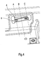
- einen Antennenverbindungsstecker im Gewichtsreduzierungsloch, teilweise hinter der vom Gewichtsreduzierungsloch aufgespannten Lochfläche positioniert.
- Figuren 5,6,7
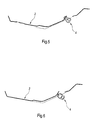
- Schnitte durch den Antennenverbindungsstecker der Figur 4.
- Figur 1 zeigt das am hinteren Dachrahmen 1 eines Personenkraftfahrzeugs befestigte Verstärkungsblech 2. Von der nicht dargestellten Dachantenne kommt ein Antennenkabel 3 der Kabellänge 270 mm. Abschlusseitig besitzt das Antennenkabel 3 einen Antennenverbindungsstecker 4 um es mit dem Bordkabelnetz zu verbinden.
- Der Antennenverbindungsstecker 4 befindet hinter einem mit einer Abkantung 5 versehenen Gewichtsreduzierungsloch 6. Der Antennenverbindungsstecker 4 ist hierbei so positioniert, dass er teilweise unterhalb der Oberfläche 7 des Verstärkungsblechs 2 zu liegen kommt. Mehr Kopffreiheit lässt sich gewinnen, wenn eine vollständige Integration des Antennensteckers in die Struktur realisiert wird.
- Das Gewichtsreduzierungsloch 6 hat prinzipiell eine beliebige Form. Zwecks Realisierung einer maximalen Kopffreiheit wird es bevorzugt so groß gewählt, dass der komplette Antennenverbindungsstecker versenkt platziert werden kann. Im vorliegenden Beispiel ist das Gewichtsreduzierungsloch 6 rechteckigen Zuschnitts und hat Abmessungen von ca. (110 x 40) mm. Beim Ausstanzen des Gewichtsreduzierungslochs 6 verblieb ein Teil seiner Fläche der nun als Halter 8 dient. Der Halter 8 besitzt eine Aussparung 9, in der der Antennenverbindungsstecker 4 einrasten kann.
- Figur 2 zeigt den Einbaubereich des Antennenverbindungs-steckers 4 ohne Einsatz der Erfindung und ohne örtlich optimierten Formhimmelträger, und zwar als Schnitt senkrecht zur besagten Oberfläche 7 des Verstärkungsblechs 2. Im Bereich des Wasserkanals 10 der Heckklappe bzw. am hinteren Dachrahmen 1 befindet sich das Verstärkungsblech 11. Auf dem Verstärkungsblech 2 befindet fahrrauminnenseitig der Antennenverbindungsstecker 4.
- Sitzt eine Person in der hintersten Sitzreihe und sieht in Fahrtrichtung, so definiert seine Kopfoberfläche bei einer Nickbewegung die Kopflinien 11 und 12. Die Kopflinie 11 beschreibt die Kontur des Kopfes, wohingegen die Kopflinie 12 die Schwinglinie des Kopfes bei einer Nickbewegung wiedergibt. Für einen hohen Fahrkomfort sollte der Kopf dieser Person einen genügenden Abstand vom Formhimmel 13 des Fahrzeuginnenraums haben. Die Linie 14 gibt die Linie des geforderten Kopfraumes wieder, und die Linie 15 eine theoretische Formhimmellinie ohne Antennenkabeleinfluss.
- Der Formhimmel 13 ist eine Strecke s vom Antennenverbindungsstecker 4 beabstandet. Die Strecke s beträgt im Beispiel etwa 12 mm bis 15 mm. Eine Realisierung der gewünschten Kopffreiheit, durch die Soll-Kopflinie 14 definiert, ist nach dem Stand der Technik nicht möglich. Grund ist, dass der Antennenverbindungsstecker 4 in den Fahrzeuginnenraum hineinragt.
- Figur 3 zeigt den zu Figur 2 entsprechenden Einbaubereich desselben Fahrzeugmodells von Figur 2 unter Einsatz der Erfindung. Der Antennenstecker 4 befindet sich nun teilweise im Gewichtsreduzierungsloch 6 und ist damit weiter vom Formhimmel 13 entfernt. Damit lässt sich bei der Fahrzeugentwicklung der Formhimmel 13 in Richtung des Verstärkungsblechs 2 verlegen. Dies hat zur Folge hat, dass die Formhimmelfläche fahrzeuginnenseitig weiter nach hinten verschoben werden kann und dadurch die Kopffreiheit vergrößert wird. Des weiteren wird der Formhimmelträger örtlich im Bereich des Antennenverbindungssteckers auf ein Minimum verpresst. Die sich damit einstellende Änderung der Strecke s um 2-4 mm vergrößert die Kopffreiheit einer Person in der hintersten Sitzreihe zusätzlich und erhöht den Fahrkomfort noch weiter.
- Die mit der Erfindung realisierte Formhimmellinie 13 ist in Figur 3 eingezeichnet und veranschaulicht durch den Abstand der Linien 13 und 14 den Gewinn an Kopffreiheit.
- Die erhöhte Kopffreiheit in der hintersten Sitzreihe wird erzielt, ohne dass der Formhimmel 13 nebst Dach konstruktiv aufwendig angehoben werden müsste. Der konstruktive Aufwand zur Verbesserung der Kopffreiheit ist damit minimal. Gleichzeitig hat der Fahrer eine unveränderte freie Sicht nach hinten.
- Selbstverständlich ist es bei als ausreichend erachteter Kopffreiheit, z.B. bei einem relativ hoch gebautem Dach, auch möglich, die Erfindung dahingehend zu nutzen, dass die Kopffreiheit unverändert bleibt und das Dach mit dem hinteren Dachrahmen weiter nach unten gezogen wird. Das Fahrzeug wird dadurch flacher, der Fahrwiderstand kleiner und der Kraftstoffverbrauch sinkt, ohne dass die Fahrer eine verschlechterte Sicht nach hinten durch einen abgesenkten Formhimmel hätte.
- Figur 4 zeigt ausschnittsweise ein dem Dachrahmen 1 zugeordneten Verstärkungsblech 2 mit einem Gewichtsreduzierungsloch 6. Im Gewichtsreduzierungsloch 6 befindet sich der Antennenverbindungssstecker 4.
- Zur Veranschaulichung der Position des Antennenverbindungssteckers 4 in Relation zu der durch das Gewichtsreduzierungsloch aufgespannten Ebene dienen die Figuren 5,6, und 7. Sie zeigen nacheinander die drei Schnitte C, B und A senkrecht zur (Verstärkungs-) Blechfläche. In den drei Figuren 5,6 und 7 ist der oberhalb des Verstärkungsblechs 2 dem Außenbereich zugewandt, und ist also der Bereich unterhalb des Verstärkungsblechs 2 dem Fahrzeuginneren zugewandt. Man erkennt in allen drei Figuren, dass der Antennenverbindungsstecker bezogen auf die Blechfläche teilweise hinter der durch das Gewichtsreduzierungsloch aufgespannten Fläche zu liegen kommt. Er ragt also weniger in den Fahrzeuginnenraum hinein was zu einem Mehr an Kopffreiheit führt.
-
- 01
- hinterer Dachrahmen
- 02
- Verstärkungsblech
- 03
- Antennenkabel
- 04
- Antennenverbindungsstecker
- 05
- Abkantung
- 06
- Gewichtsreduzierungsloch
- 07
- Oberfläche
- 08
- Halter
- 09
- Aussparung
- 10
- Wasserkanal
- 11
- Konturlinie Kopf
- 12
- Schwinglinie des Kopfes
- 13
- Formhimmel
- 14
- Linie geforderter Kopfraum
- 15
- theoretische Formhimmellinie ohne Antennenkabeleinfluss
Claims (4)
- Kraftfahrzeug mit einem Gewichtsreduzierungsloch (6) im hinteren Dachrahmen oder in einem dem hinteren Dachrahmen zugeordneten Verstärkungsblech, und mit einem Antennenverbindungsstecker (4), der, bezogen auf eine Richtung entgegengesetzt zur Fahrtzeuglängsrichtung, zumindest teilweise hinter der durch das Gewichtsreduzierungsloch aufgespannten Fläche angeordnet ist.
- Kraftfahrzeug nach Anspruch 1,
dadurch gekennzeichnet,
dass das Gewichtsreduzierungsloch in einem Abstand von etwa 100 mm bis etwa 150 mm, gerechnet von der Mitte des Fahrzeugs in Fahrzeugquerrichtung, angeordnet ist. - Kraftfahrzeug nach Anspruch 1,
dadurch gekennzeichnet,
dass der Rand des Gewichtsreduzierungslochs zumindest teilweise abgekantet ist. - Kraftfahrzeug nach Anspruch 1,
dadurch gekennzeichnet,
dass für den Antennenverbindungsstecker ein mit dem Verstärkungsblech einstückig ausgebildeter Halter (8) vorgesehen ist.
Applications Claiming Priority (1)
| Application Number | Priority Date | Filing Date | Title |
|---|---|---|---|
| DE102005050256A DE102005050256A1 (de) | 2005-10-20 | 2005-10-20 | Kraftfahrzeug mit optimal positioniertem Antennenverbindungsstecker |
Publications (2)
| Publication Number | Publication Date |
|---|---|
| EP1777112A1 true EP1777112A1 (de) | 2007-04-25 |
| EP1777112B1 EP1777112B1 (de) | 2008-10-15 |
Family
ID=37314826
Family Applications (1)
| Application Number | Title | Priority Date | Filing Date |
|---|---|---|---|
| EP06021786A Not-in-force EP1777112B1 (de) | 2005-10-20 | 2006-10-18 | Kraftfahrzeug mit optimal positioniertem Antennenverbindungsstecker |
Country Status (3)
| Country | Link |
|---|---|
| EP (1) | EP1777112B1 (de) |
| AT (1) | ATE411201T1 (de) |
| DE (2) | DE102005050256A1 (de) |
Families Citing this family (1)
| Publication number | Priority date | Publication date | Assignee | Title |
|---|---|---|---|---|
| DE102013222951A1 (de) | 2013-11-12 | 2015-05-13 | Bayerische Motoren Werke Aktiengesellschaft | Antennenbaugruppe für ein Kraftfahrzeug und Kraftfahrzeug mit der Antennenbaugruppe |
Citations (6)
| Publication number | Priority date | Publication date | Assignee | Title |
|---|---|---|---|---|
| JPS60166569A (ja) * | 1984-02-10 | 1985-08-29 | Nissan Motor Co Ltd | 自動車の車体構造 |
| EP0181765A1 (de) * | 1984-11-06 | 1986-05-21 | Toyota Jidosha Kabushiki Kaisha | Kraftfahrzeugantennensystem |
| EP0182614A1 (de) * | 1984-11-15 | 1986-05-28 | Toyota Jidosha Kabushiki Kaisha | Kraftfahrzeugantennensystem |
| EP0183521A1 (de) * | 1984-11-27 | 1986-06-04 | Toyota Jidosha Kabushiki Kaisha | Kraftfahrzeugantennensystem |
| EP0196209A2 (de) * | 1985-03-27 | 1986-10-01 | Toyota Jidosha Kabushiki Kaisha | Fahrzeugantennensystem |
| JPS6215146A (ja) * | 1985-07-12 | 1987-01-23 | Nissan Motor Co Ltd | ル−フアンテナの取付け構造 |
-
2005
- 2005-10-20 DE DE102005050256A patent/DE102005050256A1/de not_active Withdrawn
-
2006
- 2006-10-18 AT AT06021786T patent/ATE411201T1/de not_active IP Right Cessation
- 2006-10-18 DE DE502006001814T patent/DE502006001814D1/de active Active
- 2006-10-18 EP EP06021786A patent/EP1777112B1/de not_active Not-in-force
Patent Citations (6)
| Publication number | Priority date | Publication date | Assignee | Title |
|---|---|---|---|---|
| JPS60166569A (ja) * | 1984-02-10 | 1985-08-29 | Nissan Motor Co Ltd | 自動車の車体構造 |
| EP0181765A1 (de) * | 1984-11-06 | 1986-05-21 | Toyota Jidosha Kabushiki Kaisha | Kraftfahrzeugantennensystem |
| EP0182614A1 (de) * | 1984-11-15 | 1986-05-28 | Toyota Jidosha Kabushiki Kaisha | Kraftfahrzeugantennensystem |
| EP0183521A1 (de) * | 1984-11-27 | 1986-06-04 | Toyota Jidosha Kabushiki Kaisha | Kraftfahrzeugantennensystem |
| EP0196209A2 (de) * | 1985-03-27 | 1986-10-01 | Toyota Jidosha Kabushiki Kaisha | Fahrzeugantennensystem |
| JPS6215146A (ja) * | 1985-07-12 | 1987-01-23 | Nissan Motor Co Ltd | ル−フアンテナの取付け構造 |
Also Published As
| Publication number | Publication date |
|---|---|
| DE502006001814D1 (de) | 2008-11-27 |
| DE102005050256A1 (de) | 2007-05-16 |
| ATE411201T1 (de) | 2008-10-15 |
| EP1777112B1 (de) | 2008-10-15 |
Similar Documents
| Publication | Publication Date | Title |
|---|---|---|
| DE10219764B4 (de) | Klappbare Fahrzeugbordwand mit daran befestigten Sitzkomponenten | |
| DE102017002249B4 (de) | Kraftfahrzeug und Fahrzeugkarosserie für ein Kraftfahrzeug | |
| DE10063770B4 (de) | Windschutzvorrichtung für ein Kraftfahrzeug | |
| EP3194215B1 (de) | Baukastensystem für ein fahrzeug | |
| EP3617040A1 (de) | Fahrerhausfrontmodul und verfahren zur herstellung eines fahrerhauses | |
| EP3484735A1 (de) | Verfahren zum herstellen eines fahrzeugdachs, moduldach für ein fahrzeugdach und fahrzeugdach für ein kraftfahrzeug | |
| DE202024100479U1 (de) | Zweistufige synchronisierte pneumatische Wendepedalvorrichtung und Fahrzeug | |
| DE102009047690A1 (de) | Fahrzeuglenkrad | |
| DE10039791B4 (de) | Cabriolet | |
| EP1698511B1 (de) | System zur automatischen Sitzkonturverstellung, sowie Sitz mit derartigem System | |
| DE102005019917B4 (de) | Dachverstauvorrichtung für Fahrzeuge | |
| DE102014014541A1 (de) | Verfahren und Anordnung zur Justierung einer Türinnenverkleidung an einem Kraftfahrzeug | |
| EP1777112B1 (de) | Kraftfahrzeug mit optimal positioniertem Antennenverbindungsstecker | |
| DE19923737B4 (de) | Mehrteilige Stirnwand für eine Kraftfahrzeugrohbaukarosserie | |
| DE60311717T2 (de) | Schiebedachanordnung für ein Fahrzeug | |
| WO2019110333A1 (de) | Verkleidungselement zur verkleidung einer seitenfläche eines fahrzeuginnenraums sowie fahrzeug | |
| DE102016107329B4 (de) | Fahrzeugairbag mit aktiver Entlüftung | |
| DE8119662U1 (de) | Entlüftungsdach für Kraftfahrzeuge | |
| DE102014003422B4 (de) | Vorrichtung zur Befestigung eines Gassackmoduls in einem Kraftfahrzeug, Lenkrad, Lenkradbaugruppe sowie Verfahren zur Herstellung einer Lenkradbaugruppe | |
| EP1769956A1 (de) | Heckklappe eines Kraftfahrzeugs | |
| DE102012004955A1 (de) | Halteanordnung eines Kühlmoduls an einem Aufbauelement eines Kraftwagenaufbaus | |
| EP2790940B1 (de) | Halteanordnung eines flügelelements, insbesondere einer haube, einer klappe oder dergleichen, und eines verkleidungselements an einem kraftwagenaufbau | |
| DE4415468C1 (de) | Befestigungsanordnung für eine Abdeckung eines aufblasbaren Gassacks von Fahrzeugen | |
| DE102018103689A1 (de) | Sitzanordnung mit integriertem Kopfstützenmotor | |
| DE102013212579B4 (de) | Mittelarmlehne für einen Fahrzeuginnenraum eines Kraftfahrzeugs |
Legal Events
| Date | Code | Title | Description |
|---|---|---|---|
| PUAI | Public reference made under article 153(3) epc to a published international application that has entered the european phase |
Free format text: ORIGINAL CODE: 0009012 |
|
| AK | Designated contracting states |
Kind code of ref document: A1 Designated state(s): AT BE BG CH CY CZ DE DK EE ES FI FR GB GR HU IE IS IT LI LT LU LV MC NL PL PT RO SE SI SK TR |
|
| AX | Request for extension of the european patent |
Extension state: AL BA HR MK YU |
|
| 17P | Request for examination filed |
Effective date: 20071025 |
|
| AKX | Designation fees paid |
Designated state(s): AT BE BG CH CY CZ DE DK EE ES FI FR GB GR HU IE IS IT LI LT LU LV MC NL PL PT RO SE SI SK TR |
|
| GRAP | Despatch of communication of intention to grant a patent |
Free format text: ORIGINAL CODE: EPIDOSNIGR1 |
|
| GRAS | Grant fee paid |
Free format text: ORIGINAL CODE: EPIDOSNIGR3 |
|
| GRAA | (expected) grant |
Free format text: ORIGINAL CODE: 0009210 |
|
| AK | Designated contracting states |
Kind code of ref document: B1 Designated state(s): AT BE BG CH CY CZ DE DK EE ES FI FR GB GR HU IE IS IT LI LT LU LV MC NL PL PT RO SE SI SK TR |
|
| REG | Reference to a national code |
Ref country code: CH Ref legal event code: EP Ref country code: GB Ref legal event code: FG4D Free format text: NOT ENGLISH |
|
| REG | Reference to a national code |
Ref country code: IE Ref legal event code: FG4D Free format text: LANGUAGE OF EP DOCUMENT: GERMAN |
|
| REF | Corresponds to: |
Ref document number: 502006001814 Country of ref document: DE Date of ref document: 20081127 Kind code of ref document: P |
|
| NLV1 | Nl: lapsed or annulled due to failure to fulfill the requirements of art. 29p and 29m of the patents act | ||
| REG | Reference to a national code |
Ref country code: GB Ref legal event code: 732E Free format text: REGISTERED BETWEEN 20090305 AND 20090311 |
|
| BERE | Be: lapsed |
Owner name: GM GLOBAL TECHNOLOGY OPERATIONS, INC. Effective date: 20081031 |
|
| PG25 | Lapsed in a contracting state [announced via postgrant information from national office to epo] |
Ref country code: BG Free format text: LAPSE BECAUSE OF FAILURE TO SUBMIT A TRANSLATION OF THE DESCRIPTION OR TO PAY THE FEE WITHIN THE PRESCRIBED TIME-LIMIT Effective date: 20090115 Ref country code: ES Free format text: LAPSE BECAUSE OF FAILURE TO SUBMIT A TRANSLATION OF THE DESCRIPTION OR TO PAY THE FEE WITHIN THE PRESCRIBED TIME-LIMIT Effective date: 20090126 Ref country code: LT Free format text: LAPSE BECAUSE OF FAILURE TO SUBMIT A TRANSLATION OF THE DESCRIPTION OR TO PAY THE FEE WITHIN THE PRESCRIBED TIME-LIMIT Effective date: 20081015 |
|
| PG25 | Lapsed in a contracting state [announced via postgrant information from national office to epo] |
Ref country code: SI Free format text: LAPSE BECAUSE OF FAILURE TO SUBMIT A TRANSLATION OF THE DESCRIPTION OR TO PAY THE FEE WITHIN THE PRESCRIBED TIME-LIMIT Effective date: 20081015 Ref country code: LV Free format text: LAPSE BECAUSE OF FAILURE TO SUBMIT A TRANSLATION OF THE DESCRIPTION OR TO PAY THE FEE WITHIN THE PRESCRIBED TIME-LIMIT Effective date: 20081015 Ref country code: PT Free format text: LAPSE BECAUSE OF FAILURE TO SUBMIT A TRANSLATION OF THE DESCRIPTION OR TO PAY THE FEE WITHIN THE PRESCRIBED TIME-LIMIT Effective date: 20090316 Ref country code: FI Free format text: LAPSE BECAUSE OF FAILURE TO SUBMIT A TRANSLATION OF THE DESCRIPTION OR TO PAY THE FEE WITHIN THE PRESCRIBED TIME-LIMIT Effective date: 20081015 Ref country code: NL Free format text: LAPSE BECAUSE OF FAILURE TO SUBMIT A TRANSLATION OF THE DESCRIPTION OR TO PAY THE FEE WITHIN THE PRESCRIBED TIME-LIMIT Effective date: 20081015 Ref country code: IS Free format text: LAPSE BECAUSE OF FAILURE TO SUBMIT A TRANSLATION OF THE DESCRIPTION OR TO PAY THE FEE WITHIN THE PRESCRIBED TIME-LIMIT Effective date: 20090215 Ref country code: PL Free format text: LAPSE BECAUSE OF FAILURE TO SUBMIT A TRANSLATION OF THE DESCRIPTION OR TO PAY THE FEE WITHIN THE PRESCRIBED TIME-LIMIT Effective date: 20081015 Ref country code: MC Free format text: LAPSE BECAUSE OF NON-PAYMENT OF DUE FEES Effective date: 20081031 |
|
| REG | Reference to a national code |
Ref country code: IE Ref legal event code: FD4D |
|
| PG25 | Lapsed in a contracting state [announced via postgrant information from national office to epo] |
Ref country code: EE Free format text: LAPSE BECAUSE OF FAILURE TO SUBMIT A TRANSLATION OF THE DESCRIPTION OR TO PAY THE FEE WITHIN THE PRESCRIBED TIME-LIMIT Effective date: 20081015 Ref country code: RO Free format text: LAPSE BECAUSE OF FAILURE TO SUBMIT A TRANSLATION OF THE DESCRIPTION OR TO PAY THE FEE WITHIN THE PRESCRIBED TIME-LIMIT Effective date: 20081015 Ref country code: DK Free format text: LAPSE BECAUSE OF FAILURE TO SUBMIT A TRANSLATION OF THE DESCRIPTION OR TO PAY THE FEE WITHIN THE PRESCRIBED TIME-LIMIT Effective date: 20081015 Ref country code: IE Free format text: LAPSE BECAUSE OF FAILURE TO SUBMIT A TRANSLATION OF THE DESCRIPTION OR TO PAY THE FEE WITHIN THE PRESCRIBED TIME-LIMIT Effective date: 20081015 |
|
| PLBE | No opposition filed within time limit |
Free format text: ORIGINAL CODE: 0009261 |
|
| STAA | Information on the status of an ep patent application or granted ep patent |
Free format text: STATUS: NO OPPOSITION FILED WITHIN TIME LIMIT |
|
| PG25 | Lapsed in a contracting state [announced via postgrant information from national office to epo] |
Ref country code: SE Free format text: LAPSE BECAUSE OF FAILURE TO SUBMIT A TRANSLATION OF THE DESCRIPTION OR TO PAY THE FEE WITHIN THE PRESCRIBED TIME-LIMIT Effective date: 20090115 Ref country code: CZ Free format text: LAPSE BECAUSE OF FAILURE TO SUBMIT A TRANSLATION OF THE DESCRIPTION OR TO PAY THE FEE WITHIN THE PRESCRIBED TIME-LIMIT Effective date: 20081015 Ref country code: IT Free format text: LAPSE BECAUSE OF FAILURE TO SUBMIT A TRANSLATION OF THE DESCRIPTION OR TO PAY THE FEE WITHIN THE PRESCRIBED TIME-LIMIT Effective date: 20081015 |
|
| 26N | No opposition filed |
Effective date: 20090716 |
|
| PG25 | Lapsed in a contracting state [announced via postgrant information from national office to epo] |
Ref country code: SK Free format text: LAPSE BECAUSE OF FAILURE TO SUBMIT A TRANSLATION OF THE DESCRIPTION OR TO PAY THE FEE WITHIN THE PRESCRIBED TIME-LIMIT Effective date: 20081015 Ref country code: BE Free format text: LAPSE BECAUSE OF NON-PAYMENT OF DUE FEES Effective date: 20081031 |
|
| REG | Reference to a national code |
Ref country code: FR Ref legal event code: ST Effective date: 20090831 |
|
| REG | Reference to a national code |
Ref country code: GB Ref legal event code: 732E Free format text: REGISTERED BETWEEN 20091029 AND 20091104 |
|
| REG | Reference to a national code |
Ref country code: GB Ref legal event code: 732E Free format text: REGISTERED BETWEEN 20091105 AND 20091111 |
|
| PG25 | Lapsed in a contracting state [announced via postgrant information from national office to epo] |
Ref country code: AT Free format text: LAPSE BECAUSE OF NON-PAYMENT OF DUE FEES Effective date: 20081018 |
|
| PG25 | Lapsed in a contracting state [announced via postgrant information from national office to epo] |
Ref country code: LU Free format text: LAPSE BECAUSE OF NON-PAYMENT OF DUE FEES Effective date: 20081018 Ref country code: CY Free format text: LAPSE BECAUSE OF FAILURE TO SUBMIT A TRANSLATION OF THE DESCRIPTION OR TO PAY THE FEE WITHIN THE PRESCRIBED TIME-LIMIT Effective date: 20081015 Ref country code: HU Free format text: LAPSE BECAUSE OF FAILURE TO SUBMIT A TRANSLATION OF THE DESCRIPTION OR TO PAY THE FEE WITHIN THE PRESCRIBED TIME-LIMIT Effective date: 20090416 |
|
| PG25 | Lapsed in a contracting state [announced via postgrant information from national office to epo] |
Ref country code: TR Free format text: LAPSE BECAUSE OF FAILURE TO SUBMIT A TRANSLATION OF THE DESCRIPTION OR TO PAY THE FEE WITHIN THE PRESCRIBED TIME-LIMIT Effective date: 20081015 |
|
| PG25 | Lapsed in a contracting state [announced via postgrant information from national office to epo] |
Ref country code: GR Free format text: LAPSE BECAUSE OF FAILURE TO SUBMIT A TRANSLATION OF THE DESCRIPTION OR TO PAY THE FEE WITHIN THE PRESCRIBED TIME-LIMIT Effective date: 20090116 |
|
| REG | Reference to a national code |
Ref country code: DE Ref legal event code: R081 Ref document number: 502006001814 Country of ref document: DE Owner name: GM GLOBAL TECHNOLOGY OPERATIONS LLC (N. D. GES, US Free format text: FORMER OWNER: GM GLOBAL TECHNOLOGY OPERATIONS, INC., DETROIT, MICH., US Effective date: 20110323 |
|
| REG | Reference to a national code |
Ref country code: CH Ref legal event code: PL |
|
| PG25 | Lapsed in a contracting state [announced via postgrant information from national office to epo] |
Ref country code: LI Free format text: LAPSE BECAUSE OF NON-PAYMENT OF DUE FEES Effective date: 20101031 Ref country code: CH Free format text: LAPSE BECAUSE OF NON-PAYMENT OF DUE FEES Effective date: 20101031 |
|
| PGFP | Annual fee paid to national office [announced via postgrant information from national office to epo] |
Ref country code: DE Payment date: 20121010 Year of fee payment: 7 |
|
| REG | Reference to a national code |
Ref country code: DE Ref legal event code: R119 Ref document number: 502006001814 Country of ref document: DE Effective date: 20140501 |
|
| PG25 | Lapsed in a contracting state [announced via postgrant information from national office to epo] |
Ref country code: DE Free format text: LAPSE BECAUSE OF NON-PAYMENT OF DUE FEES Effective date: 20140501 |
|
| PGFP | Annual fee paid to national office [announced via postgrant information from national office to epo] |
Ref country code: GB Payment date: 20151014 Year of fee payment: 10 |
|
| PG25 | Lapsed in a contracting state [announced via postgrant information from national office to epo] |
Ref country code: FR Free format text: LAPSE BECAUSE OF NON-PAYMENT OF DUE FEES Effective date: 20081031 |
|
| GBPC | Gb: european patent ceased through non-payment of renewal fee |
Effective date: 20161018 |
|
| PG25 | Lapsed in a contracting state [announced via postgrant information from national office to epo] |
Ref country code: GB Free format text: LAPSE BECAUSE OF NON-PAYMENT OF DUE FEES Effective date: 20161018 |