EP1777012A2 - Elektrische Nassreinigungsvorrichtung - Google Patents
Elektrische Nassreinigungsvorrichtung Download PDFInfo
- Publication number
- EP1777012A2 EP1777012A2 EP06255482A EP06255482A EP1777012A2 EP 1777012 A2 EP1777012 A2 EP 1777012A2 EP 06255482 A EP06255482 A EP 06255482A EP 06255482 A EP06255482 A EP 06255482A EP 1777012 A2 EP1777012 A2 EP 1777012A2
- Authority
- EP
- European Patent Office
- Prior art keywords
- liquid tank
- cleaning apparatus
- wet
- type electric
- air
- Prior art date
- Legal status (The legal status is an assumption and is not a legal conclusion. Google has not performed a legal analysis and makes no representation as to the accuracy of the status listed.)
- Withdrawn
Links
Images


Classifications
-
- B—PERFORMING OPERATIONS; TRANSPORTING
- B03—SEPARATION OF SOLID MATERIALS USING LIQUIDS OR USING PNEUMATIC TABLES OR JIGS; MAGNETIC OR ELECTROSTATIC SEPARATION OF SOLID MATERIALS FROM SOLID MATERIALS OR FLUIDS; SEPARATION BY HIGH-VOLTAGE ELECTRIC FIELDS
- B03C—MAGNETIC OR ELECTROSTATIC SEPARATION OF SOLID MATERIALS FROM SOLID MATERIALS OR FLUIDS; SEPARATION BY HIGH-VOLTAGE ELECTRIC FIELDS
- B03C3/00—Separating dispersed particles from gases or vapour, e.g. air, by electrostatic effect
- B03C3/02—Plant or installations having external electricity supply
- B03C3/16—Plant or installations having external electricity supply wet type
Definitions
- the present invention relates to a wet-type electric cleaning apparatus for removing dust by passing outside air that contains dust through a liquid stored inside the liquid tank.
- the pressure inside the upper space in the liquid tank is reduced by an exhaust pump; however, when the amount of water droplets contained in the air in that upper space becomes large, water tends to be taken into the exhaust pump, so that the exhaust pump will be damaged, and moisture will be contained in the exhaust air that is exhausted from the exhaust pump to the outside, which is undesirable.
- Japanese Utility Model Application Publication (Kokoku) No. 63-12839 discloses an apparatus in which a substantially cup-shaped moisture separator (turning separator) that turns at high speed is provided in the upper space inside a water tank, and the air inside the water tank (air containing water droplets) is conducted through a slit provided in the moisture separator to the inside thereof and conducted to an exhaust pump. With that slit, the water droplets are separated by centrifugal force and returned to the water tank.
- a substantially cup-shaped moisture separator turning separator
- Japanese Patent Application Publication (Kokoku) No. 6-104098 and Japanese Patent Application Laid-Open (Kokai) No. 4-92636 disclose apparatuses in which outside air that contains dust is directed toward and made to flow into the upper space inside a cylindrical water tank, and the dust is captured in the water by causing the dust to vigorously contact the water surface. In these apparatuses, air is discharged from the center of the upper space of the water tank.
- Japanese Patent Nos. 2701132 , 2701129 , and 2772754 outside air that contains dust is made to flow into water from the inner circumference surface inside the water tank toward the swirling direction.
- Japanese Patent No. 2701132 and 2701129 disclose cylinders of differing radius that are combined from above and below to form a maze (bending air passage), so that water is separated.
- outside air that contains dust is caused to flow in along the inner circumference surface of the water tank, and air is discharged from the center of the water tank.
- outside air is conducted into water from an outer cylinder which is advanced in the water from the vicinity of the center of the water tank (in Japanese Utility Model Application Publication (Kokoku). No. S53-23982 ) or from a fan-shaped open part (in Japanese Patent Application Laid-Open (Kokai) No. 10-128033 ), and the outside air passed through that water is made to detour around the lower edge of such fan-shaped open part or outer cylinder on the outside thereof in the radial direction as it is conducted to the upper space in the water tank.
- the present invention is made in view of such circumstances as described above.
- the outside air that contains dust is conducted in the swirl direction from the vicinity of the central bottom inside the liquid tank, and the outside air discharged from the discharge port is conducted to the under surface of the guide panel and whirls while being vigorously mixed with the liquid. Accordingly, the mixed flow of the outside air and liquid move in the outer peripheral direction of the guide panel due to centrifugal force, and dust is captured in the liquid during this move of the mixed flow; and further, lighter air flows into the upper space inside the liquid tank, while whirling, through the ring-shaped gap that is between the outer peripheral edge of the guide panel and the inner circumferential surface of the liquid tank.
- the intake passage be bent in the vicinity of the upper center of the liquid tank so as to cause the outside air inducted from one side of an upper part of the liquid tank to descend substantially vertically in the vicinity of the center of the liquid tank, thus conducting the inducted air to below the center of the guide panel.
- the reason for this structure taken is that since the intake passage is provided in the center inside the liquid tank, it does not impede the swirling flow motion of the mixed flow or the swirling flow motion of the air in the upper space.
- the exhaust passage is provided with an exhaust port adjacent to and in the radial direction with respect to the intake passage so that the exhaust port opens in the upper space inside the liquid tank.
- the air is exhausted without disturbing the swirling motion of air generated on the outside of the intake passage.
- an exhaust space of as large a capacity as possible be continuously formed to the exhaust port, so that the swirling motion of the air flowing in from the upper space is not disturbed.
- a swirling flow channel be provided for allowing the outside air discharged from the discharge port to make a swirling flow, because this structure makes it possible to impart a strong swirl motion to the mixed flow of the outside air and the liquid.
- the guide panel is inclined so as to be gradually higher from the discharge port side into a direction of swirling flow of the outside air discharged from the discharge port.
- the reason for this is that the mixed flow can be conducted from the vicinity of the discharge port to the under surface of the guide panel, while whirling, so that the swirling flow motion can be strengthened while the mixed flow rises along the incline of the under surface of the guide panel (that is, while using the force of floatation).
- the radius of the guide panel gradually decrease from the discharge port side into a direction of swirling flow of the outside air discharged from the discharge port.
- the ring-shaped gap formed between the outer peripheral edge of the guide panel and the inner circumferential surface of the liquid tank gradually increases from the discharge port side along the swirling direction of the mixed flow, and thus it is possible to augment and strengthen the whirling of the air flowing into the upper space through the ring-shaped gap.
- a baffle(s) for removing liquid droplets from the swirling air flow inside the liquid tank be provided, so that it is located more to the outer peripheral side than the exhaust port.
- the baffle can be of a cylindrical shape and extends down from the upper part (exhaust space) of the liquid tank between the exhaust port and the inner circumferential surface of the liquid tank.
- a dry filter be provided on the liquid tank, so that the exhausting air pass through this filter.
- the reason for this structure is that should any liquid droplets or very fine dust nevertheless be contained in the exhaust air, they can be removed by this filter.
- the reference numeral 10 designates a water tank.
- the water tank 10 comprises a cylindrical main tank unit 12 having a closed bottom, an inner member 14 mounted at the opening of the main tank unit 12, and a cover 16.
- the inner member 14 has an upper disk unit 18 that engages the edge of the opening of the main tank unit 12 from above, and the circumferential edge of the upper disk unit 18 is clamped so as to be airtight by packings 20 between the cover 16 and the edge of the opening of the main tank unit 12.
- the upper disk unit 18 of the inner member 14 has a circular shape when viewed from above.
- a cylindrical part 22 protrudes vertically downward.
- a swirling flow channel 24 is formed which, while describing a spiral in the horizontal plane, opens toward substantially a tangential direction. The opening of this swirling flow channel 24 at the bottom makes the discharge port 26 of an intake passage 32 that will be described below.
- an intake tube 28 is inserted from above.
- This intake tube 28 is a tube having a circular cross-section, and it is bent at substantially a right angle so that one end of the intake tube 28 extends substantially horizontal toward the direction of the side of a space (exhaust space) 30 between the upper disk unit 18 and the cover 16, and the other end of the intake tube 28 advances inside the cylindrical part 22. Airtightness is maintained between the intake tube 28 and the inner surface of the cylindrical part 22.
- the intake passage 32 (see Fig. 4) is formed that conducts the outside air, which contains dust, to the discharge port 26.
- a suction tool (not shown in the drawings) is connected via a flexible connecting tube (not shown), and the outside air that contains dust is conducted from the suction tool and into the main tank unit 12 through the intake passage 32.
- a guide panel 34 that covers over the discharge port 26 in the shape of a canopy is integrally formed.
- This guide panel 34 is substantially disc-shaped, and it is inclined as seen from Fig. 4 so that the discharge port 26 side is low and it gradually becomes higher along the direction of opening of the discharge port 26 (or in the direction of the swirling motion of the mixed flow described below).
- water is introduced to a height that substantially submerge that guide panel 34 or to a height immediately below the under surface of the guide panel 34.
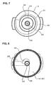
- the guide panel 34 furthermore, forms, as best seen from Fig. 6, a gap (ring-shaped gap) 36 that is ring-shaped when viewed from above, with the outer peripheral edge thereof and the inner circumferential surface of the main tank unit 12.
- the radius of the guide panel 34, as shown in Fig. 6, is large on the discharge port 26 side, and it becomes gradually smaller along the direction of the opening of the discharge port 26 or in the direction of the swirling motion of the mixed flow (in other words, the radius becomes smaller the discharge port 26 side in the counterclockwise direction in Fig. 6).
- the ring-shaped gap 36 is narrow on the discharge port 26 side and it becomes gradually larger in conjunction with the turning in the direction of the opening of the discharge port 26 or in the direction of the swirling motion of the mixed flow (in other words, the ring-shaped gap 36 becomes larger the discharge port 26 side in the counterclockwise direction in Fig. 6).
- a bottom panel 38 is provided at the lower end of the cylindrical part 22 at the lower end of the cylindrical part 22.
- This bottom panel 38 gradually increases the cross-sectional area of the swirling flow channel 24 in the downstream direction by gradually lowering the bottom surface of the swirling flow channel 24 in the direction of the swirling motion of the mixed flow.
- the bottom panel 38 is a cylinder with its height gradually decreases the discharge port 26 side in the counterclockwise direction in Fig. 5
- the upper disk unit 18 of the inner member 14 is formed with an exhaust port 40 adjacent to the outside in the radial direction of the cylindrical part 22.
- This exhaust port 40 is substantially arc shaped and partially surrounds the cylindrical part 22 as illustrated in Fig. 8, and it connects the upper space 42 inside the water tank 10 to the exhaust space 30 which is between the inner member 14 and the cover 16.
- baffle elements 44 and 46 are formed on the under surface of the upper disk unit 18, as seen from Figs. 3 and 4, two baffle elements or baffles 44 and 46 are formed.
- the baffles 44 and 46 are in a cylindrical shape and concentric with the cylindrical part 22.
- the lower edge of the inside baffle panel 44 is horizontal, while the outside baffle panel 46 is smaller in the vertical direction than the inside baffle panel 44, and the lower edge thereof is formed in a spiral shape so as to become, as can be seen by comparing Figs. 3 and 4, gradually higher along the direction of the swirling motion of the air inside the upper space 42.
- the above-described exhaust port 40 is located between the cylindrical part 22 and the inside baffle panel 44. In the structure described above, the exhaust space 30 and the exhaust port 40 form an exhaust passage.
- a ring-shaped rib 50 is made to protrude along the edge of the circular opening 48 of the cover 16, and a dry filter 52 is provided in the ring-shaped rib 50.
- an exhaust pump 54 (Fig. 4) is attached so as to be in connection with the dry filter 52.
- the exhaust pump 54 when a fan (not shown) is rotated by an electric motor, exhausts the interior of the exhaust space 30 and the upper space 42 inside the water tank 10 communicating therewith through the exhaust port 40. As a consequence, a negative pressure is generated and maintained in the upper space 42 in the water tank 10, and outside air that contains dust is sucked into the water tank 10 through the intake tube 28 as indicated by arrows in Fig. 4.
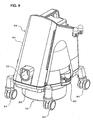
- the exhaust pump 54 is housed inside the cleaner body 56 as seen from Fig. 9.
- the cleaner body 56 has a structure in which a main unit 60 is mounted on a wheeled unit 58 vertically, and they are joined by a pair of left and right locking means 62 (only one is shown).
- the wheeled unit 58 has casters 64 at the four corners, and the water tank 10 is attached in the center thereof from below. The bottom surface of the water tank 10 is separated from the floor when attached to the wheeled unit 58, and the entirety is made movable by the casters 64.
- the exhaust pump 54 is provided inside the main unit 60 as described above; and, when the main unit 60 is mounted on from above on the wheeled unit 58 and the locking means 62 are fastened, a connecting element (not shown) provided in the center of the under surface of the main unit 60 is mated with the rib 50 that surrounds the dry filter 52 on the cover 16 of the water tank 10. In this condition, a suction tool is connected by a flexible connecting tube to the intake passage 32 that opens on the front side of the main unit 60.
- the above-described air flow would contain droplets that are mixed thereto, and dust that was not captured by the water, such as very fine dust or dust the surface thereof is not readily wetted by water, would be mixed in the air flow.
- Such water droplets and dust are heavier than air, they will be separated in the outer peripheral direction by the centrifugal force associated with the swirling motion of the air, adhere to the inner surface of the tank and thus be captured.
- the swirling air strikes the baffles 46 and 44, and thus water droplets and dust is captured thereby also. Air from which water droplets and dust thus have been removed enters from the exhaust port 40 into the exhaust space 30 while whirling and passes through the dry filter 52, so that it is sucked in by the exhaust pump 54 and exhausted into the atmosphere.
Landscapes
- Cyclones (AREA)
- Filters For Electric Vacuum Cleaners (AREA)
- Separation Of Particles Using Liquids (AREA)
Applications Claiming Priority (1)
| Application Number | Priority Date | Filing Date | Title |
|---|---|---|---|
| JP2005307984A JP2007111397A (ja) | 2005-10-24 | 2005-10-24 | 湿式電気掃除機 |
Publications (1)
| Publication Number | Publication Date |
|---|---|
| EP1777012A2 true EP1777012A2 (de) | 2007-04-25 |
Family
ID=37605828
Family Applications (1)
| Application Number | Title | Priority Date | Filing Date |
|---|---|---|---|
| EP06255482A Withdrawn EP1777012A2 (de) | 2005-10-24 | 2006-10-24 | Elektrische Nassreinigungsvorrichtung |
Country Status (4)
| Country | Link |
|---|---|
| US (1) | US20070089610A1 (de) |
| EP (1) | EP1777012A2 (de) |
| JP (1) | JP2007111397A (de) |
| CN (1) | CN1977747A (de) |
Cited By (3)
| Publication number | Priority date | Publication date | Assignee | Title |
|---|---|---|---|---|
| WO2009143728A1 (zh) * | 2008-05-27 | 2009-12-03 | Jianyi Yao | 一种消音滤烟器 |
| EP2471430A2 (de) * | 2009-08-26 | 2012-07-04 | Samsung Electronics Co., Ltd. | Staubsammler mit nasstrennung für einen staubsauger |
| EP2425757A4 (de) * | 2009-04-29 | 2018-02-28 | Samsung Electronics Co., Ltd. | Staubsammler mit nasstrennung für einen staubsauger |
Families Citing this family (18)
| Publication number | Priority date | Publication date | Assignee | Title |
|---|---|---|---|---|
| KR101015604B1 (ko) | 2008-08-26 | 2011-02-25 | 여승동 | 습식 진공청소기 |
| CN101669801B (zh) * | 2008-09-11 | 2012-05-30 | 胡海荣 | 旋风式水过滤集尘装置 |
| WO2010085050A2 (en) * | 2009-01-21 | 2010-07-29 | Samsung Gwangju Electronics Co., Ltd. | Dust separator and vacuum cleaner having the same |
| KR101566411B1 (ko) * | 2009-05-19 | 2015-11-06 | 삼성전자주식회사 | 진공청소기의 습식집진장치 |
| JP5610880B2 (ja) | 2010-07-01 | 2014-10-22 | キヤノン株式会社 | インクジェット装置 |
| KR20120095489A (ko) * | 2011-02-19 | 2012-08-29 | 윤장식 | 원심형식의 습식 청소기 |
| CN104507374B (zh) * | 2012-08-02 | 2017-03-29 | 达利通香港有限公司 | 真空吸尘器和湿式滤尘器 |
| CN103767628B (zh) * | 2012-10-19 | 2017-02-08 | 莱克电气股份有限公司 | 具有分离装置的干湿两用吸尘器 |
| CN102973208A (zh) * | 2012-12-04 | 2013-03-20 | 大连民族学院 | 旋转式三腔水过滤系统 |
| CN104323740B (zh) * | 2014-10-03 | 2016-09-07 | 张周新 | 一种干湿两用吸尘器 |
| CN107529928B (zh) * | 2015-04-13 | 2020-12-04 | 皇家飞利浦有限公司 | 无袋式真空清洁器 |
| CN105413318B (zh) * | 2015-12-15 | 2018-04-03 | 美的集团股份有限公司 | 用于除尘设备的过滤液箱及具有其的除尘设备 |
| CN105597460B (zh) | 2015-12-15 | 2017-08-29 | 美的集团股份有限公司 | 用于除尘设备的过滤液箱及具有其的除尘设备 |
| CN105498402A (zh) * | 2015-12-15 | 2016-04-20 | 美的集团股份有限公司 | 用于除尘设备的过滤液箱及具有其的除尘设备 |
| CN107999279B (zh) * | 2017-10-30 | 2024-05-03 | 江苏鑫复特环保科技有限公司 | 一种带连续液膜保护的湿式电除尘器用阳极室 |
| CN112386167A (zh) * | 2019-08-16 | 2021-02-23 | 博世电动工具(中国)有限公司 | 格栅过滤器,过滤系统以及吸尘器 |
| AU2020376860B2 (en) | 2019-10-31 | 2023-11-16 | Techtronic Cordless Gp | Separator configuration for a floor cleaner |
| JP7240366B2 (ja) * | 2020-09-10 | 2023-03-15 | シャープ株式会社 | 電気掃除機 |
Family Cites Families (2)
| Publication number | Priority date | Publication date | Assignee | Title |
|---|---|---|---|---|
| US4300924A (en) * | 1980-03-24 | 1981-11-17 | Paccar Inc. | Exhaust gas scrubber for internal combustion engines |
| US5192344A (en) * | 1991-09-10 | 1993-03-09 | Andre E. Thorn Bacon | Wet filter vacuum cleaner |
-
2005
- 2005-10-24 JP JP2005307984A patent/JP2007111397A/ja active Pending
-
2006
- 2006-10-23 US US11/584,836 patent/US20070089610A1/en not_active Abandoned
- 2006-10-24 CN CNA2006101507432A patent/CN1977747A/zh active Pending
- 2006-10-24 EP EP06255482A patent/EP1777012A2/de not_active Withdrawn
Cited By (5)
| Publication number | Priority date | Publication date | Assignee | Title |
|---|---|---|---|---|
| WO2009143728A1 (zh) * | 2008-05-27 | 2009-12-03 | Jianyi Yao | 一种消音滤烟器 |
| EP2425757A4 (de) * | 2009-04-29 | 2018-02-28 | Samsung Electronics Co., Ltd. | Staubsammler mit nasstrennung für einen staubsauger |
| EP2471430A2 (de) * | 2009-08-26 | 2012-07-04 | Samsung Electronics Co., Ltd. | Staubsammler mit nasstrennung für einen staubsauger |
| EP2471430A4 (de) * | 2009-08-26 | 2013-05-22 | Samsung Electronics Co Ltd | Staubsammler mit nasstrennung für einen staubsauger |
| US8728222B2 (en) | 2009-08-26 | 2014-05-20 | Samsung Electronics Co., Ltd. | Wet type dust collector for vacuum cleaner |
Also Published As
| Publication number | Publication date |
|---|---|
| JP2007111397A (ja) | 2007-05-10 |
| US20070089610A1 (en) | 2007-04-26 |
| CN1977747A (zh) | 2007-06-13 |
Similar Documents
| Publication | Publication Date | Title |
|---|---|---|
| EP1777012A2 (de) | Elektrische Nassreinigungsvorrichtung | |
| RU2328961C1 (ru) | Пылесос (варианты) | |
| US10813511B2 (en) | Electric vacuum cleaner | |
| JP3029292B2 (ja) | 真空清掃装置用のセパレータ | |
| US9226631B2 (en) | Cyclone separator and vacuum cleaner | |
| KR100964699B1 (ko) | 진공 청소기의 집진장치 | |
| JP2007275550A (ja) | 真空掃除機用の第2段分離装置 | |
| JP2006320713A (ja) | マルチサイクロン集塵装置 | |
| JP2005081134A (ja) | サイクロン分離装置及びこれを備えた掃除機 | |
| GB2439276A (en) | Dust collector of vacuum cleaner | |
| KR100546622B1 (ko) | 청소기의 집진장치 | |
| JP4621008B2 (ja) | 真空掃除機のゴミ分離装置 | |
| KR100556442B1 (ko) | 진공 청소기의 집진장치 | |
| KR20040050221A (ko) | 싸이클론 집진장치 | |
| JP2007021176A (ja) | ゴミ分離装置 | |
| KR20070021523A (ko) | 집진장치 | |
| CN115120134B (zh) | 旋风分离器及表面清洁装置 | |
| KR100546628B1 (ko) | 진공 청소기의 집진장치 | |
| KR100628044B1 (ko) | 진공청소기 | |
| KR100672474B1 (ko) | 진공청소기 | |
| KR100556443B1 (ko) | 진공 청소기의 집진장치 | |
| KR100577279B1 (ko) | 진공 청소기 | |
| KR100628082B1 (ko) | 진공청소기 | |
| KR100577277B1 (ko) | 진공청소기 | |
| KR100643695B1 (ko) | 사이클론 청소기 |
Legal Events
| Date | Code | Title | Description |
|---|---|---|---|
| PUAI | Public reference made under article 153(3) epc to a published international application that has entered the european phase |
Free format text: ORIGINAL CODE: 0009012 |
|
| AK | Designated contracting states |
Kind code of ref document: A2 Designated state(s): AT BE BG CH CY CZ DE DK EE ES FI FR GB GR HU IE IS IT LI LT LU LV MC NL PL PT RO SE SI SK TR |
|
| AX | Request for extension of the european patent |
Extension state: AL BA HR MK YU |
|
| STAA | Information on the status of an ep patent application or granted ep patent |
Free format text: STATUS: THE APPLICATION IS DEEMED TO BE WITHDRAWN |
|
| 18D | Application deemed to be withdrawn |
Effective date: 20090501 |