EP1775448A1 - Verfahren zur Steuerung einer Brennkraftmaschine mit Ventilhubumschaltung - Google Patents
Verfahren zur Steuerung einer Brennkraftmaschine mit Ventilhubumschaltung Download PDFInfo
- Publication number
- EP1775448A1 EP1775448A1 EP06121640A EP06121640A EP1775448A1 EP 1775448 A1 EP1775448 A1 EP 1775448A1 EP 06121640 A EP06121640 A EP 06121640A EP 06121640 A EP06121640 A EP 06121640A EP 1775448 A1 EP1775448 A1 EP 1775448A1
- Authority
- EP
- European Patent Office
- Prior art keywords
- correction
- intake manifold
- switching
- valve lift
- basic
- Prior art date
- Legal status (The legal status is an assumption and is not a legal conclusion. Google has not performed a legal analysis and makes no representation as to the accuracy of the status listed.)
- Granted
Links
Images
Classifications
-
- F—MECHANICAL ENGINEERING; LIGHTING; HEATING; WEAPONS; BLASTING
- F02—COMBUSTION ENGINES; HOT-GAS OR COMBUSTION-PRODUCT ENGINE PLANTS
- F02D—CONTROLLING COMBUSTION ENGINES
- F02D13/00—Controlling the engine output power by varying inlet or exhaust valve operating characteristics, e.g. timing
- F02D13/02—Controlling the engine output power by varying inlet or exhaust valve operating characteristics, e.g. timing during engine operation
- F02D13/0203—Variable control of intake and exhaust valves
- F02D13/0207—Variable control of intake and exhaust valves changing valve lift or valve lift and timing
-
- F—MECHANICAL ENGINEERING; LIGHTING; HEATING; WEAPONS; BLASTING
- F02—COMBUSTION ENGINES; HOT-GAS OR COMBUSTION-PRODUCT ENGINE PLANTS
- F02D—CONTROLLING COMBUSTION ENGINES
- F02D13/00—Controlling the engine output power by varying inlet or exhaust valve operating characteristics, e.g. timing
- F02D13/02—Controlling the engine output power by varying inlet or exhaust valve operating characteristics, e.g. timing during engine operation
-
- F—MECHANICAL ENGINEERING; LIGHTING; HEATING; WEAPONS; BLASTING
- F01—MACHINES OR ENGINES IN GENERAL; ENGINE PLANTS IN GENERAL; STEAM ENGINES
- F01L—CYCLICALLY OPERATING VALVES FOR MACHINES OR ENGINES
- F01L13/00—Modifications of valve-gear to facilitate reversing, braking, starting, changing compression ratio, or other specific operations
-
- F—MECHANICAL ENGINEERING; LIGHTING; HEATING; WEAPONS; BLASTING
- F02—COMBUSTION ENGINES; HOT-GAS OR COMBUSTION-PRODUCT ENGINE PLANTS
- F02D—CONTROLLING COMBUSTION ENGINES
- F02D41/00—Electrical control of supply of combustible mixture or its constituents
- F02D41/0002—Controlling intake air
-
- F—MECHANICAL ENGINEERING; LIGHTING; HEATING; WEAPONS; BLASTING
- F02—COMBUSTION ENGINES; HOT-GAS OR COMBUSTION-PRODUCT ENGINE PLANTS
- F02D—CONTROLLING COMBUSTION ENGINES
- F02D41/00—Electrical control of supply of combustible mixture or its constituents
- F02D41/02—Circuit arrangements for generating control signals
- F02D41/18—Circuit arrangements for generating control signals by measuring intake air flow
-
- F—MECHANICAL ENGINEERING; LIGHTING; HEATING; WEAPONS; BLASTING
- F02—COMBUSTION ENGINES; HOT-GAS OR COMBUSTION-PRODUCT ENGINE PLANTS
- F02D—CONTROLLING COMBUSTION ENGINES
- F02D41/00—Electrical control of supply of combustible mixture or its constituents
- F02D41/0002—Controlling intake air
- F02D2041/001—Controlling intake air for engines with variable valve actuation
-
- F—MECHANICAL ENGINEERING; LIGHTING; HEATING; WEAPONS; BLASTING
- F02—COMBUSTION ENGINES; HOT-GAS OR COMBUSTION-PRODUCT ENGINE PLANTS
- F02D—CONTROLLING COMBUSTION ENGINES
- F02D2200/00—Input parameters for engine control
- F02D2200/02—Input parameters for engine control the parameters being related to the engine
- F02D2200/04—Engine intake system parameters
- F02D2200/0402—Engine intake system parameters the parameter being determined by using a model of the engine intake or its components
-
- Y—GENERAL TAGGING OF NEW TECHNOLOGICAL DEVELOPMENTS; GENERAL TAGGING OF CROSS-SECTIONAL TECHNOLOGIES SPANNING OVER SEVERAL SECTIONS OF THE IPC; TECHNICAL SUBJECTS COVERED BY FORMER USPC CROSS-REFERENCE ART COLLECTIONS [XRACs] AND DIGESTS
- Y02—TECHNOLOGIES OR APPLICATIONS FOR MITIGATION OR ADAPTATION AGAINST CLIMATE CHANGE
- Y02T—CLIMATE CHANGE MITIGATION TECHNOLOGIES RELATED TO TRANSPORTATION
- Y02T10/00—Road transport of goods or passengers
- Y02T10/10—Internal combustion engine [ICE] based vehicles
- Y02T10/12—Improving ICE efficiencies
-
- Y—GENERAL TAGGING OF NEW TECHNOLOGICAL DEVELOPMENTS; GENERAL TAGGING OF CROSS-SECTIONAL TECHNOLOGIES SPANNING OVER SEVERAL SECTIONS OF THE IPC; TECHNICAL SUBJECTS COVERED BY FORMER USPC CROSS-REFERENCE ART COLLECTIONS [XRACs] AND DIGESTS
- Y02—TECHNOLOGIES OR APPLICATIONS FOR MITIGATION OR ADAPTATION AGAINST CLIMATE CHANGE
- Y02T—CLIMATE CHANGE MITIGATION TECHNOLOGIES RELATED TO TRANSPORTATION
- Y02T10/00—Road transport of goods or passengers
- Y02T10/10—Internal combustion engine [ICE] based vehicles
- Y02T10/40—Engine management systems
Definitions
- the present invention relates to a method for controlling an internal combustion engine with valve lift switching, in particular with discrete valve lift switching.
- valve lift switching in internal combustion engines is known in the art.
- systems such as the Vario Cam Plus from Porsche have been in mass production for several years (see also " Manual Combustion Engine”, published by: van Basshuysen / Shufer, Vierweg Verlag, 1st edition, April 2002 ).
- the problem with this technique is still the valve lift switching process as such.
- switching from small to large valve lift poses difficulties with respect to the torque neutrality of the internal combustion engine. Missing torque neutrality of the engine manifests itself in a noticeable jerking of the motor vehicle when switching from one to the other valve.
- the reason for the missing torque neutrality lies in hardly avoidable inaccuracies in the intake or intake model (intake manifold model) of the internal combustion engine.
- a separate model is stored in the engine control.
- the model data are in maps filed, which are formed by so-called support points.
- the quality criterion for the changeover is that the actual engine torque in both configurations - ie directly before and after the valve lift switchover - is as equal as possible.
- even small errors in the model calculation lead to torque differences and thus inaccuracies in the valve lift.
- Another problem at this point is that usually changes the combustion behavior of the internal combustion engine by the valve lift. This is mainly to be expected with duct injectors due to the changed flow cross-section at the valve. Another problem arises when in the course of valve lift switching also takes place a Brennvons grill, for example, a ottomotoric combustion in a controlled auto-ignition over.
- the models running in the engine control can be executed as accurately as desired.
- the problem with this is that the complexity of the models increases rapidly if all influencing parameters are to be recorded with a certain accuracy on a size to be imaged.
- Even modern engine control systems quickly reach their limits at this point. In this case, the memory and computational capacity of the engine control are quickly exhausted, so that ultimately compromises and compromises in accuracy must be made.
- the inventive method for controlling an internal combustion engine with valve lift switching comprises the following steps: determining a base cylinder filling, in particular a basic air quantity, using a basic intake manifold model for at least a first and a second valve lift of the internal combustion engine, starting from a detected intake manifold pressure, detecting a Shift-relevant pressure range for the valve lift switching on the basis of the detected intake manifold pressure and determining a switching cylinder filling corresponding to an operating point of the internal combustion engine for the switching-relevant pressure range using a Umschaltsaugrohrmodells, so that based on the Umschaltzylinder spallung controlled Ventilhubumscrien with approximately constant torque of the engine is feasible.
- the present method is preferably performed by an engine control of the internal combustion engine.
- the starting point of the method is the operating data of the internal combustion engine, which are constantly recorded by the engine control, such as the intake manifold pressure, the rotational speed, the throttle position and the like.
- One of the main elements of the present method is that outside the switching-relevant pressure range for the valve lift switching, the basic intake manifold model determines the basic cylinder charge corresponding to the operating point of the internal combustion engine.
- the basic intake manifold model according to an embodiment is carried out simultaneously for each possible valve lift of the internal combustion engine. This opens up the possibility that upon request of a valve lift switching by the engine control, the required operating data of the internal combustion engine for the new valve lift are already calculated by the basic intake manifold model.
- the cylinder charge is calculated with the aid of the change-over intake manifold model. This provides compared to the basic intake manifold model, a calculation of the cylinder charge with higher accuracy, so that taking into account a plurality of operating data of the internal combustion engine Ventilhubumscaria with approximately constant torque of the internal combustion engine is possible, while the storage and computational effort for the entire method of control the valve lift is limited.
- the switchover intake manifold model for the shift-related pressure range is composed of the basic intake manifold model for each valve lift and a charge correction model for each valve lift.
- the fill correction model for each valve lift provides more detailed cylinder fill data compared to the basic intake manifold model so that it is superimposed on the values of the basic intake manifold model.
- the basic intake manifold model operates with a basic map for each valve lift of the internal combustion engine.
- the filling correction model is also preferably based on characteristic diagrams stored in the engine control system, but they can also be carried out by appropriate non-map-based calculations, just like the basic intake manifold model.
- the basic intake manifold model and the charge correction model cooperate such that in the charge correction model, a correction value, in particular a correction air amount, for the basic cylinder charge for each valve lift that adds to the base cylinder charge results in a correction cylinder charge , While, according to an embodiment, the basic cylinder filling is also passed on to determine the operating data in parallel with the determined correction cylinder filling, it will now be based on the correction cylinder filling also calculates a correction of the operating data of the internal combustion engine.
- the specific correction quantities determined in this connection are, for example, an injection time correction, a spark angle correction and a correction of a throttle position. In this way, a filling correction map, which operates in the switching-relevant pressure range with higher accuracy in comparison to the basic intake manifold model, preferably enters the determination of the operating data of the internal combustion engine.
- a weighted determination of the correction cylinder filling takes place in that, as the distance from a switching pressure increases, the correction value enters the correction cylinder filling as the proportion decreases.
- the switching intake manifold model is formed limited to the shift-related pressure range by a detailed intake manifold model for each valve lift.
- the base intake manifold model alone is used to calculate the cylinder charge outside of the shift-relevant pressure range.
- the switching-relevant pressure range through the detail intake manifold model is used to determine the cylinder filling data. Since the detail intake manifold model is mapped to a narrower intake manifold pressure range compared to the basic intake manifold model, more capacity is available for storing operating data of the internal combustion engine with higher accuracy.
- the detail intake manifold model specifically calculates the shift cylinder charge for the respective valve lift, or it is determined based on a fill map specific to each valve lift.
- the detail intake manifold model is executed with greater accuracy than the basic intake manifold model with respect to the determination of the cylinder charge in order to save overall computing power and / or storage capacity.
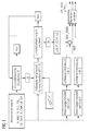
- FIG. Here is shown a flowchart of the method for valve lift switching, which is performed within the engine control of the internal combustion engine.
- the basis of this method is the recorded and forwarded to the engine control operating data of the internal combustion engine.
- These include, inter alia, the speed N, the pedal value PV, the intake manifold pressure MAP, the coolant temperature TCO, the oil temperature TOIL, the intake air temperature TIA, camshaft signals CAM_IN, CAM_EX and the cylinder-individual Automatzündwinkel IGA.
- the detected intake manifold pressure MAP preferably forms the starting point in order to control the switching of the valve lift which is dependent on the operating state of the internal combustion engine.
- the valve lift is exemplarily switched between the discrete valve lift 1 and the discrete valve lift 2. It is also conceivable that can be switched between more than two valve strokes, or that a continuous valve lift adjustment takes place.
- the intake manifold pressure MAP represents a measure of the amount of air supplied as a function of the operating state of the internal combustion engine. According to the amount of air that forms part of the cylinder charge, fuel is metered to achieve the torque required in accordance with the operating state of the internal combustion engine.
- the engine operating state or the above-mentioned operating data of the internal combustion engine are forwarded to the basic intake manifold model.
- the basic intake manifold model determines in each case in parallel for each controllable valve lift of the internal combustion engine and depending on the requested operating state or torque, the base cylinder filling.
- the base cylinder charge is preferably composed of a request for the basic air quantity MAF1, MAF2, which is then metered according to the amount of fuel for operation of the internal combustion engine.
- a switching-relevant pressure range is defined, in which a changeover takes place from one valve to another. If the internal combustion engine is located outside the changeover-relevant pressure range according to the measured intake manifold pressure MAP, the cylinder charge of the internal combustion engine is predetermined by the basic intake manifold model in the form of the basic cylinder charge.
- the base cylinder fill i.
- the basic air quantity can be calculated, for example, for each valve lift according to a calculation rule in the engine control. It is also conceivable to determine the basic air quantity for saving computing power and storage capacity based on a basic map.
- the basic pressure range ie the range in which the basic intake manifold model is used to calculate the cylinder charge
- the basic pressure range is relatively wide.
- To limit the computational effort is stored only a limited number of operating data in the base map and thus processable in the basic intake manifold model. This restriction is made in order not to increase the computational effort and complexity of such maps ineffective.
- the cylinder filling values in particular the basic air quantity MAF1, MAF2 for valve lift 1 and valve lift 2 are specified in normal operation, which are used for further engine control.
- the engine control system If the engine control system recognizes, based on the performance query, the intake manifold pressure MAP and / or a torque request, that the internal combustion engine is in the pressure range which is relevant for the changeover, the engine control system activates a changeover intake manifold model for determining the changeover cylinder charge. In the determination of the switching cylinder filling, the operating state of the internal combustion engine, the currently switched valve lift and the valve lift to be switched on. With the aid of this change-over intake manifold model, a more accurate determination of the cylinder charge, i. the shift cylinder charge during the shift from a first to a second valve lift, compared to the base cylinder charge, so that the valve lift of the engine with approximately constant torque, so torque neutrality is performed.
- the switching intake manifold model is composed of the basic intake manifold model for each valve lift and a charge correction model for each valve lift.
- the filling correction model determines, on the basis of calculations or by means of a filling correction map for the possible valve strokes of the internal combustion engine, correction values ⁇ MAF-CORR 1 and ⁇ MAF_CORR 2 for the cylinder charge. If the internal combustion engine is not in a pressure-relevant switching area, the filling correction model is not activated accordingly.
- the correction values .DELTA.MAF_CORR 1, 2 are superimposed on the air flow values MAF1, MAF2 from the basic intake manifold model. This superimposition takes place in an adder, in which the correction air quantity ⁇ MAF_CORR 1, ⁇ MAF_CORR 2, which can have positive and negative signs, are added to the basic air quantity MAF1, MAF2. Subsequently, both the basic air quantity MAF corresponding to the currently applied valve lift and the corrected basic air quantity MAF_CORR are forwarded to a torque correction block of the internal combustion engine.
- the above correction map sets of the fillet correction model which are represented for example by the diagram symbol in the fill correction model in FIG. 1, are designed for storage capacity reasons such that only a narrow suction tube pressure region is imaged.
- This pressure range corresponds to the shift-relevant pressure range, so that the correction of the charge correction characteristic map acts precisely in this pressure range.
- the pressure range is chosen so that the pressure value at which typically the valve lift switching takes place, is covered approximately in the middle.
- the Medkororrekturkennfelder are also exactly gedatet and cover advantageously all cylinder filling relevant factors such as engine speed, intake air temperature, camshaft position, swirl flap position, etc. from. This is achieved by the fact that the corresponding map points are explicitly approached and bedatet in the vehicle or engine application.
- a corresponding torque correction for the internal combustion engine is determined with the aid of a difference. It follows that the correction cylinder filling derived from the filling correction characteristic fields is based on the operating data of the internal combustion engine calculated on the basis of the basic intake manifold model is applied.
- the filling correction is weighted when approaching the switching-relevant pressure range. That the more one approaches the intake manifold switching pressure for the valve lift, the more the correction calculated by the charge correction model becomes more effective. This allows a particularly smooth transition between the valve lifts. Furthermore, it is advantageous if the finely tuned basic intake manifold model range is executed larger than the shift-relevant pressure range for the same amount of data, since then it is ensured in each case that the more accurate cylinder charge values are used for the switchover process.
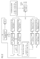
- the engine control system comprises the basic intake manifold model already discussed above and a detailed intake manifold model for the respectively possible valve strokes of the internal combustion engine. If no switching-relevant pressure range is detected by the engine control, the cylinder charge and thus the basic air quantity is specified by the basic intake manifold model in the same way as described above. If the engine control recognizes a switching-relevant pressure range on the basis of the operating state of the internal combustion engine, the detail intake manifold model is activated according to the method illustrated in FIG. 2, while the data of the basic intake manifold model are no longer forwarded to the torque model. The for the control of the internal combustion engine now to be specified amount of air is given solely by the detail intake manifold model.
- the torque model according to FIG. 2 is not based on the air flow values of the basic intake manifold model, the computation-intensive correction value calculations according to FIG. 1 are not required.
- the calculated amount of air of the detail intake manifold model goes directly into the torque model, so that subsequently the injection time TI, the ignition angle IGA and the throttle position TPS can be output.
- the main advantage of the method described above in the various embodiments is therefore that in the switching-relevant pressure range, the air mass flowing into the cylinder is calculated much more accurately. As a result, the torque prediction gains in accuracy and the switching of the valves is improved and runs smoothly.
- the fact that the maps are made narrow with respect to the pressure range saves space and conserves the resources of the engine control or the operating control unit.
- the calculation of the correction values takes place only in the changeover-relevant pressure range and the further calculation only for a given switchover requirement. Thus, the additional computational effort remains low. Likewise, the applicative effort is limited.
- Another advantage of the method is that it can be easily integrated into existing engine controls, regardless of the particular functional structure used.
Landscapes
- Engineering & Computer Science (AREA)
- Mechanical Engineering (AREA)
- General Engineering & Computer Science (AREA)
- Chemical & Material Sciences (AREA)
- Combustion & Propulsion (AREA)
- Output Control And Ontrol Of Special Type Engine (AREA)
- Combined Controls Of Internal Combustion Engines (AREA)
- Electrical Control Of Air Or Fuel Supplied To Internal-Combustion Engine (AREA)
- Valve Device For Special Equipments (AREA)
Abstract
Description
- Die vorliegende Erfindung betrifft ein Verfahren zur Steuerung einer Brennkraftmaschine mit Ventilhubumschaltung, insbesondere mit diskreter Ventilhubumschaltung.
- Das Prinzip der Ventilhubumschaltung bei Brennkraftmaschinen ist im Stand der Technik bekannt. So sind Systeme, wie z.B. das Vario Cam Plus der Fa. Porsche, seit einigen Jahren bereits in Serienfertigung (siehe auch "Handbuch Verbrennungsmotor", Herausgeber: van Basshuysen/Schäfer, Vierweg Verlag, 1. Auflage, April 2002). Problematisch bei dieser Technik ist nach wie vor der Ventilhubumschaltprozess als solcher. Insbesondere das Schalten von kleinem zu großem Ventilhub bereitet Schwierigkeiten in Bezug auf die Momentenneutralität der Brennkraftmaschine. Fehlende Momentenneutralität der Brennkraftmaschine äußert sich in einem spürbaren Ruckeln des Kraftfahrzeugs beim Umschalten von einem zum anderen Ventilhub. Der Grund für die fehlende Momentenneutralität liegt in kaum vermeidbaren Ungenauigkeiten im Schluck- oder Liefergradmodell (Saugrohrmodell) der Brennkraftmaschine.
- Diese Modelle, die in der Motorsteuerung laufen und dort mit den entsprechenden Betriebsdaten der Brennkraftmaschine versorgt werden, berechnen betriebspunktabhängig die dem Verbrennungsprozess zugeführte Luftmasse. Daraus wird unter Einhaltung eines bestimmten Luft-Kraftstoff-Verhältnisses unter Berücksichtigung des vorgegebenen Lambda-Werts die einzuspritzende Kraftstoffmenge berechnet. Diese Kraftstoffmenge bestimmt wiederum das zu erwartende Drehmoment des jeweiligen Arbeitsspiels der Brennkraftmaschine.
- Für jede Ventilhubkonfiguration ist in der Motorsteuerung ein eigenes Modell hinterlegt. Die Modelldaten sind in Kennfeldern abgelegt, die von so genannten Stützstellen gebildet werden. Das Gütekriterium für die Umschaltung besteht darin, dass das tatsächliche Motordrehmoment in beiden Konfigurationen - also direkt vor und nach der Ventilhubumschaltung - möglichst gleich ist. Bereits kleine Fehler in der Modellberechnung führen jedoch zu Momentenunterschieden und damit zu Ungenauigkeiten bei der Ventilhubumschaltung.
- Ein weiteres Problem an dieser Stelle besteht darin, dass sich durch die Ventilhubumschaltung in aller Regel das verbrennungstechnische Verhalten der Brennkraftmaschine ändert. Dies ist hauptsächlich bei Kanaleinspritzern aufgrund des veränderten Strömungsquerschnitts am Ventil zu erwarten. Ein weiteres Problem ergibt sich dann, wenn im Zuge der Ventilhubumschaltung auch noch ein Brennverfahrenswechsel stattfindet, beispielsweise geht eine ottomotorische Verbrennung in eine kontrollierte Selbstzündung über.
- Prinzipiell können die in der Motorsteuerung ablaufenden Modelle beliebig genau ausgeführt werden. Das Problem dabei besteht jedoch darin, dass die Komplexität der Modelle rasch zunimmt, wenn alle Einflussparameter auf eine abzubildende Größe mit einer bestimmten Genauigkeit erfasst werden sollen. Selbst moderne Motorsteuerungen stoßen an dieser Stelle schnell an ihre Grenzen. In diesem Fall sind die Speicher- und Rechenkapazität der Motorsteuerung schnell erschöpft, so dass letztendlich Kompromisse und Abstriche bezüglich der Genauigkeit gemacht werden müssen.
- Es ist daher die Aufgabe der vorliegenden Erfindung, ein Verfahren zur Steuerung einer Brennkraftmaschine mit Ventilhubumschaltung bereitzustellen, das sich durch eine verbesserte Momentenneutralität bei Ventilhubumschaltprozessen im Vergleich zum Stand der Technik auszeichnet.
- Das obige Problem wird durch ein Verfahren gemäß dem unabhängigen Patentanspruch 1 gelöst. Bevorzugte Ausführungsformen und Weiterentwicklungen der vorliegenden Erfindung gehen aus der folgenden Beschreibung, den begleitenden Zeichnungen und den anhängenden Ansprüchen hervor.
- Das erfindungsgemäße Verfahren zur Steuerung einer Brennkraftmaschine mit Ventilhubumschaltung umfasst die folgenden Schritte: Bestimmen einer Basis-Zylinderfüllung, insbesondere einer Basis-Luftmenge, mit Hilfe eines Basis-Saugrohrmodells für mindestens einen ersten und einen zweiten Ventilhub der Brennkraftmaschine ausgehend von einem erfassten Saugrohrdruck, Erkennen eines umschaltrelevanten Druckbereichs für die Ventilhubumschaltung anhand des erfassten Saugrohrdrucks und Bestimmen einer Umschalt-Zylinderfüllung entsprechend eines Betriebspunkts der Brennkraftmaschine für den umschaltrelevanten Druckbereich mit Hilfe eines Umschaltsaugrohrmodells, so dass die auf Grundlage der Umschaltzylinderfüllung angesteuerte Ventilhubumschaltung mit annähernd konstantem Drehmoment des Motors durchführbar ist.
- Das vorliegende Verfahren wird vorzugsweise durch eine Motorsteuerung der Brennkraftmaschine durchgeführt. Ausgangspunkt des Verfahrens bilden die ständig durch die Motorsteuerung erfassten Betriebsdaten der Brennkraftmaschine, wie beispielsweise der Saugrohrdruck, die Drehzahl, die Drosselklappenstellung und dergleichen. Eines der Hauptelemente des vorliegenden Verfahrens besteht darin, dass außerhalb des umschaltrelevanten Druckbereichs für die Ventilhubumschaltung das Basis-Saugrohrmodell die Basis-Zylinderfüllung entsprechend dem Betriebspunkt der Brennkraftmaschine bestimmt. Das Basis-Saugrohrmodell wird gemäß einer Ausführungsform gleichzeitig jeweils für jeden möglichen Ventilhub der Brennkraftmaschine durchgeführt. Dies eröffnet die Möglichkeit, dass bei Anforderung einer Ventilhubumschaltung durch die Motorsteuerung die erforderlichen Betriebsdaten der Brennkraftmaschine für den neuen Ventilhub bereits durch das Basis-Saugrohrmodell berechnet vorliegen.
- Sobald die Motorsteuerung erkennt, dass sich die Brennkraftmaschine in einem umschaltrelevanten Druckbereich zur Ventilhubumschaltung befindet, erfolgt die Berechnung der Zylinderfüllung mit Hilfe des Umschalt-Saugrohrmodells. Dies liefert im Vergleich zum Basis-Saugrohrmodell eine Berechnung der Zylinderfüllung mit höherer Genauigkeit, so dass unter Berücksichtigung einer Mehrzahl von Betriebsdaten der Brennkraftmaschine eine Ventilhubumschaltung mit annähernd konstantem Drehmoment der Brennkraftmaschine möglich ist, während gleichzeitig der Speicher- und Rechenaufwand für das gesamte Verfahren zur Steuerung der Ventilhubumschaltung begrenzt wird.
- Gemäß einer Ausführungsform setzt sich das Umschalt-Saugrohrmodell für den umschaltrelevanten Druckbereich aus dem Basis-Saugrohrmodell für jeden Ventilhub und einem Füllungskorrekturmodell für jeden Ventilhub zusammen. Das Füllungskorrekturmodell für jeden Ventilhub liefert detailliertere Zylinderfüllungsdaten im Vergleich zum Basis-Saugrohrmodell, so dass es korrigierend den Werten des Basis-Saugrohrmodells überlagert wird. Um die Zylinderfüllung mit geringem Aufwand bestimmen zu können, arbeitet das Basis-Saugrohrmodell mit jeweils einem Basis-Kennfeld für jeden Ventilhub der Brennkraftmaschine. Auch das Füllungskorrekturmodell basiert bevorzugt auf in der Motorsteuerung gespeicherten Kennfeldern, die aber auch genauso wie das Basis-Saugrohrmodell durch entsprechende nicht-kennfeldgestützte Berechnungen durchgeführt werden können.
- Im Umschalt-Saugrohrmodell arbeiten das Basis-Saugrohrmodell und das Füllungskorrekturmodell derart zusammen, dass in dem Füllungskorrekturmodell ein Korrekturwert, insbesondere eine Korrektur-Luftmenge, für die Basis-Zylinderfüllung für jeden Ventilhub bestimmt wird, der zur Basis-Zylinderfüllung addiert eine Korrektur-Zylinderfüllung ergibt. Während gemäß einer Ausführungsform parallel zur ermittelten Korrektur-Zylinderfüllung auch die Basis-Zylinderfüllung zur Bestimmung der Betriebsdaten weitergegeben wird, wird nun auf Grundlage der Korrektur-Zylinderfüllung auch eine Korrektur der Betriebsdaten der Brennkraftmaschine berechnet. Die in diesem Zusammenhang ermittelten spezifischen Korrekturgrößen sind beispielsweise eine Einspritzzeit-Korrektur, eine Zündwinkel-Korrektur und eine Korrektur einer Drosselklappenstellung. Auf diese Weise geht bevorzugt ein Füllungskorrekturkennfeld, das im umschaltrelevanten Druckbereich mit höherer Genauigkeit im Vergleich zum Basis-Saugrohrmodell arbeitet, in die Bestimmung der Betriebsdaten der Brennkraftmaschine ein.
- Gemäß einer weiteren Ausführungsform erfolgt ein gewichtetes Bestimmen der Korrektur-Zylinderfüllung, indem mit zunehmender Entfernung von einem Umschaltdruck der Korrekturwert mit abnehmendem Anteil in die Korrektur-Zylinderfüllung eingeht.
- Gemäß einer weiteren Ausführungsform der vorliegenden Erfindung wird das Umschalt-Saugrohrmodell allein durch ein Detail-Saugrohrmodell für jeden Ventilhub begrenzt auf den umschaltrelevanten Druckbereich gebildet.
- In dieser Ausführungsform wird außerhalb des umschaltrelevanten Druckbereichs allein das Basis-Saugrohrmodell zur Berechnung der Zylinderfüllung genutzt. Um innerhalb des umschaltrelevanten Druckbereichs eine höhere Genauigkeit zur Bestimmung der Betriebsdaten der Brennkraftmaschine zu gewährleisten, wird der umschaltrelevante Druckbereich durch das Detail-Saugrohrmodell zur Bestimmung der Zylinderfüllungsdaten herangezogen. Da im Vergleich zum Basis-Saugrohrmodell das Detail-Saugrohrmodell auf einen schmaleren Saugrohr-Druckbereich abgebildet ist, steht hier mehr Kapazität zur Speicherung von Betriebsdaten der Brennkraftmaschine mit höherer Genauigkeit zur Verfügung.
- Gemäß einer weiteren Ausführungsform berechnet das Detail-Saugrohrmodell die Umschalt-Zylinderfüllung für den jeweiligen Ventilhub spezifisch oder diese wird basierend auf einem für jeden Ventilhub spezifischen Füllungskennfeld bestimmt.
- Gemäß einer weiteren Ausführungsform wird das Detail-Saugrohrmodell mit größerer Genauigkeit als das Basis-Saugrohrmodell in Bezug auf die Bestimmung der Zylinderfüllung ausgeführt, um insgesamt Rechenleistung und/oder Speicherkapazität zu sparen.
- Die vorliegende Erfindung wird unter Bezugnahme auf die begleitende Zeichnung näher erläutert. Es zeigen:
- Fig. 1
- ein Ablaufdiagramm der Ventilhubumschaltung von Hub 1 nach Hub 2 gemäß einer ersten Ausführungsform und
- Fig. 2
- ein Ablaufdiagramm der Ventilhubschaltung von Hub 1 nach Hub 2 gemäß einer zweiten Ausführungsform.
- Eine Ausführungsform der vorliegenden Erfindung ist in Fig. 1 dargestellt. Hier ist ein Ablaufdiagramm des Verfahrens zur Ventilhubumschaltung gezeigt, das innerhalb der Motorsteuerung der Brennkraftmaschine ausgeführt wird. Grundlage für dieses Verfahren bilden die erfassten und an die Motorsteuerung weitergeleiteten Betriebsdaten der Brennkraftmaschine. Diese umfassen unter anderem die Drehzahl N, den Pedalwert PV, den Saugrohrdruck MAP, die Kühlmitteltemperatur TCO, die Öltemperatur TOIL, die Ansauglufttemperatur TIA, Nockenwellensignale CAM_IN, CAM_EX und den zylinderindividuellen Gesamtzündwinkel IGA.
- Der erfasste Saugrohrdruck MAP bildet bevorzugt den Ausgangspunkt, um die vom Betriebszustand der Brennkraftmaschine abhängige Umschaltung des Ventilhubs anzusteuern. Der Ventilhub wird beispielgebend zwischen dem diskreten Ventilhub 1 und dem diskreten Ventilhub 2 umgeschaltet. Es ist des Weiteren denkbar, dass zwischen mehr als zwei Ventilhüben umgeschaltet werden kann, oder dass eine kontinuierliche Ventilhubverstellung erfolgt.
- Der Saugrohrdruck MAP stellt ein Maß für die in Abhängigkeit vom Betriebszustand der Brennkraftmaschine zugeführte Luftmenge dar. Entsprechend der Luftmenge, die einen Bestandteil der Zylinderfüllung bildet, wird Kraftstoff zugemessen, um das entsprechend dem Betriebszustand der Brennkraftmaschine geforderte Drehmoment zu erzielen.
- Der Motorbetriebszustand bzw. die oben genannten Betriebsdaten der Brennkraftmaschine werden an das Basis-Saugrohrmodell weitergeleitet. Das Basis-Saugrohrmodell bestimmt jeweils parallel für jeden ansteuerbaren Ventilhub der Brennkraftmaschine und in Abhängigkeit vom angeforderten Betriebszustand oder Drehmoment die Basis-Zylinderfüllung. Die Basis-Zylinderfüllung setzt sich bevorzugt aus einer Anforderung für die Basis-Luftmenge MAF1, MAF2 zusammen, der entsprechend dann die Kraftstoffmenge zum Betrieb der Brennkraftmaschine zugemessen wird.
- In Abhängigkeit vom Absolutwert des Saugrohrdrucks MAP und dem Betriebszustand der Brennkraftmaschine wird ein umschaltrelevanter Druckbereich definiert, in dem eine Umschaltung von einem zu einem anderen Ventilhub erfolgt. Befindet sich die Brennkraftmaschine gemäß dem gemessenen Saugrohrdruck MAP au-ßerhalb des umschaltrelevanten Druckbereichs, wird die Zylinderfüllung der Brennkraftmaschine durch das Basis-Saugrohrmodell in Form der Basis-Zylinderfüllung vorgegeben. Die Basis-Zylinderfüllung, d.h. vorzugsweise die Basis-Luftmenge, kann beispielsweise für jeden Ventilhub gemäß einer Berechnungsvorschrift in der Motorsteuerung berechnet werden. Es ist ebenfalls denkbar, die Basis-Luftmenge zur Einsparung von Rechenleistung und Speicherkapazität basierend auf einem Basis-Kennfeld zu ermitteln.
- Verglichen mit dem umschaltrelevanten Druckbereich ist der Basis-Druckbereich, d.h. der Bereich, in dem das Basis-Saugrohrmodell zur Berechnung der Zylinderfüllung herangezogen wird, relativ breit. Um den Rechenaufwand zu begrenzen, ist nur eine begrenzte Anzahl Betriebsdaten im Basis-Kennfeld gespeichert und somit im Basis-Saugrohrmodell verarbeitbar. Diese Einschränkung wird vorgenommen, um den Rechenaufwand und die Komplexität derartiger Kennfelder nicht ins Unwirtschaftliche zu steigern. Basierend auf diesem Basis-Kennfeld, das für jeden Ventilhub der Brennkraftmaschine vorliegt, werden im Normalbetrieb die Zylinderfüllungswerte, im Speziellen die Basis-Luftmenge MAF1, MAF2 für Ventilhub 1 und Ventilhub 2, vorgegeben, die zur weiteren Motorsteuerung genutzt werden.
- Erkennt die Motorsteuerung anhand der Leistungsabfrage, des Saugrohrdrucks MAP und/oder einer Momentenabfrage, dass sich die Brennkraftmaschine im umschaltrelevanten Druckbereich befindet, aktiviert die Motorsteuerung ein Umschalt-Saugrohrmodell zur Bestimmung der Umschalt-Zylinderfüllung. In die Bestimmung der Umschalt-Zylinderfüllung gehen der Betriebszustand der Brennkraftmaschine, der momentan geschaltete Ventilhub und der zu schaltende Ventilhub ein. Mit Hilfe dieses Umschalt-Saugrohrmodells erfolgt eine genauere Bestimmung der Zylinderfüllung, d.h. der Umschalt-Zylinderfüllung während des Umschaltens von einem ersten auf einen zweiten Ventilhub, im Vergleich zur Basis-Zylinderfüllung, so dass die Ventilhubumschaltung der Brennkraftmaschine mit annähernd konstantem Drehmoment, also Momentenneutralität, durchgeführt wird.
- Gemäß einer Ausführungsform setzt sich das Umschalt-Saugrohrmodell aus dem Basis-Saugrohrmodell für jeden Ventilhub und einem Füllungskorrekturmodell für jeden Ventilhub zusammen. Nach dem Erkennen eines umschaltrelevanten Druckbereichs bestimmt das Füllungskorrekturmodell anhand von Berechnungen oder mittels eines Füllungskorrekturkennfelds für die möglichen Ventilhübe der Brennkraftmaschine Korrekturwerte ΔMAF-CORR 1 und ΔMAF_CORR 2 für die Zylinderfüllung. Sollte sich die Brennkraftmaschine nicht in einem umschaltrelevanten Druckbereich befinden, wird entsprechend das Füllungskorrekturmodell nicht aktiviert. Erfolgt nach der Bestimmung der oben genannten Korrekturwerte eine Umschaltanforderung für den Ventilhub durch die Motorsteuerung, werden die Korrekturwerte ΔMAF_CORR 1, 2 den Luftmengen-Werten MAF1, MAF2 aus dem Basis-Saugrohrmodell überlagert. Diese Überlagerung erfolgt in einem Addierer, in dem die Korrektur-Luftmenge ΔMAF_CORR 1, ΔMAF_CORR 2, die positives und negatives Vorzeichen haben können, zur Basis-Luftmenge MAF1, MAF2 addiert werden. Nachfolgend werden sowohl die Basis-Luftmenge MAF entsprechend dem gerade anliegenden Ventilhub und die korrigierte Basis-Luftmenge MAF_CORR an einen Momentenkorrektur-Block der Brennkraftmaschine weitergeleitet.
- Die oben genannten Korrekturkennfeldsätze des Füllungskorrekturmodells, die beispielsweise durch das Diagrammsymbol beim Füllungskorrekturmodell in Fig. 1 dargestellt sind, sind aus Speicherkapazitätsgründen derart ausgeführt, dass lediglich ein schmaler Saugrohr-Druckbereich abgebildet wird. Dieser Druckbereich entspricht dem umschaltrelevanten Druckbereich, so dass die Korrektur des Füllungskorrekturkennfelds gerade in diesem Druckbereich wirkt. Der Druckbereich wird dabei so gewählt, dass der Druckwert, bei dem typischerweise die Ventilhubumschaltung erfolgt, etwa mittig abgedeckt ist. Die Füllungskorrekturkennfelder sind darüber hinaus exakt bedatet und decken vorteilhafter Weise alle zylinderfüllungsrelevanten Einflussgrößen, wie Motordrehzahl, Ansauglufttemperatur, Nockenwellenstellung, Drallklappenstellung, etc. ab. Dies wird dadurch erreicht, dass die entsprechenden Kennfeldpunkte bei der Fahrzeug- bzw. Motorapplikation explizit angefahren und bedatet werden.
- Im weiteren Verfahren wird aus der Korrektur-Zylinderfüllung MAF_CORR, vorzugsweise der korrigierten Luftmenge, im Vergleich zur Basis-Zylinderfüllung Basis-MAF, vorzugsweise der Basis-Luftmenge, eine entsprechende Momentenkorrektur für die Brennkraftmaschine mit Hilfe einer Differenz ermittelt. Daraus folgt, dass die aus den Füllungskorrekturkennfeldern abgeleitete Korrektur-Zylinderfüllung auf die anhand des Basis-Saugrohrmodells berechneten Betriebsdaten der Brennkraftmaschine angewandt wird. In dem bereits oben genannten Block "Momentenkorrektur" der Brennkraftmaschine werden daher spezifische Korrekturgrößen für die Betriebsdaten der Brennkraftmaschine berechnet, wie beispielsweise eine Korrektur der Einspritzzeit ΔTI, eine Korrektur des Zündwinkels, ΔIGA, eine Korrektur der Drosselklappenstellung ΔTPS und dergleichen. Die Weiterverrechnung der Korrekturwerte erfordert daher einen gewissen Rechenaufwand, weil diese zum Konstanthalten des Drehmoments der Brennkraftmaschine in allen Betriebsgrößen berücksichtigt werden muss.
- Gemäß einer weiteren Ausgestaltung des Verfahrens wird bei Annäherung an den umschaltrelevanten Druckbereich die Füllungskorrektur gewichtet berücksichtigt. D.h. je mehr man sich dem Saugrohr-Umschaltdruck für den Ventilhub nähert, desto stärker greift die durch das Füllungskorrekturmodell berechnete Korrektur. Dies ermöglicht einen besonders weichen Übergang zwischen den Ventilhüben. Des Weiteren ist es vorteilhaft, wenn der fein abgestimmte Basis-Saugrohrmodellbereich bei gleicher Datenmenge größer als der umschaltrelevante Druckbereich ausgeführt wird, da dann in jedem Fall sichergestellt ist, dass für den Umschaltprozess die genaueren Zylinderfüllungswerte verwendet werden.
- Gemäß einer weiteren in Fig. 2 dargestellten Ausführungsform umfasst die Motorsteuerung das bereits oben diskutierte Basis-Saugrohrmodell und ein Detail-Saugrohrmodell für die jeweils möglichen Ventilhübe der Brennkraftmaschine. Sofern kein umschaltrelevanter Druckbereich durch die Motorsteuerung erkannt wird, wird die Zylinderfüllung und somit die Basis-Luftmenge durch das Basis-Saugrohrmodell in gleicher Weise wie oben beschrieben vorgegeben. Erkennt die Motorsteuerung anhand des Betriebszustands der Brennkraftmaschine einen umschaltrelevanten Druckbereich, wird gemäß dem in Fig. 2 dargestellten Verfahren das Detail-Saugrohrmodell aktiviert, während die Daten des Basis-Saugrohrmodells nicht länger an das Momentenmodell weitergeleitet werden. Die für die Steuerung der Brennkraftmaschine nun vorzugebende Luftmenge wird allein durch das Detail-Saugrohrmodell vorgegeben.
- Während die bereits oben genannten Betriebszustandsdaten der Brennkraftmaschine sowohl in das Detail-Saugrohrmodell wie auch in das Basis-Saugrohrmodell einfließen, erfolgt im umschaltrelevanten Druckbereich keine Korrektur des Basis-Saugrohrmodells. Stattdessen wird eine eigenständige Bestimmung der Zylinderfüllung, vorzugsweise der Luftmenge DETAIL MAF1 und DETAIL MAF2, in diesem Bereich durchgeführt. Diese Bestimmung kann entweder durch Berechnung oder gestützt auf Kennfelder erfolgen. Die bestimmte Zylinderfüllung, insbesondere der berechnete MAF-Wert, geht dann in das Drehmomentenmodell der Brennkraftmaschine ein. Dies hat den Vorteil, dass die ursprüngliche Struktur des Verfahrens bzw. der Steuerung der Brennkraftmaschine nur an einer Stelle aufgebrochen werden muss, während sie ansonsten beibehalten werden kann.
- Ähnlich wie das Füllungskorrekturmodell ist das Detail-Saugrohrmodell nur auf den umschaltrelevanten Druckbereich abgebildet. Daraus folgt aufgrund einer ähnlich großen gespeicherten Datenmenge die Möglichkeit einer höheren Genauigkeit im Vergleich zum Basis-Saugrohrmodell, das auf einen weitaus größeren Druckbereich abgebildet ist.
- Da das Momentenmodell gemäß Fig. 2 nicht auf den Luftmengen-Werten des Basis-Saugrohrmodells aufbaut, sind die rechenintensiven Korrekturwertberechnungen gemäß Fig. 1 nicht erforderlich. Die berechnete Luftmenge des Detail-Saugrohrmodells geht direkt in das Momentenmodell ein, so dass nachfolgend die Einspritzzeit TI, der Zündwinkel IGA und die Drosselklappenstellung TPS ausgegeben werden kann.
- Von Vorteil ist es darüber hinaus, wenn der Wechsel vom Basis-Saugrohrmodell zum Detail-Saugrohrmodell hysteresebehaftet gestaltet wird. Auf diese Weise wird ein ständiges Umschalten bei geringen Betriebspunktvariationen verhindert, das ebenfalls als Jitter bekannt ist.
- Der Hauptvorteil des oben in den verschiedenen Ausführungsformen dargestellten Verfahrens besteht somit darin, dass im umschaltrelevanten Druckbereich die in den Zylinder strömende Luftmasse deutlich exakter berechnet wird. Dadurch gewinnt die Drehmomentenprädiktion an Genauigkeit und der Umschaltvorgang der Ventile wird verbessert und läuft ruckfrei ab. Die Tatsache, dass die Kennfelder bezüglich des Druckbereichs schmal ausgeführt werden, spart Speicherplatz und schont die Ressourcen der Motorsteuerung bzw. des Betriebssteuergeräts. Des Weiteren erfolgen die Berechnung der Korrekturwerte nur im umschaltrelevanten Druckbereich und die Weiterverrechnung nur bei gegebener Umschaltanforderung. Somit bleibt der zusätzliche Rechenaufwand gering. Ebenso hält sich der applikative Aufwand in Grenzen. Ein weiterer Vorteil des Verfahrens besteht darin, dass es einfach in bestehende Motorsteuerungen integriert werden kann, unabhängig von der jeweils verwendeten Funktionsstruktur.
Claims (11)
- Verfahren zur Steuerung einer Brennkraftmaschine mit Ventilhubumschaltung, das die folgenden Schritte aufweist:a. Bestimmen einer Basis-Zylinderfüllung, insbesondere einer Basis-Luftmenge (MAF 1, MAF 2), mit Hilfe eines Basis-Saugrohrmodells für mindestens einen ersten und einen zweiten Ventilhub der Brennkraftmaschine ausgehend von einem erfassten Saugrohrdruck (MAP),b. Erkennen eines umschaltrelevanten Druckbereichs für die Ventilhubumschaltung anhand des erfassten Saugrohrdrucks (MAP) undc. Bestimmen einer Umschalt-Zylinderfüllung entsprechend eines Betriebspunkts der Brennkraftmaschine für den umschaltrelevanten Druckbereich mit Hilfe eines Umschalt-Saugrohrmodells, so dass die auf Grundlage der Umschalt-Zylinderfüllung angesteuerte Ventilhubumschaltung mit annähernd konstantem Drehmoment der Brennkraftmaschine durchführbar ist.
- Verfahren gemäß Anspruch 1, in dem sich das Umschalt-Saugrohrmodell aus dem Basis-Saugrohrmodell für jeden Ventilhub und einem Füllungskorrekturmodell für jeden Ventilhub zusammensetzt.
- Verfahren gemäß Anspruch 1 oder 2, in dem das Basis-Saugrohrmodell die Basis-Zylinderfüllung für jeden Ventilhub jeweils basierend auf einem eigenen Basis-Kennfeld bestimmt.
- Verfahren gemäß Anspruch 2 oder 3, in dem das Füllungskorrekturmodell einen Korrekturwert (ΔMAF_CORR 1, ΔMAF_CORR 2), insbesondere eine Korrektur-Luftmenge, für die Basis-Zylinderfüllung (MAF 1, MAF 2) für jeden Ventilhub bestimmt, der zur Basis-Zylinderfüllung (MAF 1, MAF 2) addiert eine Korrektur-Zylinderfüllung (MAF_KORR) ergibt.
- Verfahren gemäß Anspruch 2 oder 4, in dem das Korrekturmodell jeweils ein Füllungskorrekturkennfeld je Ventilhub aufweist.
- Verfahren gemäß Anspruch 5, mit dem weiteren Schritt:Abdecken nur des umschaltrelevanten Druckbereichs mit dem Füllungskorrekturkennfeld.
- Verfahren gemäß einem der Ansprüche 4 bis 6, mit dem weiteren Schritt:Korrigieren von Betriebsdaten des Motors zu dessen Momentenkorrektur unter Berücksichtigung der Korrektur-Zylinderfüllung (MAF_KORR) und auf dieser Grundlage bestimmter spezifischer Korrekturgrößen, vorzugsweise einer Einspritzzeit-Korrektur (ΔTI), einer Zündwinkel-Korrektur (ΔIGA) und einer Korrektur einer Drosselklappenstellung.
- Verfahren gemäß Anspruch 7, mit dem weiteren Schritt:gewichtetes Bestimmen der Korrektur-Zylinderfüllung, indem mit zunehmender Entfernung von einem Umschaltdruck der Korrekturwert (ΔMAF_CORR 1, ΔMAF_CORR 2) mit abnehmendem Anteil in die Korrektur-Zylinderfüllung eingeht.
- Verfahren gemäß Anspruch 1, in dem das Umschalt-Saugrohrmodell allein durch ein Detail-Saugrohrmodell für jeden Ventilhub begrenzt auf den umschaltrelevanten Druckbereich gebildet wird.
- Verfahren gemäß Anspruch 9, in dem das Detail-Saugrohrmodell die Umschalt-Zylinderfüllung für den jeweiligen Ventilhub spezifisch berechnet oder basierend auf einem für jeden Ventilhub spezifischen Füllungskennfeld bestimmt.
- Verfahren gemäß Anspruch 9, in dem das Detail-Saugrohrmodell mit größerer Genauigkeit als das Basis-Saugrohrmodell in Bezug auf die Bestimmung der Zylinderfüllung ausgeführt ist, um Rechenleistung und/oder Speicherkapazität zu sparen.
Applications Claiming Priority (1)
| Application Number | Priority Date | Filing Date | Title |
|---|---|---|---|
| DE102005048703A DE102005048703B3 (de) | 2005-10-11 | 2005-10-11 | Verfahren zur Steuerung einer Brennkraftmaschine mit Ventilhubumschaltung |
Publications (3)
| Publication Number | Publication Date |
|---|---|
| EP1775448A1 true EP1775448A1 (de) | 2007-04-18 |
| EP1775448B1 EP1775448B1 (de) | 2008-02-27 |
| EP1775448B8 EP1775448B8 (de) | 2008-05-07 |
Family
ID=37441835
Family Applications (1)
| Application Number | Title | Priority Date | Filing Date |
|---|---|---|---|
| EP06121640A Active EP1775448B8 (de) | 2005-10-11 | 2006-10-02 | Verfahren zur Steuerung einer Brennkraftmaschine mit Ventilhubumschaltung |
Country Status (6)
| Country | Link |
|---|---|
| US (1) | US7386387B2 (de) |
| EP (1) | EP1775448B8 (de) |
| KR (1) | KR101262178B1 (de) |
| AT (1) | ATE387576T1 (de) |
| DE (2) | DE102005048703B3 (de) |
| ES (1) | ES2303313T3 (de) |
Cited By (2)
| Publication number | Priority date | Publication date | Assignee | Title |
|---|---|---|---|---|
| WO2009087008A1 (de) * | 2008-01-10 | 2009-07-16 | Continental Automotive Gmbh | Verfahren und vorrichtung zur steuerung einer brennkraftmaschine |
| WO2016188768A1 (de) * | 2015-05-22 | 2016-12-01 | Continental Automotive Gmbh | Verfahren zum steuern eines umschaltvorgangs eines ventils und steuergerät |
Families Citing this family (6)
| Publication number | Priority date | Publication date | Assignee | Title |
|---|---|---|---|---|
| KR100833865B1 (ko) | 2007-04-25 | 2008-06-02 | 엘지전자 주식회사 | 스팀건조기 및 그 제어방법 |
| DE102007024823B4 (de) * | 2007-05-29 | 2014-10-23 | Continental Automotive Gmbh | Verfahren und Vorrichtung zur Bestimmung eines Ansteuerparameters für einen Kraftstoffinjektor einer Brennkraftmaschine |
| DE102008003832B4 (de) * | 2008-01-10 | 2010-04-08 | Continental Automotive Gmbh | Verfahren und Vorrichtung zur Steuerung einer Brennkraftmaschine mit variablem Ventilhub sowie damit ausgestattetes Kraftfahrzeug |
| DE102008001081B4 (de) * | 2008-04-09 | 2021-11-04 | Robert Bosch Gmbh | Verfahren und Motorsteuergerät zum Steuern eines Verbrennungsmotors |
| KR101209742B1 (ko) * | 2010-11-04 | 2012-12-07 | 기아자동차주식회사 | 연속 가변 밸브 리프트(cvvl)기구 탑재 엔진간 밸브리프트 편차 보상방법 |
| GB2563393B (en) * | 2017-06-12 | 2020-08-05 | Jaguar Land Rover Ltd | Controlling an air charge provided to an engine |
Citations (4)
| Publication number | Priority date | Publication date | Assignee | Title |
|---|---|---|---|---|
| WO1999009303A1 (de) * | 1997-08-14 | 1999-02-25 | Siemens Aktiengesellschaft | Verfahren zur einstellung des ventilhubes |
| GB2333377A (en) * | 1998-01-16 | 1999-07-21 | Denso Corp | Determining cylinder-charged air quantity in an engine with variable valve control |
| EP1152128A2 (de) * | 2000-04-29 | 2001-11-07 | Bayerische Motoren Werke Aktiengesellschaft | Verfahren und Vorrichtung zur elektronischen Steuerung von Aktuatoren einer Brennkraftmaschine mit variabler Gaswechselsteuerung |
| JP2005171862A (ja) * | 2003-12-10 | 2005-06-30 | Denso Corp | 内燃機関の制御装置 |
Family Cites Families (5)
| Publication number | Priority date | Publication date | Assignee | Title |
|---|---|---|---|---|
| EP0399829B1 (de) * | 1989-05-25 | 1994-07-27 | Honda Giken Kogyo Kabushiki Kaisha | Verfahren zur Fehlererkennung bei einem Ventilzeitsteuerungssystem für eine innere Verbrennungskraftmaschine |
| US5000280A (en) * | 1990-04-04 | 1991-03-19 | Honda Giken Kogyo Kabushiki Kaisha | Driving wheel slip control system for vehicles |
| JP2673325B2 (ja) * | 1991-11-13 | 1997-11-05 | 本田技研工業株式会社 | 内燃エンジンの制御装置 |
| JPH1073068A (ja) * | 1996-08-29 | 1998-03-17 | Honda Motor Co Ltd | 内燃機関の点火時期制御装置 |
| DE102004011236A1 (de) * | 2004-03-04 | 2005-09-29 | Bayerische Motoren Werke Ag | Prozesssteuersystem |
-
2005
- 2005-10-11 DE DE102005048703A patent/DE102005048703B3/de not_active Expired - Fee Related
-
2006
- 2006-10-02 AT AT06121640T patent/ATE387576T1/de not_active IP Right Cessation
- 2006-10-02 DE DE502006000392T patent/DE502006000392D1/de active Active
- 2006-10-02 ES ES06121640T patent/ES2303313T3/es active Active
- 2006-10-02 EP EP06121640A patent/EP1775448B8/de active Active
- 2006-10-11 US US11/546,498 patent/US7386387B2/en active Active
- 2006-10-11 KR KR1020060098770A patent/KR101262178B1/ko active Active
Patent Citations (4)
| Publication number | Priority date | Publication date | Assignee | Title |
|---|---|---|---|---|
| WO1999009303A1 (de) * | 1997-08-14 | 1999-02-25 | Siemens Aktiengesellschaft | Verfahren zur einstellung des ventilhubes |
| GB2333377A (en) * | 1998-01-16 | 1999-07-21 | Denso Corp | Determining cylinder-charged air quantity in an engine with variable valve control |
| EP1152128A2 (de) * | 2000-04-29 | 2001-11-07 | Bayerische Motoren Werke Aktiengesellschaft | Verfahren und Vorrichtung zur elektronischen Steuerung von Aktuatoren einer Brennkraftmaschine mit variabler Gaswechselsteuerung |
| JP2005171862A (ja) * | 2003-12-10 | 2005-06-30 | Denso Corp | 内燃機関の制御装置 |
Cited By (3)
| Publication number | Priority date | Publication date | Assignee | Title |
|---|---|---|---|---|
| WO2009087008A1 (de) * | 2008-01-10 | 2009-07-16 | Continental Automotive Gmbh | Verfahren und vorrichtung zur steuerung einer brennkraftmaschine |
| US8364383B2 (en) | 2008-01-10 | 2013-01-29 | Continental Automotive Gmbh | Method and apparatus for controlling an internal combustion engine |
| WO2016188768A1 (de) * | 2015-05-22 | 2016-12-01 | Continental Automotive Gmbh | Verfahren zum steuern eines umschaltvorgangs eines ventils und steuergerät |
Also Published As
| Publication number | Publication date |
|---|---|
| ES2303313T3 (es) | 2008-08-01 |
| US7386387B2 (en) | 2008-06-10 |
| EP1775448B8 (de) | 2008-05-07 |
| DE502006000392D1 (de) | 2008-04-10 |
| KR101262178B1 (ko) | 2013-05-14 |
| US20070088486A1 (en) | 2007-04-19 |
| EP1775448B1 (de) | 2008-02-27 |
| DE102005048703B3 (de) | 2007-04-05 |
| ATE387576T1 (de) | 2008-03-15 |
| KR20070040318A (ko) | 2007-04-16 |
Similar Documents
| Publication | Publication Date | Title |
|---|---|---|
| DE10006127C2 (de) | Verfahren und System zur Ermittlung der Luftladung im Zylinder für zukünftige Motorereignisse | |
| DE3408223C2 (de) | ||
| DE3408215C2 (de) | ||
| DE69324727T2 (de) | Zündungssteuersystem und Methode für eine Brennkraftmaschine | |
| DE69424756T2 (de) | Verfahren und System zur Bestimmung der Zylinderluftladung einer Brennkraftmaschine | |
| DE69409621T2 (de) | Regeleinrichtung für Brennkraftmaschinen | |
| DE69831838T2 (de) | Brennstoffeinspritzsteuerungssystem für Brennkraftmaschine | |
| DE102007012604B4 (de) | Verfahren zum Regeln einer Einspritzung eines Injektors einer direkteinspritzenden Verbrennungskraftmaschine und direkteinspritzende Verbrennungskraftmaschine | |
| DE102004004573A1 (de) | Gerät zur Steuerung des Motordrehstopps unter Abschätzung kinetischer Energie und der Stopposition | |
| DE10219382A1 (de) | Steuerungsvorrichtung für eine Brennkraftmaschine | |
| DE10322514A1 (de) | Luftstromabschätzung für Motoren mit bedarfsabhängigem Hubraum | |
| DE102013211260A1 (de) | Abschätzungsvorrichtung für die Zylindereinlassluftmenge in einem Verbrennungsmotor | |
| DE69313486T2 (de) | Verfahren und System zur Steuerung von Brennstoffmaschine | |
| DE10046597B4 (de) | Steuersystem für Motoren mit Direkteinspritzung | |
| DE19720009C2 (de) | Verfahren zur Zylindergleichstellung bezüglich der Kraftstoff-Einspritzmenge bei einer Brennkraftmaschine | |
| DE4315885C1 (de) | Verfahren zur Drehmomenteinstellung | |
| DE60304067T2 (de) | Kraftstoffeinspritzsystem | |
| EP1775448B1 (de) | Verfahren zur Steuerung einer Brennkraftmaschine mit Ventilhubumschaltung | |
| DE68903639T2 (de) | Verfahren und vorrichtung zur steuerung von verbrennungsmotoren. | |
| DE10238060A1 (de) | Verfahren und System zum Betrieb eines Innenbrennkraftmotors mit Funkenzündung und Direkteinspritzung, der Betriebsarten mit variablem Kompressionsverhältnis hat | |
| DE102017105853A1 (de) | Verfahren zum Bestimmen einer Luftmenge in einem Brennraum eines Verbrennungsmotors, Verbrennungsmotor und Fahrzeug | |
| DE102008000547A1 (de) | Drehmomentensteuersystem | |
| WO2009143858A1 (de) | Verfahren zur regelung eines einspritzvorgangs einer verbrennungskraftmaschine, steuergerät für eine verbrennungskraftmaschine und eine verbrennungskraftmaschine | |
| DE19752220A1 (de) | System zum Steuern von Dieselmotoremissionen | |
| DE102014211714B4 (de) | Steuerung des Motorzündzeitpunkts während AGR-Modusübergängen |
Legal Events
| Date | Code | Title | Description |
|---|---|---|---|
| PUAI | Public reference made under article 153(3) epc to a published international application that has entered the european phase |
Free format text: ORIGINAL CODE: 0009012 |
|
| 17P | Request for examination filed |
Effective date: 20061214 |
|
| AK | Designated contracting states |
Kind code of ref document: A1 Designated state(s): AT BE BG CH CY CZ DE DK EE ES FI FR GB GR HU IE IS IT LI LT LU LV MC NL PL PT RO SE SI SK TR |
|
| AX | Request for extension of the european patent |
Extension state: AL BA HR MK YU |
|
| GRAP | Despatch of communication of intention to grant a patent |
Free format text: ORIGINAL CODE: EPIDOSNIGR1 |
|
| GRAS | Grant fee paid |
Free format text: ORIGINAL CODE: EPIDOSNIGR3 |
|
| RAP1 | Party data changed (applicant data changed or rights of an application transferred) |
Owner name: SIEMENS VDO AUTOMOTIVE AG |
|
| AKX | Designation fees paid |
Designated state(s): AT BE BG CH CY CZ DE DK EE ES FI FR GB GR HU IE IS IT LI LT LU LV MC NL PL PT RO SE SI SK TR |
|
| GRAA | (expected) grant |
Free format text: ORIGINAL CODE: 0009210 |
|
| AK | Designated contracting states |
Kind code of ref document: B1 Designated state(s): AT BE BG CH CY CZ DE DK EE ES FI FR GB GR HU IE IS IT LI LT LU LV MC NL PL PT RO SE SI SK TR |
|
| REG | Reference to a national code |
Ref country code: GB Ref legal event code: FG4D Free format text: NOT ENGLISH |
|
| RAP2 | Party data changed (patent owner data changed or rights of a patent transferred) |
Owner name: VDO AUTOMOTIVE AG |
|
| REG | Reference to a national code |
Ref country code: CH Ref legal event code: EP |
|
| REG | Reference to a national code |
Ref country code: IE Ref legal event code: FG4D Free format text: LANGUAGE OF EP DOCUMENT: GERMAN |
|
| REF | Corresponds to: |
Ref document number: 502006000392 Country of ref document: DE Date of ref document: 20080410 Kind code of ref document: P |
|
| NLT2 | Nl: modifications (of names), taken from the european patent patent bulletin |
Owner name: VDO AUTOMOTIVE AG Effective date: 20080319 |
|
| REG | Reference to a national code |
Ref country code: SE Ref legal event code: TRGR |
|
| REG | Reference to a national code |
Ref country code: CH Ref legal event code: NV Representative=s name: SIEMENS SCHWEIZ AG |
|
| RAP2 | Party data changed (patent owner data changed or rights of a patent transferred) |
Owner name: CONTINENTAL AUTOMOTIVE GMBH |
|
| PG25 | Lapsed in a contracting state [announced via postgrant information from national office to epo] |
Ref country code: FI Free format text: LAPSE BECAUSE OF FAILURE TO SUBMIT A TRANSLATION OF THE DESCRIPTION OR TO PAY THE FEE WITHIN THE PRESCRIBED TIME-LIMIT Effective date: 20080227 |
|
| REG | Reference to a national code |
Ref country code: ES Ref legal event code: FG2A Ref document number: 2303313 Country of ref document: ES Kind code of ref document: T3 |
|
| NLT2 | Nl: modifications (of names), taken from the european patent patent bulletin |
Owner name: CONTINENTAL AUTOMOTIVE GMBH Effective date: 20080716 |
|
| PG25 | Lapsed in a contracting state [announced via postgrant information from national office to epo] |
Ref country code: SI Free format text: LAPSE BECAUSE OF FAILURE TO SUBMIT A TRANSLATION OF THE DESCRIPTION OR TO PAY THE FEE WITHIN THE PRESCRIBED TIME-LIMIT Effective date: 20080227 Ref country code: PL Free format text: LAPSE BECAUSE OF FAILURE TO SUBMIT A TRANSLATION OF THE DESCRIPTION OR TO PAY THE FEE WITHIN THE PRESCRIBED TIME-LIMIT Effective date: 20080227 Ref country code: LV Free format text: LAPSE BECAUSE OF FAILURE TO SUBMIT A TRANSLATION OF THE DESCRIPTION OR TO PAY THE FEE WITHIN THE PRESCRIBED TIME-LIMIT Effective date: 20080227 |
|
| REG | Reference to a national code |
Ref country code: IE Ref legal event code: FD4D |
|
| PG25 | Lapsed in a contracting state [announced via postgrant information from national office to epo] |
Ref country code: DK Free format text: LAPSE BECAUSE OF FAILURE TO SUBMIT A TRANSLATION OF THE DESCRIPTION OR TO PAY THE FEE WITHIN THE PRESCRIBED TIME-LIMIT Effective date: 20080227 Ref country code: PT Free format text: LAPSE BECAUSE OF FAILURE TO SUBMIT A TRANSLATION OF THE DESCRIPTION OR TO PAY THE FEE WITHIN THE PRESCRIBED TIME-LIMIT Effective date: 20080721 Ref country code: IE Free format text: LAPSE BECAUSE OF FAILURE TO SUBMIT A TRANSLATION OF THE DESCRIPTION OR TO PAY THE FEE WITHIN THE PRESCRIBED TIME-LIMIT Effective date: 20080227 Ref country code: CZ Free format text: LAPSE BECAUSE OF FAILURE TO SUBMIT A TRANSLATION OF THE DESCRIPTION OR TO PAY THE FEE WITHIN THE PRESCRIBED TIME-LIMIT Effective date: 20080227 |
|
| ET | Fr: translation filed | ||
| PG25 | Lapsed in a contracting state [announced via postgrant information from national office to epo] |
Ref country code: RO Free format text: LAPSE BECAUSE OF FAILURE TO SUBMIT A TRANSLATION OF THE DESCRIPTION OR TO PAY THE FEE WITHIN THE PRESCRIBED TIME-LIMIT Effective date: 20080227 |
|
| PLBE | No opposition filed within time limit |
Free format text: ORIGINAL CODE: 0009261 |
|
| STAA | Information on the status of an ep patent application or granted ep patent |
Free format text: STATUS: NO OPPOSITION FILED WITHIN TIME LIMIT |
|
| PG25 | Lapsed in a contracting state [announced via postgrant information from national office to epo] |
Ref country code: LT Free format text: LAPSE BECAUSE OF FAILURE TO SUBMIT A TRANSLATION OF THE DESCRIPTION OR TO PAY THE FEE WITHIN THE PRESCRIBED TIME-LIMIT Effective date: 20080227 |
|
| PGFP | Annual fee paid to national office [announced via postgrant information from national office to epo] |
Ref country code: LU Payment date: 20081016 Year of fee payment: 3 |
|
| 26N | No opposition filed |
Effective date: 20081128 |
|
| PGFP | Annual fee paid to national office [announced via postgrant information from national office to epo] |
Ref country code: AT Payment date: 20081015 Year of fee payment: 3 Ref country code: ES Payment date: 20081027 Year of fee payment: 3 Ref country code: SK Payment date: 20080930 Year of fee payment: 3 |
|
| PGFP | Annual fee paid to national office [announced via postgrant information from national office to epo] |
Ref country code: SE Payment date: 20081014 Year of fee payment: 3 Ref country code: BE Payment date: 20081120 Year of fee payment: 3 |
|
| REG | Reference to a national code |
Ref country code: CH Ref legal event code: PCAR Free format text: SIEMENS SCHWEIZ AG;INTELLECTUAL PROPERTY FREILAGERSTRASSE 40;8047 ZUERICH (CH) |
|
| PG25 | Lapsed in a contracting state [announced via postgrant information from national office to epo] |
Ref country code: EE Free format text: LAPSE BECAUSE OF FAILURE TO SUBMIT A TRANSLATION OF THE DESCRIPTION OR TO PAY THE FEE WITHIN THE PRESCRIBED TIME-LIMIT Effective date: 20080227 Ref country code: BG Free format text: LAPSE BECAUSE OF FAILURE TO SUBMIT A TRANSLATION OF THE DESCRIPTION OR TO PAY THE FEE WITHIN THE PRESCRIBED TIME-LIMIT Effective date: 20080527 |
|
| PGFP | Annual fee paid to national office [announced via postgrant information from national office to epo] |
Ref country code: FR Payment date: 20081014 Year of fee payment: 3 |
|
| PG25 | Lapsed in a contracting state [announced via postgrant information from national office to epo] |
Ref country code: MC Free format text: LAPSE BECAUSE OF NON-PAYMENT OF DUE FEES Effective date: 20081031 |
|
| PG25 | Lapsed in a contracting state [announced via postgrant information from national office to epo] |
Ref country code: CY Free format text: LAPSE BECAUSE OF FAILURE TO SUBMIT A TRANSLATION OF THE DESCRIPTION OR TO PAY THE FEE WITHIN THE PRESCRIBED TIME-LIMIT Effective date: 20080227 |
|
| BERE | Be: lapsed |
Owner name: VDO AUTOMOTIVE A.G. Effective date: 20091031 |
|
| REG | Reference to a national code |
Ref country code: NL Ref legal event code: V1 Effective date: 20100501 |
|
| EUG | Se: european patent has lapsed | ||
| PG25 | Lapsed in a contracting state [announced via postgrant information from national office to epo] |
Ref country code: IS Free format text: LAPSE BECAUSE OF NON-PAYMENT OF DUE FEES Effective date: 20081031 |
|
| REG | Reference to a national code |
Ref country code: SK Ref legal event code: MM4A Ref document number: E 4436 Country of ref document: SK Effective date: 20091002 |
|
| REG | Reference to a national code |
Ref country code: FR Ref legal event code: ST Effective date: 20100630 |
|
| PG25 | Lapsed in a contracting state [announced via postgrant information from national office to epo] |
Ref country code: NL Free format text: LAPSE BECAUSE OF NON-PAYMENT OF DUE FEES Effective date: 20100501 Ref country code: HU Free format text: LAPSE BECAUSE OF FAILURE TO SUBMIT A TRANSLATION OF THE DESCRIPTION OR TO PAY THE FEE WITHIN THE PRESCRIBED TIME-LIMIT Effective date: 20080828 Ref country code: FR Free format text: LAPSE BECAUSE OF NON-PAYMENT OF DUE FEES Effective date: 20091102 |
|
| PG25 | Lapsed in a contracting state [announced via postgrant information from national office to epo] |
Ref country code: TR Free format text: LAPSE BECAUSE OF FAILURE TO SUBMIT A TRANSLATION OF THE DESCRIPTION OR TO PAY THE FEE WITHIN THE PRESCRIBED TIME-LIMIT Effective date: 20080227 Ref country code: AT Free format text: LAPSE BECAUSE OF NON-PAYMENT OF DUE FEES Effective date: 20091002 Ref country code: SK Free format text: LAPSE BECAUSE OF NON-PAYMENT OF DUE FEES Effective date: 20091002 |
|
| PG25 | Lapsed in a contracting state [announced via postgrant information from national office to epo] |
Ref country code: BE Free format text: LAPSE BECAUSE OF NON-PAYMENT OF DUE FEES Effective date: 20091031 Ref country code: GR Free format text: LAPSE BECAUSE OF FAILURE TO SUBMIT A TRANSLATION OF THE DESCRIPTION OR TO PAY THE FEE WITHIN THE PRESCRIBED TIME-LIMIT Effective date: 20080528 |
|
| REG | Reference to a national code |
Ref country code: ES Ref legal event code: FD2A Effective date: 20110302 |
|
| PG25 | Lapsed in a contracting state [announced via postgrant information from national office to epo] |
Ref country code: LU Free format text: LAPSE BECAUSE OF NON-PAYMENT OF DUE FEES Effective date: 20091002 |
|
| PG25 | Lapsed in a contracting state [announced via postgrant information from national office to epo] |
Ref country code: SE Free format text: LAPSE BECAUSE OF NON-PAYMENT OF DUE FEES Effective date: 20091003 |
|
| REG | Reference to a national code |
Ref country code: CH Ref legal event code: PL |
|
| GBPC | Gb: european patent ceased through non-payment of renewal fee |
Effective date: 20101002 |
|
| PG25 | Lapsed in a contracting state [announced via postgrant information from national office to epo] |
Ref country code: ES Free format text: LAPSE BECAUSE OF NON-PAYMENT OF DUE FEES Effective date: 20110301 Ref country code: CH Free format text: LAPSE BECAUSE OF NON-PAYMENT OF DUE FEES Effective date: 20101031 Ref country code: LI Free format text: LAPSE BECAUSE OF NON-PAYMENT OF DUE FEES Effective date: 20101031 |
|
| PG25 | Lapsed in a contracting state [announced via postgrant information from national office to epo] |
Ref country code: GB Free format text: LAPSE BECAUSE OF NON-PAYMENT OF DUE FEES Effective date: 20101002 |
|
| PG25 | Lapsed in a contracting state [announced via postgrant information from national office to epo] |
Ref country code: ES Free format text: LAPSE BECAUSE OF NON-PAYMENT OF DUE FEES Effective date: 20091003 |
|
| PGFP | Annual fee paid to national office [announced via postgrant information from national office to epo] |
Ref country code: IT Payment date: 20091031 Year of fee payment: 4 |
|
| PGFP | Annual fee paid to national office [announced via postgrant information from national office to epo] |
Ref country code: DE Payment date: 20181031 Year of fee payment: 13 |
|
| REG | Reference to a national code |
Ref country code: DE Ref legal event code: R119 Ref document number: 502006000392 Country of ref document: DE |
|
| PG25 | Lapsed in a contracting state [announced via postgrant information from national office to epo] |
Ref country code: DE Free format text: LAPSE BECAUSE OF NON-PAYMENT OF DUE FEES Effective date: 20200501 |