EP1775267A2 - Einrichtung und Verfahren zur Wiederverwertung von Kehrgut, Abfällen aus Wasserreinigungsgeräten und dergleichen - Google Patents
Einrichtung und Verfahren zur Wiederverwertung von Kehrgut, Abfällen aus Wasserreinigungsgeräten und dergleichen Download PDFInfo
- Publication number
- EP1775267A2 EP1775267A2 EP06425045A EP06425045A EP1775267A2 EP 1775267 A2 EP1775267 A2 EP 1775267A2 EP 06425045 A EP06425045 A EP 06425045A EP 06425045 A EP06425045 A EP 06425045A EP 1775267 A2 EP1775267 A2 EP 1775267A2
- Authority
- EP
- European Patent Office
- Prior art keywords
- water
- pump
- wash
- tank
- sludge
- Prior art date
- Legal status (The legal status is an assumption and is not a legal conclusion. Google has not performed a legal analysis and makes no representation as to the accuracy of the status listed.)
- Granted
Links
- XLYOFNOQVPJJNP-UHFFFAOYSA-N water Substances O XLYOFNOQVPJJNP-UHFFFAOYSA-N 0.000 title claims abstract description 91
- 239000002699 waste material Substances 0.000 title claims abstract description 32
- 238000000034 method Methods 0.000 title claims abstract description 19
- 230000008569 process Effects 0.000 title claims abstract description 18
- 238000004064 recycling Methods 0.000 title claims abstract description 14
- 238000010408 sweeping Methods 0.000 title claims abstract description 8
- 239000000463 material Substances 0.000 claims abstract description 61
- 239000002351 wastewater Substances 0.000 claims abstract description 59
- 239000000126 substance Substances 0.000 claims abstract description 56
- 239000010802 sludge Substances 0.000 claims abstract description 43
- 238000003860 storage Methods 0.000 claims abstract description 41
- 238000012216 screening Methods 0.000 claims abstract description 39
- 238000000926 separation method Methods 0.000 claims abstract description 31
- 238000011282 treatment Methods 0.000 claims abstract description 26
- 229910052751 metal Inorganic materials 0.000 claims abstract description 25
- 239000002184 metal Substances 0.000 claims abstract description 25
- 239000003153 chemical reaction reagent Substances 0.000 claims abstract description 16
- 238000005406 washing Methods 0.000 claims abstract description 16
- 238000005345 coagulation Methods 0.000 claims abstract description 14
- 230000015271 coagulation Effects 0.000 claims abstract description 14
- 238000001556 precipitation Methods 0.000 claims abstract description 13
- 230000018044 dehydration Effects 0.000 claims abstract description 12
- 238000006297 dehydration reaction Methods 0.000 claims abstract description 12
- 150000002739 metals Chemical class 0.000 claims abstract description 12
- 238000009412 basement excavation Methods 0.000 claims abstract description 4
- 239000004576 sand Substances 0.000 claims description 42
- 238000006243 chemical reaction Methods 0.000 claims description 15
- 239000011146 organic particle Substances 0.000 claims description 15
- 238000011068 loading method Methods 0.000 claims description 13
- 229920000867 polyelectrolyte Polymers 0.000 claims description 13
- HEMHJVSKTPXQMS-UHFFFAOYSA-M Sodium hydroxide Chemical compound [OH-].[Na+] HEMHJVSKTPXQMS-UHFFFAOYSA-M 0.000 claims description 12
- 239000000701 coagulant Substances 0.000 claims description 12
- 239000006148 magnetic separator Substances 0.000 claims description 12
- -1 ferrous metals Chemical class 0.000 claims description 11
- JVBXVOWTABLYPX-UHFFFAOYSA-L sodium dithionite Chemical compound [Na+].[Na+].[O-]S(=O)S([O-])=O JVBXVOWTABLYPX-UHFFFAOYSA-L 0.000 claims description 10
- 239000002245 particle Substances 0.000 claims description 9
- 239000005708 Sodium hypochlorite Substances 0.000 claims description 8
- 239000008187 granular material Substances 0.000 claims description 8
- SUKJFIGYRHOWBL-UHFFFAOYSA-N sodium hypochlorite Chemical compound [Na+].Cl[O-] SUKJFIGYRHOWBL-UHFFFAOYSA-N 0.000 claims description 8
- CWYNVVGOOAEACU-UHFFFAOYSA-N Fe2+ Chemical compound [Fe+2] CWYNVVGOOAEACU-UHFFFAOYSA-N 0.000 claims description 7
- 230000033228 biological regulation Effects 0.000 claims description 7
- 239000002002 slurry Substances 0.000 claims description 7
- 229910021578 Iron(III) chloride Inorganic materials 0.000 claims description 6
- 239000003344 environmental pollutant Substances 0.000 claims description 6
- 230000003311 flocculating effect Effects 0.000 claims description 6
- RBTARNINKXHZNM-UHFFFAOYSA-K iron trichloride Chemical compound Cl[Fe](Cl)Cl RBTARNINKXHZNM-UHFFFAOYSA-K 0.000 claims description 6
- 239000000203 mixture Substances 0.000 claims description 6
- 231100000719 pollutant Toxicity 0.000 claims description 6
- 238000004062 sedimentation Methods 0.000 claims description 6
- 239000003795 chemical substances by application Substances 0.000 claims description 5
- 238000000605 extraction Methods 0.000 claims description 5
- 230000001376 precipitating effect Effects 0.000 claims description 5
- 238000002360 preparation method Methods 0.000 claims description 5
- 239000006228 supernatant Substances 0.000 claims description 5
- AXCZMVOFGPJBDE-UHFFFAOYSA-L calcium dihydroxide Chemical compound [OH-].[OH-].[Ca+2] AXCZMVOFGPJBDE-UHFFFAOYSA-L 0.000 claims description 4
- 239000000920 calcium hydroxide Substances 0.000 claims description 4
- 229910001861 calcium hydroxide Inorganic materials 0.000 claims description 4
- 238000011010 flushing procedure Methods 0.000 claims description 4
- 239000006260 foam Substances 0.000 claims description 4
- 238000005201 scrubbing Methods 0.000 claims description 4
- FGUUSXIOTUKUDN-IBGZPJMESA-N C1(=CC=CC=C1)N1C2=C(NC([C@H](C1)NC=1OC(=NN=1)C1=CC=CC=C1)=O)C=CC=C2 Chemical compound C1(=CC=CC=C1)N1C2=C(NC([C@H](C1)NC=1OC(=NN=1)C1=CC=CC=C1)=O)C=CC=C2 FGUUSXIOTUKUDN-IBGZPJMESA-N 0.000 claims description 2
- 239000002352 surface water Substances 0.000 claims description 2
- 239000000284 extract Substances 0.000 claims 3
- 238000011084 recovery Methods 0.000 abstract description 14
- 239000011368 organic material Substances 0.000 abstract description 12
- 238000009264 composting Methods 0.000 abstract description 6
- 239000002994 raw material Substances 0.000 abstract description 6
- 239000004568 cement Substances 0.000 abstract description 5
- 230000007613 environmental effect Effects 0.000 abstract description 4
- 239000000243 solution Substances 0.000 description 17
- 101100069128 Saccharomyces cerevisiae (strain ATCC 204508 / S288c) GPA2 gene Proteins 0.000 description 9
- 239000008213 purified water Substances 0.000 description 7
- 230000008901 benefit Effects 0.000 description 6
- 230000005484 gravity Effects 0.000 description 6
- 238000005299 abrasion Methods 0.000 description 5
- 238000010586 diagram Methods 0.000 description 4
- XLYOFNOQVPJJNP-UHFFFAOYSA-M hydroxide Chemical compound [OH-] XLYOFNOQVPJJNP-UHFFFAOYSA-M 0.000 description 4
- 229910000831 Steel Inorganic materials 0.000 description 3
- 238000004140 cleaning Methods 0.000 description 3
- 230000004048 modification Effects 0.000 description 3
- 238000012986 modification Methods 0.000 description 3
- 229920002635 polyurethane Polymers 0.000 description 3
- 239000004814 polyurethane Substances 0.000 description 3
- 238000006722 reduction reaction Methods 0.000 description 3
- 229910001220 stainless steel Inorganic materials 0.000 description 3
- 239000010935 stainless steel Substances 0.000 description 3
- 239000010959 steel Substances 0.000 description 3
- OYPRJOBELJOOCE-UHFFFAOYSA-N Calcium Chemical compound [Ca] OYPRJOBELJOOCE-UHFFFAOYSA-N 0.000 description 2
- VYZAMTAEIAYCRO-UHFFFAOYSA-N Chromium Chemical compound [Cr] VYZAMTAEIAYCRO-UHFFFAOYSA-N 0.000 description 2
- DGAQECJNVWCQMB-PUAWFVPOSA-M Ilexoside XXIX Chemical compound C[C@@H]1CC[C@@]2(CC[C@@]3(C(=CC[C@H]4[C@]3(CC[C@@H]5[C@@]4(CC[C@@H](C5(C)C)OS(=O)(=O)[O-])C)C)[C@@H]2[C@]1(C)O)C)C(=O)O[C@H]6[C@@H]([C@H]([C@@H]([C@H](O6)CO)O)O)O.[Na+] DGAQECJNVWCQMB-PUAWFVPOSA-M 0.000 description 2
- 230000009471 action Effects 0.000 description 2
- 230000015572 biosynthetic process Effects 0.000 description 2
- 239000011575 calcium Substances 0.000 description 2
- 229910052791 calcium Inorganic materials 0.000 description 2
- 238000000151 deposition Methods 0.000 description 2
- 238000010790 dilution Methods 0.000 description 2
- 239000012895 dilution Substances 0.000 description 2
- 238000004090 dissolution Methods 0.000 description 2
- 239000003792 electrolyte Substances 0.000 description 2
- 150000002118 epoxides Chemical class 0.000 description 2
- 229910010272 inorganic material Inorganic materials 0.000 description 2
- 239000011147 inorganic material Substances 0.000 description 2
- 238000002156 mixing Methods 0.000 description 2
- 239000004033 plastic Substances 0.000 description 2
- 229920003023 plastic Polymers 0.000 description 2
- 239000000843 powder Substances 0.000 description 2
- 239000002244 precipitate Substances 0.000 description 2
- 230000001603 reducing effect Effects 0.000 description 2
- 230000009467 reduction Effects 0.000 description 2
- 239000011734 sodium Substances 0.000 description 2
- 229910052708 sodium Inorganic materials 0.000 description 2
- 230000032258 transport Effects 0.000 description 2
- 229910001369 Brass Inorganic materials 0.000 description 1
- OKTJSMMVPCPJKN-UHFFFAOYSA-N Carbon Chemical compound [C] OKTJSMMVPCPJKN-UHFFFAOYSA-N 0.000 description 1
- ZAMOUSCENKQFHK-UHFFFAOYSA-N Chlorine atom Chemical compound [Cl] ZAMOUSCENKQFHK-UHFFFAOYSA-N 0.000 description 1
- RYGMFSIKBFXOCR-UHFFFAOYSA-N Copper Chemical compound [Cu] RYGMFSIKBFXOCR-UHFFFAOYSA-N 0.000 description 1
- 238000007792 addition Methods 0.000 description 1
- 239000004411 aluminium Substances 0.000 description 1
- 229910052782 aluminium Inorganic materials 0.000 description 1
- XAGFODPZIPBFFR-UHFFFAOYSA-N aluminium Chemical compound [Al] XAGFODPZIPBFFR-UHFFFAOYSA-N 0.000 description 1
- 239000002518 antifoaming agent Substances 0.000 description 1
- 239000010951 brass Substances 0.000 description 1
- 239000011449 brick Substances 0.000 description 1
- 229910052799 carbon Inorganic materials 0.000 description 1
- 238000005119 centrifugation Methods 0.000 description 1
- 239000000460 chlorine Substances 0.000 description 1
- 229910052801 chlorine Inorganic materials 0.000 description 1
- 238000005352 clarification Methods 0.000 description 1
- 230000001112 coagulating effect Effects 0.000 description 1
- 239000004567 concrete Substances 0.000 description 1
- 229910052802 copper Inorganic materials 0.000 description 1
- 239000010949 copper Substances 0.000 description 1
- 238000005202 decontamination Methods 0.000 description 1
- 230000003588 decontaminative effect Effects 0.000 description 1
- 238000004332 deodorization Methods 0.000 description 1
- 230000001419 dependent effect Effects 0.000 description 1
- 238000009826 distribution Methods 0.000 description 1
- WBZKQQHYRPRKNJ-UHFFFAOYSA-L disulfite Chemical compound [O-]S(=O)S([O-])(=O)=O WBZKQQHYRPRKNJ-UHFFFAOYSA-L 0.000 description 1
- GRWZHXKQBITJKP-UHFFFAOYSA-N dithionous acid Chemical compound OS(=O)S(O)=O GRWZHXKQBITJKP-UHFFFAOYSA-N 0.000 description 1
- 238000001035 drying Methods 0.000 description 1
- 230000008030 elimination Effects 0.000 description 1
- 238000003379 elimination reaction Methods 0.000 description 1
- 238000011049 filling Methods 0.000 description 1
- 229910001385 heavy metal Inorganic materials 0.000 description 1
- 229930195733 hydrocarbon Natural products 0.000 description 1
- 150000002430 hydrocarbons Chemical class 0.000 description 1
- 150000004679 hydroxides Chemical class 0.000 description 1
- 231100001240 inorganic pollutant Toxicity 0.000 description 1
- 230000010354 integration Effects 0.000 description 1
- 238000009533 lab test Methods 0.000 description 1
- 230000035800 maturation Effects 0.000 description 1
- 231100000219 mutagenic Toxicity 0.000 description 1
- 230000003505 mutagenic effect Effects 0.000 description 1
- 239000003921 oil Substances 0.000 description 1
- 230000010355 oscillation Effects 0.000 description 1
- 230000001590 oxidative effect Effects 0.000 description 1
- 238000010979 pH adjustment Methods 0.000 description 1
- 230000020477 pH reduction Effects 0.000 description 1
- 239000003973 paint Substances 0.000 description 1
- 230000002265 prevention Effects 0.000 description 1
- 238000012545 processing Methods 0.000 description 1
- 238000000746 purification Methods 0.000 description 1
- 239000000523 sample Substances 0.000 description 1
- HRZFUMHJMZEROT-UHFFFAOYSA-L sodium disulfite Chemical compound [Na+].[Na+].[O-]S(=O)S([O-])(=O)=O HRZFUMHJMZEROT-UHFFFAOYSA-L 0.000 description 1
- 235000010262 sodium metabisulphite Nutrition 0.000 description 1
- 239000004296 sodium metabisulphite Substances 0.000 description 1
- 239000002689 soil Substances 0.000 description 1
- 239000007787 solid Substances 0.000 description 1
- 238000001179 sorption measurement Methods 0.000 description 1
- 230000007480 spreading Effects 0.000 description 1
- 238000003892 spreading Methods 0.000 description 1
- 239000004094 surface-active agent Substances 0.000 description 1
- 238000012360 testing method Methods 0.000 description 1
- 239000002562 thickening agent Substances 0.000 description 1
- 231100000331 toxic Toxicity 0.000 description 1
- 230000002588 toxic effect Effects 0.000 description 1
- 238000012546 transfer Methods 0.000 description 1
- 230000001131 transforming effect Effects 0.000 description 1
- 231100000925 very toxic Toxicity 0.000 description 1
- 239000003643 water by type Substances 0.000 description 1
- 239000002023 wood Substances 0.000 description 1
Images


Classifications
-
- B—PERFORMING OPERATIONS; TRANSPORTING
- B03—SEPARATION OF SOLID MATERIALS USING LIQUIDS OR USING PNEUMATIC TABLES OR JIGS; MAGNETIC OR ELECTROSTATIC SEPARATION OF SOLID MATERIALS FROM SOLID MATERIALS OR FLUIDS; SEPARATION BY HIGH-VOLTAGE ELECTRIC FIELDS
- B03B—SEPARATING SOLID MATERIALS USING LIQUIDS OR USING PNEUMATIC TABLES OR JIGS
- B03B9/00—General arrangement of separating plant, e.g. flow sheets
- B03B9/06—General arrangement of separating plant, e.g. flow sheets specially adapted for refuse
-
- B—PERFORMING OPERATIONS; TRANSPORTING
- B09—DISPOSAL OF SOLID WASTE; RECLAMATION OF CONTAMINATED SOIL
- B09C—RECLAMATION OF CONTAMINATED SOIL
- B09C1/00—Reclamation of contaminated soil
- B09C1/02—Extraction using liquids, e.g. washing, leaching, flotation
-
- C—CHEMISTRY; METALLURGY
- C02—TREATMENT OF WATER, WASTE WATER, SEWAGE, OR SLUDGE
- C02F—TREATMENT OF WATER, WASTE WATER, SEWAGE, OR SLUDGE
- C02F1/00—Treatment of water, waste water, or sewage
- C02F1/24—Treatment of water, waste water, or sewage by flotation
-
- C—CHEMISTRY; METALLURGY
- C02—TREATMENT OF WATER, WASTE WATER, SEWAGE, OR SLUDGE
- C02F—TREATMENT OF WATER, WASTE WATER, SEWAGE, OR SLUDGE
- C02F1/00—Treatment of water, waste water, or sewage
- C02F1/38—Treatment of water, waste water, or sewage by centrifugal separation
-
- C—CHEMISTRY; METALLURGY
- C02—TREATMENT OF WATER, WASTE WATER, SEWAGE, OR SLUDGE
- C02F—TREATMENT OF WATER, WASTE WATER, SEWAGE, OR SLUDGE
- C02F1/00—Treatment of water, waste water, or sewage
- C02F1/40—Devices for separating or removing fatty or oily substances or similar floating material
-
- C—CHEMISTRY; METALLURGY
- C02—TREATMENT OF WATER, WASTE WATER, SEWAGE, OR SLUDGE
- C02F—TREATMENT OF WATER, WASTE WATER, SEWAGE, OR SLUDGE
- C02F1/00—Treatment of water, waste water, or sewage
- C02F1/48—Treatment of water, waste water, or sewage with magnetic or electric fields
-
- C—CHEMISTRY; METALLURGY
- C02—TREATMENT OF WATER, WASTE WATER, SEWAGE, OR SLUDGE
- C02F—TREATMENT OF WATER, WASTE WATER, SEWAGE, OR SLUDGE
- C02F1/00—Treatment of water, waste water, or sewage
- C02F1/52—Treatment of water, waste water, or sewage by flocculation or precipitation of suspended impurities
- C02F1/54—Treatment of water, waste water, or sewage by flocculation or precipitation of suspended impurities using organic material
- C02F1/56—Macromolecular compounds
-
- C—CHEMISTRY; METALLURGY
- C02—TREATMENT OF WATER, WASTE WATER, SEWAGE, OR SLUDGE
- C02F—TREATMENT OF WATER, WASTE WATER, SEWAGE, OR SLUDGE
- C02F1/00—Treatment of water, waste water, or sewage
- C02F1/72—Treatment of water, waste water, or sewage by oxidation
- C02F1/76—Treatment of water, waste water, or sewage by oxidation with halogens or compounds of halogens
-
- C—CHEMISTRY; METALLURGY
- C02—TREATMENT OF WATER, WASTE WATER, SEWAGE, OR SLUDGE
- C02F—TREATMENT OF WATER, WASTE WATER, SEWAGE, OR SLUDGE
- C02F11/00—Treatment of sludge; Devices therefor
- C02F11/12—Treatment of sludge; Devices therefor by de-watering, drying or thickening
- C02F11/121—Treatment of sludge; Devices therefor by de-watering, drying or thickening by mechanical de-watering
-
- C—CHEMISTRY; METALLURGY
- C02—TREATMENT OF WATER, WASTE WATER, SEWAGE, OR SLUDGE
- C02F—TREATMENT OF WATER, WASTE WATER, SEWAGE, OR SLUDGE
- C02F2101/00—Nature of the contaminant
- C02F2101/10—Inorganic compounds
- C02F2101/20—Heavy metals or heavy metal compounds
-
- C—CHEMISTRY; METALLURGY
- C02—TREATMENT OF WATER, WASTE WATER, SEWAGE, OR SLUDGE
- C02F—TREATMENT OF WATER, WASTE WATER, SEWAGE, OR SLUDGE
- C02F2209/00—Controlling or monitoring parameters in water treatment
- C02F2209/06—Controlling or monitoring parameters in water treatment pH
-
- C—CHEMISTRY; METALLURGY
- C02—TREATMENT OF WATER, WASTE WATER, SEWAGE, OR SLUDGE
- C02F—TREATMENT OF WATER, WASTE WATER, SEWAGE, OR SLUDGE
- C02F2301/00—General aspects of water treatment
- C02F2301/04—Flow arrangements
- C02F2301/046—Recirculation with an external loop
-
- C—CHEMISTRY; METALLURGY
- C02—TREATMENT OF WATER, WASTE WATER, SEWAGE, OR SLUDGE
- C02F—TREATMENT OF WATER, WASTE WATER, SEWAGE, OR SLUDGE
- C02F2303/00—Specific treatment goals
- C02F2303/12—Prevention of foaming
-
- C—CHEMISTRY; METALLURGY
- C02—TREATMENT OF WATER, WASTE WATER, SEWAGE, OR SLUDGE
- C02F—TREATMENT OF WATER, WASTE WATER, SEWAGE, OR SLUDGE
- C02F2303/00—Specific treatment goals
- C02F2303/24—Separation of coarse particles, e.g. by using sieves or screens
Definitions
- the present invention relates to a plant and process for the recycling of wastes, and in particular for the recycling of sweepings and sand of the sand traps of water purifiers, i.e. wastes with high concentrations of organic material, and also for the wash and recovery of materials from excavations or bonifications of polluted soils and the like.
- the object of the present invention is to provide a recycling plant and process which are free from said drawbacks. This object is achieved by means of a plant and process whose main characteristics are disclosed in the independent claims, while other features are disclosed in the dependent claims.
- a first important advantage of the plant according to the present invention is that it can treat all the above-mentioned types of wastes with recovery and reuse of the raw materials contained therein, while producing only a very small fraction of wastes to be disposed of in a controlled landfill and/or in thermal incinerators. This results in a significant advantage from the environmental point of view, in that reusable raw materials are recovered and controlled landfill volumes are saved.
- a second significant advantage of this plant is that it allows also to achieve a net profit, in that not only reusable raw materials are recovered but also a portion of the wastes to be disposed of are anyway intended for recovery in furnaces and/or cement plants (sludge) or for composting (organic materials).
- grain sizes above are merely non-limiting examples in that, by properly changing the apertures in the screens, slightly different grain sizes may be obtained yet still in conformity to the above-mentioned UNI-EN standards. Furthermore, the sand, granule and gravel are practically free from organic material.
- Still another advantage of the present plant is that it purifies in a physico-chemical treatment section the waste water resulting from the wash, with purification within the limits of table 3, annex 5 of the Legislative Decree No.152/99 and subsequent modifications and integrations for the discharge to the public sewer system.
- annex 5 of the Legislative Decree No.152/99 and subsequent modifications and integrations for the discharge to the public sewer system In this way, about 80% of the purified water is recirculated in the plant, thus dramatically reducing the water consumption for the operation of the plant, while about 20% is excess water that is discharged to the public sewer system.
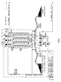
- a recycling plant includes several components that interact in order to treat the wastes in a complete and safe way and to obtain from them all the possible recovery materials, as previously mentioned. Since the diagram of fig. 1 is self-explanatory, a description of the specific connections between the various components is superfluous, but it should be noted that not all components must necessarily be present.
- the recycling plant can be generally divided into the following four sections:
- the wastes are preferably loaded on a protection screen GR101 serving the purpose of separating the materials of large size ( ⁇ 120 mm) from the rest of the materials to be washed, in order to protect the machinery that carries out the washing.
- Said screen for the rough screening can be a simple stationary screen, with manual cleaning or cleaning by tipping over of the screen by means of a hydraulic cylinder so as to drop the large materials into a relevant container, or it can be a dynamic screen, i.e. a vibrating screen.
- the materials with size ⁇ 120 mm that pass through the rough screen GR101 fall into an underlying loading hopper T101, typically made of steel sheet and sections, that may be provided or not with vibrators to facilitate the outflow of the materials to be washed.
- Said loading hopper T101 has walls with an inclination lower than 15°, so as to prevent the possibility of formation of waste bridges that would hinder the smooth outflow and therefore the constant feeding of the plant.
- the system for extracting the wastes from hopper T101 consists of a conveyor belt N101, for example with an effective width of about 800 mm, or of a pair of screws with a diameter of about 350 mm each resulting in a global width of about 700 mm.
- the width of said conveying system is such as to prevent or reduce the risk of formation of waste bridges in the loading hopper.
- the speed of the conveyor belt N101 or of the screws is adjustable by means of a frequency converter (inverter) or an electromechanical variator, so as to be able to adjust the flow rate fed to the wash plant.
- a frequency converter inverter
- an electromechanical variator electromechanical variator
- the material coming from the conveyor belt N101 is picked up by a belt feeder N102 that transports the material to a barrel washer LBT101 of the type mentioned above.
- the width of said belt feeder N102 is obviously related to the capacity of the wash plant, while its speed is preferably fixed and such as to allow the feeding of the barrel washer LBT101 at its maximum hourly processing capacity.
- a magnetic separator N103 for the separation and recovery of ferrous metals, that are picked up and discharged to a relevant container.
- the wash of the materials takes place in the barrel washer LBT101, inside which there is a turbulent mixing of the continuously loaded materials, that are washed with clean process water (coming from a storage tank of the recirculated water) that flows in counter-current inside the washer.
- the barrel washer LBT101 also receives treated and untreated water coming from other portions of the plant, and possibly sodium hydrosulphite coming from the physico-chemical treatment section.
- the barrel washer LBT101 substantially consists of a wash barrel inside which there are formed three screening zones by means of three frustoconical concentric screens connected to the wash barrel through flanges and screws, in addition to a bottom zone for the removal of inert material made up of coarse sand and gravel, and a head spillway for the outflow of the waste water containing the organic substances, fine sand and silt.
- These three frustoconical screens have screening surfaces with apertures of 2,5 mm, 8 mm and 30 mm in diameter respectively, so as to achieve the separation of silt/sand, granule, gravel and pebble.
- the separations that take place in the barrel washer LBT101 are the following:
- the above-described screening can be achieved also through means different from the frustoconical screens integrated in the barrel washer LBT101, such as vibrating screens or the like.
- the wash and screening unit could feature even a lower number of screening zones, for example using only one or two screens.
- a pipe starts from the front portion of the wash unit and reaches a vibrating drainage screen V101, with a stainless steel net typically 2,5 x 2,5 mm in mesh size, but possibly of different size, suitable to perform the separation of the organic fraction >2 mm (wood, plastic, leaves, etc.) of the waste water that contains also silt and sand.
- the waste water containing organic and inorganic material ⁇ 2 mm in size flows by gravity, through a relevant pipe, to the above-mentioned waste water collection tank VS101.
- the vibrating screen V101 is provided with nozzles that carry out a further wash of the organic material with clean process water.
- the screened material is then conveyed to a screw compactor CCL102 for the dehydration of the organic substances, that are further washed by nozzles arranged on the hopper of the compactor.
- This is a compactor capable of producing shredded organic material, with a moisture content ⁇ 30%, that can be used for composting (the compactor may be of the screw type or of any other type).
- the waste water drained from this material is conveyed to the collection tank VS101, or directly to a drain well PZ101 (fig.7).
- the collection tank VS101 is a storage tank that collects the waste water consisting of water, sand, silt and organic particles ⁇ 2 mm, coming from the vibrating screen V101, compactor CCL102 and the barrel washer LBT101.
- Tank VS101 is connected to a regulation tank VC101 that, together with a float valve VG101, provides to maintaining the minimum level sufficient for the operation of a pump P101 that draws the waste water and feeds a hydrocyclone/spirals group.
- Said tank VS101 generally having the shape of an inverted pyramid, is preferably made of steel coated with epoxide tar or coated anyway with abrasion-resistant materials.
- One or more agitators AG104, AG105 with shaft and paddles coated with abrasion-resistant material may be arranged in the tank to prevent the sedimentation of the sand and to facilitate the wash by scrubbing of the particles.
- a hydrocyclone C101 receives the waste water from tank VS101 and is used to separate the sand fraction, typically sized ⁇ 0,063 mm but in certain applications possibly of smaller size, from the silt-containing waste water that, through the top nozzle of the hydrocyclone, is conveyed to the regulation tank VC101. From here, the waste water is partly conveyed to the physico-chemical treatment section and possibly partly returned to the barrel washer LBT101.
- hydrocyclone C101 the sand particles are centrifuged and vigorously scrubbed, thus completing the washing action initiated in washer LBT101.
- the separated sand fraction (containing also organic material ⁇ 2 mm) that flows out of the bottom nozzle of the hydrocyclone is conveyed to a spirals separator SSP101.
- a friction cell CLA101 consisting of a tank internally coated with abrasion-resistant material, such as polyurethane or the like, and provided with some high-speed agitators AG101, AG102, AG103 with shaft and paddles coated with abrasion-resistant material.
- the friction cell CLA101 is shaped so as to facilitate the encounters and collisions between the sand particles, and to achieve a contact time of the water/sand/organic particles mixture not shorter than 3 minutes.
- the purpose of the friction cell CLA101 is that of facilitating the wash and decontamination of the sand particles by mutual scrubbing of the latter.
- the spirals separator SSP101 consists of a variable number of units depending on the capacity of the plant (four spirals in the illustrated example). At the top end of the separator there is arranged a load tank VCS101 for the apportionment of the feeding to the various spirals, in addition to the structure housing hydrocyclone C101 and the optional friction cell CLA101.
- the mixed fraction of water, sand and fine organic material flowing out of the bottom of hydrocyclone C101 is conveyed to the load tank VCS101 and there mixed with clean network water to rinse the sand, and then apportioned in a uniform manner in the spirals separator SSP101.
- a flowmeter FQ106 may be arranged on the network water supply line to measure and adjust the flow rate.
- the flow, along the path of each spiral, causes the separation by gravity/centrifugation of the lighter organic fractions, that arrange themselves along the outermost "flow threads", from the sand that arranges itself along the innermost "flow threads".
- the intermediate zone of the spirals there is a mixture of water, fine sand and organic particles.
- An end structure with separating baffles, located at the bottom of the spirals separator SSP101, performs the separation of the sand from the fine organic fraction, conveying each fraction to the relevant section of the final vibrating dryer.
- the intermediate fraction consisting of fine sand and organic particles, on the contrary, is directly conveyed to the waste water collection tank VS101 for the subsequent recirculation.
- the sand vibrating dryer V 103 receives the water/sand mixture coming from the inner zone of the spirals separator SSP101, and possibly also that coming from the conical screen with 2,5 mm apertures of the barrel washer LBT101, as previously mentioned.
- the vibrating dryer V103 consists of a steel frame that carries a vibrating screen box mounted on springs, whose plane is made of polyurethane with cross slots typically about 0,35 mm wide, but possibly also of other sizes. An oscillation is transmitted to the screen box by motorized vibrators, and this results in the drying and transport of the material ⁇ 2 mm.
- the sand while depositing, releases water that flows down through the slots in the plane of the vibrating box and is collected in the underlying tank VS101.
- the sand thus dried is dehydrated to a dry percentage >80% and conveyed to a relevant storage container, either directly or by means of a conveyor belt N109.
- the organic particles vibrating dryer V102 receives the water/organic particles mixture coming from the outer zone of the spirals separator SSP101.
- the vibrating dryer V102 is different from the preceding vibrating dryer V 103 in that the box plane is typically made of a stainless steel net with about 0,5 x 0,5 mm mesh size, but a net different in mesh size and material (polyurethane) may also be used.
- the organic particles ⁇ 2 mm while depositing, release water that flows down through the apertures in the plane of the vibrating box and is collected in the underlying tank VS101, while the dehydrated organic material is conveyed to a relevant storage container, either directly or by means of a conveyor belt N110.
- the physico-chemical treatment must be able to remove a great variety of pollutants and a flexible plant is therefore provided, although it must be considered that it is not necessary to destroy or precipitate all the pollutants since most of them is adsorbed on the silt and is separated anyway from the outgoing washed material.
- the physico-chemical treatment section is sized for a waste water flow rate about six times the flow rate of the wastes to be washed, and essentially consists of:
- filter SGR101 at the entrance to the physico-chemical treatment section is made necessary by the fact that the waste water leaving hydrocyclone C101, in addition to silt and heavy particles sized ⁇ 0,063 mm, also contains organic particles sized >0,10 mm.
- the removal of said organic particles is critical in that they can hardly be settled, and they would also increase the content in organic substances of the sludge, which therefore would be unsuitable for furnace recovery.
- the rotating drum filter SGR101 for the separation of the organic particles >0,25 mm that are conveyed by gravity to a relevant container.
- the reactors of unit VS102 consist of rectangular tanks formed in a monolithic structure internally coated with epoxide tar paint that resists chemicals and abrasion.
- the filtered waste water leaving filter SGR101 is conveyed to a first coagulation reactor, having an active storage such as to allow a suitable contact period and provided with a high-speed agitator AG107.
- a first coagulation reactor having an active storage such as to allow a suitable contact period and provided with a high-speed agitator AG107.
- a second reactor for the precipitation of metals which is also provided with a high-speed agitator AG108, in addition to a pH-meter PHT102.
- the hydraulic separation between the coagulation reactor and the metals precipitation reactor is achieved by means of a wall provided with nozzles that allow the flow of waste water while preventing short-circuit flows.
- a skimming device SK101 may be provided at the top of the wall to collect possible foam and/or floating substances.
- Said skimming device SK101 may be of the stationary type, consisting of a rectangular collection bin with chutes for the manual filling by means of a suitable tool, or it may consist of a rotating skimmer with manual or power drive.
- the foam and/or floating substances are conveyed by gravity to a hopper pump P114 that sends them to the line leading to a sludge storage reservoir TK107 (fig.7).
- the treated waste water leaving unit VS102 is conveyed to flocculator FL101 preferably by means of a pump P109, but it could flow to the flocculator even by gravity.
- a flowmeter FQ101 may be arranged on said line to measure and adjust the extracted flow rate.
- Flocculator FL101 is provided with an agitator AG109 and a polyelectrolyte solution is preferably metered therein.
- the tank of flocculator FL101 is preferably arranged inside sedimenter S101, so that the waste water can flow out directly into the sedimenter through suitable bottom apertures formed in the flocculator, but it could as well be an independent tank outside the sedimenter and connected thereto through a suitable pipe.
- the supernatant water leaving sedimenter S101 is conveyed to a storage tank VS103 for the purified process water (fig.8), whereas the sludge precipitated to the bottom (consisting of water, silt and pollutants precipitated in unit VS102) is conveyed to the above-mentioned sludge storage reservoir TK107 by means of a hopper pump P112, with manually adjustable flow-out rate and pause/operation timer, applied to the bottom of the sedimenter.
- a flowmeter FQ105 may also be arranged on the sludge transfer line to measure and adjust the flow rate extracted from sedimenter S101, possibly combined with substances sent to the line by pump P114.
- the reagents storage tanks are located in proper safety basins in compliance with prevailing regulations. Tanks are provided for the following reagents:
- All the reagents are metered by metering pumps with manual adjustment of the flow-out rate.
- Said station CP101 includes:
- the water required for the dissolution of the electrolyte is fed to the corresponding section of station CP101 through a network water supply pipe.
- the same pipe also supplies the spirals separator SSP101, through a relevant electrovalve EV101.
- the polyelectrolyte is metered to flocculator FL101 by a single-screw metering pump P108, with manual adjustment of the flow-out rate, or by another type of pump.
- a solution of ferric chloride or other inorganic coagulant, coming from tank TK104, is metered by means of pump P105 in the first reactor of unit VS102, to the purpose of coagulating the suspended substances.
- an organic coagulant coming from tank TK103 may be metered by means of pump P104.
- the metering is controlled by pH-meter PHT102 with automatic pH adjustment.
- a solution of flocculant polyelectrolyte is metered in flocculator FL101 by means of pump P108.
- the removal of metals is achieved by precipitation in the form of hydroxides that are removed from water by separation of the sludge.
- a solution of sodium hydroxide or calcium hydroxide, coming from tank TK101, is metered by means of pump P102 in the second reactor of unit VS102, possibly together with AQUALIFE HMP 20 or the like, coming from tank TK105 and metered by means of pump P106.
- a solution of polyelectrolyte, or other flocculant is metered in flocculator FL101 by means of pump P108 in order to obtain highly compact flakes sized 3-5 mm.
- the metering of sodium hydrosulphite is determined through lab tests and performed by the metering pump P107 with manually adjustable flow-out rate, that sends the reagent directly to the entrance of the barrel washer LBT101.
- chrome easily precipitates still in washer LBT101, and in the rest of the hydraulic circuit, as hydroxide Cr(OH) 3 since a pH ⁇ 7 or slightly alkaline is sufficient for the precipitation.
- the sludge extracted from sedimenter S101 is sent, by means of pump P112, to a storage reservoir TK107 having a conical bottom, that also acts as a thickener.
- a pump P113 At the bottom of said reservoir there is arranged a pump P113 to feed a filter press FP101 used for the mechanical dehydration of the sludge.
- the filter-pressed cake drops directly into an underlying storage container, from where it is periodically conveyed to the final disposal, while the liquor drained from the dehydrated sludge is conveyed to the storage tank VS103.
- the purified water separated in sedimenter S101 is conveyed to the storage tank VS103, and from here it is recirculated to the wash section by means of two pumps having a flow-out rate suitable for the needs:
- the purified excess water leaving through the overflow port of tank VS103 is discharged to the sewer system or as surface water, and a flowmeter FQ102 may also be provided on this discharge line.
- the watery slurry coming from the various sections of the plant is conveyed to a relevant drain well PZ101 and from here is pumped, by means of a submersible pump P115, to the entrance mouth of the barrel washer LBT101.
- the water collected in the drain well PZ101 comes from the following sources:
- submersible pump P115 preferably operates in alternation with pump P110 that feeds the barrel washer at the waste entrance side, so as not to perturb the hydraulic balance of the system since the two pumps preferably have the same flow-out rate. Furthermore, said pump P115 is suitable to raise water containing sand and gravel up to 20 mm size.
Landscapes
- Life Sciences & Earth Sciences (AREA)
- Soil Sciences (AREA)
- Engineering & Computer Science (AREA)
- Environmental & Geological Engineering (AREA)
- Separation Of Suspended Particles By Flocculating Agents (AREA)
- Processing Of Solid Wastes (AREA)
- Purification Treatments By Anaerobic Or Anaerobic And Aerobic Bacteria Or Animals (AREA)
- Electrical Discharge Machining, Electrochemical Machining, And Combined Machining (AREA)
- Treatment Of Sludge (AREA)
- Separation Of Solids By Using Liquids Or Pneumatic Power (AREA)
Applications Claiming Priority (1)
| Application Number | Priority Date | Filing Date | Title |
|---|---|---|---|
| IT001187A ITMI20051187A1 (it) | 2005-06-23 | 2005-06-23 | Impianto e processo per il riciclaggio di rifiuti provenienti da spazzamento strade depuratori acque e simili |
Publications (3)
| Publication Number | Publication Date |
|---|---|
| EP1775267A2 true EP1775267A2 (de) | 2007-04-18 |
| EP1775267A3 EP1775267A3 (de) | 2008-11-05 |
| EP1775267B1 EP1775267B1 (de) | 2010-12-22 |
Family
ID=36973915
Family Applications (1)
| Application Number | Title | Priority Date | Filing Date |
|---|---|---|---|
| EP06425045A Active EP1775267B1 (de) | 2005-06-23 | 2006-01-30 | Einrichtung und Verfahren zur Wiederverwertung von Kehrgut, Abfällen aus Wasserreinigungsgeräten und dergleichen |
Country Status (5)
| Country | Link |
|---|---|
| EP (1) | EP1775267B1 (de) |
| AT (1) | ATE492357T1 (de) |
| DE (1) | DE602006019039D1 (de) |
| ES (1) | ES2355576T3 (de) |
| IT (1) | ITMI20051187A1 (de) |
Cited By (17)
| Publication number | Priority date | Publication date | Assignee | Title |
|---|---|---|---|---|
| EP2002896A1 (de) * | 2007-06-13 | 2008-12-17 | Remat S.r.l. | System zum kalten Behandeln und Rückgewinnen von festem Stadtmüll |
| ITMI20120225A1 (it) * | 2012-02-16 | 2013-08-17 | Ecoct Tecnologie Ambientali S P A | Macchina di lavaggio a tamburo rotante |
| CN104983309A (zh) * | 2015-07-09 | 2015-10-21 | 威海迈拓思网络科技有限公司 | 一种能够废水再利用的公共饮水机及其废水再利用方法 |
| WO2017044645A1 (en) * | 2015-09-08 | 2017-03-16 | Gradiant Corporation | Systems and methods for treatment of water, such as oilfield wastewater, via chemical coagulation |
| ITUB20154865A1 (it) * | 2015-11-03 | 2017-05-03 | Ecocentro Tecnologie Ambientali S R L | Impianto mobile per la rimozione ed il trattamento di residui da vasche di impianti di depurazione e simili |
| US9969638B2 (en) | 2013-08-05 | 2018-05-15 | Gradiant Corporation | Water treatment systems and associated methods |
| US10167218B2 (en) | 2015-02-11 | 2019-01-01 | Gradiant Corporation | Production of ultra-high-density brines |
| US10245555B2 (en) | 2015-08-14 | 2019-04-02 | Gradiant Corporation | Production of multivalent ion-rich process streams using multi-stage osmotic separation |
| US10301198B2 (en) | 2015-08-14 | 2019-05-28 | Gradiant Corporation | Selective retention of multivalent ions |
| US10308537B2 (en) | 2013-09-23 | 2019-06-04 | Gradiant Corporation | Desalination systems and associated methods |
| US10308526B2 (en) | 2015-02-11 | 2019-06-04 | Gradiant Corporation | Methods and systems for producing treated brines for desalination |
| US10518221B2 (en) | 2015-07-29 | 2019-12-31 | Gradiant Corporation | Osmotic desalination methods and associated systems |
| US10689264B2 (en) | 2016-02-22 | 2020-06-23 | Gradiant Corporation | Hybrid desalination systems and associated methods |
| US11629072B2 (en) | 2018-08-22 | 2023-04-18 | Gradiant Corporation | Liquid solution concentration system comprising isolated subsystem and related methods |
| US11667549B2 (en) | 2020-11-17 | 2023-06-06 | Gradiant Corporation | Osmotic methods and systems involving energy recovery |
| US12023608B2 (en) | 2016-01-22 | 2024-07-02 | Gradiant Corporation | Hybrid desalination systems and associated methods |
| WO2024184622A1 (en) * | 2023-03-03 | 2024-09-12 | Richard Henry Coulton | Method and apparatus for separating sand from slurry |
Families Citing this family (3)
| Publication number | Priority date | Publication date | Assignee | Title |
|---|---|---|---|---|
| CN108793354A (zh) * | 2018-06-12 | 2018-11-13 | 乔静梅 | 一种砂石厂尾水环保治理工艺 |
| CN109293200B (zh) * | 2018-11-30 | 2024-09-06 | 林郁君 | 一种充气式污泥脱水设备及其工艺流程 |
| CN112844809B (zh) * | 2020-12-31 | 2022-07-29 | 中铁工程服务有限公司 | 一种集成化盾构渣土环保处理系统 |
Citations (12)
| Publication number | Priority date | Publication date | Assignee | Title |
|---|---|---|---|---|
| EP0325159A2 (de) | 1988-01-16 | 1989-07-26 | G E S U Gesellschaft Für Saubere Umwelt Mbh | Verfahren und Vorrichtung zum kontinuierlichen Reinigen von kontaminierten Böden |
| US4879048A (en) | 1987-03-19 | 1989-11-07 | Heiner Kreyenberg | Method and facility for removing sludge from water |
| DE3908185A1 (de) | 1989-03-14 | 1990-09-20 | Umwelt Gmbh Ab | Verfahren und vorrichtung zur aufbereitung kontaminierter bodenmaterialien |
| DE4034227A1 (de) | 1990-10-27 | 1992-04-30 | Kreyenberg Heiner | Verfahren und vorrichtung zum aufbereiten von ablagerungen |
| DE4326200A1 (de) | 1992-08-05 | 1994-02-10 | Porr Umwelttechnik Ag Wien | Verfahren und Vorrichtung zum kontinuierlichen Waschen von körnigen Substraten |
| EP0684088A1 (de) | 1994-03-05 | 1995-11-29 | Wilhelm Müller | Verfahren zur Reinigung von kontaminierten Materialien, insbesondere von kontaminiertem Boden sowie mobile Anlage zur Durchführung des Verfahrens |
| US5540270A (en) | 1993-06-26 | 1996-07-30 | Noell Abfall-Und Energietechnik Gmbh | Process for wet regeneration of granular bulk materials charged with impurities and pollutants |
| US5599372A (en) | 1991-08-21 | 1997-02-04 | Earth Decontaminators, Inc. | Process for removing metal contaminants from soils |
| DE19621892A1 (de) | 1996-05-31 | 1997-12-04 | Ulrich Dipl Ing Franze | Verfahren und Vorrichtung zur In-Situ-Reinigung von Spiel- und Strandsanden |
| US6007618A (en) | 1995-07-28 | 1999-12-28 | Thiele Kaolin Company | Kaolin clays which are conditioned prior to removing impurities |
| FR2790979A1 (fr) | 1999-03-19 | 2000-09-22 | Manuel Roussel | Procede et installation pour le traitement des vases |
| US20040082828A1 (en) | 2002-05-27 | 2004-04-29 | Mario Bergeron | Method of decontaminating soil |
-
2005
- 2005-06-23 IT IT001187A patent/ITMI20051187A1/it unknown
-
2006
- 2006-01-30 AT AT06425045T patent/ATE492357T1/de active
- 2006-01-30 EP EP06425045A patent/EP1775267B1/de active Active
- 2006-01-30 ES ES06425045T patent/ES2355576T3/es active Active
- 2006-01-30 DE DE602006019039T patent/DE602006019039D1/de active Active
Patent Citations (12)
| Publication number | Priority date | Publication date | Assignee | Title |
|---|---|---|---|---|
| US4879048A (en) | 1987-03-19 | 1989-11-07 | Heiner Kreyenberg | Method and facility for removing sludge from water |
| EP0325159A2 (de) | 1988-01-16 | 1989-07-26 | G E S U Gesellschaft Für Saubere Umwelt Mbh | Verfahren und Vorrichtung zum kontinuierlichen Reinigen von kontaminierten Böden |
| DE3908185A1 (de) | 1989-03-14 | 1990-09-20 | Umwelt Gmbh Ab | Verfahren und vorrichtung zur aufbereitung kontaminierter bodenmaterialien |
| DE4034227A1 (de) | 1990-10-27 | 1992-04-30 | Kreyenberg Heiner | Verfahren und vorrichtung zum aufbereiten von ablagerungen |
| US5599372A (en) | 1991-08-21 | 1997-02-04 | Earth Decontaminators, Inc. | Process for removing metal contaminants from soils |
| DE4326200A1 (de) | 1992-08-05 | 1994-02-10 | Porr Umwelttechnik Ag Wien | Verfahren und Vorrichtung zum kontinuierlichen Waschen von körnigen Substraten |
| US5540270A (en) | 1993-06-26 | 1996-07-30 | Noell Abfall-Und Energietechnik Gmbh | Process for wet regeneration of granular bulk materials charged with impurities and pollutants |
| EP0684088A1 (de) | 1994-03-05 | 1995-11-29 | Wilhelm Müller | Verfahren zur Reinigung von kontaminierten Materialien, insbesondere von kontaminiertem Boden sowie mobile Anlage zur Durchführung des Verfahrens |
| US6007618A (en) | 1995-07-28 | 1999-12-28 | Thiele Kaolin Company | Kaolin clays which are conditioned prior to removing impurities |
| DE19621892A1 (de) | 1996-05-31 | 1997-12-04 | Ulrich Dipl Ing Franze | Verfahren und Vorrichtung zur In-Situ-Reinigung von Spiel- und Strandsanden |
| FR2790979A1 (fr) | 1999-03-19 | 2000-09-22 | Manuel Roussel | Procede et installation pour le traitement des vases |
| US20040082828A1 (en) | 2002-05-27 | 2004-04-29 | Mario Bergeron | Method of decontaminating soil |
Cited By (24)
| Publication number | Priority date | Publication date | Assignee | Title |
|---|---|---|---|---|
| WO2008152672A2 (en) * | 2007-06-13 | 2008-12-18 | Remat S.R.L. | System for cold treatment and recovery of urban solid refuses |
| WO2008152672A3 (en) * | 2007-06-13 | 2010-03-18 | Remat S.R.L. | System for cold treatment and recovery of urban solid refuses |
| EP2002896A1 (de) * | 2007-06-13 | 2008-12-17 | Remat S.r.l. | System zum kalten Behandeln und Rückgewinnen von festem Stadtmüll |
| ITMI20120225A1 (it) * | 2012-02-16 | 2013-08-17 | Ecoct Tecnologie Ambientali S P A | Macchina di lavaggio a tamburo rotante |
| WO2013128310A1 (en) | 2012-02-16 | 2013-09-06 | Ecocentro Tecnologie Ambientali S.P.A. | Rotary drum washer for street sweeping waste and contaminated |
| CN104114289A (zh) * | 2012-02-16 | 2014-10-22 | 生态中心环境技术股份公司 | 用于街道清扫废物和污土的转筒清洗器 |
| US8967166B2 (en) | 2012-02-16 | 2015-03-03 | Ecocentro Tecnologie Ambientali S.P.A. | Rotary drum washer for street sweeping waste and contaminated soil |
| AU2013227378B2 (en) * | 2012-02-16 | 2017-02-02 | Ecocentro Tecnologie Ambientali S.P.A. | Rotary drum washer for street sweeping waste and contaminated soil |
| US9969638B2 (en) | 2013-08-05 | 2018-05-15 | Gradiant Corporation | Water treatment systems and associated methods |
| US10308537B2 (en) | 2013-09-23 | 2019-06-04 | Gradiant Corporation | Desalination systems and associated methods |
| US10167218B2 (en) | 2015-02-11 | 2019-01-01 | Gradiant Corporation | Production of ultra-high-density brines |
| US10308526B2 (en) | 2015-02-11 | 2019-06-04 | Gradiant Corporation | Methods and systems for producing treated brines for desalination |
| CN104983309A (zh) * | 2015-07-09 | 2015-10-21 | 威海迈拓思网络科技有限公司 | 一种能够废水再利用的公共饮水机及其废水再利用方法 |
| US11400416B2 (en) | 2015-07-29 | 2022-08-02 | Gradiant Corporation | Osmotic desalination methods and associated systems |
| US10518221B2 (en) | 2015-07-29 | 2019-12-31 | Gradiant Corporation | Osmotic desalination methods and associated systems |
| US10301198B2 (en) | 2015-08-14 | 2019-05-28 | Gradiant Corporation | Selective retention of multivalent ions |
| US10245555B2 (en) | 2015-08-14 | 2019-04-02 | Gradiant Corporation | Production of multivalent ion-rich process streams using multi-stage osmotic separation |
| WO2017044645A1 (en) * | 2015-09-08 | 2017-03-16 | Gradiant Corporation | Systems and methods for treatment of water, such as oilfield wastewater, via chemical coagulation |
| ITUB20154865A1 (it) * | 2015-11-03 | 2017-05-03 | Ecocentro Tecnologie Ambientali S R L | Impianto mobile per la rimozione ed il trattamento di residui da vasche di impianti di depurazione e simili |
| US12023608B2 (en) | 2016-01-22 | 2024-07-02 | Gradiant Corporation | Hybrid desalination systems and associated methods |
| US10689264B2 (en) | 2016-02-22 | 2020-06-23 | Gradiant Corporation | Hybrid desalination systems and associated methods |
| US11629072B2 (en) | 2018-08-22 | 2023-04-18 | Gradiant Corporation | Liquid solution concentration system comprising isolated subsystem and related methods |
| US11667549B2 (en) | 2020-11-17 | 2023-06-06 | Gradiant Corporation | Osmotic methods and systems involving energy recovery |
| WO2024184622A1 (en) * | 2023-03-03 | 2024-09-12 | Richard Henry Coulton | Method and apparatus for separating sand from slurry |
Also Published As
| Publication number | Publication date |
|---|---|
| ATE492357T1 (de) | 2011-01-15 |
| EP1775267A3 (de) | 2008-11-05 |
| DE602006019039D1 (de) | 2011-02-03 |
| EP1775267B1 (de) | 2010-12-22 |
| ES2355576T3 (es) | 2011-03-29 |
| ITMI20051187A1 (it) | 2006-12-24 |
Similar Documents
| Publication | Publication Date | Title |
|---|---|---|
| EP1775267B1 (de) | Einrichtung und Verfahren zur Wiederverwertung von Kehrgut, Abfällen aus Wasserreinigungsgeräten und dergleichen | |
| US4994179A (en) | Apparatus and process to separate and remove extraneous matter from a liquid stream | |
| KR100952752B1 (ko) | 미세토양 세척장치 및 방법 | |
| US5833863A (en) | Concrete reclamation system | |
| EP0592508B1 (de) | Verfahren und vorrichtung zur verbesserung der aufbereitung von abwasser-feststoffen, sand, müll oder dergleichen | |
| KR101995214B1 (ko) | 오염토양 선별세척 및 폐수처리정화 및 모니터링 시스템 | |
| US4855065A (en) | Apparatus and process to separate and remove extraneous matter from a liquid stream | |
| KR101782615B1 (ko) | 복합 오염 토양의 정화 시스템 및 방법 | |
| CN107127210A (zh) | 一种土壤淋洗修复系统及方法 | |
| CN104843955A (zh) | 一种油气田钻井泥浆废弃物随钻处理系统及处理方法 | |
| KR101658523B1 (ko) | 오염토양 선별 및 세척처리 정화시스템 | |
| KR20200088943A (ko) | 각종 준설토용 정화시스템 | |
| CZ365397A3 (cs) | Způsob úpravy medií a zařízení pro provádění úpravy | |
| EP0321068A1 (de) | Vorrichtung und Verfahren zum Abtrennen und Entfernen von Fremdstoffen aus einem Flüssigkeitsstrom | |
| US4769154A (en) | Chlorine oxidation waste water treatment method | |
| GB2290985A (en) | An Apparatus and method for purifying water | |
| CN108409073A (zh) | 通沟污泥处理方法 | |
| CN204644081U (zh) | 一种油气田钻井泥浆废弃物随钻处理系统 | |
| KR101929272B1 (ko) | 복합 오염 토양 정화 시스템 | |
| KR980000658A (ko) | 음식물쓰레기와 분뇨의 퇴비 및 사료화 시스템 | |
| EP2723499A1 (de) | Verfahren und vorrichtung zur grundaschebehandlung | |
| US5302289A (en) | Material separation process and apparatus | |
| KR20020096274A (ko) | 준설토의 모래선별 및 세척수 정수시스템 | |
| RU2328454C2 (ru) | Станция водоподготовки | |
| KR102573143B1 (ko) | 고자력분리기가 구비된 복합 오염토양 정화 및 자원화 시스템 |
Legal Events
| Date | Code | Title | Description |
|---|---|---|---|
| PUAI | Public reference made under article 153(3) epc to a published international application that has entered the european phase |
Free format text: ORIGINAL CODE: 0009012 |
|
| AK | Designated contracting states |
Kind code of ref document: A2 Designated state(s): AT BE BG CH CY CZ DE DK EE ES FI FR GB GR HU IE IS IT LI LT LU LV MC NL PL PT RO SE SI SK TR |
|
| AX | Request for extension of the european patent |
Extension state: AL BA HR MK YU |
|
| PUAL | Search report despatched |
Free format text: ORIGINAL CODE: 0009013 |
|
| AK | Designated contracting states |
Kind code of ref document: A3 Designated state(s): AT BE BG CH CY CZ DE DK EE ES FI FR GB GR HU IE IS IT LI LT LU LV MC NL PL PT RO SE SI SK TR |
|
| AX | Request for extension of the european patent |
Extension state: AL BA HR MK YU |
|
| RIC1 | Information provided on ipc code assigned before grant |
Ipc: B03B 9/00 20060101ALI20080930BHEP Ipc: C02F 11/00 20060101AFI20070314BHEP Ipc: B03B 5/00 20060101ALI20080930BHEP Ipc: B03B 9/06 20060101ALI20080930BHEP Ipc: B09C 1/02 20060101ALI20080930BHEP |
|
| 17P | Request for examination filed |
Effective date: 20090504 |
|
| AKX | Designation fees paid |
Designated state(s): AT BE BG CH CY CZ DE DK EE ES FI FR GB GR HU IE IS IT LI LT LU LV MC NL PL PT RO SE SI SK TR |
|
| RIC1 | Information provided on ipc code assigned before grant |
Ipc: B09C 1/02 20060101AFI20100217BHEP |
|
| GRAJ | Information related to disapproval of communication of intention to grant by the applicant or resumption of examination proceedings by the epo deleted |
Free format text: ORIGINAL CODE: EPIDOSDIGR1 |
|
| GRAP | Despatch of communication of intention to grant a patent |
Free format text: ORIGINAL CODE: EPIDOSNIGR1 |
|
| GRAP | Despatch of communication of intention to grant a patent |
Free format text: ORIGINAL CODE: EPIDOSNIGR1 |
|
| GRAS | Grant fee paid |
Free format text: ORIGINAL CODE: EPIDOSNIGR3 |
|
| GRAA | (expected) grant |
Free format text: ORIGINAL CODE: 0009210 |
|
| AK | Designated contracting states |
Kind code of ref document: B1 Designated state(s): AT BE BG CH CY CZ DE DK EE ES FI FR GB GR HU IE IS IT LI LT LU LV MC NL PL PT RO SE SI SK TR |
|
| REG | Reference to a national code |
Ref country code: GB Ref legal event code: FG4D |
|
| REG | Reference to a national code |
Ref country code: CH Ref legal event code: EP |
|
| REG | Reference to a national code |
Ref country code: CH Ref legal event code: NV Representative=s name: RIEDERER HASLER & PARTNER PATENTANWAELTE AG |
|
| REG | Reference to a national code |
Ref country code: IE Ref legal event code: FG4D |
|
| REF | Corresponds to: |
Ref document number: 602006019039 Country of ref document: DE Date of ref document: 20110203 Kind code of ref document: P |
|
| REG | Reference to a national code |
Ref country code: DE Ref legal event code: R096 Ref document number: 602006019039 Country of ref document: DE Effective date: 20110203 |
|
| REG | Reference to a national code |
Ref country code: ES Ref legal event code: FG2A Ref document number: 2355576 Country of ref document: ES Kind code of ref document: T3 Effective date: 20110329 |
|
| REG | Reference to a national code |
Ref country code: NL Ref legal event code: VDEP Effective date: 20101222 |
|
| PG25 | Lapsed in a contracting state [announced via postgrant information from national office to epo] |
Ref country code: LT Free format text: LAPSE BECAUSE OF FAILURE TO SUBMIT A TRANSLATION OF THE DESCRIPTION OR TO PAY THE FEE WITHIN THE PRESCRIBED TIME-LIMIT Effective date: 20101222 |
|
| REG | Reference to a national code |
Ref country code: CH Ref legal event code: PFA Owner name: ECOCENTRO TECNOLOGIE AMBIENTALI S.P.A. Free format text: ECOCENTRO TECNOLOGIE AMBIENTALI S.R.L.#VIA MAESTRI DEL LAVORO 6#24020 GORLE (BG) (IT) -TRANSFER TO- ECOCENTRO TECNOLOGIE AMBIENTALI S.P.A.#VIA MAESTRI DEL LAVORO 6#24020 GORLE (BG) (IT) |
|
| RAP2 | Party data changed (patent owner data changed or rights of a patent transferred) |
Owner name: ECOCENTRO TECNOLOGIE AMBIENTALI S.P.A. |
|
| LTIE | Lt: invalidation of european patent or patent extension |
Effective date: 20101222 |
|
| PG25 | Lapsed in a contracting state [announced via postgrant information from national office to epo] |
Ref country code: SI Free format text: LAPSE BECAUSE OF FAILURE TO SUBMIT A TRANSLATION OF THE DESCRIPTION OR TO PAY THE FEE WITHIN THE PRESCRIBED TIME-LIMIT Effective date: 20101222 Ref country code: SE Free format text: LAPSE BECAUSE OF FAILURE TO SUBMIT A TRANSLATION OF THE DESCRIPTION OR TO PAY THE FEE WITHIN THE PRESCRIBED TIME-LIMIT Effective date: 20101222 Ref country code: CY Free format text: LAPSE BECAUSE OF FAILURE TO SUBMIT A TRANSLATION OF THE DESCRIPTION OR TO PAY THE FEE WITHIN THE PRESCRIBED TIME-LIMIT Effective date: 20101222 Ref country code: FI Free format text: LAPSE BECAUSE OF FAILURE TO SUBMIT A TRANSLATION OF THE DESCRIPTION OR TO PAY THE FEE WITHIN THE PRESCRIBED TIME-LIMIT Effective date: 20101222 Ref country code: BG Free format text: LAPSE BECAUSE OF FAILURE TO SUBMIT A TRANSLATION OF THE DESCRIPTION OR TO PAY THE FEE WITHIN THE PRESCRIBED TIME-LIMIT Effective date: 20110322 Ref country code: LV Free format text: LAPSE BECAUSE OF FAILURE TO SUBMIT A TRANSLATION OF THE DESCRIPTION OR TO PAY THE FEE WITHIN THE PRESCRIBED TIME-LIMIT Effective date: 20101222 |
|
| REG | Reference to a national code |
Ref country code: DE Ref legal event code: R081 Ref document number: 602006019039 Country of ref document: DE Owner name: ECOCENTRO TECNOLOGIE AMBIENTALI S.P.A., IT Free format text: FORMER OWNER: ECOCENTRO TECNOLOGIE AMBIENTALI S.R.L., GORLE, IT Effective date: 20110303 |
|
| PG25 | Lapsed in a contracting state [announced via postgrant information from national office to epo] |
Ref country code: CZ Free format text: LAPSE BECAUSE OF FAILURE TO SUBMIT A TRANSLATION OF THE DESCRIPTION OR TO PAY THE FEE WITHIN THE PRESCRIBED TIME-LIMIT Effective date: 20101222 Ref country code: GR Free format text: LAPSE BECAUSE OF FAILURE TO SUBMIT A TRANSLATION OF THE DESCRIPTION OR TO PAY THE FEE WITHIN THE PRESCRIBED TIME-LIMIT Effective date: 20110323 Ref country code: IS Free format text: LAPSE BECAUSE OF FAILURE TO SUBMIT A TRANSLATION OF THE DESCRIPTION OR TO PAY THE FEE WITHIN THE PRESCRIBED TIME-LIMIT Effective date: 20110422 Ref country code: EE Free format text: LAPSE BECAUSE OF FAILURE TO SUBMIT A TRANSLATION OF THE DESCRIPTION OR TO PAY THE FEE WITHIN THE PRESCRIBED TIME-LIMIT Effective date: 20101222 Ref country code: PT Free format text: LAPSE BECAUSE OF FAILURE TO SUBMIT A TRANSLATION OF THE DESCRIPTION OR TO PAY THE FEE WITHIN THE PRESCRIBED TIME-LIMIT Effective date: 20110422 Ref country code: BE Free format text: LAPSE BECAUSE OF FAILURE TO SUBMIT A TRANSLATION OF THE DESCRIPTION OR TO PAY THE FEE WITHIN THE PRESCRIBED TIME-LIMIT Effective date: 20101222 |
|
| PG25 | Lapsed in a contracting state [announced via postgrant information from national office to epo] |
Ref country code: RO Free format text: LAPSE BECAUSE OF FAILURE TO SUBMIT A TRANSLATION OF THE DESCRIPTION OR TO PAY THE FEE WITHIN THE PRESCRIBED TIME-LIMIT Effective date: 20101222 Ref country code: SK Free format text: LAPSE BECAUSE OF FAILURE TO SUBMIT A TRANSLATION OF THE DESCRIPTION OR TO PAY THE FEE WITHIN THE PRESCRIBED TIME-LIMIT Effective date: 20101222 Ref country code: MC Free format text: LAPSE BECAUSE OF NON-PAYMENT OF DUE FEES Effective date: 20110131 Ref country code: NL Free format text: LAPSE BECAUSE OF FAILURE TO SUBMIT A TRANSLATION OF THE DESCRIPTION OR TO PAY THE FEE WITHIN THE PRESCRIBED TIME-LIMIT Effective date: 20101222 Ref country code: PL Free format text: LAPSE BECAUSE OF FAILURE TO SUBMIT A TRANSLATION OF THE DESCRIPTION OR TO PAY THE FEE WITHIN THE PRESCRIBED TIME-LIMIT Effective date: 20101222 |
|
| REG | Reference to a national code |
Ref country code: IE Ref legal event code: MM4A |
|
| PLBE | No opposition filed within time limit |
Free format text: ORIGINAL CODE: 0009261 |
|
| STAA | Information on the status of an ep patent application or granted ep patent |
Free format text: STATUS: NO OPPOSITION FILED WITHIN TIME LIMIT |
|
| PG25 | Lapsed in a contracting state [announced via postgrant information from national office to epo] |
Ref country code: DK Free format text: LAPSE BECAUSE OF FAILURE TO SUBMIT A TRANSLATION OF THE DESCRIPTION OR TO PAY THE FEE WITHIN THE PRESCRIBED TIME-LIMIT Effective date: 20101222 |
|
| 26N | No opposition filed |
Effective date: 20110923 |
|
| REG | Reference to a national code |
Ref country code: DE Ref legal event code: R097 Ref document number: 602006019039 Country of ref document: DE Effective date: 20110923 |
|
| PG25 | Lapsed in a contracting state [announced via postgrant information from national office to epo] |
Ref country code: IE Free format text: LAPSE BECAUSE OF NON-PAYMENT OF DUE FEES Effective date: 20110130 |
|
| PG25 | Lapsed in a contracting state [announced via postgrant information from national office to epo] |
Ref country code: LU Free format text: LAPSE BECAUSE OF NON-PAYMENT OF DUE FEES Effective date: 20110130 |
|
| PG25 | Lapsed in a contracting state [announced via postgrant information from national office to epo] |
Ref country code: TR Free format text: LAPSE BECAUSE OF FAILURE TO SUBMIT A TRANSLATION OF THE DESCRIPTION OR TO PAY THE FEE WITHIN THE PRESCRIBED TIME-LIMIT Effective date: 20101222 |
|
| PG25 | Lapsed in a contracting state [announced via postgrant information from national office to epo] |
Ref country code: HU Free format text: LAPSE BECAUSE OF FAILURE TO SUBMIT A TRANSLATION OF THE DESCRIPTION OR TO PAY THE FEE WITHIN THE PRESCRIBED TIME-LIMIT Effective date: 20101222 |
|
| REG | Reference to a national code |
Ref country code: FR Ref legal event code: PLFP Year of fee payment: 11 |
|
| REG | Reference to a national code |
Ref country code: FR Ref legal event code: PLFP Year of fee payment: 12 |
|
| REG | Reference to a national code |
Ref country code: FR Ref legal event code: PLFP Year of fee payment: 13 |
|
| PGFP | Annual fee paid to national office [announced via postgrant information from national office to epo] |
Ref country code: ES Payment date: 20240223 Year of fee payment: 19 |
|
| PGFP | Annual fee paid to national office [announced via postgrant information from national office to epo] |
Ref country code: AT Payment date: 20240122 Year of fee payment: 19 |
|
| PGFP | Annual fee paid to national office [announced via postgrant information from national office to epo] |
Ref country code: DE Payment date: 20240119 Year of fee payment: 19 Ref country code: CH Payment date: 20240201 Year of fee payment: 19 Ref country code: GB Payment date: 20240119 Year of fee payment: 19 |
|
| PGFP | Annual fee paid to national office [announced via postgrant information from national office to epo] |
Ref country code: IT Payment date: 20240108 Year of fee payment: 19 Ref country code: FR Payment date: 20240124 Year of fee payment: 19 |