EP1774199B1 - Rolling traction planetary drive - Google Patents
Rolling traction planetary drive Download PDFInfo
- Publication number
- EP1774199B1 EP1774199B1 EP05773470.9A EP05773470A EP1774199B1 EP 1774199 B1 EP1774199 B1 EP 1774199B1 EP 05773470 A EP05773470 A EP 05773470A EP 1774199 B1 EP1774199 B1 EP 1774199B1
- Authority
- EP
- European Patent Office
- Prior art keywords
- planet
- case
- inner ring
- ramp
- traction
- Prior art date
- Legal status (The legal status is an assumption and is not a legal conclusion. Google has not performed a legal analysis and makes no representation as to the accuracy of the status listed.)
- Expired - Lifetime
Links
Images



Classifications
-
- F—MECHANICAL ENGINEERING; LIGHTING; HEATING; WEAPONS; BLASTING
- F16—ENGINEERING ELEMENTS AND UNITS; GENERAL MEASURES FOR PRODUCING AND MAINTAINING EFFECTIVE FUNCTIONING OF MACHINES OR INSTALLATIONS; THERMAL INSULATION IN GENERAL
- F16H—GEARING
- F16H13/00—Gearing for conveying rotary motion with constant gear ratio by friction between rotary members
- F16H13/06—Gearing for conveying rotary motion with constant gear ratio by friction between rotary members with members having orbital motion
Definitions
- the present invention relates generally to mechanical power management systems and specifically to rolling traction planetary drive systems.
- Planetary gear systems have found significant use in many applications including automatic car transmissions and industrial equipment, as well as many others.
- Planetary gear systems are made of a central sun gear that rotates about a longitudinal axis and that is surrounded by one or more sets of planet gears.
- the planet gears in a plane surround the sun gear with each of their respective peripheral edges engaging the sun gear at its outer surface and.
- a ring gear surrounds the planet gears and engages the peripheral edge of each of the planet gears at their radially outermost point from the longitudinal axis.
- Each of the planet gears rotates about a planet shaft that forms its own axis.
- a planet carrier holds all of the planet shafts in their alignment and spatial distribution about the sun gear.
- the planet carrier is typically a disc or some other structure that is mounted coaxially about the longitudinal axis and can be capable of rotating about the longitudinal axis.
- a planetary gear set can provide various levels of rotational speed reduction or increase and is very flexible.
- rotational torque input can be through any one or combination of the planet carrier, the ring gear or the sun gear and the output can be out of any one or combinations of these components as well.
- an input can be provided to the planet carrier, the ring gear can be fixed so that it does not rotate, and the output can be taken out of the sun gear.
- the increase in speed, or transmission ratio is a function of the ratio of the circumference of the ring gear to that of the planet gears; the planetary gear or "PG" ratio for this configuration.
- a planetary gear set it would be beneficial for a planetary gear set to achieve any or all of the following as well; a large speed change, the ability to produce any speed change ratio, the capacity for a very high rotational speed, a low manufacturing cost, long component life, flexible packaging for a wide variety of applications, or any combination of these.
- JP-58-065361-A discloses a traction-drive system having the features of the pre-characterizing portion of Claim 1.
- EP-0638741-A1 discloses a planetary type traction roller transmission which has a high transmission ratio and an axial force generator.
- a planetary traction-drive system operating about a longitudinal axis comprises: an idler positioned coaxially about the longitudinal axis, a plurality of generally disc-shaped planet rollers distributed about and in contact with the idler, the planet rollers distributed in a plane that is orthogonal to the longitudinal axis, and the planet rollers each rotating about a respective planet axis; an inner ring positioned coaxially about the longitudinal axis and that contacts each of the planet rollers; and a tubular case positioned coaxially about the longitudinal axis that at least partially encloses and surrounds the idler, the inner ring and the planet rollers and that has a case ring on its inner surface that contacts each of the planet rollers.
- Each of the planet axes is parallel to the longitudinal axis.
- the inner ring contacts each of the planet rollers at a first radius from the longitudinal axis
- the case ring contacts each of the planet rollers at a second radius from the longitudinal axis
- the idler contacts each of the planet rollers at a third radius from the longitudinal axis.
- the first radius, the second radius and the third radius are all different from one another.
- Each of the planet rollers has a first contact surface, a second contact surface, and a third contact surface, and each of the planet rollers is adapted to rotate about a generally cylindrical axle that forms a planet axis that is generally parallel to the longitudinal axis, and the first contact surface of each planet roller is angled with respect to its respective axis.
- the first radius is less than the second radius.
- Some embodiments of the planetary traction-drive system further comprise a cage adapted to at least maintain an axial alignment and radial position of the planet axes.
- Some embodiments further comprise a case cap that engages with the case to partially enclose the cage, idler, planet rollers and the inner ring.
- each planet roller is angled with respect to its respective planet axis. In yet other embodiments, the idler contact surface of each planet roller is generally parallel to its planet axis.
- the case ring is attached to a generally tubular case that at least partially surrounds the remaining components of the traction-drive system and, in some of these embodiments, the case is stationary.
- the traction-drive system further comprises an axial force generator.
- the axial force generator of some embodiments comprises a ramp disc positioned adjacent to the inner ring on a side opposite from the planet rollers and that is adapted to rotate about the longitudinal axis and that has a first side facing the planet rollers and a second side facing away from the planet rollers, a set of ramps distributed about the radially outward edge of the first side of the ramp disc, and a set of ramp bearings, each ramp bearing located between the ramp disc and the inner ring and adapted to ride along a respective one of the set of ramps.
- the set of ramps and the ramp bearings cooperate to convert torque input to the ramp disc into torque and axial force that are both transferred to the inner ring.
- the axial force generator comprises at least one spring.
- the spring of some embodiments comprises a Belleville spring.
- Figure 1a is a schematic cross-sectional view of one embodiment of a rolling traction planetary drive.
- Figure 1b is an exploded view of the embodiment illustrated in Figure 1a .
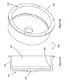
- Figure 2a is a cross-sectional side view of the case of the embodiment illustrated in Figure 1a .
- Figure 2b is an isometric view of the case of the embodiment illustrated in Figure 1a .
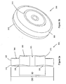
- Figure 3a is a cross-sectional side view of a power roller of the embodiment illustrated in Figure 1a .
- Figure 3b is an isometric view of a power roller of the embodiment illustrated in Figure 1a .
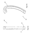
- Figure 4a is a cross-sectional side view of the inner ring of the embodiment illustrated in Figure 1 .
- Figure 4b is an isometric view of the inner ring of the embodiments illustrated in Figure 1 .
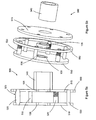
- Figure 5a is a cross-sectional side view of the cage of the embodiment illustrated in Figure 1a .
- Figure 5b is an isometric exploded view of the cage of the embodiment of Figure 1a .
- Figure 6a is a cross-sectional side view of the ramp disc assembly of the embodiment of Figure 1a .
- Figure 6b is an isometric exploded view of the ramp disc assembly of the embodiment of Figure 1b .
- Figure 7 is a schematic diagram illustrating the kinematic relationships of the rotating components of the planetary drive of Figures 1a and 1b .
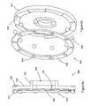
- FIGS 1a and 1b illustrate one embodiment of a rolling traction planetary drive 100 that can be used to replace traditional planetary gear sets.
- the planetary drive 100 is somewhat analogous in some ways to a traditional planetary gear set.
- An idler 110 replaces the sun gear of the traditional planetary gear set and is positioned coaxially about a central shaft 120.
- the idler 110 of this embodiment is a short tube having an inside diameter and an outer surface.
- the idler 110 of this embodiment is fitted around a central shaft 120, which forms a longitudinal axis for the planetary drive 100.
- the idler 110 of this embodiment is surrounded by and supports a plurality of planet rollers 300, which are analogous to the planet gears of the traditional planetary gear set.
- the planet rollers 300 orbit the idler 110 and roll along the outer surface of the idler 110 at their radially inward peripheral edge, with respect to the longitudinal axis.
- the ring gear of the traditional planetary gear set is replaced in this embodiment by a surrounding case 200.
- the case 200 which along with all of the components will be described further below, surrounds the planet rollers 300 and idler 110.
- a case cap 150 engages with the case 200 to partially enclose and encapsulate the internal components of the planetary drive 100.
- the case cap 150 is a flat disc having a hole formed at its center that is coaxial with the central shaft 120, although it is not necessarily positioned along the central shaft 120.
- the case 200 of the illustrated embodiment is fixed to the case cap 150 with a plurality of case fasteners 115.
- the case fasteners 115 can be any type of fastener or fastening mechanism that can be used to affix the case 200 to the case cap 150.
- case fasteners 115 are not used and the case is adapted with a fastening interlock that is accepted by and engages with corresponding structure on the case cap 150.
- the case cap 150 of the illustrated embodiment includes fastener holes 117 that allow the planetary drive 100 to be attached to the equipment or vehicle on which the planetary drive 100 is utilized. Any standard fastening devices or method can be used to mount the planetary drive 100, and the fasteners suggested by this illustrated embodiment are only an example.
- the planet rollers 300 of the illustrated embodiment roll along a case ring (illustrated as 250 in Figure 2 ) at their respective radially outermost points with respect to the longitudinal axis, as they rotate.
- the planet rollers 300 orbit the idler 110, and the case 200 is fixed and therefore does not rotate.
- the case 200 rotates and the planet rollers 300 can remain in their angular positions about the idler 110, while in yet other embodiments, the case 200 rotates and the planet rollers 300 are allowed to orbit the central shaft 120.
- the planet rollers 300 each rotate about their own respective axes, which are formed by roller axles 520.
- the roller axles 520 are generally cylindrical shafts that extend through the planet rollers 300 and align the planet rollers 300 with respect to the longitudinal axis.
- the roller axles 520 of some embodiments are parallel to the longitudinal axis formed by the central shaft 120 while in other embodiments, the roller axles 520 are not parallel to the longitudinal axis and the roller axles 520 will be described in further detail below with respect to Figure 5 below.
- the roller axles 520 are maintained in their respective positions and orientations about the central shaft 120 by a pair of stator discs 510, 515.
- stator discs 510, 515 which will be described in more detail below with respect to Figure 5 are generally flat discs mounted orthogonal to and coaxial about the central shaft 120. In some embodiments the stator discs 510, 515 rotate about the central shaft 120 while in other embodiments, the stator discs 510, 515 are stationary and do not rotate. In some embodiments, relative rotational motion between the stator discs 510, 515 and the central shaft 120 is allowed and facilitated by stator bearings 130, 135.
- the stator bearings 130, 135 in the illustrated embodiment are radial bearings, although combination radial-thrust bearings and multiple bearings are used in other embodiments.
- stator discs 510, 515 are also held in alignment with one another by cylindrical stator spacers 530.
- the stator spacers 530, stator discs 510, 515, and the roller axles 520 form the cage 500 of the planetary drive 100.
- the cage 500 rotates about the central shaft 120; however, in other embodiments the cage 500 is stationary and does not rotate about the central shaft 120.
- the central shaft 120 and the case 200 are maintained in their alignment and positioning with respect to one another by a case bearing 125.
- the case bearing 125 of the illustrated embodiment is a radial bearing; however, in other embodiments a combination radial-thrust bearing or multiple bearings are used.
- the stator discs 510, 515 are maintained in their respective radial positions about the central shaft 120 by stator bearings 130, 135 in the illustrated embodiment. However, in other embodiments the stator discs 510, 515 are fixed to the central shaft 120.
- a tubular cage driver 540 extends from a radially inward portion of one of the stator discs 510, 515.
- the cage driver 540 extends toward the case cap 150, however in other embodiments, no cage driver 540 is utilized and in yet other embodiments, the cage driver 540 extends toward or beyond the case 200.
- a driver bearing 140 provides for radial positioning and alignment of the cage driver 540 and the central shaft 120.
- the driver bearing 140 is a radial bearing, however in other embodiments the driver bearing 140 is a combination radial-thrust bearing or other type of bearing or combination of bearings.
- the planet rollers 300 contact an inner ring 400 at a third point on each respective planet roller 300.
- the inner ring 400 of the illustrated embodiment is a ring that is positioned coaxially about the central shaft 120 and is positioned axially between the planet rollers 300 and the case cap 150.
- the inner ring 400 which will be described in further detail below, transmits torque supplied into the planet drive 100 to the planet rollers 300. Torque is transmitted to the inner ring 400 by a ramp disc 600 assembly.
- the ramp disc assembly 600 of the illustrated embodiment which will be described in detail below, is situated adjacent to the inner ring 400 and drives the inner ring 400 and provides an amount of axial force to the inner ring 400 to increase the traction between the rolling components of the planetary drive 100.
- the ramp disc assembly 600 includes a ramp disc 610, which is generally a flat disc positioned coaxially about the central shaft 120 and is positioned axially between the inner ring 400 and the case cap 150, and a set of ramp bearings 620.
- the ramp disc 610 of the illustrated embodiment has a central bore 605 formed at its center and has a tubular ramp driver 650 that extends from the central bore 605 toward and through the case cap 150.
- An outer driver bearing 145 fits within the ramp driver 650 and maintains the radial position and alignment of the ramp disc 610 and the cage driver 540.
- the outer driver bearing 145 of the illustrated embodiment is a radial bearing, however a combination radial thrust bearing or other bearings and combinations of bearings are used in other embodiments.
- the illustrated embodiment utilizes a case cap thrust bearing 155 to maintain the axial position of the ramp disc 610 with respect to the case cap 150 and to absorb the axial thrust developed by the ramp disc 610.
- the case cap 150 has a thrust race 157 formed on its side facing the ramp disc 610 that is adapted to house the case cap thrust bearing 155.
- the thrust race 157 is mounted on or otherwise affixed to the case cap 150.
- the illustrated embodiment also utilizes a case cap radial bearing 160 positioned axially and radially between the case cap 150 and the ramp driver 650.
- the case cap radial bearing 160 can be a radial bearing, a thrust bearing, a combination radial-thrust bearing, or multiple bearings.
- the case 200 of the illustrated embodiment has a generally tube-shaped body 220 and has an open end 202 on one side and a closed end 204 on the opposing side.
- the open end 202 mates with the case cap 150 to enclose the internal components of the planetary drive 100.
- a mating face 210 is provided to attach the case 200 to the case cap 150.
- the mating face 210 is a flange extending radially outward from the open end 202 of the case 200.
- the mating face 210 of this embodiment has holes 215 that allow fasteners 115 to attach the case 200 to the case cap 150.
- the mating face 210 has a set of threads formed on its outer edge that mates with and engages a corresponding set of threads formed on the case cap 150 so that the case 200 can be threaded onto the case cap 150.
- the case cap 150 of many such embodiments has a recess into which the case 200 fits.
- a central hole 230 is formed in the closed end 204 of the case 200 to pass the central shaft 120. As described above, the central shaft 120 of the illustrated embodiment is free to rotate with respect to the case 200. However, in other embodiments, the case 200 can be fixed to the central shaft 120.
- the case 200 has a case ring 250 formed on its inner surface.
- the case ring 250 of the illustrated embodiment is an angled surface mounted on the inner portion of the body 220 near the closed end 204.
- the case ring 250 is angled in this embodiment and the planet rollers 300 are held by axial force in rolling traction with the case ring 250.
- the angle of inclination of the case ring 250 for any longitudinal plane of the case 200 is the angle between the inner surface of the body 210, assumed in many embodiments to be parallel to the longitudinal axis of the planetary drive 100, and the rolling surface of the case ring 250 and can be any angle ranging from zero to ninety degrees.
- the angle of inclination of the case ring 250 ranges from one and forty-five degrees, while in other embodiments the range is from one to thirty, 20 or 15 degrees. In some embodiments, the angle of inclination of the case ring 250 ranges from two to ten degrees. In some embodiments the angle of inclination is any of 2, 3, 4, 5, 6, 7, 8, 9 or 10 degrees, while in certain embodiments, the angle is between 5 and 6 degrees. As will be described below, the angle of the case contact surface 315 of the planet rollers 300 that contacts the case ring 250 is complimentary to the angle of the case ring 250.
- FIGs 3a and 3b illustrate an embodiment of the planet rollers 300 of the planetary drive embodiment of Figures 1a and 1b .
- the planet roller 300 illustrated in this embodiment is generally shaped like a disc having a first side facing the case cap 150, a second side facing the case 200, an outer diameter OD, a central bore 325 and a lip or inner contact surface 310 that extends axially from the first side of the planet roller 300 from an inner diameter ID between the central bore 325 and the outer diameter OD.
- the planet roller 300 rotates about the central bore 325, and the central bore 325 houses the planet shaft 520, described further below, which maintains the radial position and axial alignment of the planet roller 300.
- the inner contact surface 310 mates with and is driven by the inner ring 400.
- the inner ring 400 provides both axial contact force and rotational torque to the inner contact surface 310 of the planet roller 300.
- Case and idler contact surfaces 315, 320 are formed on the outer diameter of the planet roller 300 of the illustrated embodiment.
- the case contact surface 315 is formed at a different diameter than the OD such as by a second lip that is radially inward from the OD and is mounted similarly to the inner contact surface 310.
- the case ring 250 is located at a corresponding position on the case 200 to engage with the case contact surface 315.
- the case contact surface 315 of the illustrated embodiment is an angled portion of the radially outer edge of the planet roller 300 near the side opposite of the inner contact surface 310.
- the outer edge of the planet roller 300 is a widened surface housing both the case and idler contact surfaces 315, 320.
- the case contact surface 315 is at an angle with respect to the central shaft 120.
- the idler contact surface 320 is generally the remainder of the outer edge of the planet roller 300 and is substantially parallel to the central shaft 120. The idler contact surface 320 rolls along the outer surface of the idler 110.
- the inner contact surface 310 is positioned at an angle of inclination from the axis formed by the central shaft 120 of Figure 1a .
- the inner contact surface 310 is angled in orientation starting from its outer edge and moving toward the axial centerline of the planet roller 300.
- the angle of inclination of the inner contact surface 310 can be any of the angles listed above for the case ring 250 with respect to its respective orientation.
- the case contact surface 315 is complimentary to the angled case ring 250.
- the case contact surface 315 is parallel to the case ring 250, while in other embodiments the surfaces are slightly misaligned to allow for conformation of the surfaces when axial force is applied.
- weight is reduced through the use of recesses 330, 340, 350.
- the illustrated recesses 330, 340, 350 are radiused cutouts from the radial sides of the planet roller.
- the recesses 330, 340, 350 reduce the weight of the planet rollers 300 and therefore reduce the inertia developed as the planet rollers 300 rotate.
- weight is reduced by utilizing spokes for the radial support of the planet rollers 300 instead of the solid discs used in the illustrated embodiment.
- spin is reduced in planetary drive 100 through the use of the parallel surfaces of the idler 110 and the idler contact surface 320.
- Spin can be considered an efficiency loss caused by transverse forces in the contact patches of two rolling surfaces.
- the transverse forces on each surface are a result of varying rates of relative rotation occurring at various positions in the contact patch that are each at different radii of rotation.
- a moment or spin is developed in the contact patch. This moment or spin results in a loss of energy transferred out of the drive and therefore reduced efficiency.
- spin is nearly if not fully eliminated because the radii from the longitudinal axis of substantially all of the points in the contact patch are equal. Because all of the contact patch points are of equal radii from the axis of rotation, even under some elastic deformation, a highly efficient transfer of power is obtained.
- the outer surface of the idler 110 is substantially of one diameter along its length that is in contact with the idler contact surface 320. Furthermore, the idler contact surface 320 extends axially along a generally constant radius so that as the idler contact surface 320 contacts the idler 110, the contact patch is in the general form of a line. All of the contact points in the contact patch are substantially at the same rotational radius as all of the other contact points on that component, so that there is little to no variance in rotational speed and therefore, little to no spin is generated.
- the inner ring 400 of the illustrated embodiment transmits torque and axial force to the inner contact surface 320 of the planet rollers 300.
- the inner ring 400 is a ring that is positioned coaxially about the axis of planetary drive 100 formed by the central shaft 120 and has a first side that contacts the planet rollers 300 and a second side that is driven by the ramp disc 800.
- the first side has a ring drive surface 410 that faces radially inward and is complimentary to the inner contact surface 310 of the planet rollers 300.
- the ring drive surface 410 is oriented at an angle from the axis of the central shaft 120 and thus the planetary drive 100, which can be called an input angle.
- the input angle can be any of the angles described for the case ring 250 and is complimentary to the angle of the inner contact surface 310 of the planet rollers 300 in order to most efficiently transfer torque from the inner ring 400 to the planet rollers 400.
- the second side of the inner ring 400 has an inner ring race 420 that guides and contains the ramp bearings 810 as the ramp bearings 810 apply torque and axial force to the inner ring 400.
- the illustrated inner ring race 420 is formed into or is integral with the inner ring 400, however in other embodiments, the inner ring race 420 is attached to the inner ring 400.
- a set of ramps that is complimentary to the ramps (described below) of the ramp disc 800 is formed on the inner ring 400. Such ramps produce axial force that varies with changes in the amount of input torque provided to the planetary drive 100.
- these ramps provide for the optimal amount of axial force through the system to maximize efficiency and prevent slippage of the inner ring 400 and planet rollers 300.
- the optimal amount of axial force in some embodiments is that amount of axial force that provides a friction force between the ramp bearings 810 and the inner ring 400 sufficient to transmit all of the torque to the inner ring 400 without any slipping between the ramp bearings 810 and the inner ring 400.
- the ramp bearings 810 are not implemented and the ramp disc 800 directly drives the ramps of the inner ring 400.
- the cage 500 of the planetary drive 100 is formed, as stated above, by first and second stator discs 510, 515, respectively, a plurality of planet shafts 520, and a plurality of stator spacers 530.
- the first and second stator discs 510 are relatively flat discs having a bore and their centers and are positioned coaxially about the central shaft 120.
- the stator discs 510, 515 are maintained in their respective radial positions about an axial alignment with the central shaft 120 by stator bearings 130, 135, and in other embodiments the stator discs 510, 515 are fixed to the central shaft 120.
- the stator bearings 130, 135 can be any type of bearings known in the art.
- the stator discs 510, 515 of the illustrated embodiment are simple flat structures that can be formed by stamping material of the proper thickness to provide the rigidity appropriate for a particular application in a standard stamping process. This greatly reduces the cost of producing the stator discs 510, 515 and therefore the planetary drive 100.
- the embodiment illustrated in Figures 1a , 5a and 5b utilizes partially channeled planet shafts 520.
- the channeling 525 is rifling or a helical groove formed on the cylindrical outer surface of each planet shaft 520 and is designed to draws lubricant in between the planet rollers 300 and the planet shaft 520.
- the channeling 525 only extends partially along the axial length of the planet shafts 520 so that the lubricant that is drawn in is forced out of the groove by following lubricant and into the void between the planet shaft 520 and the planet rollers 300. This creates a laminar boundary between the rolling surfaces that allows the planet roller 300 to actually ride on lubricant rather than riding on the surface of the planet shaft 520.
- the channeling 525 extends the entire length of the planet shaft 520.
- the internal surface of the planet rollers 300 and the external surface of the planet shaft 520 are separated by radial bearings (not illustrated) that maintain the radial position of the planet shafts 520 and their respective planet rollers 300, thereby reducing any friction that is developed by these surfaces.
- the stator spacers 530 which were described above, maintain the spacing and orientation of the two stator discs 510, 515 with respect to one another.
- the stator spacers 530 of the illustrated embodiment are cylindrical rods that engage the two stator discs 510, 515 and rigidly fix the axial alignment of the first stator disc 510 with respect to the second stator disc 515 and vice versa.
- the orientation and radial positioning of the second stator disc 515 is also maintained with respect to the inner ring 300 by an outer cage bearing 550.
- the outer cage bearing 550 of the illustrated embodiment is a radial bearing but in other embodiments can be a combination radial-thrust bearing or any other type or combination of bearings.
- the embodiment illustrated in Figures 1a , 5a and 5b illustrates a cage driver 540.
- the cage driver 540 of the illustrated embodiment is a generally tubular extension extending from the second stator disc 515 and allows torque to be supplied to and taken from the cage 500.
- the cage driver 540 is formed integrally with the second stator disc 515 while in other embodiments the cage driver 540 is rigidly attached to the second stator disc 515.
- a ramp disc assembly 600 is illustrated that is utilized by the planetary drive embodiment illustrated in Figure 1a as an axial force generator to develop a traction contact force for the traction components.
- a ramp disc 610 is mounted coaxially about the axis formed by the central shaft 120 and rotates about that axis as the planetary drive 100 transmits torque.
- the ramp disc 610 is a generally flat disc having a central bore 605 at its center and a set of ramps 620 distributed on its first side, which faces the inner ring 400.
- the ramps 620 are distributed radially at the outer edge of the ramp disc 610.
- Ramp bearings 630 ride along the surface of the ramps 620 and transfer rotational and axial force to the inner ring 400 from the ramp disc 610.
- the ramp bearings 630 of the illustrated embodiment are spherical bearings, however in other embodiments, the ramp bearings 630 are substantially cylindrical or conical in order to transfer additional force or to allow greater resistance to material deformation.
- the illustrated ramps 620 of this embodiment are flat across their width but are shaped in other embodiments to at least partially conform to the shape of the ramp bearings 630 or to otherwise assist in holding the ramp bearings 630 in their radial positions.
- the angle of inclination of the ramps 630 from the surface of the ramp disc 610 can range from 70 degrees to 1 degree. The greater the angle, the less axial force is created for a given amount of rotational energy of the ramp disc 610. For a greater conversion of rotational energy into axial force, a lower angle is used.
- the angle of inclination of the ramps 620 ranges between 30 degrees and 2 degrees, while in others the angle ranges from 20 degrees and 2 degrees and in others ranges from 4 to 6 degrees.
- the angle of inclination of the ramps can be any of the angles 1, 2, 3, 4, 5, 6, 7, 8, 9, 10, 11, 12, 13, 14 or 15 degrees or any portions thereof. In certain embodiments, the angle of inclination of the ramps 620 is about 4 degrees while in other embodiments the angle of inclination is about 6 degrees or about 5 degrees.
- the ramps 620 of the illustrated embodiment are formed integrally with the ramp disc 610, however, in other embodiments, the ramps 620 are attached to the ramp disc 610.
- the ramp bearings 630 are held in their radial and angular positions with respect to the ramp disc 610 by a ramp cage 640.
- the ramp cage 640 is a generally flat ring having bearing holes 645 distributed about its angular positions and between the inner and outer diameters. The shape and size of the bearing holes 645 cooperates with the ramps 620 and the inner ring race 420 ( Figure 4a ) in order to maintain the position of the ramp bearings 630.
- the bearing holes 645 are round in order to conform to the spherical shape of the ramp bearings 630.
- the flat shape of the illustrated embodiment enables many lower cost manufacturing methods to be implemented for its production. Such manufacturing processes include stamping.
- the second side of the ramp disc 610 faces the case cap 150.
- a ramp driver 650 is attached to the second side of the ramp disc 610 in the illustrated embodiment.
- the ramp driver 650 is generally a tubular extension from the ramp disc 610 that extends toward and through the case cap 150.
- an outer driver bearing 145 fits coaxially within the ramp driver 650 and maintains the radial position and alignment of the ramp disc 610 and the cage driver 540.
- the ramp driver 650 is the input for the main torque of the planetary drive 100.
- the ramp driver 650 is connected to the torque input to the planetary drive 100 and accordingly rotates the ramp disc 610.
- the ramp bearings 630 are pressed by the angle of the ramps 620 against the inner ring race 420.
- the angle of the ramps 620 performs at least two functions, 1) applying a normal contact force to the ramp bearings 630 and therefore to the inner ring race 420, and 2) applying a rotational force to turn the inner ring 400.
- the normal force must also increase in order to prevent slippage of the ramp bearings 630 along the surface of the inner ring race 420.
- the cylindrical shape of the ramp bearings 630 of some embodiments increases the traction patch of the individual bearings, increasing the capacity of axial force that can be applied.
- the second side of the ramp disc 610 also has a cap bearing race 660 formed near its radially outer edge that cooperates with the case cap thrust bearing 155 and the case cap 150 in order to maintain the axial position of the ramp disc 610 while the ramp bearings 630 and the ramps 620 develop the axial contact force described above.
- the case cap thrust bearing 155 is a thrust bearing, however in other embodiments it is a combination radial thrust bearing.
- the case cap thrust bearing 155 is combined with the case cap radial bearing 160 into one combination radial-thrust bearing for simplification.
- the ramp disc assembly 600 is not utilized for an axial force generator and is replaced instead with springs (not shown). These springs maintain a relatively constant axial force on the inner ring 400 of the planetary drive 100.
- the springs can be any type of springs that can be used to provide axial force between the case cap 150 and the inner ring 400. Such embodiments are useful in applications where the amount of torque to be transmitted is lower or constant.
- many of the components are made of plastic and can be produced at very low cost, such as by processes like injection molding. These low-cost embodiments can be advantageous in applications such as toys and other similar applications where a motor produces a rotational force that must be changed in rotation speed for the performance of the application.
- the planetary drive 100 illustrated in Figures 1a and 1b can be used as a reduction drive to greatly reduce the rate of rotation of the input torque, or can be reversed to provide a large step-up in rotation rate.
- the input may be applied to the cage 500 through the cage driver 540.
- the ramp disc assembly 600 is used to generate axial force
- the ramps 620 are reversed in their direction of inclination from the ramp disc 610.
- the ratio of input to output of the planetary drive 100 is dependent on several factors including the outside diameter of the idler 110, the diameter of the case ring 250, the diameter of the inner contact surface 310, the diameter of the case contact surface 315, the diameter of the idler contact surface 320, and the diameter of the ring drive surface 410.
- the friction coefficient of the planet roller contact surfaces 310, 315, 325, the case ring 250 and the idler 110, collectively referred to as the rolling-traction surfaces, has a dramatic effect on the amount of axial force required to transfer a given amount of torque and thus greatly affects the efficiency and life of the planetary drive 100.
- the friction coefficient of the rolling elements in a rolling-traction device is a very important variable affecting performance.
- Certain coatings may be applied to the rolling-traction surfaces to improve the performance of the planetary drive 100.
- such coatings can be used advantageously on the rolling contacting elements of any rolling-traction drive or transmission to achieve the same added benefits that are achieved for the embodiments described herein.
- Some coatings have the beneficial effect of increasing the friction coefficient of the surfaces of these rolling elements.
- Some coatings have a high friction coefficient and also display a variable coefficient of friction, which increases as axial force increases. A high friction coefficient allows less axial force to be required for a given torque, thereby increasing efficiency and life as torque is transmitted between the contacting components.
- a variable coefficient of friction varies with the amount of normal contact force applied and can increase the maximum torque rating of the planetary drive 100 by decreasing the amount of axial force required to transfer this maximum torque.
- Some coatings possess excellent hardness and wear properties, and can greatly extend the life of the highly loaded rolling elements in a rolling-traction planetary drive 100.
- a ceramic coating such as silicon nitride can have a high friction coefficient that is variable and which increases as axial force increases, and can increase the life of the rolling-traction surfaces when applied to the surfaces of these components in a very thin layer. This is very beneficial when traction drives experience high torque, which can push required high axial forces to the limits of the yield strength of the hardened steel rolling components.
- the variable coefficient of friction that silicon nitride exhibits reduces the axial force required under these high torque conditions.
- the coating thickness depends on the material used for the coating and can vary from application to application but typically is in the range of .5 microns to 2 microns for a ceramic and .75 microns to 4 microns for a cermet.
- the process used to apply the coating is important to consider when the rolling-traction surfaces are made from hardened steel, which is the material used in many embodiments described herein. Some processes used to apply ceramics and cermets require high temperatures and will lower the hardness of the metals they are applied to, harming performance and contributing to premature failure.
- a low temperature application process is desirable and several are available, including low temperature vacuum plasma, DC pulsed reactive magnetron sputtering, plasma-enhanced chemical vapor deposition (PE-CVD), unbalanced magnetron physical vapor deposition, and plating.
- PE-CVD plasma-enhanced chemical vapor deposition
- plating is attractive due to its low cost and because a custom bath can be created to achieve desired coating properties.
- Immersing the rolling elements in a bath of silicon carbide or silicon nitride with co-deposited electroless nickel or electroplated nickel with silicon carbide or silicon nitride is a low temperature solution that is well suited for high volume production. It should be noted that other materials can be used in addition to those mentioned. With this application process, the parts are contained in a cage, immersed in the bath, and shaken so that the solution contacts all surfaces. Thickness of the coating is controlled by the length of time that the components are immersed in the bath.
- some embodiments will soak the components using silicon nitride with co-deposited electroless nickel for four (4) hours to achieve the proper coating thickness, although this is just an example and many ways to form the coating and control its thickness are known and can be used taking into account the desired properties, the desired thickness and the substrate or base metal of which the components are made.
- silicon nitride's coefficient of friction can be increased.
- Adhesion is produced by a chemically active surface and is often measured in terms of pull-off force. Silicon nitride has a high pull-off force due to its high free energy. This adhesion can be increased by maximizing oxygen ion bombardment or oxidation when the rolling-traction elements are coated. This will increase the coefficient of friction because oxygen will tend to chemically bond to the surface.
- Adhesion can also be increased with a silicon nitride coating by reducing or eliminating carbon contamination on the surface of the coating.
- the coefficient of friction can also be increased by maximizing the macroparticles applied during the coating process.
- the silicon nitride can be applied to the surface of these components using a low temperature process that will not temper the hardened steel used to manufacture the balls, idler, and discs.
- One process used to apply the silicon nitride coating at temperatures below that which will temper the hardened steel components is physical vapor deposition (PVD).
- PVD physical vapor deposition
- cathodic arc and vacuum plasma are several suitable methods of coating the rolling-traction elements using PVD, including cathodic arc and vacuum plasma. Cathodic arc is very economical and provides an excellent bond between the coating and the transmission components but is generally confined to the use of tool steels because it requires higher temperatures.
- the vacuum plasma process is very low temperature and virtually any steel can be used, but the bond is not as strong as with cathodic arc and it is not as economical.
- the cathodic arc process also applies a rougher coating with more macroparticles than vacuum plasma.
- the silicon nitride coating is very thin, typically 0.5 - 3 microns to decrease the risk of fracture when it deforms under high load
- the inner ring 400 is integral with the ramp disc 610 and axial force is generated by the case cap 150 and the ramp disc 610 such as by floating thrust bearings, springs, or ramps and appropriate bearings between the ramp disc 610 and the cap disc 150.
- axial force is generated by the case cap 150 and the ramp disc 610 such as by floating thrust bearings, springs, or ramps and appropriate bearings between the ramp disc 610 and the cap disc 150.
Landscapes
- Engineering & Computer Science (AREA)
- General Engineering & Computer Science (AREA)
- Mechanical Engineering (AREA)
- Friction Gearing (AREA)
Description
- The present invention relates generally to mechanical power management systems and specifically to rolling traction planetary drive systems.
- Planetary gear systems have found significant use in many applications including automatic car transmissions and industrial equipment, as well as many others. Planetary gear systems are made of a central sun gear that rotates about a longitudinal axis and that is surrounded by one or more sets of planet gears. The planet gears in a plane surround the sun gear with each of their respective peripheral edges engaging the sun gear at its outer surface and. A ring gear surrounds the planet gears and engages the peripheral edge of each of the planet gears at their radially outermost point from the longitudinal axis. Each of the planet gears rotates about a planet shaft that forms its own axis. A planet carrier holds all of the planet shafts in their alignment and spatial distribution about the sun gear. The planet carrier is typically a disc or some other structure that is mounted coaxially about the longitudinal axis and can be capable of rotating about the longitudinal axis.
- A planetary gear set can provide various levels of rotational speed reduction or increase and is very flexible. For instance, rotational torque input can be through any one or combination of the planet carrier, the ring gear or the sun gear and the output can be out of any one or combinations of these components as well. For example, for a high speed increase, an input can be provided to the planet carrier, the ring gear can be fixed so that it does not rotate, and the output can be taken out of the sun gear. The increase in speed, or transmission ratio, is a function of the ratio of the circumference of the ring gear to that of the planet gears; the planetary gear or "PG" ratio for this configuration. This means that if the ring gear circumference is four (4) times that of the planet gears, the sun gear will spin five (5) times as fast as the planet carrier. Therefore, a step-up of rotational speed of five times is achieved in such a configuration, or a reduction of five times is produced if the input is through the sun gear and the output is through the planet carrier.
- However, the meshing of gear teeth in many existing planetary gear sets requires overcoming sliding friction that occurs as each gear tooth of one gear meshes with a corresponding tooth on another gear. The friction of this meshing is converted to heat, noise and deformation of the gears, and is therefore not transferred out of the gear set, resulting in a reduced efficiency of the gear set. This reduced efficiency is not satisfactory for many applications and an alternative type of reduction or step-up drive would be beneficial. While design alternatives to standard gear teeth exist that greatly improve the efficiency of such gear designs, such designs still do not provide a high efficiency at a low cost. Furthermore, it would be beneficial for a planetary gear set to achieve any or all of the following as well; a large speed change, the ability to produce any speed change ratio, the capacity for a very high rotational speed, a low manufacturing cost, long component life, flexible packaging for a wide variety of applications, or any combination of these. These and other advantages are achieved by some or all of the embodiments described herein.
-
JP-58-065361-A EP-0638741-A1 discloses a planetary type traction roller transmission which has a high transmission ratio and an axial force generator. - According to the present invention, a planetary traction-drive system operating about a longitudinal axis comprises: an idler positioned coaxially about the longitudinal axis, a plurality of generally disc-shaped planet rollers distributed about and in contact with the idler, the planet rollers distributed in a plane that is orthogonal to the longitudinal axis, and the planet rollers each rotating about a respective planet axis; an inner ring positioned coaxially about the longitudinal axis and that contacts each of the planet rollers; and a tubular case positioned coaxially about the longitudinal axis that at least partially encloses and surrounds the idler, the inner ring and the planet rollers and that has a case ring on its inner surface that contacts each of the planet rollers. Each of the planet axes is parallel to the longitudinal axis. The inner ring contacts each of the planet rollers at a first radius from the longitudinal axis, the case ring contacts each of the planet rollers at a second radius from the longitudinal axis and the idler contacts each of the planet rollers at a third radius from the longitudinal axis. The first radius, the second radius and the third radius are all different from one another. Each of the planet rollers has a first contact surface, a second contact surface, and a third contact surface, and each of the planet rollers is adapted to rotate about a generally cylindrical axle that forms a planet axis that is generally parallel to the longitudinal axis, and the first contact surface of each planet roller is angled with respect to its respective axis.
- In some embodiments, the first radius is less than the second radius.
- Some embodiments of the planetary traction-drive system further comprise a cage adapted to at least maintain an axial alignment and radial position of the planet axes.
- Some embodiments further comprise a case cap that engages with the case to partially enclose the cage, idler, planet rollers and the inner ring.
- In some of the embodiments, the case contact surface of each planet roller is angled with respect to its respective planet axis. In yet other embodiments, the idler contact surface of each planet roller is generally parallel to its planet axis.
- In some embodiments of the traction-drive system, the case ring is attached to a generally tubular case that at least partially surrounds the remaining components of the traction-drive system and, in some of these embodiments, the case is stationary.
- In some embodiments, the traction-drive system further comprises an axial force generator. The axial force generator of some embodiments comprises a ramp disc positioned adjacent to the inner ring on a side opposite from the planet rollers and that is adapted to rotate about the longitudinal axis and that has a first side facing the planet rollers and a second side facing away from the planet rollers, a set of ramps distributed about the radially outward edge of the first side of the ramp disc, and a set of ramp bearings, each ramp bearing located between the ramp disc and the inner ring and adapted to ride along a respective one of the set of ramps. In many of these embodiments, the set of ramps and the ramp bearings cooperate to convert torque input to the ramp disc into torque and axial force that are both transferred to the inner ring. In some embodiments, the axial force generator comprises at least one spring. The spring of some embodiments comprises a Belleville spring.
- These and other improvements will become apparent to those skilled in the art as they read the following detailed description and view the enclosed figures.
-
Figure 1a is a schematic cross-sectional view of one embodiment of a rolling traction planetary drive. -
Figure 1b is an exploded view of the embodiment illustrated inFigure 1a . -
Figure 2a is a cross-sectional side view of the case of the embodiment illustrated inFigure 1a . -
Figure 2b is an isometric view of the case of the embodiment illustrated inFigure 1a . -
Figure 3a is a cross-sectional side view of a power roller of the embodiment illustrated inFigure 1a . -
Figure 3b is an isometric view of a power roller of the embodiment illustrated inFigure 1a . -
Figure 4a is a cross-sectional side view of the inner ring of the embodiment illustrated inFigure 1 . -
Figure 4b is an isometric view of the inner ring of the embodiments illustrated inFigure 1 . -
Figure 5a is a cross-sectional side view of the cage of the embodiment illustrated inFigure 1a . -
Figure 5b is an isometric exploded view of the cage of the embodiment ofFigure 1a . -
Figure 6a is a cross-sectional side view of the ramp disc assembly of the embodiment ofFigure 1a . -
Figure 6b is an isometric exploded view of the ramp disc assembly of the embodiment ofFigure 1b . -
Figure 7 is a schematic diagram illustrating the kinematic relationships of the rotating components of the planetary drive ofFigures 1a and1b . - Preferred embodiments of the present invention will now be described with reference to the accompanying Figures, wherein like numerals refer to like elements throughout. The terminology used in the description presented herein is intended to be interpreted in its broadest reasonable manner including its specific use herein as well as other uses in the technical field, even though it is being utilized in conjunction with a detailed description of certain specific preferred embodiments. This is further emphasized below with respect to some particular terms used herein. Any terminology intended to be interpreted by the reader in any restricted manner that is different than an accepted plain and ordinary meaning will be expressly and specifically defined as such in this specification. Furthermore, the descriptions of objects or advantages associated with certain embodiments is not intended to require structure fulfilling those objects in all embodiments.
-
Figures 1a and1b illustrate one embodiment of a rolling tractionplanetary drive 100 that can be used to replace traditional planetary gear sets. Theplanetary drive 100 is somewhat analogous in some ways to a traditional planetary gear set. Anidler 110 replaces the sun gear of the traditional planetary gear set and is positioned coaxially about acentral shaft 120. The idler 110 of this embodiment is a short tube having an inside diameter and an outer surface. The idler 110 of this embodiment is fitted around acentral shaft 120, which forms a longitudinal axis for theplanetary drive 100. The idler 110 of this embodiment is surrounded by and supports a plurality ofplanet rollers 300, which are analogous to the planet gears of the traditional planetary gear set. Theplanet rollers 300 orbit the idler 110 and roll along the outer surface of the idler 110 at their radially inward peripheral edge, with respect to the longitudinal axis. - The ring gear of the traditional planetary gear set is replaced in this embodiment by a surrounding
case 200. Thecase 200, which along with all of the components will be described further below, surrounds theplanet rollers 300 andidler 110. Acase cap 150 engages with thecase 200 to partially enclose and encapsulate the internal components of theplanetary drive 100. In the illustrated embodiment, thecase cap 150 is a flat disc having a hole formed at its center that is coaxial with thecentral shaft 120, although it is not necessarily positioned along thecentral shaft 120. Thecase 200 of the illustrated embodiment is fixed to thecase cap 150 with a plurality ofcase fasteners 115. Thecase fasteners 115 can be any type of fastener or fastening mechanism that can be used to affix thecase 200 to thecase cap 150. In some embodiments,case fasteners 115 are not used and the case is adapted with a fastening interlock that is accepted by and engages with corresponding structure on thecase cap 150. Thecase cap 150 of the illustrated embodiment includes fastener holes 117 that allow theplanetary drive 100 to be attached to the equipment or vehicle on which theplanetary drive 100 is utilized. Any standard fastening devices or method can be used to mount theplanetary drive 100, and the fasteners suggested by this illustrated embodiment are only an example. - The
planet rollers 300 of the illustrated embodiment roll along a case ring (illustrated as 250 inFigure 2 ) at their respective radially outermost points with respect to the longitudinal axis, as they rotate. In the illustrated embodiment, theplanet rollers 300 orbit the idler 110, and thecase 200 is fixed and therefore does not rotate. However, in other embodiments, thecase 200 rotates and theplanet rollers 300 can remain in their angular positions about the idler 110, while in yet other embodiments, thecase 200 rotates and theplanet rollers 300 are allowed to orbit thecentral shaft 120. - Still referring to
Figures 1a and1b , theplanet rollers 300 each rotate about their own respective axes, which are formed byroller axles 520. The roller axles 520 are generally cylindrical shafts that extend through theplanet rollers 300 and align theplanet rollers 300 with respect to the longitudinal axis. The roller axles 520 of some embodiments are parallel to the longitudinal axis formed by thecentral shaft 120 while in other embodiments, theroller axles 520 are not parallel to the longitudinal axis and theroller axles 520 will be described in further detail below with respect toFigure 5 below. The roller axles 520 are maintained in their respective positions and orientations about thecentral shaft 120 by a pair ofstator discs stator discs Figure 5 are generally flat discs mounted orthogonal to and coaxial about thecentral shaft 120. In some embodiments thestator discs central shaft 120 while in other embodiments, thestator discs stator discs central shaft 120 is allowed and facilitated bystator bearings stator bearings stator discs cylindrical stator spacers 530. The stator spacers 530,stator discs roller axles 520 form thecage 500 of theplanetary drive 100. In the illustrated embodiment, thecage 500 rotates about thecentral shaft 120; however, in other embodiments thecage 500 is stationary and does not rotate about thecentral shaft 120. - Still referring to the embodiment illustrated in
Figures 1a and1b , thecentral shaft 120 and thecase 200 are maintained in their alignment and positioning with respect to one another by a case bearing 125. The case bearing 125 of the illustrated embodiment is a radial bearing; however, in other embodiments a combination radial-thrust bearing or multiple bearings are used. Thestator discs central shaft 120 bystator bearings stator discs central shaft 120. As will be described below with respect toFigure 5 , atubular cage driver 540 extends from a radially inward portion of one of thestator discs cage driver 540 extends toward thecase cap 150, however in other embodiments, nocage driver 540 is utilized and in yet other embodiments, thecage driver 540 extends toward or beyond thecase 200. A driver bearing 140 provides for radial positioning and alignment of thecage driver 540 and thecentral shaft 120. In the illustrated embodiment, the driver bearing 140 is a radial bearing, however in other embodiments the driver bearing 140 is a combination radial-thrust bearing or other type of bearing or combination of bearings. - In the embodiment illustrated in
Figures 1a and1b , theplanet rollers 300 contact aninner ring 400 at a third point on eachrespective planet roller 300. Theinner ring 400 of the illustrated embodiment is a ring that is positioned coaxially about thecentral shaft 120 and is positioned axially between theplanet rollers 300 and thecase cap 150. Theinner ring 400, which will be described in further detail below, transmits torque supplied into theplanet drive 100 to theplanet rollers 300. Torque is transmitted to theinner ring 400 by aramp disc 600 assembly. Theramp disc assembly 600 of the illustrated embodiment, which will be described in detail below, is situated adjacent to theinner ring 400 and drives theinner ring 400 and provides an amount of axial force to theinner ring 400 to increase the traction between the rolling components of theplanetary drive 100. As will be described further below, theramp disc assembly 600 includes aramp disc 610, which is generally a flat disc positioned coaxially about thecentral shaft 120 and is positioned axially between theinner ring 400 and thecase cap 150, and a set oframp bearings 620. - Still referring to the embodiment illustrated in
Figures 1a and1b , theramp disc 610 of the illustrated embodiment has acentral bore 605 formed at its center and has atubular ramp driver 650 that extends from thecentral bore 605 toward and through thecase cap 150. An outer driver bearing 145 fits within theramp driver 650 and maintains the radial position and alignment of theramp disc 610 and thecage driver 540. The outer driver bearing 145 of the illustrated embodiment is a radial bearing, however a combination radial thrust bearing or other bearings and combinations of bearings are used in other embodiments. The illustrated embodiment utilizes a case cap thrustbearing 155 to maintain the axial position of theramp disc 610 with respect to thecase cap 150 and to absorb the axial thrust developed by theramp disc 610. As illustrated inFigure 1b , thecase cap 150 has a thrust race 157 formed on its side facing theramp disc 610 that is adapted to house the case cap thrustbearing 155. In other embodiments, the thrust race 157 is mounted on or otherwise affixed to thecase cap 150. The illustrated embodiment also utilizes a case capradial bearing 160 positioned axially and radially between thecase cap 150 and theramp driver 650. The case capradial bearing 160 can be a radial bearing, a thrust bearing, a combination radial-thrust bearing, or multiple bearings. - Referring now to the embodiment illustrated in
Figures 1b ,2a and 2b , thecase 200 of the illustrated embodiment has a generally tube-shapedbody 220 and has anopen end 202 on one side and aclosed end 204 on the opposing side. Theopen end 202 mates with thecase cap 150 to enclose the internal components of theplanetary drive 100. Amating face 210 is provided to attach thecase 200 to thecase cap 150. In the illustrated embodiment, themating face 210 is a flange extending radially outward from theopen end 202 of thecase 200. As mentioned above, themating face 210 of this embodiment hasholes 215 that allowfasteners 115 to attach thecase 200 to thecase cap 150. In other embodiments, themating face 210 has a set of threads formed on its outer edge that mates with and engages a corresponding set of threads formed on thecase cap 150 so that thecase 200 can be threaded onto thecase cap 150. Thecase cap 150 of many such embodiments has a recess into which thecase 200 fits. Acentral hole 230 is formed in theclosed end 204 of thecase 200 to pass thecentral shaft 120. As described above, thecentral shaft 120 of the illustrated embodiment is free to rotate with respect to thecase 200. However, in other embodiments, thecase 200 can be fixed to thecentral shaft 120. - Still referring to the embodiment illustrated in
Figures 1b ,2a and 2b , thecase 200 has acase ring 250 formed on its inner surface. Thecase ring 250 of the illustrated embodiment is an angled surface mounted on the inner portion of thebody 220 near theclosed end 204. Thecase ring 250 is angled in this embodiment and theplanet rollers 300 are held by axial force in rolling traction with thecase ring 250. The angle of inclination of thecase ring 250 for any longitudinal plane of thecase 200 is the angle between the inner surface of thebody 210, assumed in many embodiments to be parallel to the longitudinal axis of theplanetary drive 100, and the rolling surface of thecase ring 250 and can be any angle ranging from zero to ninety degrees. In some embodiments, the angle of inclination of thecase ring 250 ranges from one and forty-five degrees, while in other embodiments the range is from one to thirty, 20 or 15 degrees. In some embodiments, the angle of inclination of thecase ring 250 ranges from two to ten degrees. In some embodiments the angle of inclination is any of 2, 3, 4, 5, 6, 7, 8, 9 or 10 degrees, while in certain embodiments, the angle is between 5 and 6 degrees. As will be described below, the angle of thecase contact surface 315 of theplanet rollers 300 that contacts thecase ring 250 is complimentary to the angle of thecase ring 250. -
Figures 3a and 3b illustrate an embodiment of theplanet rollers 300 of the planetary drive embodiment ofFigures 1a and1b . Theplanet roller 300 illustrated in this embodiment is generally shaped like a disc having a first side facing thecase cap 150, a second side facing thecase 200, an outer diameter OD, acentral bore 325 and a lip orinner contact surface 310 that extends axially from the first side of theplanet roller 300 from an inner diameter ID between thecentral bore 325 and the outer diameter OD. Theplanet roller 300 rotates about thecentral bore 325, and thecentral bore 325 houses theplanet shaft 520, described further below, which maintains the radial position and axial alignment of theplanet roller 300. Theinner contact surface 310 mates with and is driven by theinner ring 400. In many embodiments, theinner ring 400 provides both axial contact force and rotational torque to theinner contact surface 310 of theplanet roller 300. Case and idler contact surfaces 315, 320 are formed on the outer diameter of theplanet roller 300 of the illustrated embodiment. In other embodiments, thecase contact surface 315 is formed at a different diameter than the OD such as by a second lip that is radially inward from the OD and is mounted similarly to theinner contact surface 310. In such embodiments, thecase ring 250 is located at a corresponding position on thecase 200 to engage with thecase contact surface 315. Thecase contact surface 315 of the illustrated embodiment is an angled portion of the radially outer edge of theplanet roller 300 near the side opposite of theinner contact surface 310. The outer edge of theplanet roller 300 is a widened surface housing both the case and idler contact surfaces 315, 320. As mentioned above, thecase contact surface 315 is at an angle with respect to thecentral shaft 120. Theidler contact surface 320 is generally the remainder of the outer edge of theplanet roller 300 and is substantially parallel to thecentral shaft 120. Theidler contact surface 320 rolls along the outer surface of theidler 110. - In many embodiments, the
inner contact surface 310 is positioned at an angle of inclination from the axis formed by thecentral shaft 120 ofFigure 1a . Theinner contact surface 310 is angled in orientation starting from its outer edge and moving toward the axial centerline of theplanet roller 300. The angle of inclination of theinner contact surface 310 can be any of the angles listed above for thecase ring 250 with respect to its respective orientation. Thecase contact surface 315 is complimentary to theangled case ring 250. In some embodiments, thecase contact surface 315 is parallel to thecase ring 250, while in other embodiments the surfaces are slightly misaligned to allow for conformation of the surfaces when axial force is applied. - In the embodiment illustrated in
Figures 3a and 3b weight is reduced through the use ofrecesses recesses planet rollers 300 and therefore reduce the inertia developed as theplanet rollers 300 rotate. In other embodiments, weight is reduced by utilizing spokes for the radial support of theplanet rollers 300 instead of the solid discs used in the illustrated embodiment. - Referring to
Figures 1a and3a , spin is reduced inplanetary drive 100 through the use of the parallel surfaces of the idler 110 and theidler contact surface 320. Spin can be considered an efficiency loss caused by transverse forces in the contact patches of two rolling surfaces. The transverse forces on each surface are a result of varying rates of relative rotation occurring at various positions in the contact patch that are each at different radii of rotation. As the rotation rates vary across the spin patch, a moment or spin is developed in the contact patch. This moment or spin results in a loss of energy transferred out of the drive and therefore reduced efficiency. In the illustrated embodiment, spin is nearly if not fully eliminated because the radii from the longitudinal axis of substantially all of the points in the contact patch are equal. Because all of the contact patch points are of equal radii from the axis of rotation, even under some elastic deformation, a highly efficient transfer of power is obtained. - In the embodiment illustrated in
Figures 1a and3a , the outer surface of the idler 110 is substantially of one diameter along its length that is in contact with theidler contact surface 320. Furthermore, theidler contact surface 320 extends axially along a generally constant radius so that as theidler contact surface 320 contacts the idler 110, the contact patch is in the general form of a line. All of the contact points in the contact patch are substantially at the same rotational radius as all of the other contact points on that component, so that there is little to no variance in rotational speed and therefore, little to no spin is generated. - Referring now to
Figures 1a ,3a ,4a and 4b , theinner ring 400 of the illustrated embodiment transmits torque and axial force to theinner contact surface 320 of theplanet rollers 300. Theinner ring 400, as mentioned previously, is a ring that is positioned coaxially about the axis ofplanetary drive 100 formed by thecentral shaft 120 and has a first side that contacts theplanet rollers 300 and a second side that is driven by the ramp disc 800. The first side has aring drive surface 410 that faces radially inward and is complimentary to theinner contact surface 310 of theplanet rollers 300. Thering drive surface 410 is oriented at an angle from the axis of thecentral shaft 120 and thus theplanetary drive 100, which can be called an input angle. The input angle can be any of the angles described for thecase ring 250 and is complimentary to the angle of theinner contact surface 310 of theplanet rollers 300 in order to most efficiently transfer torque from theinner ring 400 to theplanet rollers 400. - Still referring to
Figures 1a ,4a and 4b , the second side of theinner ring 400 has aninner ring race 420 that guides and contains the ramp bearings 810 as the ramp bearings 810 apply torque and axial force to theinner ring 400. The illustratedinner ring race 420 is formed into or is integral with theinner ring 400, however in other embodiments, theinner ring race 420 is attached to theinner ring 400. In yet other embodiments, a set of ramps that is complimentary to the ramps (described below) of the ramp disc 800 is formed on theinner ring 400. Such ramps produce axial force that varies with changes in the amount of input torque provided to theplanetary drive 100. In many embodiments, these ramps provide for the optimal amount of axial force through the system to maximize efficiency and prevent slippage of theinner ring 400 andplanet rollers 300. The optimal amount of axial force in some embodiments is that amount of axial force that provides a friction force between the ramp bearings 810 and theinner ring 400 sufficient to transmit all of the torque to theinner ring 400 without any slipping between the ramp bearings 810 and theinner ring 400. In some such embodiments, the ramp bearings 810 are not implemented and the ramp disc 800 directly drives the ramps of theinner ring 400. - Referring now to
Figures 1a ,5a and 5b , thecage 500 of theplanetary drive 100 is formed, as stated above, by first andsecond stator discs planet shafts 520, and a plurality ofstator spacers 530. The first andsecond stator discs 510 are relatively flat discs having a bore and their centers and are positioned coaxially about thecentral shaft 120. As described above, thestator discs central shaft 120 bystator bearings stator discs central shaft 120. Thestator bearings stator discs stator discs planetary drive 100. - The embodiment illustrated in
Figures 1a ,5a and 5b utilizes partially channeledplanet shafts 520. The channeling 525 is rifling or a helical groove formed on the cylindrical outer surface of eachplanet shaft 520 and is designed to draws lubricant in between theplanet rollers 300 and theplanet shaft 520. In the illustrated embodiment, the channeling 525 only extends partially along the axial length of theplanet shafts 520 so that the lubricant that is drawn in is forced out of the groove by following lubricant and into the void between theplanet shaft 520 and theplanet rollers 300. This creates a laminar boundary between the rolling surfaces that allows theplanet roller 300 to actually ride on lubricant rather than riding on the surface of theplanet shaft 520. In other embodiments, the channeling 525 extends the entire length of theplanet shaft 520. In yet other embodiments, the internal surface of theplanet rollers 300 and the external surface of theplanet shaft 520 are separated by radial bearings (not illustrated) that maintain the radial position of theplanet shafts 520 and theirrespective planet rollers 300, thereby reducing any friction that is developed by these surfaces. - The stator spacers 530, which were described above, maintain the spacing and orientation of the two
stator discs stator discs first stator disc 510 with respect to thesecond stator disc 515 and vice versa. The orientation and radial positioning of thesecond stator disc 515 is also maintained with respect to theinner ring 300 by anouter cage bearing 550. The outer cage bearing 550 of the illustrated embodiment is a radial bearing but in other embodiments can be a combination radial-thrust bearing or any other type or combination of bearings. - Also as described above, the embodiment illustrated in
Figures 1a ,5a and 5b illustrates acage driver 540. Thecage driver 540 of the illustrated embodiment is a generally tubular extension extending from thesecond stator disc 515 and allows torque to be supplied to and taken from thecage 500. In some embodiments, thecage driver 540 is formed integrally with thesecond stator disc 515 while in other embodiments thecage driver 540 is rigidly attached to thesecond stator disc 515. - Referring now to
Figures 1a ,6a and 6b , aramp disc assembly 600 is illustrated that is utilized by the planetary drive embodiment illustrated inFigure 1a as an axial force generator to develop a traction contact force for the traction components. Aramp disc 610 is mounted coaxially about the axis formed by thecentral shaft 120 and rotates about that axis as theplanetary drive 100 transmits torque. Theramp disc 610 is a generally flat disc having acentral bore 605 at its center and a set oframps 620 distributed on its first side, which faces theinner ring 400. Theramps 620 are distributed radially at the outer edge of theramp disc 610.Ramp bearings 630 ride along the surface of theramps 620 and transfer rotational and axial force to theinner ring 400 from theramp disc 610. Theramp bearings 630 of the illustrated embodiment are spherical bearings, however in other embodiments, theramp bearings 630 are substantially cylindrical or conical in order to transfer additional force or to allow greater resistance to material deformation. - Still referring to the embodiment illustrated in
Figures 6a and 6b , the illustratedramps 620 of this embodiment are flat across their width but are shaped in other embodiments to at least partially conform to the shape of theramp bearings 630 or to otherwise assist in holding theramp bearings 630 in their radial positions. The angle of inclination of theramps 630 from the surface of theramp disc 610 can range from 70 degrees to 1 degree. The greater the angle, the less axial force is created for a given amount of rotational energy of theramp disc 610. For a greater conversion of rotational energy into axial force, a lower angle is used. In some embodiments, the angle of inclination of theramps 620 ranges between 30 degrees and 2 degrees, while in others the angle ranges from 20 degrees and 2 degrees and in others ranges from 4 to 6 degrees. The angle of inclination of the ramps can be any of the angles 1, 2, 3, 4, 5, 6, 7, 8, 9, 10, 11, 12, 13, 14 or 15 degrees or any portions thereof. In certain embodiments, the angle of inclination of theramps 620 is about 4 degrees while in other embodiments the angle of inclination is about 6 degrees or about 5 degrees. Theramps 620 of the illustrated embodiment are formed integrally with theramp disc 610, however, in other embodiments, theramps 620 are attached to theramp disc 610. - The
ramp bearings 630 are held in their radial and angular positions with respect to theramp disc 610 by aramp cage 640. Theramp cage 640 is a generally flat ring having bearingholes 645 distributed about its angular positions and between the inner and outer diameters. The shape and size of the bearing holes 645 cooperates with theramps 620 and the inner ring race 420 (Figure 4a ) in order to maintain the position of theramp bearings 630. In the illustrated embodiments, the bearing holes 645 are round in order to conform to the spherical shape of theramp bearings 630. The flat shape of the illustrated embodiment enables many lower cost manufacturing methods to be implemented for its production. Such manufacturing processes include stamping. - Referring to
Figures 1a ,4a ,6a and 6b , the second side of theramp disc 610 faces thecase cap 150. As described above, aramp driver 650 is attached to the second side of theramp disc 610 in the illustrated embodiment. Theramp driver 650 is generally a tubular extension from theramp disc 610 that extends toward and through thecase cap 150. As also described above, an outer driver bearing 145 fits coaxially within theramp driver 650 and maintains the radial position and alignment of theramp disc 610 and thecage driver 540. In the illustrated embodiment, theramp driver 650 is the input for the main torque of theplanetary drive 100. Theramp driver 650 is connected to the torque input to theplanetary drive 100 and accordingly rotates theramp disc 610. As theramp disc 610 rotates, theramp bearings 630 are pressed by the angle of theramps 620 against theinner ring race 420. The angle of theramps 620 performs at least two functions, 1) applying a normal contact force to theramp bearings 630 and therefore to theinner ring race 420, and 2) applying a rotational force to turn theinner ring 400. As the rotational force increases, the normal force must also increase in order to prevent slippage of theramp bearings 630 along the surface of theinner ring race 420. The cylindrical shape of theramp bearings 630 of some embodiments increases the traction patch of the individual bearings, increasing the capacity of axial force that can be applied. - The second side of the
ramp disc 610 also has acap bearing race 660 formed near its radially outer edge that cooperates with the case cap thrustbearing 155 and thecase cap 150 in order to maintain the axial position of theramp disc 610 while theramp bearings 630 and theramps 620 develop the axial contact force described above. In the embodiment that is illustrated, the case cap thrustbearing 155 is a thrust bearing, however in other embodiments it is a combination radial thrust bearing. In some embodiments, the case cap thrustbearing 155 is combined with the case capradial bearing 160 into one combination radial-thrust bearing for simplification. - Referring to
Figures 1a and6a , in some embodiments, theramp disc assembly 600 is not utilized for an axial force generator and is replaced instead with springs (not shown). These springs maintain a relatively constant axial force on theinner ring 400 of theplanetary drive 100. The springs can be any type of springs that can be used to provide axial force between thecase cap 150 and theinner ring 400. Such embodiments are useful in applications where the amount of torque to be transmitted is lower or constant. In some such embodiments, many of the components are made of plastic and can be produced at very low cost, such as by processes like injection molding. These low-cost embodiments can be advantageous in applications such as toys and other similar applications where a motor produces a rotational force that must be changed in rotation speed for the performance of the application. - The
planetary drive 100 illustrated inFigures 1a and1b can be used as a reduction drive to greatly reduce the rate of rotation of the input torque, or can be reversed to provide a large step-up in rotation rate. In applications where a smaller reduction may be required, the input may be applied to thecage 500 through thecage driver 540. In several such embodiments, where theramp disc assembly 600 is used to generate axial force, theramps 620 are reversed in their direction of inclination from theramp disc 610. - Referring now to the embodiment illustrated in
Figures 1a ,1b ,2a ,3a ,4a and7 , the ratio of input to output of theplanetary drive 100 is dependent on several factors including the outside diameter of the idler 110, the diameter of thecase ring 250, the diameter of theinner contact surface 310, the diameter of thecase contact surface 315, the diameter of theidler contact surface 320, and the diameter of thering drive surface 410. - Given the following definitions of variables: Sun - Radius of the
idler 110 - PSun - Radius of the
idler contact surface 320 - Pin - Radius of the
inner contact surface 310 - Pout - Radius of the case
ring contact surface 315 - Rir - Radius of the
ring drive surface 410 - Rcr - Radius of the
case ring 250 - Input rpm - input rotational speed
- and the assumptions that input torque is provided through the
inner ring 400 to theplanets 300 and out through the idler 110 and that thecase ring 250 is fixed, then the following relationships exist: - Rin = Sun + PSun + Pin
- Rout = Sun + PSun + Pout
- R/P In = Rin/Pin
- R/P Out = Rout/Pout
- Cage Speed = -R/P in/(R/P out - R/P in)
- PSun Speed = (R/P in + 1) * Cage Speed
- Ratio = (Psun/Sun) * PSun Speed
- Output rpm = Input rpm * Ratio
- From these relationships one of skill in the art can vary any or all of the defined characteristics and readily determine the resultant output rpm of a particular embodiment. For instance, some examples are presented without utilizing measurement units, although any type of measurement unit can be used.
- Given:
- Sun= 1.1
- PSun = 0.4
- Pin = 0.2
- Pout = 1.0
- Input rpm = 1750
- Rin = 1.7
- Rout = 2.5
- R/P In = 8.5
- R/P Out = 2.5
- Cage Speed = 1.42
- PSun Speed = 13.46
- Ratio = 4.89
- Output rpm = 1750 * 4.89 = 8565.45 rpm
- Given:
- Sun = 1.0
- PSun = 1.0
- Pin = 0.2
- Pout = 1.0
- Input rpm = 1750
- Rin = 2.2
- Rout = 3.0
- R/P In = 11.0
- R/P Out = 3.0
- Cage Speed = 1.38
- PSun Speed = 16.50
- Ratio = 16.50
- Output rpm = 1750 * 16.5 = 28875 rpm
- Given:
- Sun = 0.4
- PSun = 1.1
- Pin = 0.9
- Pout = 1.0
- Input rpm = 1750
- Rin = 2.4
- Rout = 2.5
- R/P In = 2.67
- R/P Out = 2.50
- Cage Speed = 16.00
- PSun Speed = 58.67
- Ratio = 161.33
- Output rpm = 1750 * 161.33 = 282,327.5 rpm
- Therefore, by varying the sizes of the various components described herein, those of skill in the art can achieve practically any ratio they desire, whether a small speed change is desired or a very large speed change is desired. As can be seen by the above relations and examples, as the ratio of RP In/RP Out approaches 1, the final drive ratio approaches infinity. However, there are some design limitations that must be considered. For instance, as the Pout approaches the PSun, the rotational moment of the
planet roller 300 about its axis caused by the contact of theinner ring 400 and theinner contact surface 310, as it is experienced at the point of contact of thecase ring 250 and the casering contact surface 315, begins to be overcome by the transverse force that same contact causes and theplanet rollers 300 begin to slip along the surface of thecase ring 250. - The friction coefficient of the planet roller contact surfaces 310, 315, 325, the
case ring 250 and the idler 110, collectively referred to as the rolling-traction surfaces, has a dramatic effect on the amount of axial force required to transfer a given amount of torque and thus greatly affects the efficiency and life of theplanetary drive 100. The friction coefficient of the rolling elements in a rolling-traction device is a very important variable affecting performance. - Certain coatings may be applied to the rolling-traction surfaces to improve the performance of the
planetary drive 100. In fact, such coatings can be used advantageously on the rolling contacting elements of any rolling-traction drive or transmission to achieve the same added benefits that are achieved for the embodiments described herein. Some coatings have the beneficial effect of increasing the friction coefficient of the surfaces of these rolling elements. Some coatings have a high friction coefficient and also display a variable coefficient of friction, which increases as axial force increases. A high friction coefficient allows less axial force to be required for a given torque, thereby increasing efficiency and life as torque is transmitted between the contacting components. A variable coefficient of friction varies with the amount of normal contact force applied and can increase the maximum torque rating of theplanetary drive 100 by decreasing the amount of axial force required to transfer this maximum torque. - Some coatings, such as ceramics and cermets, possess excellent hardness and wear properties, and can greatly extend the life of the highly loaded rolling elements in a rolling-traction
planetary drive 100. A ceramic coating such as silicon nitride can have a high friction coefficient that is variable and which increases as axial force increases, and can increase the life of the rolling-traction surfaces when applied to the surfaces of these components in a very thin layer. This is very beneficial when traction drives experience high torque, which can push required high axial forces to the limits of the yield strength of the hardened steel rolling components. The variable coefficient of friction that silicon nitride exhibits reduces the axial force required under these high torque conditions. The coating thickness depends on the material used for the coating and can vary from application to application but typically is in the range of .5 microns to 2 microns for a ceramic and .75 microns to 4 microns for a cermet. - The process used to apply the coating is important to consider when the rolling-traction surfaces are made from hardened steel, which is the material used in many embodiments described herein. Some processes used to apply ceramics and cermets require high temperatures and will lower the hardness of the metals they are applied to, harming performance and contributing to premature failure. A low temperature application process is desirable and several are available, including low temperature vacuum plasma, DC pulsed reactive magnetron sputtering, plasma-enhanced chemical vapor deposition (PE-CVD), unbalanced magnetron physical vapor deposition, and plating. The plating process is attractive due to its low cost and because a custom bath can be created to achieve desired coating properties. Immersing the rolling elements in a bath of silicon carbide or silicon nitride with co-deposited electroless nickel or electroplated nickel with silicon carbide or silicon nitride is a low temperature solution that is well suited for high volume production. It should be noted that other materials can be used in addition to those mentioned. With this application process, the parts are contained in a cage, immersed in the bath, and shaken so that the solution contacts all surfaces. Thickness of the coating is controlled by the length of time that the components are immersed in the bath. For instance, some embodiments will soak the components using silicon nitride with co-deposited electroless nickel for four (4) hours to achieve the proper coating thickness, although this is just an example and many ways to form the coating and control its thickness are known and can be used taking into account the desired properties, the desired thickness and the substrate or base metal of which the components are made.
- One method by which silicon nitride's coefficient of friction can be increased is to increase its adhesion. Adhesion is produced by a chemically active surface and is often measured in terms of pull-off force. Silicon nitride has a high pull-off force due to its high free energy. This adhesion can be increased by maximizing oxygen ion bombardment or oxidation when the rolling-traction elements are coated. This will increase the coefficient of friction because oxygen will tend to chemically bond to the surface. Adhesion can also be increased with a silicon nitride coating by reducing or eliminating carbon contamination on the surface of the coating.
- The coefficient of friction can also be increased by maximizing the macroparticles applied during the coating process. The silicon nitride can be applied to the surface of these components using a low temperature process that will not temper the hardened steel used to manufacture the balls, idler, and discs. One process used to apply the silicon nitride coating at temperatures below that which will temper the hardened steel components is physical vapor deposition (PVD). There are several suitable methods of coating the rolling-traction elements using PVD, including cathodic arc and vacuum plasma. Cathodic arc is very economical and provides an excellent bond between the coating and the transmission components but is generally confined to the use of tool steels because it requires higher temperatures. The vacuum plasma process is very low temperature and virtually any steel can be used, but the bond is not as strong as with cathodic arc and it is not as economical. The cathodic arc process also applies a rougher coating with more macroparticles than vacuum plasma. The silicon nitride coating is very thin, typically 0.5 - 3 microns to decrease the risk of fracture when it deforms under high load
- The illustrated embodiment described herein is only one example of the various drives that are available from the design that is described, as indicated for example by the variations described above. In fact, the use of the term inner ring and other associated terms in the described embodiments is not to be interpreted as limiting the path of torque of all possible embodiments that fit within the description above and is only used in order to facilitate the understanding of the described embodiment. Additionally, the functions performed by the various components described herein are distributed among the components as one example of how those functions may be distributed and the functions can be fulfilled by other components or components can be combined to consolidate the functioning of such components. For example, in some embodiments the
inner ring 400 is integral with theramp disc 610 and axial force is generated by thecase cap 150 and theramp disc 610 such as by floating thrust bearings, springs, or ramps and appropriate bearings between theramp disc 610 and thecap disc 150. Such variations are readily apparent to those of skill in the art and can be implemented as the constraints of any particular application of this technology may require or thereby be benefited. - The foregoing description details certain preferred embodiments of the present invention and describes the best mode contemplated. It will be appreciated, however, that no matter how detailed the foregoing appears in text, the invention can be practiced in many ways. As is also stated above, it should be noted that the use of particular terminology when describing certain features or aspects of the present invention is only exemplary and is not intended to be limiting. The terminology used is only being re-defined herein to relate to any specific characteristics of the features or aspects of the invention with which that terminology is associated only when expressly stated so, otherwise such language is exemplary and other meanings are intended to be considered. The scope of the present invention should therefore be construed in accordance with the appended claims and any equivalents thereof.
Claims (14)
- A planetary traction-drive system operating about a longitudinal axis, comprising:an idler (110) positioned coaxially about the longitudinal axis;a plurality of planet rollers (300) distributed about and in contact with the idler (110), the planet rollers (300) distributed in a plane that is orthogonal to the longitudinal axis, and the planet rollers (300) each rotating about a respective planet axis;an inner ring (400) positioned coaxially about the longitudinal axis and that contacts each of the planet rollers (300); anda tubular case (200) positioned coaxially about the longitudinal axis that at least partially encloses and surrounds the idler (110), the inner ring (400) and the planet rollers (300), and that has a case ring (250) on its inner surface that contacts each of the planet rollers (300);wherein each of the planet axes are parallel to the longitudinal axis;wherein the inner ring (400) contacts each of the planet rollers (300) at a first radius from the longitudinal axis, the case ring (250) contacts each of the planet rollers (300) at a second radius from the longitudinal axis, and the idler (110) contacts each of the planet rollers (300) at a third radius from the longitudinal axis; andthe first radius, the second radius and the third radius are all different;wherein each of the planet rollers (300) has a first contact surface (310), a second contact surface (315), and a third contact surface (320); andeach of the planet rollers (300) is adapted to rotate about a generally cylindrical axle (520) that forms a planet axis that is generally parallel to the longitudinal axis;characterized in that
the planet rollers (300) are generally disc-shaped; and
the first contact surface (310) of each planet roller (300) is angled with respect to its respective axis. - The planetary traction-drive system of Claim 1, wherein the first radius is less than the second radius.
- The planetary traction-drive system of Claim 2, further comprising a cage (500) adapted to at least maintain an axial alignment and radial position of the planet axes.
- The planetary traction-drive system of Claim 3, further comprising a case cap (150) that engages with the case (200) to partially enclose the cage (500), idler (110), planet rollers (300) and the inner ring (400).
- The planetary traction-drive system of Claim 4, further comprising an axial force generator.
- The planetary traction-drive system of Claim 5, wherein the planet rollers (300) are generally positioned axially between the inner ring (400) and the case ring (250) and wherein the axial force generator comprises:a ramp disc (610) positioned adjacent to the inner ring (400) on a side opposite from the planet rollers (300) and between the inner ring (400) and the case cap (150), the case ring (250) being adapted to rotate about the longitudinal axis and having a first side facing the inner ring (400) and a second side facing the case cap (150);a set of ramps (620) distributed about the radially outward edge of the first side of the ramp disc (610); anda set of ramp bearings (630) positioned axially between the ramp disc (610) and the inner ring (400), each of the set of ramp bearings (630) being adapted to ride along a respective ramp (620),wherein the set of ramps (620) and the ramp bearings (630) cooperate to convert torque input to the ramp disc (610) into torque and axial force that are both transferred to the inner ring (400).
- The traction-drive system of Claim 1, wherein the second contact surface (315) of each planet roller (300) is angled with respect to its respective planet axis.
- The traction-drive system of Claim 7, wherein the third contact surface (320) of each planet roller (300) is generally parallel to its planet axis.
- The traction-drive system of Claim 8, further comprising an axial force generator.
- The traction-drive system of Claim 9, wherein the axial force generator comprises:a ramp disc (610) positioned adjacent to the inner ring (400) on a side opposite from the planet rollers (300) and that is adapted to rotate about the longitudinal axis and that has a first side facing the planet rollers (300) and a second side facing away from the planet rollers (300);a set of ramps (620) distributed about the radially outward edge of the first side of the ramp disc (610); anda set of ramp bearings (630), each ramp bearing (630) located between the ramp disc (610) and the inner ring (400) and adapted to ride along a respective one of the set of ramps (620),wherein the set of ramps (620) and the ramp bearings (630) cooperate to convert torque input to the ramp disc (610) into torque and axial force that are both transferred to the inner ring (400).
- The traction-drive system of Claim 9, wherein the axial force generator comprises at least one spring.
- The traction-drive system of Claim 11, wherein the at least one spring further comprises a Bellville spring.
- The traction-drive system of Claim 1, wherein the case ring (250) is attached to a generally tubular case (200) that at least partially surrounds the remaining components of the traction-drive system.
- The traction-drive system of Claim 13, wherein the tubular case (200) is stationary and does not rotate.
Applications Claiming Priority (2)
| Application Number | Priority Date | Filing Date | Title |
|---|---|---|---|
| US59016604P | 2004-07-21 | 2004-07-21 | |
| PCT/US2005/025539 WO2006014617A2 (en) | 2004-07-21 | 2005-07-19 | Rolling traction planetary drive |
Publications (3)
| Publication Number | Publication Date |
|---|---|
| EP1774199A2 EP1774199A2 (en) | 2007-04-18 |
| EP1774199A4 EP1774199A4 (en) | 2011-01-05 |
| EP1774199B1 true EP1774199B1 (en) | 2013-06-12 |
Family
ID=35787672
Family Applications (1)
| Application Number | Title | Priority Date | Filing Date |
|---|---|---|---|
| EP05773470.9A Expired - Lifetime EP1774199B1 (en) | 2004-07-21 | 2005-07-19 | Rolling traction planetary drive |
Country Status (7)
| Country | Link |
|---|---|
| US (1) | US7455617B2 (en) |
| EP (1) | EP1774199B1 (en) |
| CN (1) | CN100554728C (en) |
| AU (1) | AU2005269791A1 (en) |
| CA (1) | CA2574765A1 (en) |
| DK (1) | DK1774199T3 (en) |
| WO (1) | WO2006014617A2 (en) |
Families Citing this family (51)
| Publication number | Priority date | Publication date | Assignee | Title |
|---|---|---|---|---|
| US6551210B2 (en) | 2000-10-24 | 2003-04-22 | Motion Technologies, Llc. | Continuously variable transmission |
| CN101526127B (en) | 2001-04-26 | 2011-08-17 | 瀑溪技术公司 | A continuously variable transmission and member support, support frame and frame manufacture method |
| US7011600B2 (en) | 2003-02-28 | 2006-03-14 | Fallbrook Technologies Inc. | Continuously variable transmission |
| US7166052B2 (en) | 2003-08-11 | 2007-01-23 | Fallbrook Technologies Inc. | Continuously variable planetary gear set |
| KR101276082B1 (en) | 2004-10-05 | 2013-06-18 | 폴브룩 테크놀로지즈 인크 | Continuously variable transmission |
| CA2620880A1 (en) | 2005-08-22 | 2007-04-19 | Viryd Technologies Inc. | Fluid energy converter |
| KR101831828B1 (en) | 2005-10-28 | 2018-02-23 | 폴브룩 인텔렉츄얼 프로퍼티 컴퍼니 엘엘씨 | Electromotive drives |
| EP1954959B1 (en) | 2005-11-22 | 2013-05-15 | Fallbrook Intellectual Property Company LLC | Continuously variable transmission |
| CA2976893C (en) | 2005-12-09 | 2019-03-12 | Fallbrook Intellectual Property Company Llc | Continuously variable transmission |
| EP1811202A1 (en) | 2005-12-30 | 2007-07-25 | Fallbrook Technologies, Inc. | A continuously variable gear transmission |
| US7882762B2 (en) * | 2006-01-30 | 2011-02-08 | Fallbrook Technologies Inc. | System for manipulating a continuously variable transmission |
| WO2007106874A2 (en) | 2006-03-14 | 2007-09-20 | Autocraft Industries, Inc. | Improved wheelchair |
| CN101484350A (en) * | 2006-05-11 | 2009-07-15 | 瀑溪技术公司 | Continuously variable drivetrain |
| CN102278200B (en) | 2006-06-26 | 2014-05-14 | 福博科知识产权有限责任公司 | Continuously variable transmission |
| WO2008057507A1 (en) | 2006-11-08 | 2008-05-15 | Fallbrook Technologies Inc. | Clamping force generator |
| EP2125469A2 (en) * | 2007-02-01 | 2009-12-02 | Fallbrook Technologies Inc. | System and methods for control of transmission and/or prime mover |
| CN104121345B (en) | 2007-02-12 | 2017-01-11 | 福博科知识产权有限责任公司 | Continuously variable transmission and method therefor |
| EP2700843A3 (en) | 2007-02-16 | 2017-11-08 | Fallbrook Intellectual Property Company LLC | Infinitely variable transmissions, continuously variable transmissions, methods, assemblies, subassemblies, and components therefor |
| CN102943855B (en) | 2007-04-24 | 2016-01-27 | 福博科技术公司 | Electric traction drives |
| WO2008154437A1 (en) | 2007-06-11 | 2008-12-18 | Fallbrook Technologies Inc. | Continuously variable transmission |
| CN103697120B (en) | 2007-07-05 | 2017-04-12 | 福博科技术公司 | Continuously variable transmission |
| US8996263B2 (en) | 2007-11-16 | 2015-03-31 | Fallbrook Intellectual Property Company Llc | Controller for variable transmission |
| JP5783723B2 (en) | 2007-12-21 | 2015-09-24 | フォールブルック インテレクチュアル プロパティー カンパニー エルエルシー | Automatic transmission and method thereof |
| CA2716908C (en) | 2008-02-29 | 2017-06-27 | Fallbrook Technologies Inc. | Continuously and/or infinitely variable transmissions and methods therefor |
| US8317651B2 (en) | 2008-05-07 | 2012-11-27 | Fallbrook Intellectual Property Company Llc | Assemblies and methods for clamping force generation |
| US8535199B2 (en) | 2008-06-06 | 2013-09-17 | Fallbrook Intellectual Property Company Llc | Infinitely variable transmissions, continuously variable transmissions, methods, assemblies, subassemblies, and components therefor |
| WO2009157920A1 (en) | 2008-06-23 | 2009-12-30 | Fallbrook Technologies Inc. | Continuously variable transmission |
| US8561403B2 (en) | 2008-08-05 | 2013-10-22 | Vandyne Super Turbo, Inc. | Super-turbocharger having a high speed traction drive and a continuously variable transmission |
| WO2010017324A1 (en) * | 2008-08-05 | 2010-02-11 | Woodward Governor Company | Super-turbocharger having a high speed traction drive and a continuously variable transmission |
| WO2010017242A1 (en) | 2008-08-05 | 2010-02-11 | Fallbrook Technologies Inc. | Methods for control of transmission and prime mover |
| US8469856B2 (en) | 2008-08-26 | 2013-06-25 | Fallbrook Intellectual Property Company Llc | Continuously variable transmission |
| US8167759B2 (en) | 2008-10-14 | 2012-05-01 | Fallbrook Technologies Inc. | Continuously variable transmission |
| WO2010120933A1 (en) | 2009-04-16 | 2010-10-21 | Fallbrook Technologies Inc. | Stator assembly and shifting mechanism for a continuously variable transmission |
| DE112010003185T5 (en) | 2009-08-05 | 2012-06-28 | Woodward Governor Co. | Infinitely variable high-speed traction drive |
| US8512195B2 (en) | 2010-03-03 | 2013-08-20 | Fallbrook Intellectual Property Company Llc | Infinitely variable transmissions, continuously variable transmissions, methods, assemblies, subassemblies, and components therefor |
| JP5310667B2 (en) * | 2010-07-26 | 2013-10-09 | 株式会社豊田中央研究所 | Traction drive mechanism |
| US8888643B2 (en) | 2010-11-10 | 2014-11-18 | Fallbrook Intellectual Property Company Llc | Continuously variable transmission |
| CN103370560B (en) * | 2010-12-23 | 2016-04-13 | 范戴尼超级涡轮有限公司 | Symmetrical traction drive, machinery-turbosupercharger and in symmetrical traction drive, transmit the method for rotating mechanical energy |
| CN103403396B (en) | 2011-01-19 | 2016-08-24 | 范戴尼超级涡轮有限公司 | High torque traction drive and the method for transmission rotating mechanical energy |
| WO2012138610A1 (en) | 2011-04-04 | 2012-10-11 | Fallbrook Intellectual Property Company Llc | Auxiliary power unit having a continuously variable transmission |
| CN107061653B (en) | 2012-01-23 | 2020-05-26 | 福博科知识产权有限责任公司 | Infinitely variable transmissions, continuously variable transmissions, methods, assemblies, subassemblies, and components thereof |
| KR102433297B1 (en) | 2013-04-19 | 2022-08-16 | 폴브룩 인텔렉츄얼 프로퍼티 컴퍼니 엘엘씨 | Continuously variable transmission |
| US9670832B2 (en) | 2013-11-21 | 2017-06-06 | Vandyne Superturbo, Inc. | Thrust absorbing planetary traction drive superturbo |
| MX364676B (en) | 2014-10-24 | 2019-05-03 | Superturbo Tech Inc | Method and device for cleaning control particles in a wellbore. |
| US10107183B2 (en) | 2014-11-20 | 2018-10-23 | Superturbo Technologies, Inc. | Eccentric planetary traction drive super-turbocharger |
| US10047861B2 (en) | 2016-01-15 | 2018-08-14 | Fallbrook Intellectual Property Company Llc | Systems and methods for controlling rollback in continuously variable transmissions |
| US10458526B2 (en) | 2016-03-18 | 2019-10-29 | Fallbrook Intellectual Property Company Llc | Continuously variable transmissions, systems and methods |
| US10023266B2 (en) | 2016-05-11 | 2018-07-17 | Fallbrook Intellectual Property Company Llc | Systems and methods for automatic configuration and automatic calibration of continuously variable transmissions and bicycles having continuously variable transmissions |
| CN110936957B (en) | 2018-09-20 | 2023-05-02 | 德纳有限公司 | Slip Detection and Mitigation for Electric Drive Powertrains with High Ratio Traction Drive Transmissions |
| US11215268B2 (en) | 2018-11-06 | 2022-01-04 | Fallbrook Intellectual Property Company Llc | Continuously variable transmissions, synchronous shifting, twin countershafts and methods for control of same |
| US11174922B2 (en) | 2019-02-26 | 2021-11-16 | Fallbrook Intellectual Property Company Llc | Reversible variable drives and systems and methods for control in forward and reverse directions |
Family Cites Families (161)
| Publication number | Priority date | Publication date | Assignee | Title |
|---|---|---|---|---|
| GB592320A (en) | 1945-03-13 | 1947-09-15 | Frederick Whigham Mcconnel | Improvements in or relating to variable speed-gears |
| US1121210A (en) | 1914-12-15 | Fried Krupp Germaniawerft Ag | Submarine boat. | |
| US2675713A (en) * | 1954-04-20 | Protective mechanism for variable | ||
| US719595A (en) * | 1901-07-06 | 1903-02-03 | Jacob B Huss | Bicycle driving mechanism. |
| US1175677A (en) * | 1914-10-24 | 1916-03-14 | Roderick Mcclure | Power-transmitting device. |
| US1380006A (en) * | 1917-08-04 | 1921-05-31 | Hamilton Beach Mfg Co | Variable-speed transmission |
| CH118064A (en) | 1924-08-07 | 1926-12-16 | Jakob Arter | Friction change transmission. |
| US1629902A (en) * | 1924-08-07 | 1927-05-24 | Arter Jakob | Power-transmitting device |
| FR620375A (en) | 1926-06-24 | 1927-04-21 | Automatic pressure device for friction plates | |
| US1903228A (en) * | 1927-10-21 | 1933-03-28 | Gen Motors Corp | Frictional gearing |
| DE498701C (en) | 1927-11-18 | 1930-05-31 | Jakob Arter | Friction ball change gear |
| US1858696A (en) * | 1931-07-08 | 1932-05-17 | Carl W Weiss | Transmission |
| US2086491A (en) * | 1932-04-11 | 1937-07-06 | Adiel Y Dodge | Variable speed transmission |
| US2060884A (en) * | 1933-09-19 | 1936-11-17 | Erban Operating Corp | Power transmission mechanism |
| US2112763A (en) * | 1933-12-28 | 1938-03-29 | Cloudsley John Leslie | Variable speed power transmission mechanism |
| US2152796A (en) * | 1935-03-13 | 1939-04-04 | Erban Patents Corp | Variable speed transmission |
| US2209254A (en) * | 1938-07-29 | 1940-07-23 | Yrjo A Ahnger | Friction transmission device |
| US2469653A (en) * | 1945-02-01 | 1949-05-10 | Kopp Jean | Stepless variable change-speed gear with roller bodies |
| US2596538A (en) * | 1946-07-24 | 1952-05-13 | Allen A Dicke | Power transmission |
| US2730904A (en) * | 1952-07-14 | 1956-01-17 | Rennerfelt Sven Bernhard | Continuously variable speed gears |
| US2868038A (en) * | 1955-05-26 | 1959-01-13 | Liquid Controls Corp | Infinitely variable planetary transmission |
| US2913932A (en) * | 1955-10-04 | 1959-11-24 | Mcculloch Motors Corp | Variable speed planetary type drive |
| US2959063A (en) | 1956-09-11 | 1960-11-08 | Perbury Engineering Ltd | Infinitely variable change speed gears |
| US2931234A (en) * | 1957-11-12 | 1960-04-05 | George Cohen 600 Group Ltd | Variable speed friction drive trans-mission units |
| US2931235A (en) * | 1957-11-12 | 1960-04-05 | George Cohen 600 Group Ltd | Variable speed friction drive transmissions |
| BE574149A (en) | 1958-01-09 | 1959-04-16 | Fabrications Unicum Soc D | Pressure device of friction speed variators |
| US2959972A (en) | 1959-02-11 | 1960-11-15 | Avco Mfg Corp | Single ball joint roller support for toroidal variable ratio transmissions |
| US3248960A (en) * | 1959-11-13 | 1966-05-03 | Roller Gear Ltd | Variable speed drive transmission |
| US3216283A (en) | 1963-03-04 | 1965-11-09 | Ford Motor Co | Variable speed torque transmitting means |
| US3184983A (en) | 1963-10-30 | 1965-05-25 | Excelermatic | Toroidal transmission mechanism with torque loading cam means |
| US3252355A (en) * | 1964-01-10 | 1966-05-24 | Gen Motors Corp | Planetary friction drive |
| US3273468A (en) * | 1965-01-26 | 1966-09-20 | Fawick Corp | Hydraulic system with regenerative position |
| JPS422844Y1 (en) | 1965-02-06 | 1967-02-20 | ||
| US3280646A (en) * | 1966-02-02 | 1966-10-25 | Ford Motor Co | Control system for an infinitely variable speed friction drive |
| GB1135141A (en) * | 1966-07-04 | 1968-11-27 | Self Changing Gears Ltd | Improved auxiliary overdrive gear |
| SE316664B (en) * | 1966-11-30 | 1969-10-27 | B Gustavsson | |
| JPS4720535Y1 (en) | 1968-06-14 | 1972-07-10 | ||
| BE732960A (en) * | 1969-05-13 | 1969-10-16 | ||
| NL7004605A (en) * | 1970-04-01 | 1971-10-05 | ||
| US3707888A (en) | 1970-07-31 | 1973-01-02 | Roller Gear Ltd | Variable speed transmission |
| US3695120A (en) * | 1971-01-14 | 1972-10-03 | Georg Titt | Infinitely variable friction mechanism |
| JPS5235481Y2 (en) | 1971-05-13 | 1977-08-12 | ||
| US3727474A (en) * | 1971-10-04 | 1973-04-17 | Fullerton Transiission Co | Automotive transmission |
| JPS5125903B2 (en) | 1971-11-13 | 1976-08-03 | ||
| US3768715A (en) * | 1972-05-01 | 1973-10-30 | Bell & Howell Co | Planetary differential and speed servo |
| JPS5348166Y2 (en) | 1972-07-29 | 1978-11-17 | ||
| US3769849A (en) | 1972-08-02 | 1973-11-06 | E Hagen | Bicycle with infinitely variable ratio drive |
| DE2310880A1 (en) | 1973-03-05 | 1974-09-12 | Helmut Koerner | RING ADJUSTMENT DEVICE FOR CONTINUOUSLY ADJUSTABLE BALL REVERSING GEAR |
| GB1376057A (en) | 1973-08-01 | 1974-12-04 | Allspeeds Ltd | Steplessly variable friction transmission gears |
| GB1469776A (en) | 1974-03-05 | 1977-04-06 | Cam Gears Ltd | Speed control devices |
| US3891235A (en) * | 1974-07-02 | 1975-06-24 | Cordova James De | Bicycle wheel drive |
| US3984129A (en) * | 1974-07-15 | 1976-10-05 | Hege Advanced Systems Corporation | Reciprocating pedal drive mechanism for a vehicle |
| US3954282A (en) * | 1974-07-15 | 1976-05-04 | Hege Advanced Systems Corporation | Variable speed reciprocating lever drive mechanism |
| JPS51150380U (en) | 1975-05-26 | 1976-12-01 | ||
| US4177683A (en) | 1977-09-19 | 1979-12-11 | Darmo Corporation | Power transmission mechanism |
| US4169609A (en) * | 1978-01-26 | 1979-10-02 | Zampedro George P | Bicycle wheel drive |
| CH632071A5 (en) | 1978-11-20 | 1982-09-15 | Beka St Aubin Sa | VARIATOR. |
| US4227712A (en) * | 1979-02-14 | 1980-10-14 | Timber Dick | Pedal driven vehicle |
| JPS5834381Y2 (en) | 1979-03-20 | 1983-08-02 | 株式会社ガスタ− | Solar hot water heating storage device |
| EP0043184B1 (en) | 1980-05-31 | 1985-02-20 | Bl Technology Limited | Control systems for continuously variable ratio transmissions |
| GB2080452A (en) | 1980-07-17 | 1982-02-03 | Franklin John Warrender | Variable speed gear box |
| US4391156A (en) * | 1980-11-10 | 1983-07-05 | William R. Loeffler | Electric motor drive with infinitely variable speed transmission |
| US4382186A (en) * | 1981-01-12 | 1983-05-03 | Energy Sciences Inc. | Process and apparatus for converged fine line electron beam treatment of objects |
| DE3215221C2 (en) * | 1981-06-09 | 1984-03-22 | Georg 3300 Braunschweig Ortner | Sample container for perfume or the like. |
| JPS5865361A (en) | 1981-10-09 | 1983-04-19 | Mitsubishi Electric Corp | Roller speed change gear |
| US4700581A (en) * | 1982-02-05 | 1987-10-20 | William R. Loeffler | Single ball traction drive assembly |
| US4459873A (en) * | 1982-02-22 | 1984-07-17 | Twin Disc, Incorporated | Marine propulsion system |
| US4574649A (en) * | 1982-03-10 | 1986-03-11 | B. D. Yim | Propulsion and speed change mechanism for lever propelled bicycles |
| JPS5969565U (en) | 1982-10-29 | 1984-05-11 | コニカ株式会社 | Video camera |
| GB2150240B (en) | 1983-11-17 | 1987-03-25 | Nat Res Dev | Continuously-variable ratio transmission |
| US4585429A (en) * | 1984-09-19 | 1986-04-29 | Yamaha Hatsudoki Kabushiki Kaisha | V-belt type continuously variable transmission |
| US4735430A (en) * | 1984-11-13 | 1988-04-05 | Philip Tomkinson | Racing bicycle having a continuously variable traction drive |
| US4630839A (en) | 1985-07-29 | 1986-12-23 | Alenax Corp. | Propulsion mechanism for lever propelled bicycles |
| GB8522747D0 (en) * | 1985-09-13 | 1985-10-16 | Fellows T G | Transmission systems |
| JPS62127556A (en) | 1985-11-27 | 1987-06-09 | スペリ− コ−ポレイシヨン | Ball-coupled composite traction drive device |
| US4744261A (en) * | 1985-11-27 | 1988-05-17 | Honeywell Inc. | Ball coupled compound traction drive |
| DE3706716A1 (en) * | 1987-03-02 | 1988-09-15 | Planetroll Antriebe Gmbh | TRANSMISSION |
| US4869130A (en) * | 1987-03-10 | 1989-09-26 | Ryszard Wiecko | Winder |
| JPS63219953A (en) | 1987-03-10 | 1988-09-13 | Kubota Ltd | Disc type continuously variable transmission |
| ES2008251A6 (en) * | 1987-10-06 | 1989-07-16 | Aranceta Angoitia Inaki | Transmission for bicycles. |
| US4909101A (en) * | 1988-05-18 | 1990-03-20 | Terry Sr Maurice C | Continuously variable transmission |
| US4961477A (en) * | 1988-06-08 | 1990-10-09 | Sweeney John F | Wheel chair transporter |
| US4857035A (en) * | 1988-07-21 | 1989-08-15 | Anderson Cyril F | Continuous, variable power bicycle transmission device |
| US5020384A (en) * | 1988-10-17 | 1991-06-04 | Excelermatic Inc. | Infinitely variable traction roller transmission |
| JPH02157483A (en) | 1988-12-07 | 1990-06-18 | Nippon Seiko Kk | Wind power generating device |
| JPH02271142A (en) | 1989-04-12 | 1990-11-06 | Nippondenso Co Ltd | Frictional type continuously variable transmission |
| JPH0826924B2 (en) * | 1989-09-06 | 1996-03-21 | 日産自動車株式会社 | Toroidal type continuously variable transmission |
| DE3940919A1 (en) | 1989-12-12 | 1991-06-13 | Fichtel & Sachs Ag | DRIVE HUB WITH CONTINUOUSLY ADJUSTABLE FRICTION GEARBOX |
| DE3941768C1 (en) * | 1989-12-18 | 1991-02-07 | Qingshan 8000 Muenchen De Liu | |
| US5121654A (en) * | 1990-09-04 | 1992-06-16 | Hector G. Fasce | Propulsion and transmission mechanism for bicycles, similar vehicles and exercise apparatus |
| JPH04151053A (en) * | 1990-10-12 | 1992-05-25 | Takashi Takahashi | Traction type gear shifter |
| US5125677A (en) * | 1991-01-28 | 1992-06-30 | Ogilvie Frank R | Human powered machine and conveyance with reciprocating pedals |
| US5156412A (en) * | 1991-02-08 | 1992-10-20 | Ohannes Meguerditchian | Rectilinear pedal movement drive system |
| US5236211A (en) * | 1991-02-08 | 1993-08-17 | Ohannes Meguerditchian | Drive system |
| DE4127030A1 (en) * | 1991-08-16 | 1993-02-18 | Fichtel & Sachs Ag | DRIVE HUB WITH CONTINUOUSLY ADJUSTABLE GEAR RATIO |
| DE4127043A1 (en) | 1991-08-16 | 1993-02-18 | Fichtel & Sachs Ag | DRIVE HUB WITH CONTINUOUSLY ADJUSTABLE GEAR RATIO |
| DE4126993A1 (en) * | 1991-08-16 | 1993-02-18 | Fichtel & Sachs Ag | Drive hub for a vehicle, especially a bicycle, with a continuously variable transmission ratio. |
| JP3200901B2 (en) | 1991-12-20 | 2001-08-20 | 株式会社日立製作所 | Electric vehicle drive |
| JP2578448Y2 (en) * | 1992-03-13 | 1998-08-13 | 日産自動車株式会社 | Loading cam device |
| JPH08500413A (en) * | 1992-03-17 | 1996-01-16 | エリックス リミテッド | Continuously variable transmission |
| US5330396A (en) * | 1992-12-16 | 1994-07-19 | The Torax Company, Inc. | Loading device for continuously variable transmission |
| US5451070A (en) * | 1993-05-26 | 1995-09-19 | Lindsay; Stuart M. W. | Treadle drive system with positive engagement clutch |
| IL106440A0 (en) | 1993-07-21 | 1993-11-15 | Ashot Ashkelon Ind Ltd | Wind turbine transmission apparatus |
| US5385514A (en) | 1993-08-11 | 1995-01-31 | Excelermalic Inc. | High ratio planetary transmission |
| US5375865A (en) | 1993-09-16 | 1994-12-27 | Terry, Sr.; Maurice C. | Multiple rider bicycle drive line system including multiple continuously variable transmissions |
| US5383677A (en) * | 1994-03-14 | 1995-01-24 | Thomas; Timothy N. | Bicycle body support apparatus |
| WO1995030848A1 (en) * | 1994-05-04 | 1995-11-16 | Jean Valdenaire | Automatic continuously variable positive mechanical transmission and method for actuating same |
| US5746676A (en) * | 1994-05-31 | 1998-05-05 | Ntn Corporation | Friction type continuously variable transmission |
| JP3456267B2 (en) * | 1994-08-26 | 2003-10-14 | 日本精工株式会社 | Toroidal type continuously variable transmission |
| JPH08170706A (en) | 1994-12-14 | 1996-07-02 | Yasukuni Nakawa | Automatic continuously variable transmission |
| JP3595887B2 (en) | 1995-03-07 | 2004-12-02 | 光洋精工株式会社 | Continuously variable transmission |
| JP3097505B2 (en) | 1995-07-13 | 2000-10-10 | トヨタ自動車株式会社 | Vehicle drive system |
| JP3414059B2 (en) | 1995-07-19 | 2003-06-09 | アイシン・エィ・ダブリュ株式会社 | Vehicle drive system |
| US5690346A (en) | 1995-07-31 | 1997-11-25 | Keskitalo; Antti M. | Human powered drive-mechanism with versatile driving modes |
| JP2000512584A (en) * | 1995-11-20 | 2000-09-26 | トロトラック・(ディベロップメント)・リミテッド | Improvements in or related to positioning servo systems |
| CN1151491A (en) * | 1995-12-05 | 1997-06-11 | 胡莉妮 | Tumbler input type steel ball buncher |
| JP3585617B2 (en) | 1995-12-28 | 2004-11-04 | 本田技研工業株式会社 | Power unit with continuously variable transmission |
| JP3314614B2 (en) * | 1996-04-26 | 2002-08-12 | 日産自動車株式会社 | Loading cam for toroidal type continuously variable transmission |
| JP3355941B2 (en) | 1996-07-16 | 2002-12-09 | 日産自動車株式会社 | Toroidal type continuously variable transmission |
| JP3480261B2 (en) * | 1996-09-19 | 2003-12-15 | トヨタ自動車株式会社 | Electric vehicle drive |
| US6186922B1 (en) * | 1997-03-27 | 2001-02-13 | Synkinetics, Inc. | In-line transmission with counter-rotating outputs |
| US6119800A (en) | 1997-07-29 | 2000-09-19 | The Gates Corporation | Direct current electric vehicle drive |
| JPH1163130A (en) * | 1997-08-07 | 1999-03-05 | Nidec Shimpo Corp | Traction transmission gear |
| JP3618967B2 (en) * | 1997-08-08 | 2005-02-09 | 日産自動車株式会社 | Toroidal continuously variable transmission for vehicles |
| US6000707A (en) | 1997-09-02 | 1999-12-14 | Linear Bicycles, Inc. | Linear driving apparatus |
| US6241636B1 (en) | 1997-09-02 | 2001-06-05 | Motion Technologies, Llc | Continuously variable transmission |
| US6419608B1 (en) * | 1999-10-22 | 2002-07-16 | Motion Technologies, Llc | Continuously variable transmission |
| DE19851995B4 (en) * | 1997-11-11 | 2006-01-12 | Nsk Ltd. | Continuously adjustable toroidal transmission |
| EP1045999B1 (en) * | 1998-01-12 | 2003-10-08 | Orbital Traction Limited | A continuously variable transmission device |
| US6119539A (en) * | 1998-02-06 | 2000-09-19 | Galaxy Shipping Enterprises, Inc. | Infinitely and continuously variable transmission system |
| CA2259771C (en) | 1998-02-19 | 2003-04-01 | Hitachi, Ltd. | Transmission, and vehicle and bicycle using the same |
| JPH11257479A (en) | 1998-03-10 | 1999-09-21 | Honda Motor Co Ltd | Control device for toroidal type continuously variable transmission |
| JP3259684B2 (en) | 1998-06-22 | 2002-02-25 | 日産自動車株式会社 | Toroidal type continuously variable transmission for vehicles |
| JP2000142549A (en) * | 1998-11-11 | 2000-05-23 | Sony Corp | Bicycle with drive assist device |
| JP3498901B2 (en) * | 1998-12-25 | 2004-02-23 | 日産自動車株式会社 | Control device for belt-type continuously variable transmission |
| US6095940A (en) * | 1999-02-12 | 2000-08-01 | The Timken Company | Traction drive transmission |
| US6325386B1 (en) | 1999-03-30 | 2001-12-04 | Shimano, Inc. | Rotatable seal assembly for a bicycle hub transmission |
| JP3804383B2 (en) | 2000-01-19 | 2006-08-02 | トヨタ自動車株式会社 | Control device for vehicle having fuel cell |
| JP3630297B2 (en) | 2000-03-23 | 2005-03-16 | 日産自動車株式会社 | Toroidal continuously variable transmission for automobiles |
| US6605364B1 (en) * | 2000-07-18 | 2003-08-12 | General Electric Company | Coating article and method for repairing a coated surface |
| US6406399B1 (en) * | 2000-07-28 | 2002-06-18 | The Timken Company | Planetary traction drive transmission |
| DE10139119A1 (en) * | 2000-09-08 | 2002-03-21 | Luk Lamellen & Kupplungsbau | Torque sensor for continuously variable transmission, has transmission body between input part receiving torque and output part providing corresponding pressure |
| DE10059450A1 (en) | 2000-11-30 | 2002-06-13 | Zf Batavia Llc | Variator slip detection method for continuously variable transmission uses detection and analysis of vibration noise |
| CN101526127B (en) * | 2001-04-26 | 2011-08-17 | 瀑溪技术公司 | A continuously variable transmission and member support, support frame and frame manufacture method |
| DE10124265B4 (en) * | 2001-05-18 | 2015-10-29 | Gustav Klauke Gmbh | pump |
| JP2003028258A (en) * | 2001-07-19 | 2003-01-29 | Nsk Ltd | Toroidal type continuously variable transmission |
| JP4186438B2 (en) * | 2001-07-26 | 2008-11-26 | トヨタ自動車株式会社 | Vehicle control apparatus equipped with continuously variable transmission |
| JP3714226B2 (en) * | 2001-10-19 | 2005-11-09 | 日本精工株式会社 | Toroidal continuously variable transmission |
| DE10155372A1 (en) * | 2001-11-10 | 2003-05-22 | Bosch Gmbh Robert | System and method for specifying an engine torque and a transmission ratio in a vehicle with a continuously variable transmission |
| DE10302992A1 (en) * | 2002-02-07 | 2003-10-16 | Luk Lamellen & Kupplungsbau | Gear ratio regulation method for motor vehicle power-branched continuously variable transmission has variator regulating range traversed in opposite directions for different gear ratio ranges |
| JP4115166B2 (en) | 2002-05-31 | 2008-07-09 | 本田技研工業株式会社 | Bicycle with continuously variable transmission |
| US6931316B2 (en) | 2002-06-05 | 2005-08-16 | Nissan Motor Co., Ltd. | Toroidal continuously variable transmission control apparatus |
| JP2004162652A (en) | 2002-11-14 | 2004-06-10 | Nsk Ltd | Wind power generator |
| JP3951904B2 (en) * | 2002-11-29 | 2007-08-01 | 株式会社エクォス・リサーチ | Hybrid vehicle drive system |
| US6991053B2 (en) * | 2003-02-27 | 2006-01-31 | Ford Global Technologies, Llc | Closed-loop power control for hybrid electric vehicles |
| US7011600B2 (en) * | 2003-02-28 | 2006-03-14 | Fallbrook Technologies Inc. | Continuously variable transmission |
| US7166052B2 (en) * | 2003-08-11 | 2007-01-23 | Fallbrook Technologies Inc. | Continuously variable planetary gear set |
| JP4588333B2 (en) | 2004-02-27 | 2010-12-01 | 株式会社モートロン・ドライブ | Rotating cam pressure regulator |
| KR101276082B1 (en) * | 2004-10-05 | 2013-06-18 | 폴브룩 테크놀로지즈 인크 | Continuously variable transmission |
| US7332881B2 (en) | 2004-10-28 | 2008-02-19 | Textron Inc. | AC drive system for electrically operated vehicle |
| TWI302501B (en) | 2005-02-15 | 2008-11-01 | Honda Motor Co Ltd | Power control unit |
-
2005
- 2005-07-19 CA CA002574765A patent/CA2574765A1/en not_active Abandoned
- 2005-07-19 EP EP05773470.9A patent/EP1774199B1/en not_active Expired - Lifetime
- 2005-07-19 CN CNB2005800316249A patent/CN100554728C/en not_active Expired - Fee Related
- 2005-07-19 DK DK05773470.9T patent/DK1774199T3/en active
- 2005-07-19 AU AU2005269791A patent/AU2005269791A1/en not_active Abandoned
- 2005-07-19 WO PCT/US2005/025539 patent/WO2006014617A2/en not_active Ceased
-
2007
- 2007-01-19 US US11/625,121 patent/US7455617B2/en not_active Expired - Fee Related
Also Published As
| Publication number | Publication date |
|---|---|
| CN100554728C (en) | 2009-10-28 |
| US20070197337A1 (en) | 2007-08-23 |
| CN101076681A (en) | 2007-11-21 |
| CA2574765A1 (en) | 2006-02-09 |
| EP1774199A4 (en) | 2011-01-05 |
| EP1774199A2 (en) | 2007-04-18 |
| WO2006014617A2 (en) | 2006-02-09 |
| AU2005269791A1 (en) | 2006-02-09 |
| US7455617B2 (en) | 2008-11-25 |
| WO2006014617A3 (en) | 2006-07-27 |
| DK1774199T3 (en) | 2013-09-16 |
Similar Documents
| Publication | Publication Date | Title |
|---|---|---|
| US7455617B2 (en) | Rolling traction planetary drive | |
| CA2620951C (en) | Continuously variable transmission | |
| AU2005294611B2 (en) | Continuously variable transmission | |
| JP6370354B2 (en) | Continuously variable transmission | |
| US9482323B2 (en) | Friction roller reducer and drive unit for electric automobile | |
| CN107407392B (en) | Transmission Mounting Kit | |
| EP1593879A1 (en) | Traction drive type continuously variable transmission | |
| US5385514A (en) | High ratio planetary transmission | |
| KR20210018816A (en) | Fixed ratio ground or friction drive | |
| JP2017501360A (en) | Transmission and parts | |
| WO2003091602A1 (en) | Eccentric planetary traction drive transmission with a single planetary roller | |
| CN119617093A (en) | Sectional type wire gear device | |
| HK1167445A (en) | Continuously variable transmission |
Legal Events
| Date | Code | Title | Description |
|---|---|---|---|
| PUAI | Public reference made under article 153(3) epc to a published international application that has entered the european phase |
Free format text: ORIGINAL CODE: 0009012 |
|
| 17P | Request for examination filed |
Effective date: 20070202 |
|
| AK | Designated contracting states |
Kind code of ref document: A2 Designated state(s): AT BE BG CH CY CZ DE DK EE ES FI FR GB GR HU IE IS IT LI LT LU LV MC NL PL PT RO SE SI SK TR |
|
| DAX | Request for extension of the european patent (deleted) | ||
| A4 | Supplementary search report drawn up and despatched |
Effective date: 20101208 |
|
| RIC1 | Information provided on ipc code assigned before grant |
Ipc: F16H 13/06 20060101AFI20101202BHEP |
|
| 17Q | First examination report despatched |
Effective date: 20110905 |
|
| RAP1 | Party data changed (applicant data changed or rights of an application transferred) |
Owner name: FALLBROOK INTELLECTUAL PROPERTY COMPANY LLC |
|
| GRAP | Despatch of communication of intention to grant a patent |
Free format text: ORIGINAL CODE: EPIDOSNIGR1 |
|
| GRAS | Grant fee paid |
Free format text: ORIGINAL CODE: EPIDOSNIGR3 |
|
| GRAA | (expected) grant |
Free format text: ORIGINAL CODE: 0009210 |
|
| AK | Designated contracting states |
Kind code of ref document: B1 Designated state(s): AT BE BG CH CY CZ DE DK EE ES FI FR GB GR HU IE IS IT LI LT LU LV MC NL PL PT RO SE SI SK TR |
|
| REG | Reference to a national code |
Ref country code: GB Ref legal event code: FG4D |
|
| REG | Reference to a national code |
Ref country code: CH Ref legal event code: EP |
|
| REG | Reference to a national code |
Ref country code: AT Ref legal event code: REF Ref document number: 616807 Country of ref document: AT Kind code of ref document: T Effective date: 20130615 |
|
| REG | Reference to a national code |
Ref country code: IE Ref legal event code: FG4D |
|
| REG | Reference to a national code |
Ref country code: DE Ref legal event code: R096 Ref document number: 602005039982 Country of ref document: DE Effective date: 20130808 |
|
| REG | Reference to a national code |
Ref country code: DK Ref legal event code: T3 |
|
| REG | Reference to a national code |
Ref country code: NL Ref legal event code: T3 |
|
| PG25 | Lapsed in a contracting state [announced via postgrant information from national office to epo] |
Ref country code: GR Free format text: LAPSE BECAUSE OF FAILURE TO SUBMIT A TRANSLATION OF THE DESCRIPTION OR TO PAY THE FEE WITHIN THE PRESCRIBED TIME-LIMIT Effective date: 20130913 Ref country code: FI Free format text: LAPSE BECAUSE OF FAILURE TO SUBMIT A TRANSLATION OF THE DESCRIPTION OR TO PAY THE FEE WITHIN THE PRESCRIBED TIME-LIMIT Effective date: 20130612 Ref country code: SI Free format text: LAPSE BECAUSE OF FAILURE TO SUBMIT A TRANSLATION OF THE DESCRIPTION OR TO PAY THE FEE WITHIN THE PRESCRIBED TIME-LIMIT Effective date: 20130612 Ref country code: LT Free format text: LAPSE BECAUSE OF FAILURE TO SUBMIT A TRANSLATION OF THE DESCRIPTION OR TO PAY THE FEE WITHIN THE PRESCRIBED TIME-LIMIT Effective date: 20130612 Ref country code: SE Free format text: LAPSE BECAUSE OF FAILURE TO SUBMIT A TRANSLATION OF THE DESCRIPTION OR TO PAY THE FEE WITHIN THE PRESCRIBED TIME-LIMIT Effective date: 20130612 Ref country code: ES Free format text: LAPSE BECAUSE OF FAILURE TO SUBMIT A TRANSLATION OF THE DESCRIPTION OR TO PAY THE FEE WITHIN THE PRESCRIBED TIME-LIMIT Effective date: 20130923 |
|
| REG | Reference to a national code |
Ref country code: AT Ref legal event code: MK05 Ref document number: 616807 Country of ref document: AT Kind code of ref document: T Effective date: 20130612 |
|
| REG | Reference to a national code |
Ref country code: LT Ref legal event code: MG4D |
|
| PG25 | Lapsed in a contracting state [announced via postgrant information from national office to epo] |
Ref country code: BG Free format text: LAPSE BECAUSE OF FAILURE TO SUBMIT A TRANSLATION OF THE DESCRIPTION OR TO PAY THE FEE WITHIN THE PRESCRIBED TIME-LIMIT Effective date: 20130912 |
|
| PG25 | Lapsed in a contracting state [announced via postgrant information from national office to epo] |
Ref country code: LV Free format text: LAPSE BECAUSE OF FAILURE TO SUBMIT A TRANSLATION OF THE DESCRIPTION OR TO PAY THE FEE WITHIN THE PRESCRIBED TIME-LIMIT Effective date: 20130612 |
|
| PG25 | Lapsed in a contracting state [announced via postgrant information from national office to epo] |
Ref country code: AT Free format text: LAPSE BECAUSE OF FAILURE TO SUBMIT A TRANSLATION OF THE DESCRIPTION OR TO PAY THE FEE WITHIN THE PRESCRIBED TIME-LIMIT Effective date: 20130612 Ref country code: BE Free format text: LAPSE BECAUSE OF FAILURE TO SUBMIT A TRANSLATION OF THE DESCRIPTION OR TO PAY THE FEE WITHIN THE PRESCRIBED TIME-LIMIT Effective date: 20130612 Ref country code: CZ Free format text: LAPSE BECAUSE OF FAILURE TO SUBMIT A TRANSLATION OF THE DESCRIPTION OR TO PAY THE FEE WITHIN THE PRESCRIBED TIME-LIMIT Effective date: 20130612 Ref country code: EE Free format text: LAPSE BECAUSE OF FAILURE TO SUBMIT A TRANSLATION OF THE DESCRIPTION OR TO PAY THE FEE WITHIN THE PRESCRIBED TIME-LIMIT Effective date: 20130612 Ref country code: SK Free format text: LAPSE BECAUSE OF FAILURE TO SUBMIT A TRANSLATION OF THE DESCRIPTION OR TO PAY THE FEE WITHIN THE PRESCRIBED TIME-LIMIT Effective date: 20130612 Ref country code: PT Free format text: LAPSE BECAUSE OF FAILURE TO SUBMIT A TRANSLATION OF THE DESCRIPTION OR TO PAY THE FEE WITHIN THE PRESCRIBED TIME-LIMIT Effective date: 20131014 Ref country code: IS Free format text: LAPSE BECAUSE OF FAILURE TO SUBMIT A TRANSLATION OF THE DESCRIPTION OR TO PAY THE FEE WITHIN THE PRESCRIBED TIME-LIMIT Effective date: 20131012 |
|
| PG25 | Lapsed in a contracting state [announced via postgrant information from national office to epo] |
Ref country code: PL Free format text: LAPSE BECAUSE OF FAILURE TO SUBMIT A TRANSLATION OF THE DESCRIPTION OR TO PAY THE FEE WITHIN THE PRESCRIBED TIME-LIMIT Effective date: 20130612 Ref country code: RO Free format text: LAPSE BECAUSE OF FAILURE TO SUBMIT A TRANSLATION OF THE DESCRIPTION OR TO PAY THE FEE WITHIN THE PRESCRIBED TIME-LIMIT Effective date: 20130612 |
|
| PG25 | Lapsed in a contracting state [announced via postgrant information from national office to epo] |
Ref country code: MC Free format text: LAPSE BECAUSE OF FAILURE TO SUBMIT A TRANSLATION OF THE DESCRIPTION OR TO PAY THE FEE WITHIN THE PRESCRIBED TIME-LIMIT Effective date: 20130612 |
|
| PLBE | No opposition filed within time limit |
Free format text: ORIGINAL CODE: 0009261 |
|
| STAA | Information on the status of an ep patent application or granted ep patent |
Free format text: STATUS: NO OPPOSITION FILED WITHIN TIME LIMIT |
|
| 26N | No opposition filed |
Effective date: 20140313 |
|
| REG | Reference to a national code |
Ref country code: DE Ref legal event code: R097 Ref document number: 602005039982 Country of ref document: DE Effective date: 20140313 |
|
| PGFP | Annual fee paid to national office [announced via postgrant information from national office to epo] |
Ref country code: NL Payment date: 20140710 Year of fee payment: 10 Ref country code: IE Payment date: 20140710 Year of fee payment: 10 Ref country code: DE Payment date: 20140716 Year of fee payment: 10 Ref country code: CH Payment date: 20140714 Year of fee payment: 10 Ref country code: DK Payment date: 20140710 Year of fee payment: 10 |
|
| PGFP | Annual fee paid to national office [announced via postgrant information from national office to epo] |
Ref country code: FR Payment date: 20140708 Year of fee payment: 10 Ref country code: GB Payment date: 20140716 Year of fee payment: 10 |
|
| PGFP | Annual fee paid to national office [announced via postgrant information from national office to epo] |
Ref country code: IT Payment date: 20140716 Year of fee payment: 10 |
|
| PG25 | Lapsed in a contracting state [announced via postgrant information from national office to epo] |
Ref country code: CY Free format text: LAPSE BECAUSE OF FAILURE TO SUBMIT A TRANSLATION OF THE DESCRIPTION OR TO PAY THE FEE WITHIN THE PRESCRIBED TIME-LIMIT Effective date: 20130612 Ref country code: TR Free format text: LAPSE BECAUSE OF FAILURE TO SUBMIT A TRANSLATION OF THE DESCRIPTION OR TO PAY THE FEE WITHIN THE PRESCRIBED TIME-LIMIT Effective date: 20130612 |
|
| PG25 | Lapsed in a contracting state [announced via postgrant information from national office to epo] |
Ref country code: HU Free format text: LAPSE BECAUSE OF FAILURE TO SUBMIT A TRANSLATION OF THE DESCRIPTION OR TO PAY THE FEE WITHIN THE PRESCRIBED TIME-LIMIT; INVALID AB INITIO Effective date: 20050719 Ref country code: LU Free format text: LAPSE BECAUSE OF NON-PAYMENT OF DUE FEES Effective date: 20130719 |
|
| REG | Reference to a national code |
Ref country code: DE Ref legal event code: R119 Ref document number: 602005039982 Country of ref document: DE |
|
| REG | Reference to a national code |
Ref country code: DK Ref legal event code: EBP Effective date: 20150731 |
|
| REG | Reference to a national code |
Ref country code: CH Ref legal event code: PL |
|
| GBPC | Gb: european patent ceased through non-payment of renewal fee |
Effective date: 20150719 |
|
| REG | Reference to a national code |
Ref country code: NL Ref legal event code: MM Effective date: 20150801 |
|
| REG | Reference to a national code |
Ref country code: IE Ref legal event code: MM4A |
|
| PG25 | Lapsed in a contracting state [announced via postgrant information from national office to epo] |
Ref country code: LI Free format text: LAPSE BECAUSE OF NON-PAYMENT OF DUE FEES Effective date: 20150731 Ref country code: IT Free format text: LAPSE BECAUSE OF NON-PAYMENT OF DUE FEES Effective date: 20150719 Ref country code: CH Free format text: LAPSE BECAUSE OF NON-PAYMENT OF DUE FEES Effective date: 20150731 Ref country code: GB Free format text: LAPSE BECAUSE OF NON-PAYMENT OF DUE FEES Effective date: 20150719 Ref country code: DE Free format text: LAPSE BECAUSE OF NON-PAYMENT OF DUE FEES Effective date: 20160202 |
|
| REG | Reference to a national code |
Ref country code: FR Ref legal event code: ST Effective date: 20160331 |
|
| PG25 | Lapsed in a contracting state [announced via postgrant information from national office to epo] |
Ref country code: NL Free format text: LAPSE BECAUSE OF NON-PAYMENT OF DUE FEES Effective date: 20150801 Ref country code: FR Free format text: LAPSE BECAUSE OF NON-PAYMENT OF DUE FEES Effective date: 20150731 |
|
| PG25 | Lapsed in a contracting state [announced via postgrant information from national office to epo] |
Ref country code: IE Free format text: LAPSE BECAUSE OF NON-PAYMENT OF DUE FEES Effective date: 20150719 |
|
| PG25 | Lapsed in a contracting state [announced via postgrant information from national office to epo] |
Ref country code: DK Free format text: LAPSE BECAUSE OF NON-PAYMENT OF DUE FEES Effective date: 20150731 |