EP1773163B1 - A device for maintaining temperature in food and drink - Google Patents
A device for maintaining temperature in food and drink Download PDFInfo
- Publication number
- EP1773163B1 EP1773163B1 EP05764297A EP05764297A EP1773163B1 EP 1773163 B1 EP1773163 B1 EP 1773163B1 EP 05764297 A EP05764297 A EP 05764297A EP 05764297 A EP05764297 A EP 05764297A EP 1773163 B1 EP1773163 B1 EP 1773163B1
- Authority
- EP
- European Patent Office
- Prior art keywords
- induction
- heating
- energy
- food
- plate
- Prior art date
- Legal status (The legal status is an assumption and is not a legal conclusion. Google has not performed a legal analysis and makes no representation as to the accuracy of the status listed.)
- Not-in-force
Links
Images


Classifications
-
- A—HUMAN NECESSITIES
- A47—FURNITURE; DOMESTIC ARTICLES OR APPLIANCES; COFFEE MILLS; SPICE MILLS; SUCTION CLEANERS IN GENERAL
- A47J—KITCHEN EQUIPMENT; COFFEE MILLS; SPICE MILLS; APPARATUS FOR MAKING BEVERAGES
- A47J36/00—Parts, details or accessories of cooking-vessels
- A47J36/24—Warming devices
- A47J36/2483—Warming devices with electrical heating means
-
- H—ELECTRICITY
- H05—ELECTRIC TECHNIQUES NOT OTHERWISE PROVIDED FOR
- H05B—ELECTRIC HEATING; ELECTRIC LIGHT SOURCES NOT OTHERWISE PROVIDED FOR; CIRCUIT ARRANGEMENTS FOR ELECTRIC LIGHT SOURCES, IN GENERAL
- H05B6/00—Heating by electric, magnetic or electromagnetic fields
- H05B6/02—Induction heating
- H05B6/10—Induction heating apparatus, other than furnaces, for specific applications
- H05B6/12—Cooking devices
-
- A—HUMAN NECESSITIES
- A47—FURNITURE; DOMESTIC ARTICLES OR APPLIANCES; COFFEE MILLS; SPICE MILLS; SUCTION CLEANERS IN GENERAL
- A47B—TABLES; DESKS; OFFICE FURNITURE; CABINETS; DRAWERS; GENERAL DETAILS OF FURNITURE
- A47B2200/00—General construction of tables or desks
- A47B2200/0001—Tops
- A47B2200/0009—Plate and dish warming plates embedded in table top
Definitions
- the present invention relates to a device for maintaining temperature in food and/or drink by means of the induction principle.
- maintaining temperature means to keep food and/or drink at approximately the same temperature for shorter or longer periods. Consequently a gradual rise or drop in temperature will also be included in this concept.
- Heating of food and drink today is normally carried out by the conversion of electrical energy to heat in a hotplate, whereupon the heat is then transferred by heat conduction to a receptacle containing the food.
- the electrical energy is transferred by means of a varying magnetic field to the food container.
- the container is designed so as to convert the energy in the varying magnetic field to heat.
- a device for heating by means of induction requires an energy converter in order to convert the electrical energy from the power grid to high-frequency electrical energy, hereinafter called induction energy, which generates the above-mentioned varying magnetic field by means of one or more induction coils.
- Special containers are also required for the food, utensils such as pots and pans and the like, which are capable of generating heat as mentioned above. Such a container will hereinafter be called an induction container.
- Serving locations such as hotels, restaurants, cafés or the like, need to maintain the temperature in food and/or drink for prolonged periods after it has been prepared. This could also be applicable for private households.
- Known devices for maintaining temperature in food and drink consist of special units that are placed on the table or built into the table, comprising heating elements placed under a metal hotplate. The heat is transferred by heat conduction from the metal hotplate to the food container. These devices have a number of disadvantages, e.g. the heating elements are heavy and the tables with built-in heating elements are often separate tables that have to be wheeled out when required.
- a device for induction heating of serving trays with food.
- the device comprises a stand where a number of serving trays can be stacked, and between the serving trays units are mounted that are capable of being heated by magnetic induction. The whole stand is rolled into the device, whereupon a varying magnetic field causes the serving trays and consequently also the food to be heated.
- the device also comprises a number of sensors for detecting the presence or absence of serving trays in order to be able to control which induction coils should be activated.
- US 6,291,805 illustrates a device for induction heating comprising a substantially U-shaped member that is inserted in a tabletop.
- publication US 3,786,222 illustrates a device for induction heating where an aluminium foil of a special thickness is pressed down into a mould. Food is placed in the aluminium foil, which is then heated by induction. When the food is hot, the food can be eaten from the aluminium foil, which is then discarded, thereby reducing the need for clearing and washing up as well as storage of pans etc.
- US 3,740,513 illustrates a combined counter and cooking unit using induction heating.
- the heating unit is formed in a shallow box or tray, which is substantially rigid, and which fits flush with the upper surface of the counter.
- the present invention relates to a device for maintaining temperature in food and drink by means of the induction principle, comprising a thin heating mat which may be rolled, bent or folded to reduce its plan area for storage, on which induction containers and other types of containers for food and drink can be placed, and an energy converter for connection to a power supply and to the heating mat, where the energy converter converts the energy from the power supply to induction energy and where the heating mat comprises:
- the heating element is cast into, smelted into, glued to or in some other way mounted in the plate.
- the heat-resistant material in the plate can withstand a continuous temperature of approximately 100°C and a maximum, transitory temperature of approximately 130°C.
- the material in the plate is flexible to enable the plate to be rolled up or bent for storage.
- weak points are provided in the plate in order to simplify folding up the heating mat for storage.
- the heating element comprises an induction coil in the form of an electrical conductor and a supply conductor connected to the energy converter.
- the heating mat further comprises a layer of ferrite or another metallic material, arranged under the heating elements.
- a device for maintaining temperature in food and drink comprises a heating mat 10 connected to an energy converter 11 by means of an electrical cable 12.
- the energy converter in turn is connected to a power supply 46 (illustrated in fig. 2 ), such as the power supply grid, by means of an electrical power supply cable 13.
- the heating mat 10 is placed on a table 14, on which are placed, for example, containers 15 of food and drink that is ready to serve.
- a decorative tablecloth 16 is preferably placed over the heating mat 10 as decoration.
- the energy converter is mounted on a transport unit 17 to facilitate the transport thereof.
- the transport unit 17 is preferably of a size that enables it to be concealed below the table 14 and the decorative tablecloth 16.
- the heating mat 10 comprises a thin plate 20 of a non-metallic material wherein a plurality of heating elements 22 are mounted.
- the thin plate 20 is preferably a flexible, heat-resistant material, which enables the plate 20 to be rolled up, bent or folded for storage.
- the material in the thin plate 20 may be plastic, silicon, rubber, composite materials or the like.
- a material that has been found suitable to date is Elastolan TM , which is relatively malleable, soft and workable, while being temperature-constant within the temperature limits required for the present embodiment.
- temperature-constant means that the material can withstand a continuous temperature of approximately 100°C and a maximum transitory temperature of approximately 130°C.
- a layer 19 of ferrite in powder form which will have no effect on the softness and ductility of the heating mat 10.
- the object of this is to limit and/or obstruct the magnetic radiation in the direction down towards the table 14, since screws and other metal objects in the table could be heated by the radiation.
- a magnetic field is obtained which is substantially directed upwards from the heating mat 10, as illustrated in fig 1 .
- the heating elements 22 are distributed in such a manner that there are four heating elements 22 in the width of the heating mat 10. This is illustrated in fig. 3 . It will, of course, be possible to vary the number, spacing and relative positions of the heating elements 22 according to the desired area of application.
- each heating element 22 is an induction coil that generates a time-variable magnetic field by means of the electric current from the energy converter 11.
- the heating element 12 may further comprise support means (not shown) for maintaining the shape of the electrical conductor 30 during production, since the latter in itself does not have sufficient rigidity.
- the support means may comprise adhesive or the like, or may be made of the same material as the plate 20.
- the heating mat 10 may be produced by casting or smelting in the heating elements 22 and the ferrite layer into the plate 20, or by gluing together several plates 20 with heating elements 22 and the ferrite layer placed in layers between them.
- the heating mat preferably also comprises a plurality of sensors 18 ( fig. 2 ). These will be described below.
- weak points 24a, 24b are preferably provided in the plate 20 (illustrated in figs. 5A and 5B ).
- the weak points 24a, 24b are located periodically along and/or across the plate 20, and help to simplify folding of the heating mat 10 for storage.
- the weak points 24a, 24b may be a substantially V-shaped section ( fig. 5A ) or substantially U-shaped grooves ( fig. 5B ) in the plate 20, but they may also be perforated with through-going cut-outs at intervals.
- the energy converter 11 will now be described with reference to fig. 2 .
- the energy converter 11 comprises a control unit 42 which receives signals from an operating unit 40 and the sensors 18 in the heating mat 10.
- the control unit 42 is further connected to an energy conversion unit 44.
- the operating unit 40 comprises one or more switches and one or more temperature indicators that give a reference signal for temperature to the control unit 42.
- the heating mat 10 can thereby be divided into several temperature zones, where switching on and off and temperature control can be individually set for each zone.
- the sensors 18 are temperature sensors that are mounted close to one or more heating elements 22.
- the sensors 18 record the surface temperature in the heating mat 10, which the control unit 42 then uses to control the power to the heating elements 22. For example, a check can be made as to whether food is placed on an adjacent heating element that needs continuous heating, and this is done by switching on the induction heating for a brief moment. A check is then made as to whether the surface temperature of the cloth/underlay increases. If the temperature increases, this is interpreted as being an induction container with food placed on the heating element. If the temperature does not rise, the induction heating is switched off again.
- the control unit 42 comprises a suitable microprocessor and electronic storage devices or possibly programmable logic for receiving and transmitting signals as described above.
- the energy conversion unit 44 receives electrical energy from the power supply 46 and supplies converted energy for induction heating to the heating element 22 in the heating mat 10 based on the control signals from the operating unit 40 and the sensors 18.
- the energy conversion unit 44 comprises an induction resonator that converts the energy from the mains voltage to a voltage with a frequency which, for example, varies in the range 20 - 40 kHz and which generates a suitable magnetic field capable of maintaining the temperature in food and drink.
Abstract
Description
- The present invention relates to a device for maintaining temperature in food and/or drink by means of the induction principle. In this context the concept "maintaining temperature" means to keep food and/or drink at approximately the same temperature for shorter or longer periods. Consequently a gradual rise or drop in temperature will also be included in this concept.
- Heating of food and drink today is normally carried out by the conversion of electrical energy to heat in a hotplate, whereupon the heat is then transferred by heat conduction to a receptacle containing the food. When heating food by induction, the electrical energy is transferred by means of a varying magnetic field to the food container. The container is designed so as to convert the energy in the varying magnetic field to heat.
- A device for heating by means of induction requires an energy converter in order to convert the electrical energy from the power grid to high-frequency electrical energy, hereinafter called induction energy, which generates the above-mentioned varying magnetic field by means of one or more induction coils. Special containers are also required for the food, utensils such as pots and pans and the like, which are capable of generating heat as mentioned above. Such a container will hereinafter be called an induction container.
- Serving locations, such as hotels, restaurants, cafés or the like, need to maintain the temperature in food and/or drink for prolonged periods after it has been prepared. This could also be applicable for private households. Known devices for maintaining temperature in food and drink consist of special units that are placed on the table or built into the table, comprising heating elements placed under a metal hotplate. The heat is transferred by heat conduction from the metal hotplate to the food container. These devices have a number of disadvantages, e.g. the heating elements are heavy and the tables with built-in heating elements are often separate tables that have to be wheeled out when required.
- The disadvantage of the prior art is that such devices take up a great deal of space and are heavy. This means that they occupy storage space when not in use, and a lot of work is involved in moving them to and fro. Many serving locations use such tables when serving breakfast and lunch, while the tables are removed when dinner is served.
- At the same time the metal hotplate covers the whole surface of the table, thereby causing everything placed on the table to be heated. Cold dishes therefore have to be placed on other types of table.
- In patent publication
US 5,628,241 , a device is disclosed for induction heating of serving trays with food. The device comprises a stand where a number of serving trays can be stacked, and between the serving trays units are mounted that are capable of being heated by magnetic induction. The whole stand is rolled into the device, whereupon a varying magnetic field causes the serving trays and consequently also the food to be heated. The device also comprises a number of sensors for detecting the presence or absence of serving trays in order to be able to control which induction coils should be activated. -
US 6,291,805 illustrates a device for induction heating comprising a substantially U-shaped member that is inserted in a tabletop. - Furthermore, publication
US 3,786,222 illustrates a device for induction heating where an aluminium foil of a special thickness is pressed down into a mould. Food is placed in the aluminium foil, which is then heated by induction. When the food is hot, the food can be eaten from the aluminium foil, which is then discarded, thereby reducing the need for clearing and washing up as well as storage of pans etc. -
US 3,740,513 illustrates a combined counter and cooking unit using induction heating. In this case the heating unit is formed in a shallow box or tray, which is substantially rigid, and which fits flush with the upper surface of the counter. - It is therefore desirable to produce a device for maintenance of heat by means of induction that occupies relatively little space and is easy to put out and clear away. It is also desirable for ordinary tables to be used together with the device.
- In addition it is desirable to be able to place all types of food on the device, where only the food that requires to be hot remains hot.
- The present invention relates to a device for maintaining temperature in food and drink by means of the induction principle, comprising a thin heating mat which may be rolled, bent or folded to reduce its plan area for storage, on which induction containers and other types of containers for food and drink can be placed, and an energy converter for connection to a power supply and to the heating mat, where the energy converter converts the energy from the power supply to induction energy and where the heating mat comprises:
- a plate of a heat-resistant, non-metallic material,
- at least one heating element for generating a varying magnetic field by means of the induction energy from the energy converter.
- In a preferred embodiment the heating element is cast into, smelted into, glued to or in some other way mounted in the plate.
- In a preferred embodiment the heat-resistant material in the plate can withstand a continuous temperature of approximately 100°C and a maximum, transitory temperature of approximately 130°C.
- In a preferred embodiment the material in the plate is flexible to enable the plate to be rolled up or bent for storage.
- In an alternative preferred embodiment weak points are provided in the plate in order to simplify folding up the heating mat for storage.
- In a preferred embodiment the heating element comprises an induction coil in the form of an electrical conductor and a supply conductor connected to the energy converter.
- In a preferred embodiment the heating mat further comprises a layer of ferrite or another metallic material, arranged under the heating elements.
- The present invention will now be described by means of an example of preferred embodiments of the invention, where reference is made to attached drawings, in which:
-
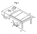
Fig. 1 is a perspective view of the use of a device according to the present invention, where parts of a decorative tablecloth are removed to make it easier to see the heating mat; -
Fig. 2 is a block diagram of the present invention; -
Fig. 3 is a schematic view of the position of the induction elements in the heating mat; -
Fig. 4 illustrates an induction element; and -
Figs. 5A and 5B illustrate various weak points in the heating mat. - We now refer to
fig. 1 , where an embodiment of the invention is illustrated. A device for maintaining temperature in food and drink comprises aheating mat 10 connected to anenergy converter 11 by means of anelectrical cable 12. The energy converter in turn is connected to a power supply 46 (illustrated infig. 2 ), such as the power supply grid, by means of an electricalpower supply cable 13. - In
fig. 1 theheating mat 10 is placed on a table 14, on which are placed, for example,containers 15 of food and drink that is ready to serve. Adecorative tablecloth 16 is preferably placed over theheating mat 10 as decoration. - Furthermore, the energy converter is mounted on a
transport unit 17 to facilitate the transport thereof. - The
transport unit 17 is preferably of a size that enables it to be concealed below the table 14 and thedecorative tablecloth 16. - The
heating mat 10 will now be described with reference tofig. 3 . Here theheating mat 10 comprises athin plate 20 of a non-metallic material wherein a plurality ofheating elements 22 are mounted. Thethin plate 20 is preferably a flexible, heat-resistant material, which enables theplate 20 to be rolled up, bent or folded for storage. - The material in the
thin plate 20 may be plastic, silicon, rubber, composite materials or the like. A material that has been found suitable to date is Elastolan™, which is relatively malleable, soft and workable, while being temperature-constant within the temperature limits required for the present embodiment. In this context temperature-constant means that the material can withstand a continuous temperature of approximately 100°C and a maximum transitory temperature of approximately 130°C. - In the bottom of the
heating mat 10 there is preferably placed alayer 19 of ferrite in powder form, which will have no effect on the softness and ductility of theheating mat 10. The object of this is to limit and/or obstruct the magnetic radiation in the direction down towards the table 14, since screws and other metal objects in the table could be heated by the radiation. By this means a magnetic field is obtained which is substantially directed upwards from theheating mat 10, as illustrated infig 1 . - In the present embodiment the
heating elements 22 are distributed in such a manner that there are fourheating elements 22 in the width of theheating mat 10. This is illustrated infig. 3 . It will, of course, be possible to vary the number, spacing and relative positions of theheating elements 22 according to the desired area of application. - In
fig. 4 a heating element of this kind is illustrated, comprising a preferably spiral-shapedelectrical conductor 30 with asupply conductor 32. Thesupply conductor 32 is connected to supply conductors toother heating elements 22 and/or connected directly to theenergy converter 11 via thecable 12. Thecable 12 can therefore comprise a number ofelectrical conductors 30. Thus eachheating element 22 is an induction coil that generates a time-variable magnetic field by means of the electric current from theenergy converter 11. Theheating element 12 may further comprise support means (not shown) for maintaining the shape of theelectrical conductor 30 during production, since the latter in itself does not have sufficient rigidity. The support means may comprise adhesive or the like, or may be made of the same material as theplate 20. - The
heating mat 10 may be produced by casting or smelting in theheating elements 22 and the ferrite layer into theplate 20, or by gluing togetherseveral plates 20 withheating elements 22 and the ferrite layer placed in layers between them. - The heating mat preferably also comprises a plurality of sensors 18 (
fig. 2 ). These will be described below. - Furthermore
weak points figs. 5A and 5B ). Theweak points plate 20, and help to simplify folding of theheating mat 10 for storage. Theweak points fig. 5A ) or substantially U-shaped grooves (fig. 5B ) in theplate 20, but they may also be perforated with through-going cut-outs at intervals. - The
energy converter 11 will now be described with reference tofig. 2 . Here theenergy converter 11 comprises acontrol unit 42 which receives signals from an operatingunit 40 and thesensors 18 in theheating mat 10. Thecontrol unit 42 is further connected to anenergy conversion unit 44. - The operating
unit 40 comprises one or more switches and one or more temperature indicators that give a reference signal for temperature to thecontrol unit 42. Theheating mat 10 can thereby be divided into several temperature zones, where switching on and off and temperature control can be individually set for each zone. - In the preferred embodiment the
sensors 18 are temperature sensors that are mounted close to one ormore heating elements 22. Thesensors 18 record the surface temperature in theheating mat 10, which thecontrol unit 42 then uses to control the power to theheating elements 22. For example, a check can be made as to whether food is placed on an adjacent heating element that needs continuous heating, and this is done by switching on the induction heating for a brief moment. A check is then made as to whether the surface temperature of the cloth/underlay increases. If the temperature increases, this is interpreted as being an induction container with food placed on the heating element. If the temperature does not rise, the induction heating is switched off again. - The
control unit 42 comprises a suitable microprocessor and electronic storage devices or possibly programmable logic for receiving and transmitting signals as described above. - The
energy conversion unit 44 receives electrical energy from thepower supply 46 and supplies converted energy for induction heating to theheating element 22 in theheating mat 10 based on the control signals from the operatingunit 40 and thesensors 18. Theenergy conversion unit 44 comprises an induction resonator that converts the energy from the mains voltage to a voltage with a frequency which, for example, varies in the range 20 - 40 kHz and which generates a suitable magnetic field capable of maintaining the temperature in food and drink. - The embodiment described above is intended as an example of the present invention, and it will, of course be possible for a person skilled in the art to vary it within the scope of the patent claims. For
small heating mats 10 it will probably be possible to equip theenergy converter 11 with a handle, and it will need no separate transport unit, but possibly can be attached to the table 14. It will, of course, also be possible to omit the sensors and only have the ability to switch off and on one or more zones on theheating mat 10.
Claims (7)
- A device for maintaining temperature in food and drink by means of the induction principle,
characterised in that it comprises a thin heating mat (10) which may be rolled, bent or folded to reduce its plan area for storage, on which induction containers and other types of containers for food and drink can be placed, and an energy converter (11) for connection to a power supply (46) and to the heating mat (10), where the energy converter (11) converts the energy from the power supply to induction energy and where the heating mat (10) comprises:- a plate (20) of a heat-resistant, non-metallic material,- at least one heating element (22) for generating a varying magnetic field by means of the induction energy from the energy converter (11). - A device according to patent claim 1,
characterised in that the heating element (22) is cast into, smelted into, glued to or in some other way mounted in the plate (20). - A device according to patent claim 1 or 2,
characterised in that the heat-resistant material in the plate (20) can withstand a continuous temperature of approximately 100°C and a maximum, transitory temperature of approximately 130°C. - A device according to one of the above patent claims,
characterised in that the material in the plate (20) is flexible to enable the plate (20) to be rolled up or bent for storage. - A device according to one of claims 1 to 4,
characterised in that weak points (24a, 24b) are provided in the plate (20) in order to simplify folding up the heating mat (10) for storage. - A device according to one of the above patent claims,
characterised in that the heating element (22) comprises an induction coil in the form of an electrical conductor (30) and a supply conductor (32) connected to the energy converter (11). - A device according to one of the above patent claims,
characterised in that the heating mat (10) further comprises a layer (19) of ferrite or another metallic material, arranged under the heating elements (22).
Priority Applications (1)
| Application Number | Priority Date | Filing Date | Title |
|---|---|---|---|
| PL05764297T PL1773163T3 (en) | 2004-06-17 | 2005-06-16 | A device for maintaining temperature in food and drink |
Applications Claiming Priority (2)
| Application Number | Priority Date | Filing Date | Title |
|---|---|---|---|
| NO20042538A NO320968B1 (en) | 2004-06-17 | 2004-06-17 | Device for maintaining temperature in food and drink |
| PCT/NO2005/000213 WO2005122854A1 (en) | 2004-06-17 | 2005-06-16 | A device for maintaining temperature in food and drink |
Publications (2)
| Publication Number | Publication Date |
|---|---|
| EP1773163A1 EP1773163A1 (en) | 2007-04-18 |
| EP1773163B1 true EP1773163B1 (en) | 2008-03-26 |
Family
ID=35005939
Family Applications (1)
| Application Number | Title | Priority Date | Filing Date |
|---|---|---|---|
| EP05764297A Not-in-force EP1773163B1 (en) | 2004-06-17 | 2005-06-16 | A device for maintaining temperature in food and drink |
Country Status (13)
| Country | Link |
|---|---|
| US (1) | US7750273B2 (en) |
| EP (1) | EP1773163B1 (en) |
| JP (1) | JP4929169B2 (en) |
| CN (1) | CN100522028C (en) |
| AT (1) | ATE390068T1 (en) |
| DE (1) | DE602005005680T2 (en) |
| DK (1) | DK1773163T3 (en) |
| ES (1) | ES2307193T3 (en) |
| HK (1) | HK1105342A1 (en) |
| NO (1) | NO320968B1 (en) |
| PL (1) | PL1773163T3 (en) |
| PT (1) | PT1773163E (en) |
| WO (1) | WO2005122854A1 (en) |
Families Citing this family (20)
| Publication number | Priority date | Publication date | Assignee | Title |
|---|---|---|---|---|
| CA2728738C (en) * | 2008-06-24 | 2015-02-10 | Aktiebolaget Electrolux | Cooking table |
| JP5313334B2 (en) * | 2009-03-13 | 2013-10-09 | パナソニック株式会社 | Induction heating cooker and kitchen device |
| FR3003741A1 (en) * | 2013-03-29 | 2014-10-03 | Jean-Francois Maurice Louiche | REFRIGERATED TABLE PLATE. |
| SG2013057377A (en) * | 2013-07-26 | 2015-02-27 | Tai Wah Distributors Pte Ltd | Hair appliances heating mat |
| KR101589701B1 (en) | 2015-08-13 | 2016-01-28 | (주)피스월드 | cooking vessel supporting apparatus for smart under range |
| US11596264B2 (en) | 2015-12-16 | 2023-03-07 | David A. Gober | Radiant furniture |
| US11751693B2 (en) | 2015-12-16 | 2023-09-12 | David A. Gober | Radiant furniture |
| US10463148B2 (en) * | 2015-12-16 | 2019-11-05 | David A. Gober | Radiant furniture |
| US11363890B2 (en) | 2015-12-16 | 2022-06-21 | David A. Gober | Radiant furniture |
| KR102500523B1 (en) * | 2016-03-28 | 2023-02-15 | 엘지전자 주식회사 | Induction heating device |
| US11665790B2 (en) * | 2016-12-22 | 2023-05-30 | Whirlpool Corporation | Induction burner element having a plurality of single piece frames |
| JP6717217B2 (en) * | 2017-01-27 | 2020-07-01 | 京セラドキュメントソリューションズ株式会社 | Electrophotographic photoreceptor, process cartridge and image forming apparatus |
| US10548398B2 (en) * | 2017-05-18 | 2020-02-04 | Edible Education Llc | Wheeled kitchen apparatus with collapsible work surface |
| CN109309981B (en) * | 2017-07-28 | 2021-12-28 | 佛山市顺德区美的电热电器制造有限公司 | Coil panel and electromagnetic oven with same |
| WO2019178675A1 (en) * | 2018-03-17 | 2019-09-26 | Monteiro Nelson Walter | Induction heated hand tool container |
| DE102018130735A1 (en) * | 2018-12-03 | 2020-06-04 | BOL-Lifestyle GmbH | Device for the electrical control of the temperature of containers on plate-like supports |
| DE102019119964B4 (en) * | 2019-07-24 | 2022-09-08 | Surteco Gmbh | Heated surface covering, heated structure, method and covering panel |
| DE102020000851A1 (en) | 2020-02-11 | 2021-08-12 | Jochen Stephan | Warming device for food |
| USD1000205S1 (en) | 2021-03-05 | 2023-10-03 | Tramontina Teec S.A. | Cooktop or portion thereof |
| USD1000206S1 (en) | 2021-03-05 | 2023-10-03 | Tramontina Teec S.A. | Cooktop or portion thereof |
Family Cites Families (12)
| Publication number | Priority date | Publication date | Assignee | Title |
|---|---|---|---|---|
| US3740513A (en) | 1971-09-23 | 1973-06-19 | Environment One Corp | Improved consumer oriented combined counter and cooking unit using induction heating |
| US3786222A (en) | 1972-04-19 | 1974-01-15 | Gen Electric | Metallic foil induction cooking |
| US4038518A (en) * | 1976-05-24 | 1977-07-26 | Morton Richard F | Dining table combined with food warming apparatus |
| GB1592034A (en) | 1978-02-21 | 1981-07-01 | Neddide A M | Tables with heating elements |
| JPS63224177A (en) * | 1987-03-11 | 1988-09-19 | シャープ株式会社 | Electromagnetic cooker |
| ZA872635B (en) | 1987-05-11 | 1987-12-30 | Norman William Crook | Table place mats |
| US5155316A (en) * | 1990-12-24 | 1992-10-13 | Chiu Sou Kuein | Heat-conducting mat for absorbing microwave and electromagnetic wave energy |
| FR2737638B1 (en) | 1995-08-03 | 1997-10-03 | Bourgeois Prod Coop | INDUCTION TRAY HEATING DEVICE |
| US5954984A (en) | 1996-07-31 | 1999-09-21 | Thermal Solutions Inc. | Heat retentive food servingware with temperature self-regulating phase change core |
| FR2756448B1 (en) * | 1996-11-26 | 2003-06-13 | Simeray Jannick Jacques | DEVICE FOR HEATING A CULINARY CONTAINER |
| JPH10233321A (en) * | 1997-02-19 | 1998-09-02 | Jiemitsukusu Kk | Sheet coil for high-frequency induction heating |
| JPH11102778A (en) * | 1997-09-29 | 1999-04-13 | Matsushita Electric Ind Co Ltd | Induction heating cooking device |
-
2004
- 2004-06-17 NO NO20042538A patent/NO320968B1/en not_active IP Right Cessation
-
2005
- 2005-06-16 PL PL05764297T patent/PL1773163T3/en unknown
- 2005-06-16 US US11/570,073 patent/US7750273B2/en not_active Expired - Fee Related
- 2005-06-16 ES ES05764297T patent/ES2307193T3/en active Active
- 2005-06-16 DK DK05764297T patent/DK1773163T3/en active
- 2005-06-16 CN CNB2005800198257A patent/CN100522028C/en not_active Expired - Fee Related
- 2005-06-16 PT PT05764297T patent/PT1773163E/en unknown
- 2005-06-16 JP JP2007516413A patent/JP4929169B2/en not_active Expired - Fee Related
- 2005-06-16 DE DE602005005680T patent/DE602005005680T2/en active Active
- 2005-06-16 EP EP05764297A patent/EP1773163B1/en not_active Not-in-force
- 2005-06-16 WO PCT/NO2005/000213 patent/WO2005122854A1/en active Application Filing
- 2005-06-16 AT AT05764297T patent/ATE390068T1/en active
-
2007
- 2007-09-28 HK HK07110571A patent/HK1105342A1/en not_active IP Right Cessation
Also Published As
| Publication number | Publication date |
|---|---|
| ES2307193T3 (en) | 2008-11-16 |
| DE602005005680D1 (en) | 2008-05-08 |
| PT1773163E (en) | 2008-07-04 |
| CN1997305A (en) | 2007-07-11 |
| JP4929169B2 (en) | 2012-05-09 |
| NO20042538D0 (en) | 2004-06-17 |
| DK1773163T3 (en) | 2008-07-28 |
| HK1105342A1 (en) | 2008-02-15 |
| WO2005122854A1 (en) | 2005-12-29 |
| EP1773163A1 (en) | 2007-04-18 |
| ATE390068T1 (en) | 2008-04-15 |
| NO320968B1 (en) | 2006-02-20 |
| PL1773163T3 (en) | 2008-09-30 |
| CN100522028C (en) | 2009-08-05 |
| JP2008503050A (en) | 2008-01-31 |
| US7750273B2 (en) | 2010-07-06 |
| US20080000895A1 (en) | 2008-01-03 |
| DE602005005680T2 (en) | 2009-04-09 |
Similar Documents
| Publication | Publication Date | Title |
|---|---|---|
| EP1773163B1 (en) | A device for maintaining temperature in food and drink | |
| JP6162719B2 (en) | Electromagnetic induction cooking system | |
| US4776386A (en) | Apparatus for cooling, storing and reheating food using induction heating | |
| EP3820248B1 (en) | Table-type cooking device | |
| WO2015095885A1 (en) | Vertical tortilla cooking device | |
| US7703384B2 (en) | Height-adjustable food transfer platform | |
| US20170164777A1 (en) | Induction cooktop | |
| AU2011251905A1 (en) | Portable device for induction cooking | |
| US6831256B2 (en) | Super-thin restaurant griddle | |
| JPS5833676B2 (en) | Denki Energy Denso Sochi | |
| CN203280256U (en) | Multifunctional heater and pot and disc | |
| JP5002179B2 (en) | System kitchen | |
| JP2007265904A (en) | Built in kitchen unit and dielectric heating unit | |
| JP6564281B2 (en) | Temperature control system | |
| CN201328691Y (en) | Combination pot with sub-control structure | |
| JP2012187243A (en) | Food warming dish and power feeding device | |
| JP2013137938A (en) | Induction heating cooker | |
| CN207561724U (en) | Split cooking apparatus | |
| CN101444393B (en) | Combined pot with branch control structure | |
| US20190306930A1 (en) | Induction heating and cooking | |
| EP3295841B1 (en) | Cooking device | |
| CN216453960U (en) | Electromagnetic heating structure of dining table | |
| CN203234557U (en) | Three-purpose pot | |
| JP2002313549A (en) | Electromagnetic cooking method and device, and container used for the same | |
| US6140611A (en) | Process for supplying heat to an object and container for keeping dishes hot and reheating dishes |
Legal Events
| Date | Code | Title | Description |
|---|---|---|---|
| PUAI | Public reference made under article 153(3) epc to a published international application that has entered the european phase |
Free format text: ORIGINAL CODE: 0009012 |
|
| 17P | Request for examination filed |
Effective date: 20070117 |
|
| AK | Designated contracting states |
Kind code of ref document: A1 Designated state(s): AT BE BG CH CY CZ DE DK EE ES FI FR GB GR HU IE IS IT LI LT LU MC NL PL PT RO SE SI SK TR |
|
| 17Q | First examination report despatched |
Effective date: 20070503 |
|
| DAX | Request for extension of the european patent (deleted) | ||
| GRAP | Despatch of communication of intention to grant a patent |
Free format text: ORIGINAL CODE: EPIDOSNIGR1 |
|
| REG | Reference to a national code |
Ref country code: HK Ref legal event code: DE Ref document number: 1105342 Country of ref document: HK |
|
| GRAS | Grant fee paid |
Free format text: ORIGINAL CODE: EPIDOSNIGR3 |
|
| GRAA | (expected) grant |
Free format text: ORIGINAL CODE: 0009210 |
|
| AK | Designated contracting states |
Kind code of ref document: B1 Designated state(s): AT BE BG CH CY CZ DE DK EE ES FI FR GB GR HU IE IS IT LI LT LU MC NL PL PT RO SE SI SK TR |
|
| REG | Reference to a national code |
Ref country code: GB Ref legal event code: FG4D |
|
| REG | Reference to a national code |
Ref country code: CH Ref legal event code: EP Ref country code: IE Ref legal event code: FG4D |
|
| REF | Corresponds to: |
Ref document number: 602005005680 Country of ref document: DE Date of ref document: 20080508 Kind code of ref document: P |
|
| REG | Reference to a national code |
Ref country code: HK Ref legal event code: GR Ref document number: 1105342 Country of ref document: HK |
|
| REG | Reference to a national code |
Ref country code: PT Ref legal event code: SC4A Free format text: AVAILABILITY OF NATIONAL TRANSLATION Effective date: 20080623 |
|
| REG | Reference to a national code |
Ref country code: SE Ref legal event code: TRGR |
|
| REG | Reference to a national code |
Ref country code: DK Ref legal event code: T3 |
|
| REG | Reference to a national code |
Ref country code: CH Ref legal event code: NV Representative=s name: PATENTANWAELTE SCHAAD, BALASS, MENZL & PARTNER AG |
|
| PG25 | Lapsed in a contracting state [announced via postgrant information from national office to epo] |
Ref country code: SI Free format text: LAPSE BECAUSE OF FAILURE TO SUBMIT A TRANSLATION OF THE DESCRIPTION OR TO PAY THE FEE WITHIN THE PRESCRIBED TIME-LIMIT Effective date: 20080326 |
|
| REG | Reference to a national code |
Ref country code: PL Ref legal event code: T3 |
|
| PG25 | Lapsed in a contracting state [announced via postgrant information from national office to epo] |
Ref country code: CZ Free format text: LAPSE BECAUSE OF FAILURE TO SUBMIT A TRANSLATION OF THE DESCRIPTION OR TO PAY THE FEE WITHIN THE PRESCRIBED TIME-LIMIT Effective date: 20080326 Ref country code: SK Free format text: LAPSE BECAUSE OF FAILURE TO SUBMIT A TRANSLATION OF THE DESCRIPTION OR TO PAY THE FEE WITHIN THE PRESCRIBED TIME-LIMIT Effective date: 20080326 |
|
| REG | Reference to a national code |
Ref country code: ES Ref legal event code: FG2A Ref document number: 2307193 Country of ref document: ES Kind code of ref document: T3 |
|
| PG25 | Lapsed in a contracting state [announced via postgrant information from national office to epo] |
Ref country code: RO Free format text: LAPSE BECAUSE OF FAILURE TO SUBMIT A TRANSLATION OF THE DESCRIPTION OR TO PAY THE FEE WITHIN THE PRESCRIBED TIME-LIMIT Effective date: 20080326 |
|
| PG25 | Lapsed in a contracting state [announced via postgrant information from national office to epo] |
Ref country code: IS Free format text: LAPSE BECAUSE OF FAILURE TO SUBMIT A TRANSLATION OF THE DESCRIPTION OR TO PAY THE FEE WITHIN THE PRESCRIBED TIME-LIMIT Effective date: 20080726 |
|
| ET | Fr: translation filed | ||
| PG25 | Lapsed in a contracting state [announced via postgrant information from national office to epo] |
Ref country code: LT Free format text: LAPSE BECAUSE OF FAILURE TO SUBMIT A TRANSLATION OF THE DESCRIPTION OR TO PAY THE FEE WITHIN THE PRESCRIBED TIME-LIMIT Effective date: 20080326 Ref country code: MC Free format text: LAPSE BECAUSE OF NON-PAYMENT OF DUE FEES Effective date: 20080630 |
|
| PLBE | No opposition filed within time limit |
Free format text: ORIGINAL CODE: 0009261 |
|
| STAA | Information on the status of an ep patent application or granted ep patent |
Free format text: STATUS: NO OPPOSITION FILED WITHIN TIME LIMIT |
|
| 26N | No opposition filed |
Effective date: 20081230 |
|
| PG25 | Lapsed in a contracting state [announced via postgrant information from national office to epo] |
Ref country code: EE Free format text: LAPSE BECAUSE OF FAILURE TO SUBMIT A TRANSLATION OF THE DESCRIPTION OR TO PAY THE FEE WITHIN THE PRESCRIBED TIME-LIMIT Effective date: 20080326 Ref country code: BG Free format text: LAPSE BECAUSE OF FAILURE TO SUBMIT A TRANSLATION OF THE DESCRIPTION OR TO PAY THE FEE WITHIN THE PRESCRIBED TIME-LIMIT Effective date: 20080626 |
|
| PG25 | Lapsed in a contracting state [announced via postgrant information from national office to epo] |
Ref country code: CY Free format text: LAPSE BECAUSE OF FAILURE TO SUBMIT A TRANSLATION OF THE DESCRIPTION OR TO PAY THE FEE WITHIN THE PRESCRIBED TIME-LIMIT Effective date: 20080326 |
|
| PG25 | Lapsed in a contracting state [announced via postgrant information from national office to epo] |
Ref country code: LU Free format text: LAPSE BECAUSE OF NON-PAYMENT OF DUE FEES Effective date: 20080616 Ref country code: HU Free format text: LAPSE BECAUSE OF FAILURE TO SUBMIT A TRANSLATION OF THE DESCRIPTION OR TO PAY THE FEE WITHIN THE PRESCRIBED TIME-LIMIT Effective date: 20080927 |
|
| PG25 | Lapsed in a contracting state [announced via postgrant information from national office to epo] |
Ref country code: TR Free format text: LAPSE BECAUSE OF FAILURE TO SUBMIT A TRANSLATION OF THE DESCRIPTION OR TO PAY THE FEE WITHIN THE PRESCRIBED TIME-LIMIT Effective date: 20080326 |
|
| PG25 | Lapsed in a contracting state [announced via postgrant information from national office to epo] |
Ref country code: GR Free format text: LAPSE BECAUSE OF FAILURE TO SUBMIT A TRANSLATION OF THE DESCRIPTION OR TO PAY THE FEE WITHIN THE PRESCRIBED TIME-LIMIT Effective date: 20080627 |
|
| PGFP | Annual fee paid to national office [announced via postgrant information from national office to epo] |
Ref country code: CH Payment date: 20120622 Year of fee payment: 8 Ref country code: DK Payment date: 20120620 Year of fee payment: 8 |
|
| PGFP | Annual fee paid to national office [announced via postgrant information from national office to epo] |
Ref country code: FI Payment date: 20120613 Year of fee payment: 8 |
|
| PGFP | Annual fee paid to national office [announced via postgrant information from national office to epo] |
Ref country code: BE Payment date: 20120621 Year of fee payment: 8 |
|
| PGFP | Annual fee paid to national office [announced via postgrant information from national office to epo] |
Ref country code: AT Payment date: 20120613 Year of fee payment: 8 |
|
| PGFP | Annual fee paid to national office [announced via postgrant information from national office to epo] |
Ref country code: PT Payment date: 20130621 Year of fee payment: 9 |
|
| BERE | Be: lapsed |
Owner name: HERVING, STALE Effective date: 20130630 |
|
| REG | Reference to a national code |
Ref country code: CH Ref legal event code: PL |
|
| REG | Reference to a national code |
Ref country code: DK Ref legal event code: EBP Effective date: 20130630 |
|
| REG | Reference to a national code |
Ref country code: AT Ref legal event code: MM01 Ref document number: 390068 Country of ref document: AT Kind code of ref document: T Effective date: 20130616 |
|
| PG25 | Lapsed in a contracting state [announced via postgrant information from national office to epo] |
Ref country code: FI Free format text: LAPSE BECAUSE OF NON-PAYMENT OF DUE FEES Effective date: 20130616 |
|
| PG25 | Lapsed in a contracting state [announced via postgrant information from national office to epo] |
Ref country code: BE Free format text: LAPSE BECAUSE OF NON-PAYMENT OF DUE FEES Effective date: 20130630 |
|
| PG25 | Lapsed in a contracting state [announced via postgrant information from national office to epo] |
Ref country code: LI Free format text: LAPSE BECAUSE OF NON-PAYMENT OF DUE FEES Effective date: 20130630 Ref country code: CH Free format text: LAPSE BECAUSE OF NON-PAYMENT OF DUE FEES Effective date: 20130630 |
|
| PG25 | Lapsed in a contracting state [announced via postgrant information from national office to epo] |
Ref country code: AT Free format text: LAPSE BECAUSE OF NON-PAYMENT OF DUE FEES Effective date: 20130616 |
|
| PG25 | Lapsed in a contracting state [announced via postgrant information from national office to epo] |
Ref country code: DK Free format text: LAPSE BECAUSE OF NON-PAYMENT OF DUE FEES Effective date: 20130630 |
|
| REG | Reference to a national code |
Ref country code: PT Ref legal event code: MM4A Free format text: LAPSE DUE TO NON-PAYMENT OF FEES Effective date: 20141216 |
|
| PG25 | Lapsed in a contracting state [announced via postgrant information from national office to epo] |
Ref country code: PT Free format text: LAPSE BECAUSE OF NON-PAYMENT OF DUE FEES Effective date: 20141216 |
|
| PGFP | Annual fee paid to national office [announced via postgrant information from national office to epo] |
Ref country code: PL Payment date: 20150611 Year of fee payment: 11 Ref country code: NL Payment date: 20150618 Year of fee payment: 11 Ref country code: IE Payment date: 20150619 Year of fee payment: 11 |
|
| REG | Reference to a national code |
Ref country code: FR Ref legal event code: PLFP Year of fee payment: 12 |
|
| REG | Reference to a national code |
Ref country code: NL Ref legal event code: MM Effective date: 20160701 |
|
| REG | Reference to a national code |
Ref country code: IE Ref legal event code: MM4A |
|
| PG25 | Lapsed in a contracting state [announced via postgrant information from national office to epo] |
Ref country code: IE Free format text: LAPSE BECAUSE OF NON-PAYMENT OF DUE FEES Effective date: 20160616 Ref country code: NL Free format text: LAPSE BECAUSE OF NON-PAYMENT OF DUE FEES Effective date: 20160701 |
|
| REG | Reference to a national code |
Ref country code: FR Ref legal event code: PLFP Year of fee payment: 13 |
|
| PG25 | Lapsed in a contracting state [announced via postgrant information from national office to epo] |
Ref country code: PL Free format text: LAPSE BECAUSE OF NON-PAYMENT OF DUE FEES Effective date: 20160616 |
|
| REG | Reference to a national code |
Ref country code: FR Ref legal event code: PLFP Year of fee payment: 14 |
|
| PGFP | Annual fee paid to national office [announced via postgrant information from national office to epo] |
Ref country code: DE Payment date: 20180625 Year of fee payment: 14 |
|
| PGFP | Annual fee paid to national office [announced via postgrant information from national office to epo] |
Ref country code: FR Payment date: 20180620 Year of fee payment: 14 |
|
| PGFP | Annual fee paid to national office [announced via postgrant information from national office to epo] |
Ref country code: SE Payment date: 20180620 Year of fee payment: 14 |
|
| PGFP | Annual fee paid to national office [announced via postgrant information from national office to epo] |
Ref country code: GB Payment date: 20180620 Year of fee payment: 14 Ref country code: ES Payment date: 20180724 Year of fee payment: 14 Ref country code: IT Payment date: 20180627 Year of fee payment: 14 |
|
| REG | Reference to a national code |
Ref country code: DE Ref legal event code: R119 Ref document number: 602005005680 Country of ref document: DE |
|
| REG | Reference to a national code |
Ref country code: SE Ref legal event code: EUG |
|
| PG25 | Lapsed in a contracting state [announced via postgrant information from national office to epo] |
Ref country code: SE Free format text: LAPSE BECAUSE OF NON-PAYMENT OF DUE FEES Effective date: 20190617 |
|
| GBPC | Gb: european patent ceased through non-payment of renewal fee |
Effective date: 20190616 |
|
| PG25 | Lapsed in a contracting state [announced via postgrant information from national office to epo] |
Ref country code: IT Free format text: LAPSE BECAUSE OF NON-PAYMENT OF DUE FEES Effective date: 20190616 Ref country code: DE Free format text: LAPSE BECAUSE OF NON-PAYMENT OF DUE FEES Effective date: 20200101 Ref country code: GB Free format text: LAPSE BECAUSE OF NON-PAYMENT OF DUE FEES Effective date: 20190616 |
|
| PG25 | Lapsed in a contracting state [announced via postgrant information from national office to epo] |
Ref country code: FR Free format text: LAPSE BECAUSE OF NON-PAYMENT OF DUE FEES Effective date: 20190630 |
|
| REG | Reference to a national code |
Ref country code: ES Ref legal event code: FD2A Effective date: 20201028 |
|
| PG25 | Lapsed in a contracting state [announced via postgrant information from national office to epo] |
Ref country code: ES Free format text: LAPSE BECAUSE OF NON-PAYMENT OF DUE FEES Effective date: 20190617 |