JP4929169B2 - Device for maintaining food and beverage temperatures - Google Patents
Device for maintaining food and beverage temperatures Download PDFInfo
- Publication number
- JP4929169B2 JP4929169B2 JP2007516413A JP2007516413A JP4929169B2 JP 4929169 B2 JP4929169 B2 JP 4929169B2 JP 2007516413 A JP2007516413 A JP 2007516413A JP 2007516413 A JP2007516413 A JP 2007516413A JP 4929169 B2 JP4929169 B2 JP 4929169B2
- Authority
- JP
- Japan
- Prior art keywords
- plate
- mat
- temperature
- energy
- energy converter
- Prior art date
- Legal status (The legal status is an assumption and is not a legal conclusion. Google has not performed a legal analysis and makes no representation as to the accuracy of the status listed.)
- Expired - Fee Related
Links
Images


Classifications
-
- A—HUMAN NECESSITIES
- A47—FURNITURE; DOMESTIC ARTICLES OR APPLIANCES; COFFEE MILLS; SPICE MILLS; SUCTION CLEANERS IN GENERAL
- A47J—KITCHEN EQUIPMENT; COFFEE MILLS; SPICE MILLS; APPARATUS FOR MAKING BEVERAGES
- A47J36/00—Parts, details or accessories of cooking-vessels
- A47J36/24—Warming devices
- A47J36/2483—Warming devices with electrical heating means
-
- H—ELECTRICITY
- H05—ELECTRIC TECHNIQUES NOT OTHERWISE PROVIDED FOR
- H05B—ELECTRIC HEATING; ELECTRIC LIGHT SOURCES NOT OTHERWISE PROVIDED FOR; CIRCUIT ARRANGEMENTS FOR ELECTRIC LIGHT SOURCES, IN GENERAL
- H05B6/00—Heating by electric, magnetic or electromagnetic fields
- H05B6/02—Induction heating
- H05B6/10—Induction heating apparatus, other than furnaces, for specific applications
- H05B6/12—Cooking devices
-
- A—HUMAN NECESSITIES
- A47—FURNITURE; DOMESTIC ARTICLES OR APPLIANCES; COFFEE MILLS; SPICE MILLS; SUCTION CLEANERS IN GENERAL
- A47B—TABLES; DESKS; OFFICE FURNITURE; CABINETS; DRAWERS; GENERAL DETAILS OF FURNITURE
- A47B2200/00—General construction of tables or desks
- A47B2200/0001—Tops
- A47B2200/0009—Plate and dish warming plates embedded in table top
Abstract
Description
本発明は、誘導原理による食品および/または飲料の温度を維持するためのデバイスに関する。この文脈において、「温度を維持する」との概念は、食品および/または飲料を、短期間または長期間ほぼ同じ温度に保つことを意味する。結果的に、温度における漸進的な上昇または下降もまた、この概念に包含される。 The present invention relates to a device for maintaining the temperature of food and / or beverage according to the induction principle. In this context, the concept of “maintaining temperature” means keeping food and / or beverages at about the same temperature for short or long periods. Consequently, gradual increases or decreases in temperature are also encompassed by this concept.
(従来技術)
今日の食品および飲料の加温は、通常は、ホットプレートにおける電気的エネルギーの熱への変換により実施され、次いでその熱が熱導体によってその食品を収容している容器に伝達される。誘導によって食品を加温する場合は、この電気的エネルギーは、その食品容器に対する種々の磁場によって伝達される。この容器は、種々の磁場におけるエネルギーを熱へ変換するように設計される。
(Conventional technology)
Today's food and beverage warming is usually performed by the conversion of electrical energy into heat on a hot plate, which is then transferred by a heat conductor to the container containing the food. When heating food by induction, this electrical energy is transmitted by various magnetic fields on the food container. This container is designed to convert energy in various magnetic fields into heat.
誘導によって加温するためのデバイスは、電力網からの電気的エネルギーを高周波数の電気的エネルギー(以後、誘導エネルギーと呼ぶ)に変換するためのエネルギー変換器を必要とする。この変換機は、1つ以上の誘導コイルによって上述の種々の磁場を生成する。上述のように熱を生成し得る特別な容器(例えば、ポットおよび鍋などの用具)もまた、食品のために必要とされる。そのような容器は、以後、誘導容器と呼ぶ。 Devices for heating by induction require an energy converter to convert electrical energy from the power grid into high frequency electrical energy (hereinafter referred to as inductive energy). This transducer generates the various magnetic fields described above by means of one or more induction coils. Special containers that can generate heat as described above (eg utensils such as pots and pans) are also needed for food. Such containers are hereinafter referred to as induction containers.
給仕場所(例えば、ホテル、レストラン、カフェなど)は、食品が用意されてから長期間、食品および/または飲料における温度を維持することが必要である。このことはまた、一個人の家庭にも適用可能であり得る。食品および飲料において温度を維持するための公知のデバイスは、テーブル上に配置されるかまたはテーブルに組み込まれた特別なユニットから構成され、金属のホットプレートの下に配置される加温要素を備える。この熱は、熱導体によって、金属ホットプレートから食品容器へ伝達される。これらのデバイスは、多数の不利を有する。例えば、この加温要素は重く、組み込み型の加温要素を備えるテーブルは、しばしば、必要に応じて車輪を外さなければならない分離型テーブルである。 Serving locations (eg, hotels, restaurants, cafes, etc.) need to maintain temperature in food and / or beverages for an extended period of time after food is prepared. This may also be applicable to an individual home. Known devices for maintaining temperature in foods and beverages comprise a special unit that is arranged on a table or built into a table and comprises a heating element that is arranged under a metal hot plate . This heat is transferred from the metal hot plate to the food container by a heat conductor. These devices have a number of disadvantages. For example, this warming element is heavy, and tables with built-in warming elements are often separable tables where the wheels must be removed as needed.
従来技術の不利は、そのようなデバイスが多大な空間を占め、かつ重いということである。このことは、そのデバイスが使用されないときにも保管空間を占め、そして多くの作業が、それを動かし、戻すのに伴って生じることを意味する。多くの給仕場所は、朝食および昼食を給仕するときにそのようなテーブルを使用し、一方で夕食が給仕されるときにはそのテーブルは移動させられる。 The disadvantage of the prior art is that such devices take up a lot of space and are heavy. This means that when the device is not in use it takes up storage space and a lot of work occurs as it is moved and returned. Many serving locations use such tables when serving breakfast and lunch, while they are moved when dinner is served.
同時に、金属のホットプレートは、テーブルの全表面を覆い、それによってそのテーブル上に置かれた全てのものが加温されるようにする。従って、冷えた皿は、他の型のテーブル上に置かれなければならない。 At the same time, the metal hot plate covers the entire surface of the table so that everything placed on the table is warmed. Therefore, chilled dishes must be placed on other types of tables.
特許文献1において、食品を有する給仕トレーの誘導加温のためのデバイスが開示されている。このデバイスは、多数の給仕トレーが積み重ね得られるスタンドを備え、そしてその給仕トレー間に、磁性誘導によって加温され得るユニットが取り付けられる。スタンド全体がデバイス内に転がり込み、種々の磁場によって、給仕トレーと結果的に食品とが加温される。このデバイスはまた、どの誘導コイルが活性化されるべきであるのかを制御可能にするために、給仕トレーの存在または非存在を検出するための多数のセンサーを備える。
特許文献2は、テーブルトップに挿入された実質的にU字型の部材を備える、誘導加温のためのデバイスを図示する。 U.S. Patent No. 6,099,036 illustrates a device for induction warming comprising a substantially U-shaped member inserted into a table top.
さらに、特許文献3は、特別な厚さのアルミニウム箔が鋳型内に押し付けられている誘導加温のためのデバイスを図示する。食品はそのアルミニウム箔内に置かれ、次いで誘導によって加温される。この食品が熱い場合は、その食品はアルミニウム箔から食され、このアルミニウム箔は次いで廃棄される。それによって、鍋などの清掃および洗浄ならびに保管に対する必要性を低減させる。 In addition, US Pat. No. 6,057,051 illustrates a device for induction heating in which a special thickness of aluminum foil is pressed into a mold. The food is placed in the aluminum foil and then heated by induction. If the food is hot, the food is eaten from the aluminum foil which is then discarded. Thereby reducing the need for cleaning and washing and storage of pans and the like.
従って、相対的に小さい空間しか占めず、取り出しおよび洗浄するのが容易である、誘導による熱の維持のためのデバイスを製造することが望ましい。従来のテーブルが、そのデバイスと一緒に使用されることもまた、望ましい。 Therefore, it is desirable to produce a device for maintaining heat by induction that occupies a relatively small space and is easy to remove and clean. It is also desirable that a conventional table be used with the device.
さらに、全ての型の食品をデバイス上に置くことができ、温かめられるべき食品のみが温かいままであることが望ましい。
本発明は、誘導原理によって、食品および飲料において温度を維持するためのデバイスに関する。このデバイスは、加温マットであって、この加温マット上に食品および飲料用の誘導容器および他の型の容器が配置され得る、加温マット、ならびに電源および該加温マットへの接続のためのエネルギー変換器を備え、ここでこのエネルギー変換器は、その電源からのエネルギーを誘導エネルギーに変換し、その加温マットは、以下:
−耐熱性の非金属材料製のプレート、
−そのエネルギー変換器からの誘導エネルギーによって種々の磁場を生成するための、少なくとも1つの加温要素、を備える。
The present invention relates to a device for maintaining temperature in foods and beverages by the induction principle. The device is a warming mat on which a food and beverage induction container and other types of containers can be placed, as well as a power source and connection to the warming mat For energy conversion, where this energy converter converts the energy from its power source into inductive energy, and its heating mat is the following:
- heat-resistant non-metallic materials made of Plate,
-Comprising at least one heating element for generating various magnetic fields by means of inductive energy from the energy converter.
好ましい実施形態において、加温要素は、プレートに、鋳造されるか、溶融されるか、接着されるか、または他の方法で取り付けられる。 In a preferred embodiment, heating element, the Plate, or be cast, either melted, is attach with adhesive to be or otherwise.
好ましい実施形態において、プレートにおける耐熱性材料は、約100℃の連続的温度および約130℃の最大の一過性温度に耐え得る。 In a preferred embodiment, heat-resistant materials in Plate can withstand continuously the temperature and maximum transient temperatures of about 130 ° C. to about 100 ° C..
好ましい実施形態において、プレートにおける材料は可撓性であり、そのプレートが保管のために丸められるか、曲げられるか、または折り畳まれることを可能にする。 In a preferred embodiment, the material in the Plate is flexible, or Plate of that is rounded for storage, to be either bent or folded.
好ましい実施形態において、保管のために加温マットを折り畳むのを容易にするために、弱い部位がそのプレートに提供される。 In a preferred embodiment, in order to facilitate the folding of the heating mat for storage, it is provided to Plate weak sites pixels.
好ましい実施形態において、加温要素は、電導体の形態の誘導コイルおよびエネルギー変換器に接続された供給導体を備える。 In a preferred embodiment, the warming element comprises an induction coil in the form of an electrical conductor and a supply conductor connected to the energy converter.
好ましい実施形態において、加温マットは、加温要素の下に配置された、フェライトまたは別の金属の層をさらに備える。 In a preferred embodiment, the heating mat further comprises a layer of ferrite or another metal disposed under the heating element.
本発明は、ここで、本発明の好ましい実施形態の例によって説明され、ここで参照が添付の図面に対してなされる。 The invention will now be described by way of examples of preferred embodiments of the invention, wherein reference is now made to the accompanying drawings.
(詳細な説明)
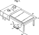
ここで図1を参照すると、本発明の実施形態が図示されている。食品および飲料における温度を維持するためのデバイスは、電気ケーブル12によってエネルギー変換器11に接続される加温マット10を備える。次いでこのエネルギー変換器は、電源(例えば、電力源網)46(図2において図示される)に、電源供給ケーブル13によって接続される。
(Detailed explanation)
Referring now to FIG. 1, an embodiment of the present invention is illustrated. The device for maintaining the temperature in food and beverage comprises a
図1において、加温マット10は、テーブル14上に置かれ、この上に、例えば給仕される準備の整った食品および飲料の容器15が置かれる。装飾的なテーブルクロス16が、好ましくは、装飾として加温マット10を覆う。さらに、エネルギー変換器は、運搬ユニット17上に取り付けられ、その運搬を容易にする。
In FIG. 1, the
運搬ユニット17は、好ましくは、それがテーブル14および装飾的テーブルクロス16の下に隠されることを可能にするサイズである。
The
ここで加温マット10を、図3を参照して説明する。ここで、加温マット10は、非金属製の薄いプレート20を備え、この上に複数の加温要素22が取り付けられる。薄いプレート20は、好ましくは、可撓性の耐熱性材料であり、プレート20が、保管のために丸められるか、曲げられるか、または折り畳まれることを可能にする。
Here, the
薄いプレート20における材料は、プラスチック、シリコーン、ゴム、複合材料などであり得る。これまでに適していることが見出されている材料は、ElastolanTMである。これは本実施形態のために必要とされる温度制限内で温度定常性(temperature constant)でありながら、比較的可鍛性、柔軟および機能的である。この文脈において、温度定常性とは、この材料が、約100℃の連続的温度および約130℃の最大の一過性温度に耐え得ることを意味する。
The material in the
加温マット10の底に、好ましくは粉末形態のフェライトの層19が置かれる。これは、加温マット10の柔軟性および延性について影響を有さない。この目的は、テーブル14の下方向への磁気放射を制限および/または妨害することである。なぜなら、テーブル内のねじおよび他の金属物体が、放射によって加熱され得るからである。このため、図1に示されるように、加温マット10から実質的に上方向の磁場が得られる。
On the bottom of the
本実施形態において、加温要素22は、加温マット10の幅に4つの加温要素22が存在するような様式で分布される。これは図3に図示されている。当然、用途の所望される領域に従って、加温要素22の数、間隔、および相対位置は変動することが可能である。
In the present embodiment, the
図4において、この種類の加温要素が図示され、供給導体32を備える好ましいらせん形の電導体30を備える。この供給導体32は、他の加温要素22に対する供給導体に接続され、そして/またはケーブル12を介してエネルギー変換器11に直接接続される。それゆえ、ケーブル12は、多数の電導体30を供え得る。従って、各加温要素22が、エネルギー変換器11からの電流によって時間変化の磁場を生成する誘導コイルである。加温要素12は、製造の間に電導体30の形状を維持するための支持手段(示さず)をさらに備え得る。なぜなら、電導体30は、それ自体では十分な剛性を有さないからである。この支持手段は、接着剤などを含んでもよいし、プレート20と同じ材料から作製されてもよい。
In FIG. 4, a warming element of this kind is illustrated, comprising a preferred
加温マット10は、加温要素22およびフェライト層をプレート20内に鋳造するかまたは溶融して製造されてもよいし、複数のプレート20を加温要素22と一緒に接着し、フェライト層をそれらの間の層に置いて製造されてもよい。
The
加温マットは、好ましくは、複数のセンサー18(図2)もまた備える。これらは、以下に説明される。 The warming mat preferably also includes a plurality of sensors 18 (FIG. 2). These are described below.
さらに、弱い点24a、24bが、好ましくはプレート20に提供される(図5Aおよび図5Bに図示される)。弱い点24a、24bは、プレート20に平行に、そして/または交差して周期的に配置され、保管のための加温マット10の折り畳むことを容易にするのを助ける。弱い点24a、24bは、プレート20において実質的にV字型の断面(図5A)であってもよいし、実質的にU字型の溝(図5B)であってもよいが、それらはまた、間隔を置いて貫通する切り口(through−going cut−out)で穴を開けられてもよい。
In addition,
ここでエネルギー変換器11を、図2を参照して説明する。ここで、エネルギー変換器11は、操作ユニット40および加温マット10におけるセンサー18からのシグナルを受容する制御ユニット42を備える。制御ユニット42は、エネルギー変換ユニット44にさらに接続される。
The
操作ユニット40は、1つ以上のスイッチ、および制御ユニット42に温度についての参照シグナルを与える1つ以上の温度表示を備える。それにより加温マット10は、複数の温度ゾーンに分割され得、ここで、スイッチオンおよびスイッチオフ、ならびに温度制御が、各ゾーンに対して個別に設定され得る。
The operating
好ましい実施形態において、センサー18は、1つ以上の加温要素22の近くに取り付けられる温度センサーである。センサー18は、加温マット10の表面温度を記録し、次いでこれを制御ユニット42が加温要素22の出力を制御するのに使用する。例えば、チェックが、食品が、連続的加温を必要とする隣接した加温要素上に置かれたか否かに関してなされ得る。これは、誘導加温を一瞬スイッチオンにすることによってなされる。次いで、クロス/下敷きの表面温度が上昇しているか否かに関して、チェックがなされる。温度が上昇した場合は、このことは、食品を含む誘導容器が加温要素上に置かれたと解釈される。温度が上がらない場合は、誘導加温は再度スイッチオフにされる。
In a preferred embodiment,
制御ユニット42は、上記のシグナルを受容および伝達するための、適したマイクロプロセッサおよび電気的保管デバイス、またはおそらくプログラム可能な論理を備える。
The
エネルギー変換ユニット44は、電源46からの電気的エネルギーを受容し、そして誘導加熱のための変換されたエネルギーを、操作ユニット40およびセンサー18からの制御シグナルに基づいて、加温マット10における加温要素22に供給する。エネルギー変換ユニット44は、誘導共鳴装置を備える。この誘導共鳴装置は、主電圧からのエネルギーを、例えば20kHz〜40kHzを変動する周波数を有する電圧に変換し、食品および飲料において温度を維持し得る適切な磁場を生成する。
The
上記の実施形態は、本発明の例示として意図され、特許請求の範囲の範囲内でその実施形態を改変することは、当業者には当然可能なことである。小さな加温マット10については、ハンドルを有するエネルギー変換器11を備えることはおそらく可能であり、そして分離型の運搬ユニットは不要であり、おそらくテーブル14に取り付けられ得る。当然、センサーを除き、加温マット10上の1つ以上のゾーンのスイッチをオフおよびオンにする能力を有するだけであることも、可能である。
The above embodiments are intended as examples of the present invention, and it is obvious that those skilled in the art can modify the embodiments within the scope of the claims. For a
Claims (6)
保管のために平面の面積を減少させるために、丸められるか、曲げられるか、または折り畳まれ得る、薄い加温マット(10)であって、該加温マット上に食品および飲料用の誘導容器および他の型の容器が配置され得る、加温マット(10)、ならびに
電源(46)および該加温マット(10)への接続のためのエネルギー変換器(11)、
を備え、ここで該エネルギー変換器(11)は、該電源からのエネルギーを誘導エネルギーに変換し、該エネルギー変換器(11)は、操作ユニット(40)からのシグナルを受容する制御ユニット(42)を備え、
該加温マット(10)は、以下:
−耐熱性の非金属材料製のプレート(20)であって、該プレート(20)における該材料が可撓性であり、該プレート(20)が保管のために丸められ、曲げられ、または折り畳まれることを可能にする、プレート(20)、
−該エネルギー変換器(11)からの誘導エネルギーによって種々の磁場を生成するための、誘導コイルを含む少なくとも1つの加温要素(22)、
−該少なくとも1つの加温要素(22)の近くに取り付けられた少なくとも1つの温度センサー(18)であって、該温度センサー(18)は、該加温マット(10)における表面温度を記録するためのものであり、次いで該表面温度を、該制御ユニット(42)が該少なくとも1つの加温要素(22)への出力を制御するために使用する、温度センサー(18)
を備える、デバイス。A device for maintaining the temperature of food and beverages according to the induction principle, the device comprising:
A thin warming mat (10) that can be rolled, bent or folded to reduce the area of the plane for storage, on which the guiding container for food and beverages And an energy converter (11) for connection to a power source (46) and to the warming mat (10)
Wherein the energy converter (11) converts energy from the power source into inductive energy, the energy converter (11) receiving a signal from the operating unit (40). )
The warming mat (10) is:
A plate (20) made of a heat-resistant non-metallic material , wherein the material in the plate (20) is flexible, the plate (20) being rolled, bent or folded for storage The plate (20) ,
At least one heating element (22) including an induction coil for generating various magnetic fields by means of inductive energy from the energy converter (11);
At least one temperature sensor (18) mounted in the vicinity of the at least one heating element (22), the temperature sensor (18) recording the surface temperature at the heating mat (10); A temperature sensor (18), wherein the surface temperature is then used by the control unit (42) to control the output to the at least one heating element (22)
A device comprising:
Applications Claiming Priority (3)
| Application Number | Priority Date | Filing Date | Title |
|---|---|---|---|
| NO20042538A NO320968B1 (en) | 2004-06-17 | 2004-06-17 | Device for maintaining temperature in food and drink |
| NO20042538 | 2004-06-17 | ||
| PCT/NO2005/000213 WO2005122854A1 (en) | 2004-06-17 | 2005-06-16 | A device for maintaining temperature in food and drink |
Publications (3)
| Publication Number | Publication Date |
|---|---|
| JP2008503050A JP2008503050A (en) | 2008-01-31 |
| JP2008503050A5 JP2008503050A5 (en) | 2008-07-31 |
| JP4929169B2 true JP4929169B2 (en) | 2012-05-09 |
Family
ID=35005939
Family Applications (1)
| Application Number | Title | Priority Date | Filing Date |
|---|---|---|---|
| JP2007516413A Expired - Fee Related JP4929169B2 (en) | 2004-06-17 | 2005-06-16 | Device for maintaining food and beverage temperatures |
Country Status (13)
| Country | Link |
|---|---|
| US (1) | US7750273B2 (en) |
| EP (1) | EP1773163B1 (en) |
| JP (1) | JP4929169B2 (en) |
| CN (1) | CN100522028C (en) |
| AT (1) | ATE390068T1 (en) |
| DE (1) | DE602005005680T2 (en) |
| DK (1) | DK1773163T3 (en) |
| ES (1) | ES2307193T3 (en) |
| HK (1) | HK1105342A1 (en) |
| NO (1) | NO320968B1 (en) |
| PL (1) | PL1773163T3 (en) |
| PT (1) | PT1773163E (en) |
| WO (1) | WO2005122854A1 (en) |
Families Citing this family (20)
| Publication number | Priority date | Publication date | Assignee | Title |
|---|---|---|---|---|
| CA2728738C (en) * | 2008-06-24 | 2015-02-10 | Aktiebolaget Electrolux | Cooking table |
| JP5313334B2 (en) * | 2009-03-13 | 2013-10-09 | パナソニック株式会社 | Induction heating cooker and kitchen device |
| FR3003741A1 (en) * | 2013-03-29 | 2014-10-03 | Jean-Francois Maurice Louiche | REFRIGERATED TABLE PLATE. |
| SG2013057377A (en) * | 2013-07-26 | 2015-02-27 | Tai Wah Distributors Pte Ltd | Hair appliances heating mat |
| KR101589701B1 (en) | 2015-08-13 | 2016-01-28 | (주)피스월드 | cooking vessel supporting apparatus for smart under range |
| US11596264B2 (en) | 2015-12-16 | 2023-03-07 | David A. Gober | Radiant furniture |
| US11751693B2 (en) | 2015-12-16 | 2023-09-12 | David A. Gober | Radiant furniture |
| US10463148B2 (en) * | 2015-12-16 | 2019-11-05 | David A. Gober | Radiant furniture |
| US11363890B2 (en) | 2015-12-16 | 2022-06-21 | David A. Gober | Radiant furniture |
| KR102500523B1 (en) * | 2016-03-28 | 2023-02-15 | 엘지전자 주식회사 | Induction heating device |
| US11665790B2 (en) * | 2016-12-22 | 2023-05-30 | Whirlpool Corporation | Induction burner element having a plurality of single piece frames |
| JP6717217B2 (en) * | 2017-01-27 | 2020-07-01 | 京セラドキュメントソリューションズ株式会社 | Electrophotographic photoreceptor, process cartridge and image forming apparatus |
| US10548398B2 (en) * | 2017-05-18 | 2020-02-04 | Edible Education Llc | Wheeled kitchen apparatus with collapsible work surface |
| CN109309981B (en) * | 2017-07-28 | 2021-12-28 | 佛山市顺德区美的电热电器制造有限公司 | Coil panel and electromagnetic oven with same |
| WO2019178675A1 (en) * | 2018-03-17 | 2019-09-26 | Monteiro Nelson Walter | Induction heated hand tool container |
| DE102018130735A1 (en) * | 2018-12-03 | 2020-06-04 | BOL-Lifestyle GmbH | Device for the electrical control of the temperature of containers on plate-like supports |
| DE102019119964B4 (en) * | 2019-07-24 | 2022-09-08 | Surteco Gmbh | Heated surface covering, heated structure, method and covering panel |
| DE102020000851A1 (en) | 2020-02-11 | 2021-08-12 | Jochen Stephan | Warming device for food |
| USD1000205S1 (en) | 2021-03-05 | 2023-10-03 | Tramontina Teec S.A. | Cooktop or portion thereof |
| USD1000206S1 (en) | 2021-03-05 | 2023-10-03 | Tramontina Teec S.A. | Cooktop or portion thereof |
Citations (4)
| Publication number | Priority date | Publication date | Assignee | Title |
|---|---|---|---|---|
| JPS63224177A (en) * | 1987-03-11 | 1988-09-19 | シャープ株式会社 | Electromagnetic cooker |
| JPH10233321A (en) * | 1997-02-19 | 1998-09-02 | Jiemitsukusu Kk | Sheet coil for high-frequency induction heating |
| JPH11102778A (en) * | 1997-09-29 | 1999-04-13 | Matsushita Electric Ind Co Ltd | Induction heating cooking device |
| JP2001504637A (en) * | 1996-11-26 | 2001-04-03 | シムレイ,ジャニック | Cooking vessel heating device |
Family Cites Families (8)
| Publication number | Priority date | Publication date | Assignee | Title |
|---|---|---|---|---|
| US3740513A (en) | 1971-09-23 | 1973-06-19 | Environment One Corp | Improved consumer oriented combined counter and cooking unit using induction heating |
| US3786222A (en) | 1972-04-19 | 1974-01-15 | Gen Electric | Metallic foil induction cooking |
| US4038518A (en) * | 1976-05-24 | 1977-07-26 | Morton Richard F | Dining table combined with food warming apparatus |
| GB1592034A (en) | 1978-02-21 | 1981-07-01 | Neddide A M | Tables with heating elements |
| ZA872635B (en) | 1987-05-11 | 1987-12-30 | Norman William Crook | Table place mats |
| US5155316A (en) * | 1990-12-24 | 1992-10-13 | Chiu Sou Kuein | Heat-conducting mat for absorbing microwave and electromagnetic wave energy |
| FR2737638B1 (en) | 1995-08-03 | 1997-10-03 | Bourgeois Prod Coop | INDUCTION TRAY HEATING DEVICE |
| US5954984A (en) | 1996-07-31 | 1999-09-21 | Thermal Solutions Inc. | Heat retentive food servingware with temperature self-regulating phase change core |
-
2004
- 2004-06-17 NO NO20042538A patent/NO320968B1/en not_active IP Right Cessation
-
2005
- 2005-06-16 PL PL05764297T patent/PL1773163T3/en unknown
- 2005-06-16 US US11/570,073 patent/US7750273B2/en not_active Expired - Fee Related
- 2005-06-16 ES ES05764297T patent/ES2307193T3/en active Active
- 2005-06-16 DK DK05764297T patent/DK1773163T3/en active
- 2005-06-16 CN CNB2005800198257A patent/CN100522028C/en not_active Expired - Fee Related
- 2005-06-16 PT PT05764297T patent/PT1773163E/en unknown
- 2005-06-16 JP JP2007516413A patent/JP4929169B2/en not_active Expired - Fee Related
- 2005-06-16 DE DE602005005680T patent/DE602005005680T2/en active Active
- 2005-06-16 EP EP05764297A patent/EP1773163B1/en not_active Not-in-force
- 2005-06-16 WO PCT/NO2005/000213 patent/WO2005122854A1/en active Application Filing
- 2005-06-16 AT AT05764297T patent/ATE390068T1/en active
-
2007
- 2007-09-28 HK HK07110571A patent/HK1105342A1/en not_active IP Right Cessation
Patent Citations (4)
| Publication number | Priority date | Publication date | Assignee | Title |
|---|---|---|---|---|
| JPS63224177A (en) * | 1987-03-11 | 1988-09-19 | シャープ株式会社 | Electromagnetic cooker |
| JP2001504637A (en) * | 1996-11-26 | 2001-04-03 | シムレイ,ジャニック | Cooking vessel heating device |
| JPH10233321A (en) * | 1997-02-19 | 1998-09-02 | Jiemitsukusu Kk | Sheet coil for high-frequency induction heating |
| JPH11102778A (en) * | 1997-09-29 | 1999-04-13 | Matsushita Electric Ind Co Ltd | Induction heating cooking device |
Also Published As
| Publication number | Publication date |
|---|---|
| ES2307193T3 (en) | 2008-11-16 |
| DE602005005680D1 (en) | 2008-05-08 |
| PT1773163E (en) | 2008-07-04 |
| CN1997305A (en) | 2007-07-11 |
| NO20042538D0 (en) | 2004-06-17 |
| EP1773163B1 (en) | 2008-03-26 |
| DK1773163T3 (en) | 2008-07-28 |
| HK1105342A1 (en) | 2008-02-15 |
| WO2005122854A1 (en) | 2005-12-29 |
| EP1773163A1 (en) | 2007-04-18 |
| ATE390068T1 (en) | 2008-04-15 |
| NO320968B1 (en) | 2006-02-20 |
| PL1773163T3 (en) | 2008-09-30 |
| CN100522028C (en) | 2009-08-05 |
| JP2008503050A (en) | 2008-01-31 |
| US7750273B2 (en) | 2010-07-06 |
| US20080000895A1 (en) | 2008-01-03 |
| DE602005005680T2 (en) | 2009-04-09 |
Similar Documents
| Publication | Publication Date | Title |
|---|---|---|
| JP4929169B2 (en) | Device for maintaining food and beverage temperatures | |
| JP6162719B2 (en) | Electromagnetic induction cooking system | |
| US6849830B2 (en) | Apparatus and method of rapidly and evenly heating a packaged food product | |
| EP1466503A1 (en) | Food cooking or warming apparatus with self-regulating inductor | |
| KR101489942B1 (en) | Induction cooking equipment for individual use at kitchen table | |
| JP5964629B2 (en) | Electromagnetic induction heating aid and electromagnetic induction heating pan set | |
| US9596722B2 (en) | Induction cooking apparatus and method of use | |
| US11950726B2 (en) | Drinkware container with active temperature control | |
| JP5404917B2 (en) | Induction heating tableware to keep dishes warm | |
| DE60112818D1 (en) | COOKER | |
| JP6564281B2 (en) | Temperature control system | |
| JP2012187243A (en) | Food warming dish and power feeding device | |
| JP3668102B2 (en) | Chariot | |
| CN207561724U (en) | Split cooking apparatus | |
| JP3122701U (en) | Insulation for electromagnetic induction cooker | |
| EP2226568A2 (en) | Cooktop accessory forming interface with a wok type heating plate | |
| US20190306930A1 (en) | Induction heating and cooking | |
| JP6960568B2 (en) | Induction heating cooker | |
| JP5846326B1 (en) | Cooking equipment | |
| JP2001052848A (en) | Electromagnetic induction heating device | |
| JP2008123804A5 (en) | ||
| JP2000300354A (en) | Meal service wagon | |
| EP0873669B1 (en) | A cooker | |
| JP2000229040A (en) | Meal supplying waiting car | |
| JP2015226615A (en) | Hot plate |
Legal Events
| Date | Code | Title | Description |
|---|---|---|---|
| A521 | Request for written amendment filed |
Free format text: JAPANESE INTERMEDIATE CODE: A523 Effective date: 20080613 |
|
| A621 | Written request for application examination |
Free format text: JAPANESE INTERMEDIATE CODE: A621 Effective date: 20080613 |
|
| A131 | Notification of reasons for refusal |
Free format text: JAPANESE INTERMEDIATE CODE: A131 Effective date: 20110512 |
|
| A601 | Written request for extension of time |
Free format text: JAPANESE INTERMEDIATE CODE: A601 Effective date: 20110725 |
|
| A602 | Written permission of extension of time |
Free format text: JAPANESE INTERMEDIATE CODE: A602 Effective date: 20110801 |
|
| A521 | Request for written amendment filed |
Free format text: JAPANESE INTERMEDIATE CODE: A523 Effective date: 20110912 |
|
| TRDD | Decision of grant or rejection written | ||
| A01 | Written decision to grant a patent or to grant a registration (utility model) |
Free format text: JAPANESE INTERMEDIATE CODE: A01 Effective date: 20120125 |
|
| A01 | Written decision to grant a patent or to grant a registration (utility model) |
Free format text: JAPANESE INTERMEDIATE CODE: A01 |
|
| A61 | First payment of annual fees (during grant procedure) |
Free format text: JAPANESE INTERMEDIATE CODE: A61 Effective date: 20120213 |
|
| FPAY | Renewal fee payment (event date is renewal date of database) |
Free format text: PAYMENT UNTIL: 20150217 Year of fee payment: 3 |
|
| R150 | Certificate of patent or registration of utility model |
Ref document number: 4929169 Country of ref document: JP Free format text: JAPANESE INTERMEDIATE CODE: R150 Free format text: JAPANESE INTERMEDIATE CODE: R150 |
|
| R250 | Receipt of annual fees |
Free format text: JAPANESE INTERMEDIATE CODE: R250 |
|
| R250 | Receipt of annual fees |
Free format text: JAPANESE INTERMEDIATE CODE: R250 |
|
| R250 | Receipt of annual fees |
Free format text: JAPANESE INTERMEDIATE CODE: R250 |
|
| R250 | Receipt of annual fees |
Free format text: JAPANESE INTERMEDIATE CODE: R250 |
|
| LAPS | Cancellation because of no payment of annual fees |