EP1769727A2 - Elektronisches Endoskopsystem - Google Patents
Elektronisches Endoskopsystem Download PDFInfo
- Publication number
- EP1769727A2 EP1769727A2 EP06020132A EP06020132A EP1769727A2 EP 1769727 A2 EP1769727 A2 EP 1769727A2 EP 06020132 A EP06020132 A EP 06020132A EP 06020132 A EP06020132 A EP 06020132A EP 1769727 A2 EP1769727 A2 EP 1769727A2
- Authority
- EP
- European Patent Office
- Prior art keywords
- synchronizing signal
- electronic endoscope
- signals
- signal
- synchronization codes
- Prior art date
- Legal status (The legal status is an assumption and is not a legal conclusion. Google has not performed a legal analysis and makes no representation as to the accuracy of the status listed.)
- Withdrawn
Links
Images

Classifications
-
- A—HUMAN NECESSITIES
- A61—MEDICAL OR VETERINARY SCIENCE; HYGIENE
- A61B—DIAGNOSIS; SURGERY; IDENTIFICATION
- A61B1/00—Instruments for performing medical examinations of the interior of cavities or tubes of the body by visual or photographical inspection, e.g. endoscopes; Illuminating arrangements therefor
- A61B1/04—Instruments for performing medical examinations of the interior of cavities or tubes of the body by visual or photographical inspection, e.g. endoscopes; Illuminating arrangements therefor combined with photographic or television appliances
- A61B1/045—Control thereof
-
- A—HUMAN NECESSITIES
- A61—MEDICAL OR VETERINARY SCIENCE; HYGIENE
- A61B—DIAGNOSIS; SURGERY; IDENTIFICATION
- A61B1/00—Instruments for performing medical examinations of the interior of cavities or tubes of the body by visual or photographical inspection, e.g. endoscopes; Illuminating arrangements therefor
- A61B1/04—Instruments for performing medical examinations of the interior of cavities or tubes of the body by visual or photographical inspection, e.g. endoscopes; Illuminating arrangements therefor combined with photographic or television appliances
- A61B1/05—Instruments for performing medical examinations of the interior of cavities or tubes of the body by visual or photographical inspection, e.g. endoscopes; Illuminating arrangements therefor combined with photographic or television appliances characterised by the image sensor, e.g. camera, being in the distal end portion
-
- H—ELECTRICITY
- H04—ELECTRIC COMMUNICATION TECHNIQUE
- H04N—PICTORIAL COMMUNICATION, e.g. TELEVISION
- H04N23/00—Cameras or camera modules comprising electronic image sensors; Control thereof
- H04N23/60—Control of cameras or camera modules
- H04N23/66—Remote control of cameras or camera parts, e.g. by remote control devices
-
- H—ELECTRICITY
- H04—ELECTRIC COMMUNICATION TECHNIQUE
- H04N—PICTORIAL COMMUNICATION, e.g. TELEVISION
- H04N23/00—Cameras or camera modules comprising electronic image sensors; Control thereof
- H04N23/50—Constructional details
- H04N23/555—Constructional details for picking-up images in sites, inaccessible due to their dimensions or hazardous conditions, e.g. endoscopes or borescopes
Definitions
- the present invention relates to an electronic endoscope system constituted of an electronic endoscope and a processor between which signals are transmitted and received via radio waves.
- an imaging sensor such as a CCD is incorporated in a front end portion of an insertion section for being inserted into a body cavity.
- Image signals obtained by the CCD are subject to signal processing in a processor to display an image of the body cavity, that is, an endoscopic image, on a monitor.
- the conventional electronic endoscope and the processor are connected through a signal cable.
- a wireless electronic endoscope system is devised which transmits and receives the signals via radio waves without using the signal cable to improve operability of the electronic endoscope (see United States Patent No. 4,633,304 and Japanese Patent Laid-Open Publication No. 2001-046334 ).
- a modulating section for modulating the signals and a transmitter for transmitting the signals via the radio waves are provided in the electronic endoscope, and a receiver for receiving the radio waves and a demodulating section for demodulating the radio waves into the original signals are provided in the processor.
- the conventional electronic endoscope with the signal cable requires approximately 4kV of dielectric strength voltage between a patient circuit in the electronic endoscope and a secondary circuit in the processor.
- dielectric strength voltage is unnecessary in the wireless electronic endoscope system since the signal cable is not used between the electronic endoscope and the processor.
- the processor since the processor receives image signals obtained by the electronic endoscope to display the endoscopic image on the monitor, synchronization between the electronic endoscope and the processor is needed.
- a main object of the present invention is to provide an electronic endoscope system in which both image signals and synchronizing signals can be transmitted in a single frequency band and the synchronizing signals can be surely detected.
- an electronic endoscope system of the present invention is constituted of an electronic endoscope and a processor.
- the electronic endoscope includes an imaging sensor, an A/D converter, a synchronizing signal encoder, a modulating section and a transmitter.
- the imaging sensor obtains an image of an observation area of a subject and outputs analog image signals.
- the A/D converter converts the analog image signals into digital image signals.
- the synchronizing signal encoder encodes a vertical synchronizing signal and a horizontal synchronizing signal into synchronization codes representing ON/OFF states thereof expressed by several maximums and minimums of signal levels for representing the digital image signals, and uses a maximum and a minimum signal levels except the signal levels representing the synchronization codes to express the digital image signals which would normally be represented by the signal levels representing the synchronization codes, while the image signals whose levels are not in the signal levels representing the synchronization codes are not subject to change.
- the modulating section applies a digital quadrature modulation to the synchronization codes and the image signals to generate RF signals.
- the transmitter transmits the RF signals to the processor as a radio wave.
- the processor includes a receiver, a demodulating section, a synchronizing signal decoder and an image signal processing section.
- the receiver receives the RF signals transmitted from the transmitter.
- the demodulating section demodulates the RF signals into the image signals by digital quadrature detection.
- the synchronizing signal decoder decodes the vertical synchronizing signal and the horizontal synchronizing signal based on the synchronization codes.
- the image signal processing section generates an endoscopic image from the image signals.
- the electronic endoscope since the electronic endoscope includes the synchronizing signal encoder which encodes a vertical synchronizing signal and a horizontal synchronizing signal into synchronization codes representing ON/OFF states thereof expressed by several maximums and minimums of signal levels for representing the digital image signals, and uses a maximum and a minimum signal levels except the signal levels representing the synchronization codes to express the digital image signals which would normally be represented by the signal levels representing the synchronization codes, while the image signals whose levels are not in the signal levels representing the synchronization codes are not subject to change, and the processor includes the synchronizing signal decoder which decodes the vertical synchronizing signal and the horizontal synchronizing signal based on the synchronization codes, both the image signals and the synchronizing signals can be transmitted in a single frequency band and the synchronizing signals can be surely detected.
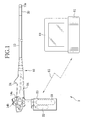
- an electronic endoscope system 2 is constituted of an electronic endoscope 10 and a processor 11. Signals are transmitted between the electronic endoscope 10 and the processor 11 via radio waves 12.
- the electronic endoscope 10 is provided with an insertion section 13 inserted into a body cavity, and an operating section 14 connected to a base end portion of the insertion section 13.
- a front end section 13a of the insertion section 13 incorporates an objective lens 15 for taking image light of an observation area in the body cavity, a CCD 16 (for example, a number of pixels is 1280x960 and a frame rate is 30 frames/second) which is an image sensor for capturing the image of the observation area in the body cavity, and an illumination lens 17 and an LED light source (hereinafter, an LED) 18 for illuminating inside the body cavity (see Fig. 2).
- the image of the body cavity taken by the CCD 16 is displayed as an endoscopic image on amonitor 19 connected to the processor 11.
- Behind the front end section 13a there is a flexible section 20 formed of plural joint pieces.
- a wire extending through the insertion section 13 is pushed and pulled by operating an angle knob 14a provided in the operating section 14 to bend the flexible section 20 in the up, down, right and left directions.
- the front end section 13a can be directed toward a desired direction inside the body cavity.
- a cartridge 23 incorporating a water tank 21 and an air cylinder 22 is attached to a bottom portion of the operating section 14 in a removable manner. Water is stored in the water tank 21 and air is stored in the air cylinder 22.
- a water/air supply button 14b in the operating section 14 is operated, the water in the water tank 21 and the air in the air cylinder 22 are respectively supplied through a water pipe and an air pipe and ejected from a washing nozzle (not shown) formed in the front end section 13a to the objective lens 15. Thereby, dirt adhered to a surface of the objective lens 15 is removed and the air is supplied to the body cavity.
- a numeral 24 is a forceps opening into which a treatment tool is inserted.
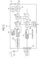
- a CPU 30 controls overall operation of the electronic endoscope 10.
- the CPU 30 is connected to a ROM 31 which stores various programs and data for controlling the operation of the electronic endoscope 10.
- the CPU 30 reads necessary program and/or data from the ROM 31 to control the operation of the electronic endoscope 10.
- a timing generator (TG) 32 is connected to the CPU 30.
- the TG 32 is connected to the CCD 16, an AFE 34 and a parallel/serial converter (P/S) 35 which are described later, and sends timing signals (clock pulses) to these components.
- the CCD 16, the AFE 34 and the P/S 35 operate based on the timing signals from the TG 32.
- a drive section 33 is connected to the LED 18.
- the drive section 33 drives the LED 18 under control of the CPU 30.
- the light emitted from the LED 18 illuminates the observation area in the body cavity through the illumination lens 17.
- the CCD 16 converts the image light of the observation area focused through the objective lens 15 onto its image capture surface, and outputs the image signals corresponding to light intensity on each pixel to anAFE 34.
- the AFE 34 performs correlated double sampling, amplification and A/D conversion to the image signals to convert the analog image signals into digital image signals (10 bit, see FIG.3).
- VSYNC vertical synchronizing signals
- HSYNC horizontal synchronizing signals
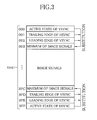
- the P/S 35 encodes the VSYNC and the HSYNC into synchronization codes expressed by signal levels of 10 bit for representing the image signals.
- the synchronization codes "3FF” (in hexadecimal notation, the maximum level of 10 bit) represents an active state of the HSYNC
- "3FE” represents a leading edge of the HSYNC
- "3FD” represents a trailing edge of the VSYNC
- "002” represents a leading edge of the VSYNC
- "001" represents a trailing edge of the HSYNC
- "000” the minimum level of 10 bit
- the P/S 35 uses the signal levels "3FC” and "003", which are the maximum and minimum signal levels except the signal levels representing the synchronization codes, to express the image signals which would normally be represented by 3FD to 3FF and 000 to 002.
- the P/S 35 converts parallel data of the digital image signals and the synchronization codes, into serial data.
- a modulating section 36 applies a digital quadrature modulation such as Quadrature Phase Shift Keying (QPSK) to the serial data output from the P/S 35, to generate RF signals.
- a transmitter 37 transmits the RF signals to the processor 11 as the radio wave 12 through an antenna 38.
- QPSK Quadrature Phase Shift Keying
- a battery 40 is connected to a connector 39. Power of the battery 40 is supplied to each section of the electronic endoscope 10 through a power supply section 41 controlled by the CPU 30. Behind the operating section 14, a battery chamber (not shown) is provided for accommodating the battery 40, and the connector 39 is disposed inside the battery chamber.
- a CPU 50 controls overall operation of the processor 11.
- the CPU 50 is connected to a ROM 51 in which various programs and data for controlling the operation of the processor 11 are stored.
- the CPU 50 reads the necessary program and data from the ROM 51 to control the operation of the processor 11.
- An antenna 52 receives the radio wave 12 from the electronic endoscope 10.
- a receiver 53 amplifies the radio wave 12, that is, the RF signals received through the antenna 52.
- a demodulating section 54 demodulates the RF signals into the image signals and the synchronization codes by, for instance, the digital quadrature detection.
- a synchronizing signal decoder 55 decodes the HSYNC and the VSYNC based on the synchronization codes demodulated by the demodulating section 54, under the control of the CPU 50.
- An image signal processing section 56 generates digital video signals from the image signals.
- a video signal processing section 57 performs image processing such as mask generation and addition of character information to the digital video signals.
- a buffer 58 temporarily stores the digital video signals which will be displayed on the monitor 19 as the endoscopic image.
- the insertion section 13 is inserted into the body cavity while the LED 18 is turned on to illuminate the body cavity.
- the endoscopic image obtained by the CCD 16 is observed on the monitor 19.
- the image light of the observation area in the body cavity entered through the objective lens 15 is focused on the image capture surface of the CCD 16, and thereby the image signals are output from the CCD 16 to the AFE 34.
- the correlated double sampling, the amplification and the A/D conversion are performed to the image signals to convert the analog image signals into the digital image signal.
- the digital image signals output from the AFE 34 are converted into the serial data by the P/S 35.
- the P/S 35 applies the serial conversion to the VSYNC and the HSYNC for the image signal, which are produced based on the timing signals from the TG 32.
- the P/S 35 encodes the VSYNC and the HSYNC into the synchronization codes expressed by the signal levels of 10 bit for representing the image signals.
- the synchronization codes "3FF” represents the active state of the HSYNC, "3FE” represents the leading edge of the HSYNC, “3FD” represents the trailing edge of the VSYNC, “002” represents the leading edge of the VSYNC, "001” represents the trailing edge of the HSYNC, and "000” represents the active state of the VSYNC.
- the P/S 35 uses the signal levels "3FC” and "003", which are the maximum and minimum signal levels except the signal levels representing the synchronization codes, to express the image signals which would normally be represented by 3FD to 3FF and 000 to 002.
- the image signals in signal levels of 003 to 3FC, which are not for representing the synchronization codes, are subject to the serial conversion directly. Accordingly, a frequency band dedicated for the synchronizing signals is not required, and both the synchronizing signals and the image signals can be transmitted as the radio wave 12 in a single frequency band.
- the digital quadrature modulation is performed to the serial data output from the P/S 35 to generate the RF signals.
- the RF signals are amplified in the transmitter 37 and transmitted to the processor 11 as the radio wave 12 through the antenna 38 of the electronic endoscope 10.
- the processor 11 When the processor 11 receives the radio wave 12 through the antenna 52, the received radio wave 12, that is, the RF signal is amplified in the receiver 53.
- the digital quadrature detection is performed to the amplified RF signals to demodulate the RF signals and recover the image signals and the synchronization codes generated in the electronic endoscope 10.
- the synchronizing signal decoder 55 decodes the HSYNC and the VSYNC based on the synchronization codes demodulated by the demodulating section 54, under the control of the CPU 50. Accordingly, the synchronizing signals can be surely detected.
- the image signals are output from the image signal processing section 56 as digital video signals.
- the output video signals are subject to various image processing in the video signal processing section 57, temporarily stored in the buffer 58, and displayed on the monitor 19 as the endoscopic image.
Landscapes
- Health & Medical Sciences (AREA)
- Life Sciences & Earth Sciences (AREA)
- Surgery (AREA)
- Engineering & Computer Science (AREA)
- Radiology & Medical Imaging (AREA)
- Heart & Thoracic Surgery (AREA)
- Biophysics (AREA)
- Nuclear Medicine, Radiotherapy & Molecular Imaging (AREA)
- Optics & Photonics (AREA)
- Pathology (AREA)
- Veterinary Medicine (AREA)
- Public Health (AREA)
- Biomedical Technology (AREA)
- Physics & Mathematics (AREA)
- Medical Informatics (AREA)
- Molecular Biology (AREA)
- Animal Behavior & Ethology (AREA)
- General Health & Medical Sciences (AREA)
- Multimedia (AREA)
- Signal Processing (AREA)
- Endoscopes (AREA)
- Instruments For Viewing The Inside Of Hollow Bodies (AREA)
- Closed-Circuit Television Systems (AREA)
Applications Claiming Priority (1)
| Application Number | Priority Date | Filing Date | Title |
|---|---|---|---|
| JP2005283497A JP4758720B2 (ja) | 2005-09-29 | 2005-09-29 | 電子内視鏡システム |
Publications (2)
| Publication Number | Publication Date |
|---|---|
| EP1769727A2 true EP1769727A2 (de) | 2007-04-04 |
| EP1769727A3 EP1769727A3 (de) | 2008-01-02 |
Family
ID=37697935
Family Applications (1)
| Application Number | Title | Priority Date | Filing Date |
|---|---|---|---|
| EP06020132A Withdrawn EP1769727A3 (de) | 2005-09-29 | 2006-09-26 | Elektronisches Endoskopsystem |
Country Status (3)
| Country | Link |
|---|---|
| US (1) | US8294751B2 (de) |
| EP (1) | EP1769727A3 (de) |
| JP (1) | JP4758720B2 (de) |
Families Citing this family (4)
| Publication number | Priority date | Publication date | Assignee | Title |
|---|---|---|---|---|
| US20080136903A1 (en) * | 2006-11-17 | 2008-06-12 | Toshio Takada | Endoscope |
| JP5622350B2 (ja) * | 2007-12-05 | 2014-11-12 | オリンパスメディカルシステムズ株式会社 | 被検体内導入装置および被検体内情報取得システム |
| JP5464815B2 (ja) * | 2008-03-25 | 2014-04-09 | オリンパスメディカルシステムズ株式会社 | 撮像システムおよび撮像システムのセルフチェック処理の動作方法 |
| CN109151275B (zh) * | 2018-08-29 | 2021-03-09 | 合肥工业大学 | 具有实时腔镜视像增强处理功能的智能边缘计算系统 |
Citations (2)
| Publication number | Priority date | Publication date | Assignee | Title |
|---|---|---|---|---|
| US4633304A (en) | 1983-08-27 | 1986-12-30 | Olympus Optical Co., Ltd. | Endoscope assembly |
| US20010046334A1 (en) | 1997-04-11 | 2001-11-29 | Innoflex Incorporated | Reclosable bag with profile strip fastener assembly having improved opening feature |
Family Cites Families (14)
| Publication number | Priority date | Publication date | Assignee | Title |
|---|---|---|---|---|
| US3792195A (en) * | 1972-05-25 | 1974-02-12 | American Chain & Cable Co | Signal monitor for recurrent electrical signals |
| US5929899A (en) * | 1995-07-24 | 1999-07-27 | Asahi Kogaku Kogyo Kabushiki Kaisha | Electronic endoscope which stores image signals of the three primary colors supplied in a field-sequential system into a single memory using a point-sequential system |
| US5796783A (en) * | 1995-10-31 | 1998-08-18 | Andre Alain Tabourian | Digital transmission system |
| US5796283A (en) * | 1996-10-15 | 1998-08-18 | Philips Electronics North America Corporation | BINMOS latch circuit with symmetric set-up times |
| JP3583660B2 (ja) * | 1999-08-05 | 2004-11-04 | オリンパス株式会社 | 内視鏡装置 |
| JP4095220B2 (ja) * | 2000-01-26 | 2008-06-04 | ペンタックス株式会社 | 電子内視鏡システム、電子内視鏡装置および電子内視鏡用信号切換装置 |
| US7035292B1 (en) * | 2000-03-17 | 2006-04-25 | Applied Micro Circuits Corporation | Transposable frame synchronization structure |
| JP2004305373A (ja) * | 2003-04-04 | 2004-11-04 | Pentax Corp | 電子内視鏡システム |
| JP3810381B2 (ja) * | 2003-04-25 | 2006-08-16 | オリンパス株式会社 | 画像表示装置、画像表示方法および画像表示プログラム |
| EP1618834A4 (de) * | 2003-04-25 | 2009-03-11 | Olympus Corp | Kapselendoskop und kapselendoskop-system |
| KR100757620B1 (ko) * | 2003-06-24 | 2007-09-10 | 올림푸스 가부시키가이샤 | 캡슐형 내시경 및 캡슐형 내시경 시스템 |
| JP2005260750A (ja) * | 2004-03-12 | 2005-09-22 | Olympus Corp | 受信装置 |
| JP2005260751A (ja) * | 2004-03-12 | 2005-09-22 | Olympus Corp | 受信装置、送信装置および送受信システム |
| JP4445799B2 (ja) * | 2004-05-24 | 2010-04-07 | オリンパス株式会社 | 被検体内導入装置および医療装置 |
-
2005
- 2005-09-29 JP JP2005283497A patent/JP4758720B2/ja not_active Expired - Fee Related
-
2006
- 2006-09-26 EP EP06020132A patent/EP1769727A3/de not_active Withdrawn
- 2006-09-28 US US11/528,662 patent/US8294751B2/en not_active Expired - Fee Related
Patent Citations (2)
| Publication number | Priority date | Publication date | Assignee | Title |
|---|---|---|---|---|
| US4633304A (en) | 1983-08-27 | 1986-12-30 | Olympus Optical Co., Ltd. | Endoscope assembly |
| US20010046334A1 (en) | 1997-04-11 | 2001-11-29 | Innoflex Incorporated | Reclosable bag with profile strip fastener assembly having improved opening feature |
Also Published As
| Publication number | Publication date |
|---|---|
| JP4758720B2 (ja) | 2011-08-31 |
| EP1769727A3 (de) | 2008-01-02 |
| US20070070193A1 (en) | 2007-03-29 |
| JP2007089839A (ja) | 2007-04-12 |
| US8294751B2 (en) | 2012-10-23 |
Similar Documents
| Publication | Publication Date | Title |
|---|---|---|
| JPS6048011A (ja) | 内視鏡装置 | |
| US8764634B2 (en) | Imaging apparatus | |
| JP2006271697A (ja) | 電子内視鏡 | |
| JP2001245844A (ja) | カプセル内視鏡 | |
| US20040196364A1 (en) | Electronic endoscope system | |
| JP2009077875A (ja) | 電子内視鏡及び内視鏡システム | |
| JP4781764B2 (ja) | 電子内視鏡システム | |
| US8294751B2 (en) | Electronic endoscope system | |
| US7999845B2 (en) | Electronic endoscope system | |
| EP1707106B1 (de) | Elektronisches Endoskop | |
| JP4880398B2 (ja) | 内視鏡診断システム | |
| JP4276741B2 (ja) | 内視鏡装置 | |
| US7758496B2 (en) | Diagnostic system using endoscope | |
| JP3583660B2 (ja) | 内視鏡装置 | |
| US20060241418A1 (en) | Electronic endoscope system | |
| JP2001231739A (ja) | 内視鏡装置および内視鏡用ビデオカメラ | |
| WO2020202490A1 (ja) | ワイヤレス内視鏡装置 | |
| JP2002165756A (ja) | ワイヤレス電子内視鏡装置とスコープと画像信号処理ユニット | |
| JP4789762B2 (ja) | カプセル型内視鏡システム | |
| JP2001314369A (ja) | 内視鏡用画像処理装置 | |
| JP2007061296A (ja) | 電子内視鏡用受信モジュール及び画像処理装置 | |
| JP3709120B2 (ja) | 内視鏡装置及び内視鏡用無線式ビデオカメラ | |
| JP2001309884A (ja) | 内視鏡装置及び内視鏡用ビデオカメラ | |
| JP4472049B2 (ja) | 電子内視鏡装置 | |
| JP2001251612A (ja) | 内視鏡用無線式ビデオカメラ |
Legal Events
| Date | Code | Title | Description |
|---|---|---|---|
| PUAI | Public reference made under article 153(3) epc to a published international application that has entered the european phase |
Free format text: ORIGINAL CODE: 0009012 |
|
| AK | Designated contracting states |
Kind code of ref document: A2 Designated state(s): AT BE BG CH CY CZ DE DK EE ES FI FR GB GR HU IE IS IT LI LT LU LV MC NL PL PT RO SE SI SK TR |
|
| AX | Request for extension of the european patent |
Extension state: AL BA HR MK YU |
|
| PUAL | Search report despatched |
Free format text: ORIGINAL CODE: 0009013 |
|
| AK | Designated contracting states |
Kind code of ref document: A3 Designated state(s): AT BE BG CH CY CZ DE DK EE ES FI FR GB GR HU IE IS IT LI LT LU LV MC NL PL PT RO SE SI SK TR |
|
| AX | Request for extension of the european patent |
Extension state: AL BA HR MK YU |
|
| 17P | Request for examination filed |
Effective date: 20080129 |
|
| AKX | Designation fees paid |
Designated state(s): DE FR |
|
| 17Q | First examination report despatched |
Effective date: 20090518 |
|
| RAP1 | Party data changed (applicant data changed or rights of an application transferred) |
Owner name: FUJIFILM CORPORATION |
|
| STAA | Information on the status of an ep patent application or granted ep patent |
Free format text: STATUS: THE APPLICATION IS DEEMED TO BE WITHDRAWN |
|
| 18D | Application deemed to be withdrawn |
Effective date: 20150317 |