EP1769668A1 - Pivoting frame of a harvester head for agricultural machines - Google Patents
Pivoting frame of a harvester head for agricultural machines Download PDFInfo
- Publication number
- EP1769668A1 EP1769668A1 EP06018953A EP06018953A EP1769668A1 EP 1769668 A1 EP1769668 A1 EP 1769668A1 EP 06018953 A EP06018953 A EP 06018953A EP 06018953 A EP06018953 A EP 06018953A EP 1769668 A1 EP1769668 A1 EP 1769668A1
- Authority
- EP
- European Patent Office
- Prior art keywords
- frame
- drive train
- attachment according
- header attachment
- machine
- Prior art date
- Legal status (The legal status is an assumption and is not a legal conclusion. Google has not performed a legal analysis and makes no representation as to the accuracy of the status listed.)
- Granted
Links
- 230000008878 coupling Effects 0.000 claims abstract description 33
- 238000010168 coupling process Methods 0.000 claims abstract description 33
- 238000005859 coupling reaction Methods 0.000 claims abstract description 33
- 238000003306 harvesting Methods 0.000 claims abstract description 5
- 235000013399 edible fruits Nutrition 0.000 claims abstract 2
- 230000007246 mechanism Effects 0.000 claims description 7
- 230000003247 decreasing effect Effects 0.000 claims description 3
- 230000005540 biological transmission Effects 0.000 abstract description 6
- 210000000056 organ Anatomy 0.000 description 7
- 241001124569 Lycaenidae Species 0.000 description 2
- 230000009471 action Effects 0.000 description 2
- 230000008901 benefit Effects 0.000 description 2
- 230000008859 change Effects 0.000 description 2
- 238000009434 installation Methods 0.000 description 2
- 238000003971 tillage Methods 0.000 description 2
- 240000008042 Zea mays Species 0.000 description 1
- 235000005824 Zea mays ssp. parviglumis Nutrition 0.000 description 1
- 235000002017 Zea mays subsp mays Nutrition 0.000 description 1
- 230000004913 activation Effects 0.000 description 1
- 238000005452 bending Methods 0.000 description 1
- 239000000969 carrier Substances 0.000 description 1
- 230000006835 compression Effects 0.000 description 1
- 238000007906 compression Methods 0.000 description 1
- 238000010276 construction Methods 0.000 description 1
- 235000005822 corn Nutrition 0.000 description 1
- 230000001419 dependent effect Effects 0.000 description 1
- 238000005516 engineering process Methods 0.000 description 1
- 230000002349 favourable effect Effects 0.000 description 1
- 239000004459 forage Substances 0.000 description 1
- 238000000034 method Methods 0.000 description 1
- 238000003032 molecular docking Methods 0.000 description 1
- 239000002689 soil Substances 0.000 description 1
- 238000011144 upstream manufacturing Methods 0.000 description 1
Images

Classifications
-
- A—HUMAN NECESSITIES
- A01—AGRICULTURE; FORESTRY; ANIMAL HUSBANDRY; HUNTING; TRAPPING; FISHING
- A01D—HARVESTING; MOWING
- A01D41/00—Combines, i.e. harvesters or mowers combined with threshing devices
- A01D41/12—Details of combines
- A01D41/14—Mowing tables
- A01D41/144—Foldable headers
Definitions
- the invention relates to a swing frame of a header unit consisting of at least two, a first and a second machine frame, which are pivotally connected and hinged together, wherein the at least second and folding machine frame comprises at least one drive element, which is the drive side in operative connection with the first machine frame.
- the dumping is intended in particular to reduce the transport width.
- a Verklappungswinkel is provided up to about 180 °, wherein the drive train comprises a propeller shaft, which participates in the folding and thus on the pivoting movement, and wherein the pivotal movement of the drive train (propeller shaft) is controlled via a coupling gear so that they are not decoupled manually must become.
- Agricultural machines with swing frame are known in principle in many ways.
- the EP 0 890 301 A1 describes such an agricultural machine under the term swing frame of a header on agricultural machines.
- Such Emtevorsatzerie are primarily grown on self-propelled combine harvesters or shredders whose working width is well above the permissible transport width.
- Emtevorsatzerie of this kind are either of dismantle the carrier machine or change its position by suitable pivoting or folding mechanisms in such a way that the permissible transport dimensions of such harvesting attachments are not exceeded.
- the attachment described there has pivoting frames, which form the actual machine frame, wherein the outer pivoting frame are folded by about 90 ° in a vertical upward direction to reduce the transport width.
- the work organs are preferably driven by the engine of the work vehicle by means of belting drives for mowing vehicles whose working organs also extend beyond the permissible for road transport width. Described there is a method for pivoting the work vehicle outwardly projecting work organs to about upright axes to the direction of travel, these working organs are after pivoting in your transport position below the raised, the work vehicle upstream, working organ. In this case, the external work organs are pivoted in an approximately horizontal plane by 90 ° to from. On the drive side, the work organs are driven by the engine of the work vehicle by means of belt drive.
- the EP 0 056 118 A1 describes a collapsible and unfoldable implement or tool carrier for agricultural machines with hydraulic pivoting device.
- hinges are articulated on both sides on a carrier main section in hinges on the carrier main section, which can be pivoted about hinge axes pointing in the direction of travel by approximately 180 ° and above one another over the main carrier section to reduce the Transport width can be stored.
- This document describes soil tillage tools and leaves open whether these can also be powered tillage tools.
- the invention provides to design the drive train between the first and the at least second machine frame as a propeller shaft and to arrange them with respect to the hinge axis of the hinged joint, that this is located on the back of the hinge joint.
- the pivoting movement of the propeller shaft is necessarily controlled by a coupling gear, which is articulated to the pivot mechanism and coupled thereto.
- Another inventive advantage is that in the further course of the pivoting movement while the drive train is additionally and automatically disconnected from the at least one drive element of the outer frame, which may serve, for example, for driving work tools, which includes a powertrain interruption.
- the latter protects the drive train against overload at correspondingly large bends of the propeller shaft in case of accidental activation in the folded state of the swing frame and protects him from damage.
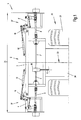
- Fig. 1 shows the machine frame formed as a swing frame 2 of a header 1, e.g. that of a picker for harvesting corn, which in a plan view in working position, i. is shown in unfolded position with the working width 35.
- machine frame is shown as a frame construction, designed as a three-part swing frame 2, wherein this from a first machine frame 3 (middle frame) and second Machine frames 4,4 '(outer frame) exists.
- Middle frame 3 and outer frame 4,4 ' are connected to each other in the hinge joints 18.
- 1a shows the left half of the machine frame according to Figure 1 in an enlarged view.
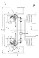
- FIG. 2 shows the transport position of the swing frame 2 of a header attachment 1 according to FIG. 1 with the transport width 36, in which the outer machine frames 4, 4 'are folded inward in the direction of the machine longitudinal center plane 23 by approximately 180 °.
- Emtevorsatzieri 1 of this kind are mainly grown on self-propelled carrier vehicles 24, such as combine harvester or forage harvester before the front wheels 25.
- the drive of the header attachment 1 via a drive train 6 from the engine of the carrier vehicle 24, which branches into further drive trains 7,7 'within a transmission 26, as shown in the example Fig. 1.
- 2a shows the left half of the machine frame according to Figure 2 in an enlarged view.
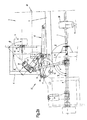
- the folding outer frame parts 4,4 'of the swing frame 2 are carriers for driven machine elements, which are not shown in detail for reasons of clarity, but, as shown in the embodiment Fig.1 or Fig.2, by a gear 26 and the engine of the carrier vehicle 24 are driven off.
- the transmission 5 is driven on the input side by a propeller shaft 8, which is connected to the drive train 7.
- the propeller shaft 8 is the continuation of the drive train 7, 7 '.
- the universal joints 9.10 allow angling of the drive train 7, which is continued by the propeller shaft 8.
- a bearing 27 Between the gear housing 5 and the propeller shaft 8 is a bearing 27 and between the bearing 27 and the gear housing fifth There is a clutch release 11, which is engaged in the operating state and thus can transmit the rotational energy.
- the bearing 27 is supported on a rocker 28, which also serves as a bearing bracket, and firmly connected to this.
- the rocker 28 is pivotally hinged in the hinge point 29 on the outer frame 4.
- the hinge axis 30 of the hinge point 29 is obliquely in space, which has a favorable effect on the movement of the pivoting of the propeller shaft 8 during the folding of the machine frame 4.
- the rocker 28 is held by a coupling rod 31 in its intended position or controlled during the folding of this, the coupling rod 31 is struck in the pivot point 32 on the rocker 28.
- the coupling rod 31 is connected to the lever 21, wherein the lever 21 is fixedly connected to a boom 34.
- Boom 34 and lever 21 thus form a firmly interconnected unit, so that when the lever 21 is pivoted, the boom 34 is also pivoted with.
- the lever 21 is connected in the hinge point 17 with the outer frame 4,4 '. At the free end of the lever 21 is the hinge point 16, at the same time the hinge eye 15 of the piston rod 14 is struck. Also in the pivot point 16 a curved coupling 22 is struck, which is supported in the hinge point 19 of the center frame 3.
- the actuator 12 is acted upon by the driver's seat of the driver so with pressure that the piston rod hineinafter into the interior of the cylinder housing 13, so that the outer frame 4,4 'pivoted about the pivot axis of the hinge joint 18.
- the actuation of the pivot drive 12 also causes a pivoting operation of the lever 21, to which the coupling rod 31 is struck in the hinge point 33. At the other end of the coupling rod 31, this is struck in the pivot point 32 on the rocker 28, so that the rocker 28 is pivoted by entrainment of the coupling rod 31 in the hinge point 29 about the hinge axis 30.
- the pivot angle ⁇ is defined by the pivot angle difference, which is set between the virtual end position 40 of the rocker 28, which would then set when the rocker 28 equally covers the full swing angle ⁇ , and the actual end position 41 of the rocker 28 in the fully opened state transport position.
- the rocker 28 undergoes a change of your space coordinates with respect to the middle frame 3 by the folding operation, and on the other hand a rotation about the pivot angle ⁇ relative to the outer frame 4,4 '.
- the pivot angle ⁇ is enforced or controlled by the coupling movement of the coupling rod 31 with the lever 21.
- a particular inventive advantage is that due to this coupling mechanism 37 consisting of the elements middle frame 3, outer frame 4, actuator 12, coupling 22, lever 21, coupling rod 31 and rocker 28, the pivot angle difference ⁇ especially in the interval limits ⁇ / 2 ⁇ ⁇ / 4 may lie.
- At least one of the coupling halves is biased by a compression spring in the axial direction, so that at least one coupling half 38 or 39 in the event that a rotational angle offset the engaged position has occurred, temporarily as long as the other coupling half can escape until it can engage automatically and completely under the action of the spring force when switching on the drive train 7 again.
- the invention is by no means limited exclusively to agricultural harvesters as attachments, but they can in principle also be applied there in agricultural technology, when it comes to coupling pivotable machine frames to drive trains of the kind set forth.
Landscapes
- Life Sciences & Earth Sciences (AREA)
- Environmental Sciences (AREA)
- Agricultural Machines (AREA)
- Harvesting Machines For Root Crops (AREA)
- Harvester Elements (AREA)
Abstract
Description
Die Erfindung betrifft einen Schwenkrahmen eines Erntevorsatzgerätes bestehend aus wenigstens zwei, einem ersten und einem zweiten Maschinengestell, welche schwenkbeweglich und verklappbar miteinander verbunden sind, wobei das wenigstens zweite und verklappbare Maschinengestell wenigstens ein Antriebselement umfasst, welches antriebsseitig in Wirkverbindung mit dem ersten Maschinengestell steht. Die Verklappung soll insbesondere der Reduzierung der Transportbreite dienen. Dazu ist ein Verklappungswinkel bis zu etwa 180° vorgesehen, wobei der Antriebsstrang eine Gelenkwelle umfasst, die an der Verklappung und damit an der Schwenkbewegung teilnimmt, und wobei die Schwenkbewegung des Antriebsstrangs (Gelenkwelle) über ein Koppelgetriebe so gesteuert wird, dass sie nicht manuell abgekoppelt werden muss.The invention relates to a swing frame of a header unit consisting of at least two, a first and a second machine frame, which are pivotally connected and hinged together, wherein the at least second and folding machine frame comprises at least one drive element, which is the drive side in operative connection with the first machine frame. The dumping is intended in particular to reduce the transport width. For this purpose, a Verklappungswinkel is provided up to about 180 °, wherein the drive train comprises a propeller shaft, which participates in the folding and thus on the pivoting movement, and wherein the pivotal movement of the drive train (propeller shaft) is controlled via a coupling gear so that they are not decoupled manually must become.
Landwirtschaftliche Maschinen mit Schwenkrahmen sind in vielfältiger Art prinzipiell bekannt. Die
In der
Die
Große Klappwinkel etwa die von 180° und mehr verlangen entsprechend große Bauräume mit Weitwinkelkreuzgelenken. Stehen diese Bauräume nicht zur Verfügung muss die Gelenkwelle manuell vor dem Verklappen abgebaut werden, soll sie beim Verklappen nicht beschädigt werden. Dieses bedeutet, dass der Fahrer von seinem Fahrzeug absteigen muss, um das Entkoppeln bzw. das Wiederankoppeln vorzunehmen. Hinzu kommt, dass, wenn der Antrieb der Gelenkwelle in der stark gebeugten Stellung eingeschaltet wird, stark beschädigt werden können oder zu Bruch gehen.Large folding angles such as those of 180 ° and more require correspondingly large installation spaces with wide-angle universal joints. If these installation spaces are not available, the PTO shaft must be manually dismantled before folding it, it should not be damaged when folding. This means that the driver has to dismount his vehicle to do the decoupling or the re-docking. In addition, when the drive of the propeller shaft is turned on in the strongly bent position, it may be severely damaged or broken.
Hier setzt die Erfindung an, um einerseits eine Lösung vorzuschlagen, die ein Absteigen und manuelles Abkoppeln unter den zuvor genannten Bedingungen nicht erfordert und die die Sicherheit der Gelenkwelle gegen Beschädigung im verklappten Zustand erhöht.This is where the invention begins, on the one hand to propose a solution that does not require a dismount and manual uncoupling under the aforementioned conditions and increases the safety of the propeller shaft against damage in the folded state.
Gelöst wird die Aufgabe der Erfindung mit den kennzeichnenden Merkmalen des unabhängigen Anspruchs 1. Weitere vorteilhafte Ausgestaltungen der Erfindung sind den abhängigen Ansprüchen, der Beschreibung und den Figurendarstellungen zu entnehmen.The object of the invention is achieved with the characterizing features of
Die Erfindung sieht dabei vor, den Antriebsstrang zwischen dem ersten und dem wenigstens zweiten Maschinengestell als Gelenkwelle auszugestalten und diese so in Bezug auf die Scharnierachse des Klappgelenks anzuordnen, dass diese sich auf der Rückseite des Scharniergelenks befindet. Dabei wird die Schwenkbewegung der Gelenkwelle durch ein Koppelgetriebe zwangsläufig gesteuert, wobei dieses an dem Schwenkmechanismus angelenkt bzw. mit diesem gekoppelt ist.The invention provides to design the drive train between the first and the at least second machine frame as a propeller shaft and to arrange them with respect to the hinge axis of the hinged joint, that this is located on the back of the hinge joint. In this case, the pivoting movement of the propeller shaft is necessarily controlled by a coupling gear, which is articulated to the pivot mechanism and coupled thereto.
Erfindungsgemäß besteht dabei zwischen dem Bewegungsablauf des Schwenkantriebs und dem Bewegungsablauf von Gelenkwelle und Außenrahmen eine Abhängigkeit derart, dass der Bewegungsablauf der Schwenkbewegung der Gelenkwelle und der Bewegungsablauf der Schwenkbewegung des Außenrahmens durch ein Koppelgetriebe so gesteuert wird, dass die Gelenkwelle beim Zusammenklappen des Schwenkrahmens dem Außenrahmen nacheilt und umgekehrt beim Auseinanderklappen voreilt.According to the invention, there is a dependence between the sequence of movements of the pivot drive and the movement of the hinge shaft and outer frame such that the movement sequence of the pivotal movement of the propeller shaft and the movement of the pivotal movement of the outer frame is controlled by a coupling mechanism, that the propeller shaft lags the outer frame when folding the swing frame and vice versa when unfolding unfolded.
Ein weiterer erfindungsgemäßer Vorteil besteht darin, dass im weiteren Verlauf der Schwenkbewegung dabei der Antriebsstrang zusätzlich und automatisch von dem wenigstens einen Antriebselement des Außenrahmens, welches beispielsweise zum Antrieb von Arbeitswerkzeugen dienen kann, abgekoppelt wird, welches eine Antriebsstrangunterbrechung beinhaltet. Letzteres schützt den Antriebsstrang gegen Überlast bei entsprechend großen Abwinkelungen der Gelenkwelle bei ungewollter Einschaltung im zusammengeklappten Zustand des Schwenkrahmens und schützt ihn dadurch vor Beschädigungen.Another inventive advantage is that in the further course of the pivoting movement while the drive train is additionally and automatically disconnected from the at least one drive element of the outer frame, which may serve, for example, for driving work tools, which includes a powertrain interruption. The latter protects the drive train against overload at correspondingly large bends of the propeller shaft in case of accidental activation in the folded state of the swing frame and protects him from damage.
Der umgekehrte Schwenkvorgang zurück in die Arbeitsstellung hingegen läuft im umgekehrten Sinne ab und versetzt das Antriebssystem zurück in den Antriebsmodus.The reverse pivoting action back to the working position, however, runs in the opposite direction and puts the drive system back into the drive mode.
Nähere Einzelheiten der Erfindung sind den nachfolgenden Figurendarstellungen und deren Beschreibungen zu entnehmen.Further details of the invention are given in the following figure representations and their descriptions.
Es zeigen:
- Fig. 1
- zeigt den Schwenkrahmen eines Erntevorsatzgerätes in einer Draufsicht in Arbeitsstellung
- Fig. 1a
- zeigt einen vergrößerten Ausschnitt aus Fig.1
- Fig. 2
- zeigt den Schwenkrahmen eines Erntevorsatzgerätes in einer Draufsicht in Transportstellung
- Fig. 2a
- zeigt einen vergrößerten Ausschnitt aus Fig.2
- Fig. 1
- shows the swing frame of a header in a plan view in working position
- Fig. 1a
- shows an enlarged section of Fig.1
- Fig. 2
- shows the swing frame of a header in a plan view in transport position
- Fig. 2a
- shows an enlarged section of Figure 2
Fig.1 zeigt das Maschinengestell, ausgebildet als Schwenkrahmen 2 eines Erntevorsatzgerätes 1, z.B. das eines Pflückers zum Ernten von Mais, welches in einer Draufsicht in Arbeitsstellung, d.h. in auseinander geklappter Stellung mit der Arbeitsbreite 35 dargestellt ist.Fig. 1 shows the machine frame formed as a
Aus Gründen der besseren Übersichtlichkeit ist lediglich das Maschinengestell als Rahmenkonstruktion, ausgeführt als dreiteiliger Schwenkrahmen 2 dargestellt, wobei dieser aus einem ersten Maschinengestell 3 (Mittelrahmen) und zweiten Maschinengestellen 4,4' (Außenrahmen) besteht. Mittelrahmen 3 und Außenrahmen 4,4' sind in den Scharniergelenken 18 miteinander verbunden. In dem dargestellten Ausführungsbeispiel befinden sich somit beidseitig der Maschinenlängsmittelebene 23 je ein verklappbares zweites Maschinengestell 4 bzw. 4' als Außenrahmen, welche von je einem Stellantrieb 12, ausgeführt als hydraulisch beaufschlagter Differentialkolbenzylinder, von der Transportposition in die Arbeitsposition und umgekehrt verklappt werden können. Fig.1a zeigt die linke Hälfte des Maschinengestells gemäß Fig.1 in vergrößerter Darstellung.For reasons of clarity, only the machine frame is shown as a frame construction, designed as a three-
Fig.2 zeigt die Transportposition des Schwenkrahmens 2 eines Erntevorsatzgerätes 1 gemäß Fig.1 mit der Transportbreite 36, in der die äußeren Maschinengestelle 4,4' um etwa 180° nach innen in Richtung Maschinenlängsmittelebene 23 verklappt sind. Emtevorsatzgeräte 1 dieser Art werden vornehmlich an selbstfahrende Trägerfahrzeuge 24, wie beispielsweise Mähdrescher oder Feldhäcksler vor deren Vorderrädern 25 angebaut. Der Antrieb des Erntevorsatzgerätes 1 erfolgt über einen Antriebsstrang 6 vom Motor des Trägerfahrzeuges 24, der sich in weitere Antriebsstränge 7,7' innerhalb eines Getriebes 26 verzweigt, wie in dem Beispiel Fig. 1 dargestellt. Fig.2a zeigt die linke Hälfte des Maschinengestells gemäß Fig.2 in vergrößerter Darstellung.2 shows the transport position of the
Die verklappbaren äußeren Rahmenteile 4,4' des Schwenkrahmens 2 sind Träger für angetriebene Maschinenelemente, die aus Gründen der Übersichtlichkeit im Detail nicht dargestellt sind, die aber, wie in dem Ausführungsbeispiel Fig.1 bzw. Fig.2 dargestellt, von einem Getriebe 26 bzw. dem Motor des Trägerfahrzeugs 24 ausgehend abgetrieben werden.The folding
An dem Außenrahmen 4,4' ist ein Getriebe 5 befestigt, von dem aus der Antriebstrang 7 zu wenigstens einem angetriebenen Maschinenelement des Außenrahmen 4,4' weitergeführt wird.On the
Das Getriebe 5 wird dabei eingangsseitig von einer Gelenkwelle 8 angetrieben, welche mit dem Antriebsstrang 7 verbunden ist. Somit stellt die Gelenkwelle 8 die Fortsetzung des Antriebsstrangs 7,7' dar. Die Kreuzgelenke 9.10 ermöglichen ein Abwinkeln des Antriebsstrangs 7, der durch die Gelenkwelle 8 fortgesetzt ist.The
Aber auch der Klappvorgang des Außenrahmens 4,4' wird durch die Beugung der Gelenkwelle 8 ermöglicht. Um bei großen Klappwinkeln α, wie im Ausführungsbeispiel in Fig.2 bzw. Fig.2a dargestellt etwa 180° gerade und insbesondere in räumlich beengten Verhältnissen die Gelenkwelle nicht von Hand abnehmen zu müssen, ist das Getriebe 5 am äußeren Rand des Außenrahmens 4,4' fest angebracht, wobei von dort aus die übrigen nicht dargestellten umlaufend angetriebenen Maschinenelemente mit entsprechenden nicht dargestellten Antriebssträngen angetrieben werden. Dieses ermöglicht es dann eine den räumlichen Grenzen entsprechende Gelenkwelle 8 mit maximaler Baulänge und ebenfalls maximaler Überdeckung der Schiebesitze der Gelenkwelle 8 zu verwenden, so dass beim Verschwenken der Gelenkwelle 8 die erforderliche Überdeckung der Schieberohre der Gelenkwelle stets vorhanden ist.But also the folding operation of the
Zwischen dem Getriebegehäuse 5 und der Gelenkwelle 8 befindet sich eine Lagerstelle 27 und zwischen der Lagerstelle 27 und dem Getriebegehäuse 5 befindet sich eine Ausrückkupplung 11, welche im Betriebszustand eingerückt ist und somit die Drehenergie übertragen kann.Between the
Die Lagerstelle 27 ist dabei auf einer Schwinge 28, die gleichzeitig als Lagerkonsole dient, abgestützt und mit dieser fest verbunden.The
Die Schwinge 28 ist schwenkbar im Gelenkpunkt 29 an dem Außenrahmen 4 angeschlagen. Dabei steht die Gelenkachse 30 des Gelenkpunktes 29 schräg im Raum, welches sich während des Verklappens des Maschinegestells 4 günstig auf den Bewegungsablauf des Verschwenken der Gelenkwelle 8 auswirkt.The
Die Schwinge 28 wird von einer Koppelstange 31 in deren vorgesehener Lage gehalten bzw. während des Verklappens von dieser gesteuert, wobei die Koppelstange 31 im Gelenkpunkt 32 an der Schwinge 28 angeschlagen ist.The
Im Gelenkpunkt 33 ist die Koppelstange 31 mit dem Hebel 21 verbunden, wobei der Hebel 21 mit einem Ausleger 34 fest verbunden ist. Ausleger 34 und Hebel 21 bilden somit eine fest miteinander verbundene Einheit, so dass, wenn der Hebel 21 verschwenkt wird, der Ausleger 34 ebenfalls mit verschwenkt wird.In the
Der Hebel 21 ist im Gelenkpunkt 17 mit dem Außenrahmen 4,4' verbunden. Am freien Ende des Hebels 21 befindet sich der Gelenkpunkt 16, an dem gleichzeitig das Gelenkauge 15 der Kolbenstange 14 angeschlagen ist. Ebenfalls im Gelenkpunkt 16 ist eine gekrümmte Koppel 22 angeschlagen, die sich im Gelenkpunkt 19 des Mittelrahmens 3 abstützt. Hebel 21, Koppel 22 und Stellantrieb 12, ausgeführt als Hydraulikzylinder, bilden einen Schwenkantrieb, dessen Wirkungsweise dem Fachmann prinzipiell bekannt ist und diese daher an dieser Stelle keiner weiteren Erklärung bedarf.The
Um das Erntevorsatzgerät 1 aus der Transportstellung gemäß Fig.1 in die Transportbreite 36 verringernde Stellung gemäß Fig.2 zu verklappen, wird der Stellantrieb 12 vom Fahrersitz des Fahrzeugführers so mit Druck beaufschlagt, dass die Kolbenstange in das Innere des Zylindergehäuses 13 hineinfährt, so dass der Außenrahmen 4,4' um die Schwenkachse des Scharniergelenks 18 verschwenkt.To fold the
Die Betätigung des Schwenkantriebs 12 verursacht auch einen Schwenkvorgang des Hebels 21, an dem die Koppelstange 31 im Gelenkpunkt 33 angeschlagen ist. Am anderen Ende der Koppelstange 31 ist diese im Gelenkpunkt 32 an der Schwinge 28 angeschlagen, so dass die Schwinge 28 durch Mitnahme der Koppelstange 31 im Gelenkpunkt 29 um die Gelenkachse 30 verschwenkt wird.The actuation of the
Während der Außenrahmen 4,4' bis zur Erreichung seiner Endstellung als Transportstellung dabei den Schwenkwinkel α überstreicht, eilt die Schwinge 28 der Schwenkbewegung des Außenrahmens 4,4' um den Schwenkwinkel β nach. Dabei ist der Schwenkwinkel β definiert durch die Schwenkwinkeldifferenz, welche sich einstellt zwischen der virtuellen Endlage 40 der Schwinge 28, die sich dann einstellen würde wenn die Schwinge 28 gleichermaßen den vollen Schwenkwinkel α überstreicht, und der tatsächlichen Endlage 41 der Schwinge 28 im vollverklappten Zustand der Transportstellung.While the
Somit erfährt die Schwinge 28 durch den Klappvorgang eine Änderung Ihrer Raumkoordinaten in Bezug auf den Mittelrahmen 3, und zum Anderen eine Verdrehung um den Schwenkwinkel β relativ zum Außenrahmen 4,4'. Dabei wird der Schwenkwinkel β durch die Koppelbewegung der Koppelstange 31 mit dem Hebel 21 erzwungen bzw. gesteuert.Thus, the
In dieser Abfolge der Schwenkbewegungen, die des Außenrahmens 4,4' und der Schwinge 28 überstreicht die Gelenkwelle 8 den Schwenkwinkel γ, so dass auch die Gelenkwelle 8 der Schwenkbewegung des Außenrahmens 4,4' folgt diesem aber mit abnehmendem Schwenkwinkel β gegenüber dem Schwenkwinkel α nacheilt. In der Endlage des zusammengeklappten Schwenkrahmens 2 ergibt sich somit eine Schwenkwinkeldifferenz δ zwischen dem Schwenkwinkel α des Außenrahmens 4,4' und dem Schwenkwinkel γ der Gelenkwelle 8 nach der Beziehung ![]()
![]()
Ein besonderer erfinderischer Vorteil besteht darin, dass bedingt durch dieses Koppelgetriebe 37 bestehend aus den Elementen Mittelrahmen 3, Außenrahmen 4, Stellantrieb 12, Koppel 22, Hebel 21, Koppelstange 31 und Schwinge 28 die Schwenkwinkeldifferenz δ besonders in den Intervallgrenzen α/2 ± α/4 liegen kann. Damit würde der Schwenkwinkel γ der Gelenkwelle in dem Intervall liegen ![]()
![]()
Dieses führt dazu, dass der Bewegungsablaufs der Gelenkwelle 8 dem Bewegungsablauf des Außenrahmens 4,4' mit deutlich geringerem Beugungswinkel bzw. mit deutlich geringerem Schwenkwinkel γ der Gelenkwelle 8 zurückbleibend nacheilt.This leads to the sequence of movements of the
Da die Schwinge 28 in ihrem Bewegungsablauf ebenfalls der Schwenkbewegung des Außenrahmens 4,4' wegen der Schwenkwinkeldifferenz β nacheilt, eilt diese auch dem Getriebe 5 entsprechend zurückbleibend nach, wodurch die beiden Kupplungshälften 38 und 39 der Ausrückkupplung 11 außer Eingriff gelangen und dadurch der Antriebsstrang 7 zum Getriebe 5 unterbrochen ist. Damit die Kupplungshälften 38,39 beim Ausklappen zurück in die Arbeitsstellung auch dann wieder im eingerückten Zustand formschlüssig zusammenfinden, ist zumindest eine der Kupplungshälften durch eine Druckfeder in axialer Richtung vorgespannt, so dass zumindest eine Kupplungshälfte 38 oder 39 für den Fall, dass eine Drehwinkelverschiebung gegenüber der eingerückten Position stattgefunden hat, vorübergehend solange der anderen Kupplungshälfte ausweichen kann, bis sie bei Einschaltung des Antriebsstrangs 7 automatisch und vollständig unter Einwirkung der Federkraft wieder einrücken kann.Since the
Die Erfindung beschränkt sich keineswegs ausschließlich auf landwirtschaftliche Erntemaschinen als Vorsatzgeräte, sondern sie kann grundsätzlich auch dort in der Landtechnik zur Anwendung gelangen, wenn es darum geht, verschwenkbare Maschinengestelle an Antriebsstränge der dargelegten Art anzukoppeln.The invention is by no means limited exclusively to agricultural harvesters as attachments, but they can in principle also be applied there in agricultural technology, when it comes to coupling pivotable machine frames to drive trains of the kind set forth.
- 11
- ErntevorsatzgerätHarvesting attachment
- 22
- Schwenkrahmen (Maschinegestell)Swing frame (machine frame)
- 33
- Mittelrahmen (erstes Maschinengestell)Middle frame (first machine frame)
- 4,4'4,4 '
- Außenrahmen (zweites Maschinengestell)Outer frame (second machine frame)
- 55
- Getriebe (antreibbares Maschinenelement)Gearbox (drivable machine element)
- 66
- Antriebsstrangpowertrain
- 7,7'7,7 '
- Antriebsstrangpowertrain
- 88th
- Gelenkwelle, (schwenkbeweglicher Tei des Antriebsstrangs)Cardan shaft, (pivoting part of drivetrain)
- 99
- KreuzgelenkUniversal joint
- 1010
- KreuzgelenkUniversal joint
- 1111
- AusrückkupplungCoupling clutches
- 1212
- Stellantriebactuator
- 1313
- Zylindergehäusecylinder housing
- 1414
- Kolbenstangepiston rod
- 1515
- Gelenkaugejoint eye
- 1616
- Gelenkpunktfulcrum
- 1717
- Gelenkpunktfulcrum
- 1818
- Scharniergelenkhinge
- 1919
- Gelenkpunktfulcrum
- 2020
- 2121
- Hebellever
- 2222
- Koppelpaddock
- 2323
- MaschinenlängsmittelebeneMachine longitudinal center plane
- 2424
- Trägerfahrzeugcarrier vehicle
- 2525
- Vorderräderfront wheels
- 2626
- Getriebetransmission
- 2727
- Lagerstelledepository
- 2828
- Schwinge (Winkelhebel)Rocker arm
- 2929
- Gelenkpunktfulcrum
- 3030
- Gelenkachsejoint axis
- 3131
- Koppelstangecoupling rod
- 3232
- Gelenkpunktfulcrum
- 3333
- Gelenkpunktfulcrum
- 3434
- Auslegerboom
- 3535
- Arbeitsbreiteworking width
- 3636
- Transportbreitetransport width
- 3737
- Koppelgetriebecoupling gear
- 3838
- Kupplungshälftecoupling half
- 3939
- Kupplungshälftecoupling half
- 4040
- virtuelle Endlagevirtual end position
- 4141
- tatsächliche Endlageactual end position
- αα
- Schwenkwinkel (Klappwinkel)Swivel angle (folding angle)
- ββ
- Schwenkwinkelswivel angle
- γγ
- Schwenkwinkelswivel angle
- δδ
- SchwenkwinkeldifferenzSwivel angle difference
Claims (10)
Applications Claiming Priority (1)
| Application Number | Priority Date | Filing Date | Title |
|---|---|---|---|
| DE102005046883A DE102005046883A1 (en) | 2005-09-29 | 2005-09-29 | Swing frame of a header for agricultural machines |
Publications (2)
| Publication Number | Publication Date |
|---|---|
| EP1769668A1 true EP1769668A1 (en) | 2007-04-04 |
| EP1769668B1 EP1769668B1 (en) | 2009-02-11 |
Family
ID=37499710
Family Applications (1)
| Application Number | Title | Priority Date | Filing Date |
|---|---|---|---|
| EP06018953A Active EP1769668B1 (en) | 2005-09-29 | 2006-09-11 | Harvester head with pivoting frame for agricultural machines |
Country Status (3)
| Country | Link |
|---|---|
| EP (1) | EP1769668B1 (en) |
| AT (1) | ATE422287T1 (en) |
| DE (2) | DE102005046883A1 (en) |
Cited By (6)
| Publication number | Priority date | Publication date | Assignee | Title |
|---|---|---|---|---|
| ITBO20110606A1 (en) * | 2011-10-28 | 2013-04-29 | Falc S R L | SHAVING MACHINE |
| US9603306B2 (en) | 2014-07-09 | 2017-03-28 | Cnh Industrial America Llc | Agricultural machine with retaining elements for retaining a header in an elevated position |
| US10143138B2 (en) | 2014-04-30 | 2018-12-04 | Cnh Industrial America Llc | Transport system for a center pivot agricultural machine |
| US10194583B2 (en) | 2013-09-11 | 2019-02-05 | Cnh Industrial America Llc | Hitch swing cylinder mounting point repositioning mechanism |
| AT525423A1 (en) * | 2021-09-08 | 2023-03-15 | Georg Hanslauer | Cutting system for weeds to be cut above cultivated plants |
| CN117184712A (en) * | 2023-09-12 | 2023-12-08 | 江苏裕灌现代农业科技有限公司 | Tunnel feeding device for agaricus bisporus stockpiles |
Families Citing this family (2)
| Publication number | Priority date | Publication date | Assignee | Title |
|---|---|---|---|---|
| US9565800B2 (en) | 2014-09-08 | 2017-02-14 | Cnh Industrial America Llc | Windrow shield control system for a header of an agricultural harvester |
| DE102015206142A1 (en) | 2015-04-07 | 2016-10-13 | Maschinenfabrik Kemper Gmbh & Co. Kg | Harvest header for agricultural harvesters |
Citations (4)
| Publication number | Priority date | Publication date | Assignee | Title |
|---|---|---|---|---|
| DE2026190A1 (en) * | 1969-06-02 | 1970-12-23 | Clayson naamloze vennootschap, Zedelgem (Belgien) | Divisible cutting board for combine harvesters |
| DE2000478A1 (en) * | 1970-01-07 | 1971-11-18 | Fahr Ag Maschf | Combine harvesters, in particular self-propelled combine harvesters |
| DE3605933A1 (en) * | 1986-02-25 | 1987-08-27 | Klemens Kalverkamp | Harvesting attachment of a harvesting machine |
| EP0890301A1 (en) * | 1997-06-17 | 1999-01-13 | Claas Saulgau Gmbh | Pivoting frame of a harvester head on agricultural machines for feeding and conveying crops |
-
2005
- 2005-09-29 DE DE102005046883A patent/DE102005046883A1/en not_active Withdrawn
-
2006
- 2006-09-11 DE DE502006002797T patent/DE502006002797D1/en active Active
- 2006-09-11 AT AT06018953T patent/ATE422287T1/en not_active IP Right Cessation
- 2006-09-11 EP EP06018953A patent/EP1769668B1/en active Active
Patent Citations (4)
| Publication number | Priority date | Publication date | Assignee | Title |
|---|---|---|---|---|
| DE2026190A1 (en) * | 1969-06-02 | 1970-12-23 | Clayson naamloze vennootschap, Zedelgem (Belgien) | Divisible cutting board for combine harvesters |
| DE2000478A1 (en) * | 1970-01-07 | 1971-11-18 | Fahr Ag Maschf | Combine harvesters, in particular self-propelled combine harvesters |
| DE3605933A1 (en) * | 1986-02-25 | 1987-08-27 | Klemens Kalverkamp | Harvesting attachment of a harvesting machine |
| EP0890301A1 (en) * | 1997-06-17 | 1999-01-13 | Claas Saulgau Gmbh | Pivoting frame of a harvester head on agricultural machines for feeding and conveying crops |
Cited By (8)
| Publication number | Priority date | Publication date | Assignee | Title |
|---|---|---|---|---|
| ITBO20110606A1 (en) * | 2011-10-28 | 2013-04-29 | Falc S R L | SHAVING MACHINE |
| US10194583B2 (en) | 2013-09-11 | 2019-02-05 | Cnh Industrial America Llc | Hitch swing cylinder mounting point repositioning mechanism |
| US10143138B2 (en) | 2014-04-30 | 2018-12-04 | Cnh Industrial America Llc | Transport system for a center pivot agricultural machine |
| US9603306B2 (en) | 2014-07-09 | 2017-03-28 | Cnh Industrial America Llc | Agricultural machine with retaining elements for retaining a header in an elevated position |
| AT525423A1 (en) * | 2021-09-08 | 2023-03-15 | Georg Hanslauer | Cutting system for weeds to be cut above cultivated plants |
| AT525423B1 (en) * | 2021-09-08 | 2024-07-15 | Georg Hanslauer | Cutting unit for cutting weeds above crops |
| CN117184712A (en) * | 2023-09-12 | 2023-12-08 | 江苏裕灌现代农业科技有限公司 | Tunnel feeding device for agaricus bisporus stockpiles |
| CN117184712B (en) * | 2023-09-12 | 2024-04-12 | 江苏裕灌现代农业科技有限公司 | Tunnel feeding device for agaricus bisporus stockpiles |
Also Published As
| Publication number | Publication date |
|---|---|
| EP1769668B1 (en) | 2009-02-11 |
| ATE422287T1 (en) | 2009-02-15 |
| DE502006002797D1 (en) | 2009-03-26 |
| DE102005046883A1 (en) | 2007-05-31 |
Similar Documents
| Publication | Publication Date | Title |
|---|---|---|
| EP1769668B1 (en) | Harvester head with pivoting frame for agricultural machines | |
| EP1389413B1 (en) | Coupling of a lateral mowing unit and its complementary means to a supporting structure for attachment to a tractor or a carrying vehicle | |
| EP1464214B1 (en) | Harvester for stalk-like crop like maize | |
| EP2111740B1 (en) | Harvesting attachment for harvesting stalk crops | |
| EP2067397B1 (en) | Harvester head to gather and transport cereals in an agricultural harvesting machine | |
| DE102005016350A1 (en) | Harvest header for agricultural harvesters | |
| EP1287731B1 (en) | Drive mechanism for a discharge means of an agricultural harvester | |
| EP1796454B1 (en) | Harvesting equipment, in particular harvesting attachment for agricultural harvesting machines used to gather and transport cereals | |
| DE102004042437A1 (en) | Attachment for harvesters | |
| EP1839480B1 (en) | Rotary windrower | |
| DE102008042392B4 (en) | Harvesting header for agricultural harvesting machines | |
| DE202008005596U1 (en) | Harvesting attachment for harvesting stalky crops | |
| EP3732948A1 (en) | Cutting unit | |
| EP1932414B1 (en) | Mowing machine to be placed on the front end of an agricultural automobile | |
| DE19943208C2 (en) | Drive arrangement with an actuator | |
| EP1378160B1 (en) | Cutting and feeding device for stem crop | |
| AT501972B1 (en) | MOWER | |
| EP1829444B1 (en) | Rotary swather | |
| EP1554919A1 (en) | Coupling of a lateral mowing unit and its complementary means to a supporting structure for attachment to a tractor or a carrier vehicle | |
| EP1982580A2 (en) | Agricultural cultivation device | |
| EP0809927B1 (en) | Separable articulated claw coupling | |
| DE202011000460U1 (en) | Direct cutting unit as a header for a self-propelled forage harvester | |
| DE102006014652A1 (en) | Rotary tedder has at least six rakes mounted on two arms which are angled forward in working position and can be pivoted back about vertical pivots until they are parallel and can then be raised about horizontal pivots to vertical position | |
| DE102006042552A1 (en) | Rotary tedder has at least six rakes mounted on two arms which are angled forward in working position and can be pivoted back about vertical pivots until they are parallel and can then be raised about horizontal pivots to vertical position | |
| DE69914151T2 (en) | agricultural machinery |
Legal Events
| Date | Code | Title | Description |
|---|---|---|---|
| PUAI | Public reference made under article 153(3) epc to a published international application that has entered the european phase |
Free format text: ORIGINAL CODE: 0009012 |
|
| AK | Designated contracting states |
Kind code of ref document: A1 Designated state(s): AT BE BG CH CY CZ DE DK EE ES FI FR GB GR HU IE IS IT LI LT LU LV MC NL PL PT RO SE SI SK TR |
|
| AX | Request for extension of the european patent |
Extension state: AL BA HR MK YU |
|
| 17P | Request for examination filed |
Effective date: 20071004 |
|
| 17Q | First examination report despatched |
Effective date: 20071106 |
|
| AKX | Designation fees paid |
Designated state(s): AT BE BG CH CY CZ DE DK EE ES FI FR GB GR HU IE IS IT LI LT LU LV MC NL PL PT RO SE SI SK TR |
|
| GRAP | Despatch of communication of intention to grant a patent |
Free format text: ORIGINAL CODE: EPIDOSNIGR1 |
|
| RTI1 | Title (correction) |
Free format text: HARVESTER HEAD WITH PIVOTING FRAME FOR AGRICULTURAL MACHINES |
|
| GRAS | Grant fee paid |
Free format text: ORIGINAL CODE: EPIDOSNIGR3 |
|
| GRAA | (expected) grant |
Free format text: ORIGINAL CODE: 0009210 |
|
| AK | Designated contracting states |
Kind code of ref document: B1 Designated state(s): AT BE BG CH CY CZ DE DK EE ES FI FR GB GR HU IE IS IT LI LT LU LV MC NL PL PT RO SE SI SK TR |
|
| REG | Reference to a national code |
Ref country code: GB Ref legal event code: FG4D Free format text: NOT ENGLISH |
|
| REG | Reference to a national code |
Ref country code: CH Ref legal event code: EP |
|
| REG | Reference to a national code |
Ref country code: IE Ref legal event code: FG4D Free format text: LANGUAGE OF EP DOCUMENT: GERMAN |
|
| REF | Corresponds to: |
Ref document number: 502006002797 Country of ref document: DE Date of ref document: 20090326 Kind code of ref document: P |
|
| PG25 | Lapsed in a contracting state [announced via postgrant information from national office to epo] |
Ref country code: FI Free format text: LAPSE BECAUSE OF FAILURE TO SUBMIT A TRANSLATION OF THE DESCRIPTION OR TO PAY THE FEE WITHIN THE PRESCRIBED TIME-LIMIT Effective date: 20090211 Ref country code: SI Free format text: LAPSE BECAUSE OF FAILURE TO SUBMIT A TRANSLATION OF THE DESCRIPTION OR TO PAY THE FEE WITHIN THE PRESCRIBED TIME-LIMIT Effective date: 20090211 Ref country code: NL Free format text: LAPSE BECAUSE OF FAILURE TO SUBMIT A TRANSLATION OF THE DESCRIPTION OR TO PAY THE FEE WITHIN THE PRESCRIBED TIME-LIMIT Effective date: 20090211 Ref country code: ES Free format text: LAPSE BECAUSE OF FAILURE TO SUBMIT A TRANSLATION OF THE DESCRIPTION OR TO PAY THE FEE WITHIN THE PRESCRIBED TIME-LIMIT Effective date: 20090522 Ref country code: LT Free format text: LAPSE BECAUSE OF FAILURE TO SUBMIT A TRANSLATION OF THE DESCRIPTION OR TO PAY THE FEE WITHIN THE PRESCRIBED TIME-LIMIT Effective date: 20090211 |
|
| NLV1 | Nl: lapsed or annulled due to failure to fulfill the requirements of art. 29p and 29m of the patents act | ||
| PG25 | Lapsed in a contracting state [announced via postgrant information from national office to epo] |
Ref country code: SE Free format text: LAPSE BECAUSE OF FAILURE TO SUBMIT A TRANSLATION OF THE DESCRIPTION OR TO PAY THE FEE WITHIN THE PRESCRIBED TIME-LIMIT Effective date: 20090511 Ref country code: IS Free format text: LAPSE BECAUSE OF FAILURE TO SUBMIT A TRANSLATION OF THE DESCRIPTION OR TO PAY THE FEE WITHIN THE PRESCRIBED TIME-LIMIT Effective date: 20090611 Ref country code: PL Free format text: LAPSE BECAUSE OF FAILURE TO SUBMIT A TRANSLATION OF THE DESCRIPTION OR TO PAY THE FEE WITHIN THE PRESCRIBED TIME-LIMIT Effective date: 20090211 Ref country code: LV Free format text: LAPSE BECAUSE OF FAILURE TO SUBMIT A TRANSLATION OF THE DESCRIPTION OR TO PAY THE FEE WITHIN THE PRESCRIBED TIME-LIMIT Effective date: 20090211 |
|
| REG | Reference to a national code |
Ref country code: IE Ref legal event code: FD4D |
|
| PG25 | Lapsed in a contracting state [announced via postgrant information from national office to epo] |
Ref country code: IE Free format text: LAPSE BECAUSE OF FAILURE TO SUBMIT A TRANSLATION OF THE DESCRIPTION OR TO PAY THE FEE WITHIN THE PRESCRIBED TIME-LIMIT Effective date: 20090211 Ref country code: EE Free format text: LAPSE BECAUSE OF FAILURE TO SUBMIT A TRANSLATION OF THE DESCRIPTION OR TO PAY THE FEE WITHIN THE PRESCRIBED TIME-LIMIT Effective date: 20090211 Ref country code: PT Free format text: LAPSE BECAUSE OF FAILURE TO SUBMIT A TRANSLATION OF THE DESCRIPTION OR TO PAY THE FEE WITHIN THE PRESCRIBED TIME-LIMIT Effective date: 20090713 Ref country code: DK Free format text: LAPSE BECAUSE OF FAILURE TO SUBMIT A TRANSLATION OF THE DESCRIPTION OR TO PAY THE FEE WITHIN THE PRESCRIBED TIME-LIMIT Effective date: 20090211 Ref country code: CZ Free format text: LAPSE BECAUSE OF FAILURE TO SUBMIT A TRANSLATION OF THE DESCRIPTION OR TO PAY THE FEE WITHIN THE PRESCRIBED TIME-LIMIT Effective date: 20090211 |
|
| PG25 | Lapsed in a contracting state [announced via postgrant information from national office to epo] |
Ref country code: SK Free format text: LAPSE BECAUSE OF FAILURE TO SUBMIT A TRANSLATION OF THE DESCRIPTION OR TO PAY THE FEE WITHIN THE PRESCRIBED TIME-LIMIT Effective date: 20090211 Ref country code: RO Free format text: LAPSE BECAUSE OF FAILURE TO SUBMIT A TRANSLATION OF THE DESCRIPTION OR TO PAY THE FEE WITHIN THE PRESCRIBED TIME-LIMIT Effective date: 20090211 |
|
| PLBE | No opposition filed within time limit |
Free format text: ORIGINAL CODE: 0009261 |
|
| STAA | Information on the status of an ep patent application or granted ep patent |
Free format text: STATUS: NO OPPOSITION FILED WITHIN TIME LIMIT |
|
| 26N | No opposition filed |
Effective date: 20091112 |
|
| PG25 | Lapsed in a contracting state [announced via postgrant information from national office to epo] |
Ref country code: BG Free format text: LAPSE BECAUSE OF FAILURE TO SUBMIT A TRANSLATION OF THE DESCRIPTION OR TO PAY THE FEE WITHIN THE PRESCRIBED TIME-LIMIT Effective date: 20090511 |
|
| BERE | Be: lapsed |
Owner name: CLAAS SAULGAU G.M.B.H. Effective date: 20090930 |
|
| PG25 | Lapsed in a contracting state [announced via postgrant information from national office to epo] |
Ref country code: MC Free format text: LAPSE BECAUSE OF NON-PAYMENT OF DUE FEES Effective date: 20090930 |
|
| REG | Reference to a national code |
Ref country code: FR Ref legal event code: ST Effective date: 20100531 |
|
| PG25 | Lapsed in a contracting state [announced via postgrant information from national office to epo] |
Ref country code: FR Free format text: LAPSE BECAUSE OF NON-PAYMENT OF DUE FEES Effective date: 20090930 |
|
| PG25 | Lapsed in a contracting state [announced via postgrant information from national office to epo] |
Ref country code: BE Free format text: LAPSE BECAUSE OF NON-PAYMENT OF DUE FEES Effective date: 20090930 |
|
| PG25 | Lapsed in a contracting state [announced via postgrant information from national office to epo] |
Ref country code: GR Free format text: LAPSE BECAUSE OF FAILURE TO SUBMIT A TRANSLATION OF THE DESCRIPTION OR TO PAY THE FEE WITHIN THE PRESCRIBED TIME-LIMIT Effective date: 20090512 |
|
| PG25 | Lapsed in a contracting state [announced via postgrant information from national office to epo] |
Ref country code: AT Free format text: LAPSE BECAUSE OF NON-PAYMENT OF DUE FEES Effective date: 20090911 |
|
| PG25 | Lapsed in a contracting state [announced via postgrant information from national office to epo] |
Ref country code: IT Free format text: LAPSE BECAUSE OF FAILURE TO SUBMIT A TRANSLATION OF THE DESCRIPTION OR TO PAY THE FEE WITHIN THE PRESCRIBED TIME-LIMIT Effective date: 20090211 |
|
| PG25 | Lapsed in a contracting state [announced via postgrant information from national office to epo] |
Ref country code: LU Free format text: LAPSE BECAUSE OF NON-PAYMENT OF DUE FEES Effective date: 20090911 |
|
| REG | Reference to a national code |
Ref country code: CH Ref legal event code: PL |
|
| GBPC | Gb: european patent ceased through non-payment of renewal fee |
Effective date: 20100911 |
|
| PG25 | Lapsed in a contracting state [announced via postgrant information from national office to epo] |
Ref country code: HU Free format text: LAPSE BECAUSE OF FAILURE TO SUBMIT A TRANSLATION OF THE DESCRIPTION OR TO PAY THE FEE WITHIN THE PRESCRIBED TIME-LIMIT Effective date: 20090812 |
|
| PG25 | Lapsed in a contracting state [announced via postgrant information from national office to epo] |
Ref country code: LI Free format text: LAPSE BECAUSE OF NON-PAYMENT OF DUE FEES Effective date: 20100930 Ref country code: CH Free format text: LAPSE BECAUSE OF NON-PAYMENT OF DUE FEES Effective date: 20100930 |
|
| PG25 | Lapsed in a contracting state [announced via postgrant information from national office to epo] |
Ref country code: TR Free format text: LAPSE BECAUSE OF FAILURE TO SUBMIT A TRANSLATION OF THE DESCRIPTION OR TO PAY THE FEE WITHIN THE PRESCRIBED TIME-LIMIT Effective date: 20090211 Ref country code: GB Free format text: LAPSE BECAUSE OF NON-PAYMENT OF DUE FEES Effective date: 20100911 |
|
| PG25 | Lapsed in a contracting state [announced via postgrant information from national office to epo] |
Ref country code: CY Free format text: LAPSE BECAUSE OF FAILURE TO SUBMIT A TRANSLATION OF THE DESCRIPTION OR TO PAY THE FEE WITHIN THE PRESCRIBED TIME-LIMIT Effective date: 20090211 |
|
| P01 | Opt-out of the competence of the unified patent court (upc) registered |
Effective date: 20230511 |
|
| PGFP | Annual fee paid to national office [announced via postgrant information from national office to epo] |
Ref country code: DE Payment date: 20230920 Year of fee payment: 18 |