EP1767793A2 - Mounting device for the attachment of solar panels with an assembly rail - Google Patents
Mounting device for the attachment of solar panels with an assembly rail Download PDFInfo
- Publication number
- EP1767793A2 EP1767793A2 EP06120779A EP06120779A EP1767793A2 EP 1767793 A2 EP1767793 A2 EP 1767793A2 EP 06120779 A EP06120779 A EP 06120779A EP 06120779 A EP06120779 A EP 06120779A EP 1767793 A2 EP1767793 A2 EP 1767793A2
- Authority
- EP
- European Patent Office
- Prior art keywords
- fastening device
- fastening
- screw
- portions
- solar panels
- Prior art date
- Legal status (The legal status is an assumption and is not a legal conclusion. Google has not performed a legal analysis and makes no representation as to the accuracy of the status listed.)
- Withdrawn
Links
- 238000003780 insertion Methods 0.000 claims description 10
- 230000037431 insertion Effects 0.000 claims description 10
- 230000006835 compression Effects 0.000 claims description 8
- 238000007906 compression Methods 0.000 claims description 8
- 229910052751 metal Inorganic materials 0.000 claims description 3
- 239000002184 metal Substances 0.000 claims description 3
- 125000006850 spacer group Chemical group 0.000 description 5
- 238000000034 method Methods 0.000 description 4
- 238000004519 manufacturing process Methods 0.000 description 3
- 238000005452 bending Methods 0.000 description 2
- 239000000463 material Substances 0.000 description 2
- 229910000639 Spring steel Inorganic materials 0.000 description 1
- 229910052782 aluminium Inorganic materials 0.000 description 1
- XAGFODPZIPBFFR-UHFFFAOYSA-N aluminium Chemical compound [Al] XAGFODPZIPBFFR-UHFFFAOYSA-N 0.000 description 1
- 230000015572 biosynthetic process Effects 0.000 description 1
- 238000011161 development Methods 0.000 description 1
- 230000018109 developmental process Effects 0.000 description 1
- 238000009434 installation Methods 0.000 description 1
- 239000004922 lacquer Substances 0.000 description 1
- 238000004080 punching Methods 0.000 description 1
Images


Classifications
-
- F—MECHANICAL ENGINEERING; LIGHTING; HEATING; WEAPONS; BLASTING
- F16—ENGINEERING ELEMENTS AND UNITS; GENERAL MEASURES FOR PRODUCING AND MAINTAINING EFFECTIVE FUNCTIONING OF MACHINES OR INSTALLATIONS; THERMAL INSULATION IN GENERAL
- F16B—DEVICES FOR FASTENING OR SECURING CONSTRUCTIONAL ELEMENTS OR MACHINE PARTS TOGETHER, e.g. NAILS, BOLTS, CIRCLIPS, CLAMPS, CLIPS OR WEDGES; JOINTS OR JOINTING
- F16B5/00—Joining sheets or plates, e.g. panels, to one another or to strips or bars parallel to them
- F16B5/06—Joining sheets or plates, e.g. panels, to one another or to strips or bars parallel to them by means of clamps or clips
- F16B5/0607—Joining sheets or plates, e.g. panels, to one another or to strips or bars parallel to them by means of clamps or clips joining sheets or plates to each other
- F16B5/0621—Joining sheets or plates, e.g. panels, to one another or to strips or bars parallel to them by means of clamps or clips joining sheets or plates to each other in parallel relationship
- F16B5/0628—Joining sheets or plates, e.g. panels, to one another or to strips or bars parallel to them by means of clamps or clips joining sheets or plates to each other in parallel relationship allowing for adjustment parallel or perpendicular to the plane of the sheets or plates
-
- F—MECHANICAL ENGINEERING; LIGHTING; HEATING; WEAPONS; BLASTING
- F16—ENGINEERING ELEMENTS AND UNITS; GENERAL MEASURES FOR PRODUCING AND MAINTAINING EFFECTIVE FUNCTIONING OF MACHINES OR INSTALLATIONS; THERMAL INSULATION IN GENERAL
- F16B—DEVICES FOR FASTENING OR SECURING CONSTRUCTIONAL ELEMENTS OR MACHINE PARTS TOGETHER, e.g. NAILS, BOLTS, CIRCLIPS, CLAMPS, CLIPS OR WEDGES; JOINTS OR JOINTING
- F16B5/00—Joining sheets or plates, e.g. panels, to one another or to strips or bars parallel to them
- F16B5/02—Joining sheets or plates, e.g. panels, to one another or to strips or bars parallel to them by means of fastening members using screw-thread
- F16B5/0283—Joining sheets or plates, e.g. panels, to one another or to strips or bars parallel to them by means of fastening members using screw-thread with an externally threaded sleeve around the neck or the head of the screw-threaded element for adjustably fastening a plate or frame or the like to a fixed element
-
- F—MECHANICAL ENGINEERING; LIGHTING; HEATING; WEAPONS; BLASTING
- F24—HEATING; RANGES; VENTILATING
- F24S—SOLAR HEAT COLLECTORS; SOLAR HEAT SYSTEMS
- F24S25/00—Arrangement of stationary mountings or supports for solar heat collector modules
- F24S25/30—Arrangement of stationary mountings or supports for solar heat collector modules using elongate rigid mounting elements extending substantially along the supporting surface, e.g. for covering buildings with solar heat collectors
-
- F—MECHANICAL ENGINEERING; LIGHTING; HEATING; WEAPONS; BLASTING
- F24—HEATING; RANGES; VENTILATING
- F24S—SOLAR HEAT COLLECTORS; SOLAR HEAT SYSTEMS
- F24S25/00—Arrangement of stationary mountings or supports for solar heat collector modules
- F24S25/60—Fixation means, e.g. fasteners, specially adapted for supporting solar heat collector modules
- F24S25/63—Fixation means, e.g. fasteners, specially adapted for supporting solar heat collector modules for fixing modules or their peripheral frames to supporting elements
- F24S25/634—Clamps; Clips
- F24S25/636—Clamps; Clips clamping by screw-threaded elements
-
- F—MECHANICAL ENGINEERING; LIGHTING; HEATING; WEAPONS; BLASTING
- F24—HEATING; RANGES; VENTILATING
- F24S—SOLAR HEAT COLLECTORS; SOLAR HEAT SYSTEMS
- F24S25/00—Arrangement of stationary mountings or supports for solar heat collector modules
- F24S25/60—Fixation means, e.g. fasteners, specially adapted for supporting solar heat collector modules
- F24S2025/6004—Fixation means, e.g. fasteners, specially adapted for supporting solar heat collector modules by clipping, e.g. by using snap connectors
-
- F—MECHANICAL ENGINEERING; LIGHTING; HEATING; WEAPONS; BLASTING
- F24—HEATING; RANGES; VENTILATING
- F24S—SOLAR HEAT COLLECTORS; SOLAR HEAT SYSTEMS
- F24S25/00—Arrangement of stationary mountings or supports for solar heat collector modules
- F24S2025/80—Special profiles
- F24S2025/807—Special profiles having undercut grooves
-
- Y—GENERAL TAGGING OF NEW TECHNOLOGICAL DEVELOPMENTS; GENERAL TAGGING OF CROSS-SECTIONAL TECHNOLOGIES SPANNING OVER SEVERAL SECTIONS OF THE IPC; TECHNICAL SUBJECTS COVERED BY FORMER USPC CROSS-REFERENCE ART COLLECTIONS [XRACs] AND DIGESTS
- Y02—TECHNOLOGIES OR APPLICATIONS FOR MITIGATION OR ADAPTATION AGAINST CLIMATE CHANGE
- Y02B—CLIMATE CHANGE MITIGATION TECHNOLOGIES RELATED TO BUILDINGS, e.g. HOUSING, HOUSE APPLIANCES OR RELATED END-USER APPLICATIONS
- Y02B10/00—Integration of renewable energy sources in buildings
- Y02B10/20—Solar thermal
-
- Y—GENERAL TAGGING OF NEW TECHNOLOGICAL DEVELOPMENTS; GENERAL TAGGING OF CROSS-SECTIONAL TECHNOLOGIES SPANNING OVER SEVERAL SECTIONS OF THE IPC; TECHNICAL SUBJECTS COVERED BY FORMER USPC CROSS-REFERENCE ART COLLECTIONS [XRACs] AND DIGESTS
- Y02—TECHNOLOGIES OR APPLICATIONS FOR MITIGATION OR ADAPTATION AGAINST CLIMATE CHANGE
- Y02E—REDUCTION OF GREENHOUSE GAS [GHG] EMISSIONS, RELATED TO ENERGY GENERATION, TRANSMISSION OR DISTRIBUTION
- Y02E10/00—Energy generation through renewable energy sources
- Y02E10/40—Solar thermal energy, e.g. solar towers
- Y02E10/47—Mountings or tracking
Definitions
- the invention relates to a fastening device for the attachment of solar panels to a mounting rail, referred to in the preamble of claim 1. Art.
- support systems are each provided with an assembly opening having mounting rails, which receive the individual solar panels at a distance from the roof covering, such as roof tiles.
- the individual solar panels are fixed against wind and snow loads.
- a fastening system for solar panels in which a mounting rail has a limited as a mounting opening a longitudinal groove in which a nut member with an internal thread must be inserted laterally.
- a hold-down element and clamping a guided through this fastening screw which has an engaging means and a protruding screw shaft and which engages in the internal thread in the nut member, the solar panel is fixed to the mounting rail. Due to the longitudinal extent of the fastening screw extends the longitudinal axis of the fastening device.
- a disadvantage of the known solution is that the insertion of the nut member in the longitudinal groove, especially in long mounting rails, and the positioning of the nut member for engagement of the fastening screw due to the large number of individual, loose parts is cumbersome.
- a fastening arrangement for the attachment of a component to a C-shaped mounting rail which comprises a rear engagement part, which is insertable into an assembly opening and rotatable for engaging behind the free edges of the mounting opening, a fastening screw, a stop and a hold-down element. Between the stop and the hold-down element, a compression spring is provided. The individual parts are preassembled and made available to the user as a fastening device.
- the rear grip part could be made rotatable relative to the hold-down element, so that the fastening arrangement can be placed with one another even at small distances between the solar panels.
- the rear engagement part must be sufficiently firmly connected for setting with the fastening screw and be easily detachable again for bracing the fastening arrangement of the fastening screw.
- a securing lacquer could be provided between the rear grip part and the fastening screw.
- the breakaway torque must be low so that the fastening screw can be tightened by hand.
- the object of the invention is to provide a fastening device for the attachment of solar panels to a mounting rail, which is easy to assemble and has a small number of interconnected items.
- a fastening device for fixing solar panels to a mounting rail which has a mounting opening limited by edges, a hold-down element for holding down the solar panels, a nut member for clamping the fastening device to the mounting rail and a fastening screw.
- the fastening screw has an engagement means and a screw shaft projecting therefrom. Through the longitudinal extent of the fastening screw extends a longitudinal axis of the fastening device.
- a connecting element which has a connecting portion and at least two spring-elastic sections projecting therefrom, which extend parallel to the longitudinal axis of the fastening device and in its free end portion a holding portion and a spaced from the holding portion in the direction of the connecting portion projection for forming a first receiving space for the inclusion of, the mounting opening limiting edges.
- a gap is formed between the resilient sections.
- the holding portions and the projections are arranged on the side facing away from the gap side of the resilient portions.
- a spring element is provided which is supported on the one hand on the nut member and on the other hand on the hold-down element.
- the nut member is disposed on the connecting portion such that the fastening screw is coaxially guided in the gap.
- the elastic sections are advantageously arranged at the same distance from the longitudinal axis of the fastening device for the formation of the intermediate space.
- these form in cross section, for example, a polygonal or circular configuration.
- the distance between the mounting rail to one of the hold-down portions of the hold-down element provided by the connecting element and the spring element is such chosen that solar panels with different heights with one and the same fastening device can be fixed to the mounting rails.
- the snapped on the mounting rail fastening device is displaceable for positioning along the mounting hole. Subsequently, the fastening screw is clamped, wherein the height of the hold-down element is reduced to the mounting rail against the spring force of the spring element until the hold-down of the hold-down element comes into contact with the top of the solar panels.
- the length of the fastening screw is chosen such that in the clamped state of the fastening device, the free end of the fastening screw penetrates into the mounting hole. Further advantageous is the screw diameter of the fastening screw chosen such that the resilient portions are pressed in the region of the mounting opening bounding edges of this and unintentional release of the fastening device is prevented under load.
- the low element advantageously has parallel side surfaces extending in the direction of the connecting element, which are guided at least as far as the connecting section of the connecting element.
- the inventive fastening device is easy to install and due to the few, easily manufacturable items inexpensive to produce, which is a significant advantage especially for a mass product, as it represents such a fastening device.
- the projection extends to form a second receiving space for a portion of the screw shaft of the fastening screw in the direction of the connecting portion.
- the fastening screw penetrates maximally to the axial position of the projections relative to the longitudinal axis of the fastening device in the intermediate space formed by the resilient sections, so that the free end of the fastening screw is encompassed upon compression of the resilient sections of these and thus limits the pivotability of the elastic sections only in the desired frame.
- insertion portions are provided at the free ends of the resilient portions projecting from the holding portions facing each other.
- the insertion sections advantageously form a conical tip as an insertion aid when setting the Fastening device, so that the fastening device in the pre-assembly only has to be clipped into the mounting hole, wherein the resilient portions are pressed together and embrace this after reaching the position for gripping the edges of the mounting hole.
- the fastening device according to the invention is ensured by the Einclipsvorgang a simple installation, wherein all operations take place from the outside and, for example, does not have to be used between two adjacent solar panels for their fixation.
- the insertion sections for forming the insertion aid for the fastening device for example, also have a convex outer contour.
- the connecting element is formed substantially U-shaped, wherein the resilient portions form the legs of the U-shaped connecting element.
- This connecting element is particularly easy to produce.
- the spring element is designed as a leaf spring.
- the free edges of the leaf spring come with the hold-down element in abutment and a central portion of the leaf spring is supported on the nut member, wherein the central portion has a passage opening for the fastening screw.
- the spring element is held on the nut member.
- the spring element is merely fixed to the nut element. With the spring element, a sufficient distance of the hold-down to the mounting rail is ensured in the pre-assembly of the fastening device, so that the mounting device solar panels with different heights on the mounting rail can be fixed.
- the spring element is designed as a compression spring.
- the compression spring is either supported on the nut member or is held by this or is fixed to this.
- a sheet metal portion is preferably provided as rotation on the nut member, which advantageously extends between the side surfaces of the hold-down element.
- the fastening device is exposed to the weather and is therefore advantageously made of aluminum and stainless materials. As far as possible, all parts in made a punching / bending process, which allows a cost-effective production of the fastening device.
- a T-section is created and then bent the two flanks to the outside. This creates a straight bearing edge, which comes in the set state of the fastening device, with the mounting rail in abutment. This method is also applicable to difficult to machine materials.
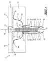
- the fastening device 11 With the fastening device 11 shown in FIGS. 1 to 3, solar panels 1 are fastened to a mounting rail 2, which has a mounting opening 3 limited by edges 4.
- the fastening device 11 comprises a hold-down element 12 for holding down the solar panels 1, a threaded rivet as a nut element 21 for clamping the fastening device 11 to the mounting rail 2 and a fastening screw 22.
- the fastening screw 22 has as an engaging means 23 a hexagon socket and a screw shank 24, starting from its free end 25, at least partially provided with an external thread. Due to the longitudinal extent of the fastening screw 22, a longitudinal axis 26 of the fastening device 11 extends.
- the hold-down element 12 has two opposing hold-down portions 13 which come into abutment with the solar panels 1 in the clamped state of the fastening device 11, a spacer portion 14 which is provided with a passage opening 15 for the fastening screw 22, and respectively the spacer portion 14 with the hold-down portions 13th connecting sections 16 on. Further, the hold-down element 12 is provided with two side walls 17 aligned parallel to one another, which extend on the side of the spacer section 14 facing away from the hold-down sections 13.
- the fastening device 11 further comprises a made of a spring steel in a stamping / bending process, substantially U-shaped connecting element 31, which has a connecting portion 32 and two projecting resilient portions 33 thereof, in the relaxed state of the connecting element 31 substantially parallel to the longitudinal axis 26 of the fastening device 11 extend. Between the resilient portions 33, a gap 36 is formed. At its end region, the resilient sections 33 have a first receiving space 37 for receiving in portions the edges 4 of the mounting opening 3, which is formed by a holding portion 34 and a projection 35 spaced from the holding portion 34 in the direction of the connecting portion 32. The holding portion 34 and the projection 35 are arranged on the side facing away from the gap 36 side 38 of the resilient portions 33.
- the projection 35 extends in the direction of the connecting portion 32 and thereby forms a second receiving space 39 for a portion of the screw shaft 24 of the fastening screw 22, which extends from the free end 25 of the screw shaft 24.
- the free edge of the projections 35 creates a sufficient bearing surface of the connecting element 31 on the outside 5 of the mounting rail 2.
- insertion portions 40 are provided, which protrude from the holding portions 34 facing each other and a conical tip as an insertion aid for Form fastening device 11.
- the fastening device 11 a leaf spring 47 as a spring element 46, which on the one hand with a central portion 48 which is fixed to the nut member 21, on the nut member 21 and on the other hand with the free ends 49 of the leaf spring 47 at the spacer portion 14 of the hold-down element 12th supported.
- FIGS. 2 a to 2 c the mounting operation for fixing solar panels 1 to the mounting rail 2 with the fastening device 11 will be described.
- the solar panels 1 are laid at a distance from each other on a grid created with the mounting rails 2.
- the fastening device 11 between two solar panels 1 in the direction of the arrow 51 is inserted (Fig. 2a).
- the resilient portions 33 of the connecting element 31 are compressed, wherein the free end 25 of the fastening screw 22 in the second, of the projections 35, in the direction extending the connecting portion 32, formed receiving space 39 is received.
- the connecting element 31 snaps in and the edges 4 of the mounting opening 3 are received by the first receiving spaces 37 (FIG. 2 b), whereby the fastening device 11 moves along the mounting opening 3 slidably held on the mounting rail 2.
- the fastening device 11 is clamped to the mounting rail 2 by actuating the fastening screw 22 (FIG. 2c).
- the hold-down element 12 is moved counter to the spring force of the leaf spring 47 in the direction of the mounting rail 2 until the hold-down sections 13 of the hold-down element 12 come into contact with the solar panels.
- the free end 25 of the screw shaft 24 penetrates during bracing between the resilient portions 33 in the mounting hole 3, wherein the resilient portions 33 are pressed against the edges 4 of the mounting hole 3.
- the solar panels 1 are fixed with the inventive fastening device 11 against tensile and compressive stress on the mounting rail 2.
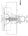
- the fastening device 61 shown in Fig. 4 differs from the fastening device 11 in particular by the configuration of the spring element 66.
- the spring element 66 is formed as a compression spring 67 which is supported on the one hand on the nut member 71 and on the other hand on the spacer portion 74 of the hold-down element 72.
- the fastening screw 62 is passed through the compression spring 67.
- a sheet metal section 69 is provided with angled edges between the side walls 77 of the hold-down element 72.
Abstract
Description
Die Erfindung betrifft eine Befestigungsvorrichtung für die Befestigung von Solarpaneelen an einer Montageschiene, der im Oberbegriff des Patentanspruchs 1 genannten Art.The invention relates to a fastening device for the attachment of solar panels to a mounting rail, referred to in the preamble of claim 1. Art.
Um Solaranlagen auf Dachflächen, insbesondere nachträglich zu installieren, werden Tragsysteme aus jeweils eine Montageöffnung aufweisenden Montageschienen vorgesehen, welche die einzelnen Solarpaneelen in einem Abstand zu der Dachbedeckung, wie Dachziegeln, aufnehmen. Mittels einzelner Befestigungsvorrichtungen sind die einzelnen Solarpaneelen gegen Wind- und Schneelasten fixiert.In order to install solar systems on roof surfaces, in particular subsequently, support systems are each provided with an assembly opening having mounting rails, which receive the individual solar panels at a distance from the roof covering, such as roof tiles. By means of individual fastening devices, the individual solar panels are fixed against wind and snow loads.
Aus der
Nachteilig an der bekannten Lösung ist, dass das Einführen des Mutterelementes in die längsverlaufende Nut, insbesondere bei langen Montageschienen, und die Positionierung des Mutterelementes für den Eingriff der Befestigungsschraube aufgrund der Vielzahl einzelner, loser Teile umständlich ist.A disadvantage of the known solution is that the insertion of the nut member in the longitudinal groove, especially in long mounting rails, and the positioning of the nut member for engagement of the fastening screw due to the large number of individual, loose parts is cumbersome.
Aus der
Nachteilig an der bekannten Lösung ist, dass diese Befestigungsanordnung viele Einzelteile umfasst und daher aufwändig in der Herstellung ist. Zudem muss zum Setzen der Befestigungsanordnung diese in die C-förmige Montageschiene eingedreht werden. Da das Niederhalteelement bei Befestigungsanordnungen für Solarpaneele zumeist über 100 mm lang ist, wird dazu ein sehr grosser Abstand zwischen den Solarpaneelen benötigt, welcher jedoch aus Gründen der benötigten Platzverhältnisse auf ein Minimum reduziert werden sollte.A disadvantage of the known solution is that this fastening arrangement comprises many individual parts and therefore is expensive to manufacture. In addition, to set the mounting arrangement, these must be screwed into the C-shaped mounting rail. Since the hold-down element in mounting arrangements for solar panels is usually over 100 mm long, a very large distance between the solar panels is required, which, however, should be reduced to a minimum for reasons of space required.
Alternativ könnte das Hintergreifteil gegenüber dem Niederhalteelement drehbar ausgeführt werden, so dass die Befestigungsanordnung auch bei geringen Abständen der Solarpaneele untereinander setzbar ist. Für eine ausreichende Gebrauchstauglichkeit einer solchen Befestigungsanordnung muss das Hintergreifteil zum Setzen mit der Befestigungsschraube ausreichend fest verbunden und zum Verspannen der Befestigungsanordnung von der Befestigungsschraube wieder leicht lösbar sein. Beispielsweise könnte ein Sicherungslack zwischen dem Hintergreifteil und der Befestigungsschraube vorgesehen werden. Das Losbrechmoment muss jedoch gering sein, damit die Befestigungsschraube von Hand angezogen werden kann. Diese unterschiedlichen Erfordernisse können nur mit einem zusätzlichen Montageaufwand bei der Herstellung der Befestigungsanordnung abgedeckt werden.Alternatively, the rear grip part could be made rotatable relative to the hold-down element, so that the fastening arrangement can be placed with one another even at small distances between the solar panels. For a sufficient serviceability of such a fastening arrangement, the rear engagement part must be sufficiently firmly connected for setting with the fastening screw and be easily detachable again for bracing the fastening arrangement of the fastening screw. For example, a securing lacquer could be provided between the rear grip part and the fastening screw. However, the breakaway torque must be low so that the fastening screw can be tightened by hand. These different requirements can only be covered with an additional assembly effort in the manufacture of the mounting arrangement.
Aufgabe der Erfindung ist es, eine Befestigungsvorrichtung für die Befestigung von Solarpaneelen an einer Montageschiene zu schaffen, die einfach zu montieren ist und eine geringe Anzahl von miteinander verbundenen Einzelteilen aufweist.The object of the invention is to provide a fastening device for the attachment of solar panels to a mounting rail, which is easy to assemble and has a small number of interconnected items.
Die Aufgabe ist durch die Merkmale des unabhängigen Anspruchs gelöst. Vorteilhafte Weiterbildungen sind in den Unteransprüchen dargelegt.The object is solved by the features of the independent claim. Advantageous developments are set forth in the subclaims.
Gemäss der Erfindung umfasst eine Befestigungsvorrichtung für die Befestigung von Solarpaneelen an einer Montageschiene, die eine von Rändern begrenzte Montageöffnung aufweist, ein Niederhalteelement zum Niederhalten der Solarpaneelen, ein Mutterelement zum Verspannen der Befestigungsvorrichtung an der Montageschiene und eine Befestigungsschraube. Die Befestigungsschraube weist ein Angriffsmittel sowie einen davon abragenden Schraubenschaft auf. Durch die Längserstreckung der Befestigungsschraube verläuft eine Längsachse der Befestigungsvorrichtung. Weiter ist ein Verbindungselement vorgesehen, das einen Verbindungsabschnitt und zumindest zwei davon abragende federelastische Abschnitte aufweist, die parallel zu der Längsachse der Befestigungsvorrichtung verlaufen sowie in ihrem freien Endbereich einen Halteabschnitt und einen zu dem Halteabschnitt in Richtung des Verbindungsabschnitts beabstandeten Vorsprung zur Ausbildung eines ersten Aufnahmeraums für die Aufnahme der, die Montageöffnung begrenzenden Ränder aufweisen. Zwischen den federelastischen Abschnitten ist ein Zwischenraum ausgebildet. Die Halteabschnitte und die Vorsprünge sind an der von dem Zwischenraum abgewandten Seite der federelastischen Abschnitte angeordnet. Weiter ist ein Federelement vorgesehen, das sich einerseits an dem Mutterelement und andererseits an dem Niederhalteelement abstützt. Das Mutterelement ist derart an dem Verbindungsabschnitt angeordnet, dass die Befestigungsschraube koaxial in dem Zwischenraum geführt ist.According to the invention, a fastening device for fixing solar panels to a mounting rail, which has a mounting opening limited by edges, a hold-down element for holding down the solar panels, a nut member for clamping the fastening device to the mounting rail and a fastening screw. The fastening screw has an engagement means and a screw shaft projecting therefrom. Through the longitudinal extent of the fastening screw extends a longitudinal axis of the fastening device. Furthermore, a connecting element is provided, which has a connecting portion and at least two spring-elastic sections projecting therefrom, which extend parallel to the longitudinal axis of the fastening device and in its free end portion a holding portion and a spaced from the holding portion in the direction of the connecting portion projection for forming a first receiving space for the inclusion of, the mounting opening limiting edges. Between the resilient sections, a gap is formed. The holding portions and the projections are arranged on the side facing away from the gap side of the resilient portions. Next, a spring element is provided which is supported on the one hand on the nut member and on the other hand on the hold-down element. The nut member is disposed on the connecting portion such that the fastening screw is coaxially guided in the gap.
Die federelastischen Abschnitte sind für die Ausbildung des Zwischenraums vorteilhaft im gleichen Abstand zu der Längsachse der Befestigungsvorrichtung angeordnet. Bei mehr als zwei federelastischen Abschnitten formen diese im Querschnitt beispielsweise eine polygonale oder kreisförmige Ausgestaltung. Durch Zusammendrücken der federelastischen Abschnitte des Verbindungselement lässt sich die Befestigungsvorrichtung in die Montageöffnung einführen, wobei die von den Halteabschnitten und den dazu beabstandeten Vorsprüngen geschaffenen ersten Aufnahmeräume in eine Position zur bereichsweisen Aufnahme der die Montageöffnung begrenzenden Ränder gebracht werden. Für eine einfache Montage dringt im vormontierten Zustand der Befestigungsvorrichtung das freie Ende der Befestigungsschraube nur bereichsweise in den von den federelastischen Abschnitten geschaffenen Zwischenraum ein, so dass sich die federelastischen Abschnitte leicht zusammendrücken lassen. Durch Entlasten der federelastischen Abschnitte streben diese voneinander weg, wobei die Ränder der Montageöffnung von den Halteabschnitten und den dazu beabstandeten Vorsprüngen umgriffen werden. Der von dem Verbindungselement und dem Federelement geschaffene Abstand zwischen der Montageschiene zu einem der Niederhalteabschnitte des Niederhalteelements ist derart gewählt, dass Solarpaneelen mit unterschiedlichen Höhen mit ein und derselben Befestigungsvorrichtung an den Montageschienen fixierbar sind.The elastic sections are advantageously arranged at the same distance from the longitudinal axis of the fastening device for the formation of the intermediate space. For more than two resilient sections these form in cross section, for example, a polygonal or circular configuration. By compressing the resilient portions of the connecting element, the fastening device can be inserted into the mounting opening, wherein the first receiving spaces created by the holding sections and the projections spaced therefrom are brought into a position for receiving in portions the edges bounding the mounting opening. For a simple assembly penetrates in the preassembled state of the fastening device, the free end of the fastening screw only partially in the space created by the elastic sections gap, so that the elastic sections can easily squeeze. By relieving the resilient portions they strive away from each other, wherein the edges of the mounting hole are encompassed by the holding portions and the projections spaced therefrom. The distance between the mounting rail to one of the hold-down portions of the hold-down element provided by the connecting element and the spring element is such chosen that solar panels with different heights with one and the same fastening device can be fixed to the mounting rails.
Die an der Montageschiene eingeschnappte Befestigungsvorrichtung ist zur Positionierung entlang der Montageöffnung verschiebbar. Anschliessend wird die Befestigungsschraube verspannt, wobei die Höhe des Niederhalteelements zu der Montageschiene entgegen der Federkraft des Federelementes reduziert wird, bis der Niederhalteabschnitt des Niederhalteelementes mit der Oberseite der Solarpaneelen in Anlage kommt. Die Länge der Befestigungsschraube ist derart gewählt, dass im verspannten Zustand der Befestigungsvorrichtung das freie Ende der Befestigungsschraube in die Montageöffnung eindringt. Weiter ist vorteilhaft der Schraubendurchmesser der Befestigungsschraube derart gewählt, dass die federelastischen Abschnitte im Bereich der die Montageöffnung begrenzenden Rändern an diese gepresst werden und ein ungewolltes Lösen der Befestigungsvorrichtung unter Belastung verhindert ist.The snapped on the mounting rail fastening device is displaceable for positioning along the mounting hole. Subsequently, the fastening screw is clamped, wherein the height of the hold-down element is reduced to the mounting rail against the spring force of the spring element until the hold-down of the hold-down element comes into contact with the top of the solar panels. The length of the fastening screw is chosen such that in the clamped state of the fastening device, the free end of the fastening screw penetrates into the mounting hole. Further advantageous is the screw diameter of the fastening screw chosen such that the resilient portions are pressed in the region of the mounting opening bounding edges of this and unintentional release of the fastening device is prevented under load.
Das Niederelement weist vorteilhaft sich parallel in Richtung des Verbindungselementes erstreckende Seitenflächen auf, welche zumindest bis über den Verbindungsabschnitt des Verbindungselementes geführt sind. Beim Verspannen der Befestigungsschraube wird dadurch ein Verdrehen des Verbindungselementes und des Federelementes verhindert.The low element advantageously has parallel side surfaces extending in the direction of the connecting element, which are guided at least as far as the connecting section of the connecting element. When tightening the fastening screw thereby rotation of the connecting element and the spring element is prevented.
Die erfindungsgemässe Befestigungsvorrichtung ist leicht montierbar und ist aufgrund der wenigen, einfach fertigbaren Einzelteile kostengünstig herstellbar, was insbesondere bei einem Massenprodukt, wie es eine solche Befestigungsvorrichtung darstellt, ein wesentlicher Vorteil ist.The inventive fastening device is easy to install and due to the few, easily manufacturable items inexpensive to produce, which is a significant advantage especially for a mass product, as it represents such a fastening device.
Vorzugsweise erstreckt sich der Vorsprung unter Ausbildung eines zweiten Aufnahmeraums für einen Abschnitt des Schraubenschafts der Befestigungsschraube in Richtung des Verbindungsabschnitts. Vorteilhaft dringt die Befestigungsschraube in der Vormontagestellung der Befestigungsvorrichtung maximal bis zur axialen Position der Vorsprünge bezogen auf die Längsachse der Befestigungsvorrichtung in den von den federelastischen Abschnitten gebildeten Zwischenraum ein, so dass das freie Ende der Befestigungsschraube beim Zusammendrücken der federelastischen Abschnitte von diesen bereichsweise umfasst wird, und somit die Verschwenkbarkeit der federelastischen Abschnitte nur im gewünschten Rahmen einschränkt.Preferably, the projection extends to form a second receiving space for a portion of the screw shaft of the fastening screw in the direction of the connecting portion. Advantageously, in the pre-assembly position of the fastening device, the fastening screw penetrates maximally to the axial position of the projections relative to the longitudinal axis of the fastening device in the intermediate space formed by the resilient sections, so that the free end of the fastening screw is encompassed upon compression of the resilient sections of these and thus limits the pivotability of the elastic sections only in the desired frame.
Bevorzugt sind Einführabschnitte an den freien Enden der federelastischen Abschnitte vorgesehen, die einander zugewandt von den Halteabschnitten abragen. Die Einführabschnitte bilden vorteilhaft eine konische Spitze als Einführhilfe beim Setzen der Befestigungsvorrichtung aus, so dass die Befestigungsvorrichtung im Vormontagezustand lediglich in die Montageöffnung eingeclipst werden muss, wobei die federelastischen Abschnitte zusammengedrückt werden und nach dem Erreichen der Position zum Umgreifen der Ränder der Montageöffnung diese umgreifen. In dieser Ausgestaltung der erfindungsgemässen Befestigungsvorrichtung ist durch den Einclipsvorgang eine einfache Montage gewährleistet, wobei sämtliche Vorgänge von aussen her erfolgen und beispielsweise nicht zwischen zwei benachbarten Solarpaneelen für deren Fixierung gegriffen werden muss. Alternativ können die Einführabschnitte zur Ausbildung der Einführhilfe für die Befestigungsvorrichtung beispielsweise auch eine ballige Aussenkontur aufweisen.Preferably, insertion portions are provided at the free ends of the resilient portions projecting from the holding portions facing each other. The insertion sections advantageously form a conical tip as an insertion aid when setting the Fastening device, so that the fastening device in the pre-assembly only has to be clipped into the mounting hole, wherein the resilient portions are pressed together and embrace this after reaching the position for gripping the edges of the mounting hole. In this embodiment, the fastening device according to the invention is ensured by the Einclipsvorgang a simple installation, wherein all operations take place from the outside and, for example, does not have to be used between two adjacent solar panels for their fixation. Alternatively, the insertion sections for forming the insertion aid for the fastening device, for example, also have a convex outer contour.
Vorzugsweise ist das Verbindungselement im Wesentlichen U-förmig ausgebildet, wobei die federelastischen Abschnitte die Schenkel des U-förmigen Verbindungselementes ausbilden. Dieses Verbindungselement ist besonders einfach herstellbar.Preferably, the connecting element is formed substantially U-shaped, wherein the resilient portions form the legs of the U-shaped connecting element. This connecting element is particularly easy to produce.
Bevorzugt ist das Federelement als Blattfeder ausgebildet. In einer vorteilhaften Ausführungsform kommen dabei die freien Ränder der Blattfeder mit dem Niederhalteelement in Anlage und ein Mittelabschnitt der Blattfeder stützt sich an dem Mutterelement ab, wobei der Mittelabschnitt eine Durchführöffnung für die Befestigungsschraube aufweist. Das Federelement ist an dem Mutterelement gehalten. In einer weiteren vorteilhaften Ausführungsform ist das Federelement an dem Mutterelement lediglich festgelegt. Mit dem Federelement wird in der Vormontagestellung der Befestigungsvorrichtung ein ausreichender Abstand des Niederhalteabschnitts zu der Montageschiene sichergestellt, damit mit der Befestigungsvorrichtung Solarpaneelen mit unterschiedlichen Höhen an der Montageschiene festlegbar sind.Preferably, the spring element is designed as a leaf spring. In an advantageous embodiment, the free edges of the leaf spring come with the hold-down element in abutment and a central portion of the leaf spring is supported on the nut member, wherein the central portion has a passage opening for the fastening screw. The spring element is held on the nut member. In a further advantageous embodiment, the spring element is merely fixed to the nut element. With the spring element, a sufficient distance of the hold-down to the mounting rail is ensured in the pre-assembly of the fastening device, so that the mounting device solar panels with different heights on the mounting rail can be fixed.
In einer Alternative dazu ist das Federelement als Druckfeder ausgebildet. Die Druckfeder stützt sich entweder an dem Mutterelement ab oder wird von diesem gehalten beziehungsweise ist an diesem festgelegt.In an alternative to the spring element is designed as a compression spring. The compression spring is either supported on the nut member or is held by this or is fixed to this.
Um auch bei einer Befestigungsvorrichtung mit einer Druckfeder als Federelement ein Verdrehen des Verbindungselementes beim Verspannen der Befestigungsvorrichtung sicher zu stellen, ist vorzugsweise ein Blechabschnitt als Verdrehsicherung an dem Mutterelement vorgesehen, der sich vorteilhaft zwischen den Seitenflächen des Niederhalteelementes erstreckt.In order to ensure even with a fastening device with a compression spring as a spring element twisting of the connecting element during clamping of the fastening device, a sheet metal portion is preferably provided as rotation on the nut member, which advantageously extends between the side surfaces of the hold-down element.
Die Befestigungsvorrichtung ist der Witterung ausgesetzt und wird deshalb vorteilhaft aus Aluminium und rostfreien Materialiengefertigt. Soweit als möglich werden sämtliche Teile in einem Stanz-/Biegeverfahren hergestellt, was eine kostengünstige Fertigung der Befestigungsvorrichtung ermöglicht. Zum Ausformen der Vorsprünge in den federelastischen Abschnitten des Verbindungselementes wird beispielsweise ein T-Schnitt erstellt und anschliessend die beiden Flanken nach aussen gebogen. Dadurch entsteht eine gerade Auflagekante, die im gesetzten Zustand der Befestigungsvorrichtung, mit der Montageschiene in Anlage kommt. Dieses Verfahren ist auch bei schwer bearbeitbaren Materialien anwendbar.The fastening device is exposed to the weather and is therefore advantageously made of aluminum and stainless materials. As far as possible, all parts in made a punching / bending process, which allows a cost-effective production of the fastening device. To form the projections in the resilient sections of the connecting element, for example, a T-section is created and then bent the two flanks to the outside. This creates a straight bearing edge, which comes in the set state of the fastening device, with the mounting rail in abutment. This method is also applicable to difficult to machine materials.
Aus der nachfolgenden Detailbeschreibung und der Gesamtheit der Patentansprüche ergeben sich weitere vorteilhafte Ausführungsformen und Merkmalskombinationen der Erfindung.From the following detailed description and the totality of the claims, further advantageous embodiments and feature combinations of the invention result.
Die Erfindung wird nachstehend anhand zweier Ausführungsbeispiele näher erläutert. Es zeigen:
- Fig. 1
- Einen Schnitt durch ein erstes Ausführungsbeispiel einer erfindungsgemässen Befestigungsvorrichtung entlang der Linie I-I in Fig. 3;
- Fig. 2a-c
- den Montagevorgang in drei Einzelschritten in Schnittdarstellung;
- Fig. 3
- die erfindungsgemässe Befestigungsvorrichtung in Seitenansicht; und
- Fig. 4
- ein zweites Ausführungsbeispiel der erfindungsgemässen Befestigungsvorrichtung in Schnittdarstellung.
- Fig. 1
- A section through a first embodiment of an inventive fastening device along the line II in Fig. 3;
- Fig. 2a-c
- the assembly process in three steps in section;
- Fig. 3
- the inventive fastening device in side view; and
- Fig. 4
- A second embodiment of the inventive fastening device in a sectional view.
Grundsätzlich sind in den Figuren gleiche Teile mit den gleichen Bezugszeichen versehen.Basically, the same parts are provided with the same reference numerals in the figures.
Mit der in den Fig. 1 bis 3 dargestellten Befestigungsvorrichtung 11 werden Solarpaneelen 1 an einer Montageschiene 2 befestigt, die eine von Rändern 4 begrenzte Montageöffnung 3 aufweist. Die Befestigungsvorrichtung 11 umfasst ein Niederhalteelement 12 zum Niederhalten der Solarpaneelen 1, ein Gewindeniet als Mutterelement 21 zum Verspannen der Befestigungsvorrichtung 11 an der Montageschiene 2 und eine Befestigungsschraube 22.With the
Die Befestigungsschraube 22 weist als Angriffsmittel 23 einen Innensechskant sowie einen Schraubenschaft 24 auf, der von seinem freien Ende 25 ausgehend zumindest bereichsweise mit einem Aussengewinde versehen ist. Durch die Längserstreckung der Befestigungsschraube 22 verläuft eine Längsachse 26 der Befestigungsvorrichtung 11.The
Das Niederhalteelement 12 weist zwei einander gegenüberliegende Niederhalteabschnitte 13, die im verspannten Zustand der Befestigungsvorrichtung 11 mit den Solarpaneelen 1 in Anlage kommen, einen Distanzabschnitt 14, der mit einer Durchführöffnung 15 für die Befestigungsschraube 22 versehen ist, sowie jeweils den Distanzabschnitt 14 mit den Niederhalteabschnitten 13 verbindende Abschnitte 16 auf. Weiter ist das Niederhalteelement 12 mit zwei parallel zueinander ausgerichteten Seitenwänden 17 versehen, die sich an der von den Niederhalteabschnitten 13 abgewandten Seite des Distanzabschnitts 14 erstrecken.The hold-down
Die Befestigungsvorrichtung 11 weist weiter ein aus einem Federstahl in einem Stanz-/Biegeverfahren gefertigtes, im Wesentlichen U-förmiges Verbindungselement 31 auf, das einen Verbindungsabschnitt 32 und zwei davon abragende federelastische Abschnitte 33 aufweist, die im entspannten Zustand des Verbindungselementes 31 im Wesentlichen parallel zu der Längsachse 26 der Befestigungsvorrichtung 11 verlaufen. Zwischen den federelastischen Abschnitten 33 ist ein Zwischenraum 36 ausgebildet. An ihrem Endbereich weisen die federelastischen Abschnitte 33 einen ersten Aufnahmeraum 37 zur bereichsweisen Aufnahme der Ränder 4 der Montageöffnung 3 auf, der durch einen Halteabschnitt 34 und einen zum Halteabschnitt 34 in Richtung des Verbindungsabschnitts 32 beabstandeten Vorsprung 35 ausgebildet wird. Der Halteabschnitt 34 und der Vorsprung 35 sind an der von dem Zwischenraum 36 abgewandten Seite 38 der federelastischen Abschnitte 33 angeordnet. Der Vorsprung 35 erstreckt sich in Richtung des Verbindungsabschnitts 32 und bildet dabei einen zweiten Aufnahmeraum 39 für einen Abschnitt des Schraubenschafts 24 der Befestigungsschraube 22, der sich vom freien Ende 25 des Schraubenschafts 24 erstreckt. Die freie Kante der Vorsprünge 35 schafft eine ausreichende Auflagefläche von dem Verbindungselement 31 an der Aussenseite 5 der Montageschiene 2. An den freien Enden der federelastischen Abschnitte sind Einführabschnitte 40 vorgesehen, die einander zugewandt von den Halteabschnitten 34 abragen und eine konische Spitze als Einführhilfe für die Befestigungsvorrichtung 11 ausbilden.The
Weiter weist die Befestigungsvorrichtung 11 eine Blattfeder 47 als Federelement 46 auf, die sich einerseits mit einem Mittelabschnitt 48, der an dem Mutterelement 21 festgelegt ist, an dem Mutterelement 21 und andererseits mit den freien Enden 49 der Blattfeder 47 an dem Distanzabschnitt 14 des Niederhalteelements 12 abstützt.Next, the
Nachfolgend wird mit Bezug auf die Fig. 2a bis 2c der Montagevorgang zur Befestigung von Solarpaneelen 1 an der Montageschiene 2 mit der Befestigungsvorrichtung 11 beschrieben. Die Solarpaneelen 1 werden im mit einem Abstand zueinander auf ein mit den Montageschienen 2 erstellten Raster verlegt. Anschliessend wird die Befestigungsvorrichtung 11 zwischen zwei Solarpaneelen 1 in Richtung des Pfeils 51 eingeführt (Fig. 2a). Sobald die Einführabschnitte 40 mit den Rändern 4 der Montageöffnung 3 in der Montageschiene 2 in Anlage kommen, werden die federelastischen Abschnitte 33 des Verbindungselementes 31 zusammengedrückt, wobei das freie Ende 25 der Befestigungsschraube 22 in den zweiten, von den Vorsprüngen 35, die sich in Richtung des Verbindungsabschnitts 32 erstrecken, gebildeten Aufnahmeraum 39 aufgenommen wird.Hereinafter, with reference to FIGS. 2 a to 2 c, the mounting operation for fixing solar panels 1 to the mounting
Sobald die Vorsprünge 35 mit der Aussenseite 5 im Bereich der Montageöffnung 3 in Anlage kommen, schnappt das Verbindungselement 31 ein und die Ränder 4 der Montageöffnung 3 werden von den ersten Aufnahmeräumen 37 aufgenommen (Fig. 2b), womit die Befestigungsvorrichtung 11 entlang der Montageöffnung 3 verschiebbar an der Montageschiene 2 gehalten ist.As soon as the
Befindet sich die Befestigungsvorrichtung 11 in der gewünschten, ausgerichteten Position, wird durch Betätigen der Befestigungsschraube 22 die Befestigungsvorrichtung 11 mit der Montageschiene 2 verspannt (Fig. 2c). Dabei wird das Niederhalteelement 12 entgegen der Federkraft der Blattfeder 47 in Richtung der Montageschiene 2 bewegt, bis die Niederhalteabschnitte 13 des Niederhalteelementes 12 mit den Solarpaneelen in Anlage kommen. Das freie Ende 25 des Schraubenschafts 24 dringt beim Verspannen zwischen den federelastischen Abschnitten 33 in die Montageöffnung 3 ein, wobei die federelastischen Abschnitte 33 gegen die Ränder 4 der Montageöffnung 3 gepresst werden. Die Solarpaneelen 1 sind mit der erfindungsgemässen Befestigungsvorrichtung 11 gegen Zug- und Druckbelastung an der Montageschiene 2 fixiert.If the
Die in Fig. 4 dargestellte Befestigungsvorrichtung 61 unterscheidet sich von der Befestigungsvorrichtung 11 insbesondere durch die Ausgestaltung des Federelementes 66. Das Federelement 66 ist als Druckfeder 67 ausgebildet, die sich einerseits an dem Mutterelement 71 und andererseits an dem Distanzabschnitt 74 des Niederhalteelementes 72 abstützt. Die Befestigungsschraube 62 ist durch die Druckfeder 67 hindurchgeführt. Als Verdrehsicherung ist an dem Mutterelement 71 ein Blechabschnitt 69 mit abgewinkelten Rändern zwischen den Seitenwänden 77 des Niederhalteelementes 72 vorgesehen.The fastening device 61 shown in Fig. 4 differs from the
Claims (7)
Applications Claiming Priority (1)
| Application Number | Priority Date | Filing Date | Title |
|---|---|---|---|
| DE102005000129A DE102005000129A1 (en) | 2005-09-23 | 2005-09-23 | Fastening device for fixing solar panels to a mounting rail |
Publications (2)
| Publication Number | Publication Date |
|---|---|
| EP1767793A2 true EP1767793A2 (en) | 2007-03-28 |
| EP1767793A3 EP1767793A3 (en) | 2012-09-19 |
Family
ID=37450867
Family Applications (1)
| Application Number | Title | Priority Date | Filing Date |
|---|---|---|---|
| EP06120779A Withdrawn EP1767793A3 (en) | 2005-09-23 | 2006-09-15 | Mounting device for the attachment of solar panels with an assembly rail |
Country Status (2)
| Country | Link |
|---|---|
| EP (1) | EP1767793A3 (en) |
| DE (1) | DE102005000129A1 (en) |
Cited By (11)
| Publication number | Priority date | Publication date | Assignee | Title |
|---|---|---|---|---|
| DE202011003490U1 (en) | 2011-03-04 | 2011-05-12 | Sodeik, Clemens | retaining clip |
| CN102169914A (en) * | 2011-03-30 | 2011-08-31 | 厦门天环能源科技有限公司 | Mounting structure for solar battery board |
| FR2957405A1 (en) * | 2010-03-10 | 2011-09-16 | Altus Energy | Device for installing metal frame integrated solar panel utilized on roofs of metal vats, has first section forming base on metal frame edge, and second section forming cap, where sections are assembled by fixing unit |
| EP2410190A1 (en) * | 2010-07-21 | 2012-01-25 | Fath Solar Group Holding GmbH | Device for fixing an object to a component comprising a bordered opening |
| EP2029946B1 (en) * | 2006-06-15 | 2012-05-16 | Haticon GmbH | Mounting system, in particular for solar modules |
| EP2476972A1 (en) * | 2011-01-17 | 2012-07-18 | PAIRAN GmbH | Fixing device and sliding block for fixing photovoltaic modules |
| DE102012105072B3 (en) * | 2012-06-12 | 2013-11-28 | Hanwha Q.CELLS GmbH | Method for mounting solar module of solar module assembly to mounting surface, involves arranging side portion of solar module in retaining element, and moving solar module in direction oriented away from retaining element into end position |
| EP2669595A2 (en) | 2012-06-01 | 2013-12-04 | HILTI Aktiengesellschaft | Fastening device for solar panels |
| CN103647503A (en) * | 2013-12-13 | 2014-03-19 | 保定天威英利新能源有限公司 | Photovoltaic assembly capable of self positioning, and installation method thereof |
| ITBS20130098A1 (en) * | 2013-07-08 | 2015-01-09 | Ambrosia Holding S R L | FIXING DEVICE FOR SOLAR OR PHOTOVOLTAIC PANELS |
| WO2017148786A1 (en) * | 2016-03-03 | 2017-09-08 | Hella Kgaa Hueck & Co. | Connection device for the retaining connection of two components to one another |
Families Citing this family (4)
| Publication number | Priority date | Publication date | Assignee | Title |
|---|---|---|---|---|
| DE102007016047B4 (en) * | 2007-03-30 | 2011-08-25 | HatiCon GmbH, 16303 | Fastening device for solar modules |
| DE102010049229A1 (en) * | 2010-10-25 | 2012-04-26 | Juwi R & D Research Development Gmbh & Co. Kg | frame |
| DE102015013262B3 (en) | 2015-10-06 | 2017-01-12 | Lutz Wolff | Mounting system for plate-shaped body, in particular solar modules |
| DE102020110550A1 (en) | 2020-04-17 | 2021-10-21 | Ibc Solar Ag | Module clamp, method for fastening solar modules, connection arrangement for fastening a solar module and arrangement with connection arrangement and solar module |
Citations (5)
| Publication number | Priority date | Publication date | Assignee | Title |
|---|---|---|---|---|
| CH418735A (en) * | 1963-01-24 | 1966-08-15 | Glissa Ag | Fastening button for strips |
| DE29616947U1 (en) * | 1996-09-28 | 1997-03-27 | Leichtmetallbau Schletter Gmbh | Fastening system for photovoltaic panels |
| DE19752714C2 (en) * | 1997-07-23 | 2001-03-29 | Wolfgang Pfitzmann | Fastening arrangement for attaching a component to a C-shaped holding rail |
| US20030070368A1 (en) * | 2001-10-12 | 2003-04-17 | Jefferson Shingleton | Solar module mounting method and clip |
| EP1447576A1 (en) * | 2003-02-11 | 2004-08-18 | EJOT GmbH & Co. KG | Plastic nut for a construction unit exhibiting a break-through |
-
2005
- 2005-09-23 DE DE102005000129A patent/DE102005000129A1/en not_active Withdrawn
-
2006
- 2006-09-15 EP EP06120779A patent/EP1767793A3/en not_active Withdrawn
Patent Citations (5)
| Publication number | Priority date | Publication date | Assignee | Title |
|---|---|---|---|---|
| CH418735A (en) * | 1963-01-24 | 1966-08-15 | Glissa Ag | Fastening button for strips |
| DE29616947U1 (en) * | 1996-09-28 | 1997-03-27 | Leichtmetallbau Schletter Gmbh | Fastening system for photovoltaic panels |
| DE19752714C2 (en) * | 1997-07-23 | 2001-03-29 | Wolfgang Pfitzmann | Fastening arrangement for attaching a component to a C-shaped holding rail |
| US20030070368A1 (en) * | 2001-10-12 | 2003-04-17 | Jefferson Shingleton | Solar module mounting method and clip |
| EP1447576A1 (en) * | 2003-02-11 | 2004-08-18 | EJOT GmbH & Co. KG | Plastic nut for a construction unit exhibiting a break-through |
Cited By (15)
| Publication number | Priority date | Publication date | Assignee | Title |
|---|---|---|---|---|
| US8936224B2 (en) | 2006-06-15 | 2015-01-20 | Sapa Holding Gmbh | Mounting system, especially for solar modules |
| EP2029946B1 (en) * | 2006-06-15 | 2012-05-16 | Haticon GmbH | Mounting system, in particular for solar modules |
| FR2957405A1 (en) * | 2010-03-10 | 2011-09-16 | Altus Energy | Device for installing metal frame integrated solar panel utilized on roofs of metal vats, has first section forming base on metal frame edge, and second section forming cap, where sections are assembled by fixing unit |
| EP2410190A1 (en) * | 2010-07-21 | 2012-01-25 | Fath Solar Group Holding GmbH | Device for fixing an object to a component comprising a bordered opening |
| EP2476972A1 (en) * | 2011-01-17 | 2012-07-18 | PAIRAN GmbH | Fixing device and sliding block for fixing photovoltaic modules |
| EP2495508A2 (en) | 2011-03-04 | 2012-09-05 | Clemens Sodeik | Retaining clip |
| DE202011003490U1 (en) | 2011-03-04 | 2011-05-12 | Sodeik, Clemens | retaining clip |
| CN102169914A (en) * | 2011-03-30 | 2011-08-31 | 厦门天环能源科技有限公司 | Mounting structure for solar battery board |
| EP2669595A2 (en) | 2012-06-01 | 2013-12-04 | HILTI Aktiengesellschaft | Fastening device for solar panels |
| DE102012209272A1 (en) | 2012-06-01 | 2013-12-05 | Hilti Aktiengesellschaft | Fixing device for solar panels |
| EP2669595A3 (en) * | 2012-06-01 | 2014-07-09 | HILTI Aktiengesellschaft | Fastening device for solar panels |
| DE102012105072B3 (en) * | 2012-06-12 | 2013-11-28 | Hanwha Q.CELLS GmbH | Method for mounting solar module of solar module assembly to mounting surface, involves arranging side portion of solar module in retaining element, and moving solar module in direction oriented away from retaining element into end position |
| ITBS20130098A1 (en) * | 2013-07-08 | 2015-01-09 | Ambrosia Holding S R L | FIXING DEVICE FOR SOLAR OR PHOTOVOLTAIC PANELS |
| CN103647503A (en) * | 2013-12-13 | 2014-03-19 | 保定天威英利新能源有限公司 | Photovoltaic assembly capable of self positioning, and installation method thereof |
| WO2017148786A1 (en) * | 2016-03-03 | 2017-09-08 | Hella Kgaa Hueck & Co. | Connection device for the retaining connection of two components to one another |
Also Published As
| Publication number | Publication date |
|---|---|
| EP1767793A3 (en) | 2012-09-19 |
| DE102005000129A1 (en) | 2007-03-29 |
Similar Documents
| Publication | Publication Date | Title |
|---|---|---|
| EP1767793A2 (en) | Mounting device for the attachment of solar panels with an assembly rail | |
| DE10357844B4 (en) | fastening system | |
| EP1834101B1 (en) | Clamp for joining an add-on piece to a base | |
| EP3423745B1 (en) | Profiled clamp | |
| WO2010136022A2 (en) | Apparatus for fastening a mounting rail to a threaded shaft | |
| EP2481939B1 (en) | clamping collar | |
| EP1767719A2 (en) | Fixing device for fastening solar panels to a C-shaped mounting rail | |
| EP1826507A2 (en) | Mounting device for mounting solar panels on a mounting rail | |
| EP2142833A1 (en) | Clip for attaching pipes | |
| EP0805297B1 (en) | Anchor device | |
| DE102006000090A1 (en) | Fastening device for a carrier profile | |
| DE102012221228A1 (en) | Device for compensating tolerances between two screwed components, has spacer ring that acts in axial direction and is moved to component against restoring force of fastener fixedly connected to base element | |
| WO2010124680A2 (en) | Apparatus for fastening a carrier rail to a roof hook | |
| EP3308066B1 (en) | Clamp having a clamp band and a pre-positioner | |
| EP2527762A1 (en) | Attachment device | |
| EP2292988A2 (en) | Mounting device for mounting solar panels on a mounting rail | |
| EP2372269A2 (en) | Connecting device and profile assembly | |
| DE19946890C2 (en) | Holding element for captive mounting of cap screws | |
| EP2322874A1 (en) | Roof hook | |
| DE19652027C2 (en) | Mounting rail for fastening pipes or the like | |
| DE19903972C2 (en) | Spring nut for quick attachment | |
| DE102008046181A1 (en) | Antenna holder for satellite dish, has connecting and fixing element comprising molding pieces that are connected with each other, and clamping part provided at gap for fixing connecting and fixing element in rotation-resistant manner | |
| EP3623722A1 (en) | Roof hook | |
| EP3623721A1 (en) | Roof hook | |
| EP2221490B1 (en) | Single part fastening element for assembling a rod element to a fitting rail |
Legal Events
| Date | Code | Title | Description |
|---|---|---|---|
| PUAI | Public reference made under article 153(3) epc to a published international application that has entered the european phase |
Free format text: ORIGINAL CODE: 0009012 |
|
| AK | Designated contracting states |
Kind code of ref document: A2 Designated state(s): AT BE BG CH CY CZ DE DK EE ES FI FR GB GR HU IE IS IT LI LT LU LV MC NL PL PT RO SE SI SK TR |
|
| AX | Request for extension of the european patent |
Extension state: AL BA HR MK YU |
|
| RIN1 | Information on inventor provided before grant (corrected) |
Inventor name: RUBIO, DANIEL Inventor name: HOFFMANN, ARMIN |
|
| PUAL | Search report despatched |
Free format text: ORIGINAL CODE: 0009013 |
|
| AK | Designated contracting states |
Kind code of ref document: A3 Designated state(s): AT BE BG CH CY CZ DE DK EE ES FI FR GB GR HU IE IS IT LI LT LU LV MC NL PL PT RO SE SI SK TR |
|
| AX | Request for extension of the european patent |
Extension state: AL BA HR MK RS |
|
| RIC1 | Information provided on ipc code assigned before grant |
Ipc: F24J 2/52 20060101ALI20120810BHEP Ipc: F16B 5/02 20060101ALI20120810BHEP Ipc: F16B 5/06 20060101AFI20120810BHEP |
|
| 17P | Request for examination filed |
Effective date: 20130319 |
|
| AKX | Designation fees paid |
Designated state(s): AT BE BG CH CY CZ DE DK EE ES FI FR GB GR HU IE IS IT LI LT LU LV MC NL PL PT RO SE SI SK TR |
|
| STAA | Information on the status of an ep patent application or granted ep patent |
Free format text: STATUS: THE APPLICATION IS DEEMED TO BE WITHDRAWN |
|
| 18D | Application deemed to be withdrawn |
Effective date: 20150401 |