EP1765158B1 - Delivery device - Google Patents
Delivery device Download PDFInfo
- Publication number
- EP1765158B1 EP1765158B1 EP05756202.7A EP05756202A EP1765158B1 EP 1765158 B1 EP1765158 B1 EP 1765158B1 EP 05756202 A EP05756202 A EP 05756202A EP 1765158 B1 EP1765158 B1 EP 1765158B1
- Authority
- EP
- European Patent Office
- Prior art keywords
- retention unit
- capsule
- shell
- cable
- retention
- Prior art date
- Legal status (The legal status is an assumption and is not a legal conclusion. Google has not performed a legal analysis and makes no representation as to the accuracy of the status listed.)
- Expired - Lifetime
Links
Images


Classifications
-
- A—HUMAN NECESSITIES
- A61—MEDICAL OR VETERINARY SCIENCE; HYGIENE
- A61B—DIAGNOSIS; SURGERY; IDENTIFICATION
- A61B5/00—Measuring for diagnostic purposes; Identification of persons
- A61B5/07—Endoradiosondes
- A61B5/073—Intestinal transmitters
-
- A—HUMAN NECESSITIES
- A61—MEDICAL OR VETERINARY SCIENCE; HYGIENE
- A61B—DIAGNOSIS; SURGERY; IDENTIFICATION
- A61B1/00—Instruments for performing medical examinations of the interior of cavities or tubes of the body by visual or photographical inspection, e.g. endoscopes; Illuminating arrangements therefor
- A61B1/00147—Holding or positioning arrangements
-
- A—HUMAN NECESSITIES
- A61—MEDICAL OR VETERINARY SCIENCE; HYGIENE
- A61B—DIAGNOSIS; SURGERY; IDENTIFICATION
- A61B1/00—Instruments for performing medical examinations of the interior of cavities or tubes of the body by visual or photographical inspection, e.g. endoscopes; Illuminating arrangements therefor
- A61B1/04—Instruments for performing medical examinations of the interior of cavities or tubes of the body by visual or photographical inspection, e.g. endoscopes; Illuminating arrangements therefor combined with photographic or television appliances
- A61B1/041—Capsule endoscopes for imaging
-
- A—HUMAN NECESSITIES
- A61—MEDICAL OR VETERINARY SCIENCE; HYGIENE
- A61B—DIAGNOSIS; SURGERY; IDENTIFICATION
- A61B1/00—Instruments for performing medical examinations of the interior of cavities or tubes of the body by visual or photographical inspection, e.g. endoscopes; Illuminating arrangements therefor
- A61B1/273—Instruments for performing medical examinations of the interior of cavities or tubes of the body by visual or photographical inspection, e.g. endoscopes; Illuminating arrangements therefor for the upper alimentary canal, e.g. oesophagoscopes, gastroscopes
-
- A—HUMAN NECESSITIES
- A61—MEDICAL OR VETERINARY SCIENCE; HYGIENE
- A61M—DEVICES FOR INTRODUCING MEDIA INTO, OR ONTO, THE BODY; DEVICES FOR TRANSDUCING BODY MEDIA OR FOR TAKING MEDIA FROM THE BODY; DEVICES FOR PRODUCING OR ENDING SLEEP OR STUPOR
- A61M25/00—Catheters; Hollow probes
- A61M25/01—Introducing, guiding, advancing, emplacing or holding catheters
- A61M25/0105—Steering means as part of the catheter or advancing means; Markers for positioning
-
- A—HUMAN NECESSITIES
- A61—MEDICAL OR VETERINARY SCIENCE; HYGIENE
- A61B—DIAGNOSIS; SURGERY; IDENTIFICATION
- A61B17/00—Surgical instruments, devices or methods
- A61B17/34—Trocars; Puncturing needles
- A61B17/3468—Trocars; Puncturing needles for implanting or removing devices, e.g. prostheses, implants, seeds, wires
-
- A—HUMAN NECESSITIES
- A61—MEDICAL OR VETERINARY SCIENCE; HYGIENE
- A61B—DIAGNOSIS; SURGERY; IDENTIFICATION
- A61B17/00—Surgical instruments, devices or methods
- A61B17/22—Implements for squeezing-off ulcers or the like on inner organs of the body; Implements for scraping-out cavities of body organs, e.g. bones; for invasive removal or destruction of calculus using mechanical vibrations; for removing obstructions in blood vessels, not otherwise provided for
- A61B17/22031—Gripping instruments, e.g. forceps, for removing or smashing calculi
- A61B2017/22035—Gripping instruments, e.g. forceps, for removing or smashing calculi for retrieving or repositioning foreign objects
Definitions
- the present invention relates to a delivery device and more particularly to a delivery device for delivering an apparatus or object to an identified location within a human subject.
- an endoscope to visualize a location within the human body is known in the art.
- a physician may wish to access the identified location with one or more tools, objects, or apparatus. Reaching the identified location with the apparatus may be difficult with the endoscope for many reasons, such as for example, the apparatus is larger than the diameter of the endoscope instrument channel diameter.
- One such apparatus is a image capturing device.
- the capsule After swallowing, the capsule passes through the gastro-intestinal tract transmitting images to a recorder mounted in a belt-like device worn by the subject.
- a recorder mounted in a belt-like device worn by the subject.
- One model of this capsule captures an image every 0.5 seconds. The images can be reviewed at a later date.
- One such capsule is the PILLCAMTM marketed by Givens Imaging Ltd.
- WO-A-02/094082 describes an endoscopic surgical device for retrieving severed tissue and includes a support unit and a tissue retrieving net system.
- the tissue retrieving net system comprises a net, a net deployment/retrieval assembly and a net actuator system. Movement of a handle associated with the net actuator system moves the net into and out of the device.
- US-A-5693083 describes a delivery catheter for delivering a graft so as to repair a diseased condition of the lumen.
- the delivery catheter is configured to introduce the graft within or between vessels or corporeal lumens to facilitate deployment of the graft at the repair site.
- JP-A-5/023322 describes a medical capsule apparatus which allows the fixing of a medical capsule in a body cavity.
- a clip is mounted on a medical capsule, the clip being attached to an organic tissue in a body cavity to fix the medical capsule in place.
- US-A-2004/133076 describes a capsule endoscope guidance system including a capsule endoscope holder which allows the placement of a capsule endoscope at a desired location. Power can be supplied to the capsule endoscope via the capsule endoscope holder until it is correctly located.
- US-A-2003/139647 describes a device for positioning and/or releasing a capsule in body lumen.
- a hydraulic mechanism is employed for releasing the object at the desired location.
- the device comprises a liquid-filled tube to which is attached the capsule, the capsule being detached from the tube by the injection of fluid from an injection mechanism which releases the capsule and expels it from the device.
- WO 02/087657 A2 describes an endoscopic delivery system for delivering a device to be attached to or implanted in the stomach wall.
- the present invention can be used to deliver the capsule directly to a targeted location, either in the stomach or post-pylorically in the small intestine.
- the present invention uses a design having capsule retention and capsule expulsion features that are combined to create an inexpensive, reliable and easy to use product. Consequently, it is believed that a higher percentage of autonomous capsule devices will yield satisfactory results when delivered by the apparatus and method of the present invention.
- the present invention is applicable to other monitoring devices, as well as other types of deliverable objects. Use of the device will reduce wasted video capsules, allow the esophagus to be traversed in patients that cannot swallow the capsule, and significantly increase the likelihood of complete image capture of the small intestines.
- a device for delivering an image capturing capsule to a targeted release location within a human subject is disclosed.
- the device offers a physician increased confidence in the outcome of the procedure by overcoming patient inherent issues that prevent a complete image capture of the small intestines. It should be understood by others with ordinary skill in the art that the present invention has many applications beyond capsule delivery, and that capsule delivery is discussed for exemplary purposes only.
- the invention can be used to deliver any apparatus to a location with the body.
- the object After delivery the object can be released into the body, attached to another apparatus, or otherwise manipulated in a variety of ways.
- the device includes a body, a handle mounted to and movable relative to the body, a tube, a cable extending through the tube, and a retention unit.
- the tube has a first end fixed to the body and a second end connected to the retention unit.
- the cable has a first end fixed to the handle and a second end remote from said body.
- the retention unit is sized to retain the capsule and applies a retention force sufficient to retain the capsule during endoscopic delivery to the targeted release location. Manipulation of the handle in a manner that directs the cable toward the retention unit generates a force on the capsule greater than the retention force, resulting in expulsion of the capsule from the retention unit.
- a device for delivering an apparatus or object to a targeted location within a subject is disclosed.
- the device may be used for any medical procedure that requires endoscopic or non-endoscopic delivery of a capsule, device, apparatus or object to a location within the human body.
- the device features a reliable structure and is constructed of relatively inexpensive materials.
- FIG. 1 a perspective view of a capsule delivery device 10 constructed in accordance with an embodiment of the present invention is illustrated in Figure 1 . Any description of this device and all embodiments of the invention that use the terms proximal and distal are in relation to the physician, nurse, or technician operating the device.
- the device 10 includes an elongated body 12 having a thumb ring 14 at a proximal end.
- a handle 16 is formed on the body 12 as separate piece. The handle is slidable relative to the body in the direction A 1 , or an opposing direction A 2 , by manipulation of two finger rings 18.
- the base 12 and handle 16 are formed of a rigid plastic material, although any suitable material may be used in the practice of the present invention.
- a flexible tube 20 has a passage leading from a proximal end 22 to a distal end 24.
- the proximal end 22 of the tube 20 is fixed to the body 12. Any suitable known connection method or structure can be used.
- the tube can be constructed from any flexible durable material such as polyethylene.
- the device 10 includes a cable 30 that extends substantially through the tube passage.
- the cable 30 has a proximal end fixed to the handle.
- the distal end of the cable 30 is connected to a retention unit 32, to be discussed later in greater detail.
- the connection of the retention unit 32 to the cable 30 is made in part by a barb 34.
- FIG 2 is a side view of the retention unit 32 illustrated in Figure 1 with a capsule 50 loaded in the unit.
- a shoulder stop 35 is fixed to the cable 30.
- the shoulder stop 35 will impact the barb 34 and inhibit further movement of the cable 30 in the direction of the retention unit 32.
- the length from the stop 35 to the retention unit may vary in the practice of the present invention. However, the length is generally short enough to prohibit travel of the distal end of the cable 30 dangerously beyond the distal end of the retention unit 32.
- the device 105 includes a handle having a proximal handle stop 250 that limits the travel of the cable 30 in the distal direction A 1 .
- the distal end of the cable 30 is connected to a barb 34 having a hollow interior and a threaded outer surface.
- the distal end 24 of the tube 20 is heat shrunk over the threads of the barb 34.
- the cable 30 is inserted through the hollow interior of the barb 34, and is disposed within a proximal portion of the retention unit 32.
- the distal end of the cable 30 includes a welded ball tip 36. The ball is sized to prevent the unit 32 from falling into the patient if the connection between the tube and the cup would fail.
- the retention unit 32 is formed by joining a cylindrical shaped shell 38 on a light transmitting base 40.
- the shell 38 can be formed of a shape retaining plastic.
- the clear base 40 permits a physician to visually confirm expulsion of the capsule 50 at the end of the procedure.
- the base 40 further includes a threaded aperture 42 for connection to the barb 34. As a result, the base 40 is fixed relative to the tube 20 and the body 12.
- the retention unit is holding a capsule 50.
- the shell 38 is sized to retain the capsule 50 and includes a contoured distal end leading to an opening 42. This opening allows an operator to load the capsule 50 into the unit 32 by manually pressing the capsule through the opening 42 toward the base 40. After the capsule is press fit into the position shown in Figure 3 , frictional retention forces emitted by the shell 38 upon the capsule 50 are sufficient to retain the capsule within the shell 38 during the endoscopic delivery process.
- tube is inserted through the endoscope instrument channel.
- the barb may be covered with a protector to limit damage to the channel.
- the protector is removed and the base 40 is threaded onto the barb 34.
- the capsule 50 is loaded into the unit 32 with the base 40 threaded on the barb 34.
- the patient is then intubated to a targeted release point.
- a physician uses the optical features of the endoscope to determine the targeted release point. As discussed, this point in different patients will vary, depending upon their own need for delivery by this device 10. Once at or adjacent the targeted release point, the physician will expel the capsule 50.
- Figure 4 is a side view, partially in section, of the mechanical cup 32 illustrated in Figures 1-3 , showing a capsule being expelled.
- the ring handle 18 is manipulated by the operator to create axial movement of a cable 30 toward the capsule 50.
- the cable 30 contacts the capsule and applies sufficient force to expel the capsule from the shell 38.
- the cable 30 in a post-expulsion position is shown in phantom lines.
- a cable it should be understood by others with ordinary skill in the art that the present invention may be practiced with a wire, a tube or any elongated member of sufficient strength and support to expel the capsule. It is believed capsule expulsion yields better results than any passive release technique.
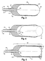
- FIG. 5 Another embodiment of the present invention is shown in Figure 5 .
- the cup unit 60 holds a capsule 50 and contains a highly viscous material 62 at its distal end.
- the combined frictional retention forces emitted by the shell 61 and the material 62 upon the capsule are sufficient to retain the capsule within the shell during the delivery process.
- the expulsion mechanism is the same as previously described.
- Figures 6 and 7 shown yet another embodiment of the present invention.
- Figure 6 is a perspective view of a retention unit 64 constructed of a clear base 40 and a slotted shell 66.
- the shell 66 is molded with an inward bias toward its distal end. The frictional retention forces emitted by the shell 66 are sufficient to retain the capsule within the shell 66 during the delivery process.
- the loading process and expulsion process used in the operation of this embodiment are the same as previously described.
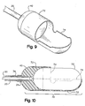
- Figure 8 illustrates a retention unit that includes a clear base 40 and a capsule cup 68.
- the capsule cup 68 is cooperatively shaped and slightly undersized in relation to the capsule 50.
- the capsule cup 68 is constructed of an elastomeric material such as silicon. After manual insertion that stretches the cup, the capsule is held tight within the capsule cup 68 by frictional forces. These forces upon the capsule are sufficient to retain the capsule within the cup 68 during endoscopic delivery of the capsule. The capsule is expelled from the cup 68 by manipulation of the cable 30 as in the previous embodiments.
- FIG. 10 is a side view, partially in section, of the retention unit 70 showing a loaded capsule 50.
- the unit 70 includes a clear base 40 and a molded shell 72.
- the shell in constructed with an irregular-shaped, semi-circumferential orifice 74 at its distal end, through which the capsule 50 will be expelled.
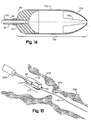
- FIGs 11 and 12 shown yet another embodiment of the present invention.
- the retention unit 80 illustrated includes a clear base 40 and a shell 82.
- Figure 12 is a side view, partially in section, of the retention unit 80 showing a loaded capsule 50.
- the shell is generally bullet shaped and has a tapered distal end. The tapered shape is believed to reduce friction when the endoscope is being intubated to the targeted release point.
- the distal end further includes a series of slots 84 that allow the distal end opening to expand during loading of the capsule 50.
- the retention unit 90 includes a clear base 40 and a hinged shell 92.
- a series of swinging members 94 extend toward the distal end of the shell 92.
- the members 94 are movable about a series of machined or molded hinges 96.
- the loading process and expulsion process used in the operation of this embodiment are the same as previously described.
- the retention unit 100 includes a clear base 40 and a shell 102.
- a plurality of tongues 104 extend from the distal end of the shell 102.
- the tongues are flexible to allow loading and expulsion of a capsule (not shown).
- Figure 15 is a perspective view of yet another embodiment of the present invention.
- the device is shown in use during an endoscopic procedure.
- an endoscope 200 has been intubated into the stomach 202 of a patient.
- the procedure illustrated in Figure 15 is intended to release the capsule 50 beyond the pyloric sphincter 204 into the duodenum 206, i.e., the first portion of the small intestines. If the capsule 50 is expelled into the small intestines at the beginning of image transmission, the odds of recording the entire targeted field before expiration of the battery are increased.
- the retention unit 110 shown has a clear base 40 and a shell 112 that includes a channel 114.
- a guide wire 116 has been threaded through the channel of a dual channel gastroscope 200.
- the guide wire 116 is beneficial in traversing the pyloric sphincter 204.
- the guide wire 116 may be inserted by a single channel standard gastroscope. In this procedure, the scope is then backed out, the capsule is loaded at the distal end of the scope, and the guide wire is inserted in the side channel 114 of the shell. Then, the patient in intubated again.
- Still another alterative technique is the use of a therapeutic gastroscope having a channel large enough for the guide wire 116 and the tube 20 to be threaded together.
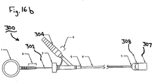
- the capsule may be retained in the retention unit by vacuum forces.
- a device 300 is shown in Figure 16b .
- the device 300 includes a capsule cup 307 and a vacuum cup 308 co-axially disposed therein.
- the capsule cup 307 is cooperatively shaped and oversized in relation to the capsule (not shown).
- the vacuum cup 308 inner surface is sized to engage an end portion of the capsule along a center axis thereof. The capsule is held tight within the vacuum cup 308 by suction forces.
- the vacuum cup 308 is in fluid communication with a suction supply (not shown) applied at an inlet port within the step adapter 304.
- the suction forces upon the capsule are sufficient to retain the capsule within the cups 307, 308 during endoscopic delivery of the capsule.
- the suction forces are removed.
- the capsule is expelled from the cups 307, 308 by manipulation of the cable 302
Landscapes
- Health & Medical Sciences (AREA)
- Life Sciences & Earth Sciences (AREA)
- Surgery (AREA)
- Veterinary Medicine (AREA)
- Biomedical Technology (AREA)
- Public Health (AREA)
- General Health & Medical Sciences (AREA)
- Animal Behavior & Ethology (AREA)
- Biophysics (AREA)
- Heart & Thoracic Surgery (AREA)
- Engineering & Computer Science (AREA)
- Molecular Biology (AREA)
- Physics & Mathematics (AREA)
- Medical Informatics (AREA)
- Pathology (AREA)
- Radiology & Medical Imaging (AREA)
- Optics & Photonics (AREA)
- Nuclear Medicine, Radiotherapy & Molecular Imaging (AREA)
- Gastroenterology & Hepatology (AREA)
- Pulmonology (AREA)
- Anesthesiology (AREA)
- Hematology (AREA)
- Endoscopes (AREA)
- Surgical Instruments (AREA)
- Measurement Of The Respiration, Hearing Ability, Form, And Blood Characteristics Of Living Organisms (AREA)
Applications Claiming Priority (2)
| Application Number | Priority Date | Filing Date | Title |
|---|---|---|---|
| US57407004P | 2004-05-25 | 2004-05-25 | |
| PCT/US2005/018290 WO2005115237A2 (en) | 2004-05-25 | 2005-05-25 | Delivery device |
Publications (3)
| Publication Number | Publication Date |
|---|---|
| EP1765158A2 EP1765158A2 (en) | 2007-03-28 |
| EP1765158A4 EP1765158A4 (en) | 2010-12-22 |
| EP1765158B1 true EP1765158B1 (en) | 2017-08-09 |
Family
ID=35451359
Family Applications (1)
| Application Number | Title | Priority Date | Filing Date |
|---|---|---|---|
| EP05756202.7A Expired - Lifetime EP1765158B1 (en) | 2004-05-25 | 2005-05-25 | Delivery device |
Country Status (4)
| Country | Link |
|---|---|
| US (1) | US8834355B2 (enExample) |
| EP (1) | EP1765158B1 (enExample) |
| JP (1) | JP2008500110A (enExample) |
| WO (1) | WO2005115237A2 (enExample) |
Cited By (1)
| Publication number | Priority date | Publication date | Assignee | Title |
|---|---|---|---|---|
| WO2025224661A1 (en) * | 2024-04-25 | 2025-10-30 | Boston Scientific Medical Device Limited | Medical device for delivery of fluid |
Families Citing this family (29)
| Publication number | Priority date | Publication date | Assignee | Title |
|---|---|---|---|---|
| WO2014082044A1 (en) | 2012-11-26 | 2014-05-30 | Spatz Fgia, Inc. | System and methods for internalization of components of an adjustable intragastric balloon |
| US20060142731A1 (en) * | 2004-12-27 | 2006-06-29 | Jeffrey Brooks | Floating gastro-intestinal anchor |
| US8403952B2 (en) * | 2004-12-27 | 2013-03-26 | Spatz-Fgia, Inc. | Floating gastrointestinal anchor |
| US9974680B2 (en) | 2004-12-27 | 2018-05-22 | Spatz Fgia, Inc. | System and methods for internalization of external components of adjustable intragastric balloon |
| US8235887B2 (en) | 2006-01-23 | 2012-08-07 | Avantis Medical Systems, Inc. | Endoscope assembly with retroscope |
| US8182422B2 (en) | 2005-12-13 | 2012-05-22 | Avantis Medical Systems, Inc. | Endoscope having detachable imaging device and method of using |
| US8797392B2 (en) | 2005-01-05 | 2014-08-05 | Avantis Medical Sytems, Inc. | Endoscope assembly with a polarizing filter |
| US8289381B2 (en) | 2005-01-05 | 2012-10-16 | Avantis Medical Systems, Inc. | Endoscope with an imaging catheter assembly and method of configuring an endoscope |
| US8872906B2 (en) | 2005-01-05 | 2014-10-28 | Avantis Medical Systems, Inc. | Endoscope assembly with a polarizing filter |
| EP2356956A1 (en) * | 2006-03-28 | 2011-08-17 | Spatz-Fgia Inc. | Floating gastrointestinal anchor |
| US8287446B2 (en) | 2006-04-18 | 2012-10-16 | Avantis Medical Systems, Inc. | Vibratory device, endoscope having such a device, method for configuring an endoscope, and method of reducing looping of an endoscope |
| JP2009537283A (ja) | 2006-05-19 | 2009-10-29 | アヴァンティス メディカル システムズ インコーポレイテッド | ビデオアーチファクトの影響を低減するための装置および方法 |
| US8064666B2 (en) | 2007-04-10 | 2011-11-22 | Avantis Medical Systems, Inc. | Method and device for examining or imaging an interior surface of a cavity |
| WO2008132745A2 (en) * | 2007-04-30 | 2008-11-06 | Spatz Fgia, Inc. | Non-endoscopic insertion and removal of a device |
| JP2010035825A (ja) | 2008-08-05 | 2010-02-18 | Olympus Medical Systems Corp | 医療装置 |
| WO2010057082A2 (en) * | 2008-11-17 | 2010-05-20 | Mayo Foundation For Medical Education And Research | Diagnostic capsules, delivery/retrieval systems, kits and methods |
| US20110092998A1 (en) * | 2009-10-13 | 2011-04-21 | Spatz Fgia, Inc. | Balloon hydraulic and gaseous expansion system |
| CN101897573B (zh) * | 2010-09-03 | 2012-05-23 | 吴正奇 | 胶囊内镜推送器 |
| US20140243598A1 (en) * | 2013-02-25 | 2014-08-28 | Corning Incorporated | Optical probe delivery and retrieval systems and methods |
| JP6200627B2 (ja) * | 2013-06-11 | 2017-09-20 | 欣也 藤田 | カプセル内視鏡誘導用処置具 |
| TWI592128B (zh) * | 2016-06-03 | 2017-07-21 | 群曜醫電股份有限公司 | 內視鏡輔助裝置 |
| CN110461408B (zh) | 2017-02-09 | 2022-01-21 | 斯帕茨菲亚有限公司 | 用于胃肠球囊的具有对接站的止回阀 |
| CN109924937B (zh) * | 2018-08-03 | 2024-04-12 | 上海安翰医疗技术有限公司 | 内窥镜装置及内窥检测方法 |
| MX2021007298A (es) | 2018-12-21 | 2021-07-15 | Spatz FGIA Ltd | Valvula con estacion de acoplamiento para globo gastrointestinal. |
| CN114072039B (zh) * | 2019-04-09 | 2025-08-29 | 安克斯机器人公司 | 取液释药系统及方法 |
| USD1060669S1 (en) | 2019-04-09 | 2025-02-04 | AnX Robotica Corp | Tether for a capsule endoscope |
| CN111808916A (zh) | 2020-07-24 | 2020-10-23 | 上海安翰医疗技术有限公司 | 胰蛋白酶检测薄膜及其制备方法、应用和胰蛋白酶检测试剂盒 |
| CN114847847B (zh) * | 2022-04-07 | 2026-03-31 | 中国人民解放军总医院第一医学中心 | 一种胶囊内窥镜输送装置 |
| WO2024017545A1 (en) * | 2022-07-19 | 2024-01-25 | Novo Nordisk A/S | An applicator system and a blister package for the applicator system |
Citations (1)
| Publication number | Priority date | Publication date | Assignee | Title |
|---|---|---|---|---|
| WO2002087657A2 (en) * | 2001-05-01 | 2002-11-07 | Intrapace, Inc. | Gastric device and suction assisted method for implanting a device on a stomach wall |
Family Cites Families (44)
| Publication number | Priority date | Publication date | Assignee | Title |
|---|---|---|---|---|
| US3757781A (en) * | 1971-09-17 | 1973-09-11 | R Smart | Tool for administering pills to animals |
| US3934584A (en) * | 1973-09-26 | 1976-01-27 | Corio Nicholas N | Balling gun |
| JPS5394515A (en) * | 1977-01-31 | 1978-08-18 | Kubota Ltd | Method of producing glass fiber reinforced cement plate |
| US5693083A (en) | 1983-12-09 | 1997-12-02 | Endovascular Technologies, Inc. | Thoracic graft and delivery catheter |
| JPS62164455A (ja) * | 1986-01-16 | 1987-07-21 | 高村 二三知 | 坐剤の投与装置 |
| US4979496A (en) * | 1988-04-05 | 1990-12-25 | Fuji Photo Optical Co., Ltd. | Endoscope for bile duct and pancreatic duct |
| US4936823A (en) * | 1988-05-04 | 1990-06-26 | Triangle Research And Development Corp. | Transendoscopic implant capsule |
| JP3176653B2 (ja) | 1991-07-19 | 2001-06-18 | オリンパス光学工業株式会社 | 医用カプセル装置 |
| CA2123983C (en) * | 1992-09-22 | 1996-07-30 | Thomas J. Palermo | Detachable embolic coil assembly |
| US5350397A (en) * | 1992-11-13 | 1994-09-27 | Target Therapeutics, Inc. | Axially detachable embolic coil assembly |
| US5312415A (en) * | 1992-09-22 | 1994-05-17 | Target Therapeutics, Inc. | Assembly for placement of embolic coils using frictional placement |
| US5259366A (en) * | 1992-11-03 | 1993-11-09 | Boris Reydel | Method of using a catheter-sleeve assembly for an endoscope |
| IL108352A (en) * | 1994-01-17 | 2000-02-29 | Given Imaging Ltd | In vivo video camera system |
| US5653677A (en) * | 1994-04-12 | 1997-08-05 | Fuji Photo Optical Co. Ltd | Electronic endoscope apparatus with imaging unit separable therefrom |
| US5785685A (en) * | 1994-09-16 | 1998-07-28 | Scimed Life Systems, Inc. | Balloon catheter with improved pressure source |
| US5584805A (en) * | 1995-03-17 | 1996-12-17 | Sutton; Matthew R. | Animal pill-dispenser gun |
| US5681279A (en) * | 1996-11-04 | 1997-10-28 | Roper; David H. | Pill dispensing syringe |
| US6071279A (en) * | 1996-12-19 | 2000-06-06 | Ep Technologies, Inc. | Branched structures for supporting multiple electrode elements |
| US6632171B2 (en) * | 1997-12-22 | 2003-10-14 | Given Imaging Ltd. | Method for in vivo delivery of autonomous capsule |
| US8636648B2 (en) * | 1999-03-01 | 2014-01-28 | West View Research, Llc | Endoscopic smart probe |
| EP1175176B1 (en) * | 1999-04-07 | 2010-09-22 | Endonetics, Inc. | Implantable monitoring probe |
| US6285897B1 (en) * | 1999-04-07 | 2001-09-04 | Endonetics, Inc. | Remote physiological monitoring system |
| US6123683A (en) * | 1999-06-22 | 2000-09-26 | Tri-State Hospital Supply Corporation | Pill delivery apparatus |
| JP2001070456A (ja) * | 1999-09-08 | 2001-03-21 | Toru Ubukata | 坐薬入れ器具 |
| JP3797835B2 (ja) * | 1999-11-19 | 2006-07-19 | ユニ・チャーム株式会社 | タンポン用アプリケータ |
| IL147789A0 (en) | 2000-05-23 | 2002-08-14 | Given Imaging Ltd | Device and method for positioning an object in a body lumen |
| EP1399059B1 (en) | 2001-05-18 | 2006-08-30 | Polymer Technology Systems, Inc. | Body fluid test apparatus with detachably mounted portable tester |
| US6814739B2 (en) | 2001-05-18 | 2004-11-09 | U.S. Endoscopy Group, Inc. | Retrieval device |
| US6986738B2 (en) * | 2001-08-06 | 2006-01-17 | Given Imaging Ltd | System and method for maneuvering a device in vivo |
| US6916286B2 (en) * | 2001-08-09 | 2005-07-12 | Smith & Nephew, Inc. | Endoscope with imaging probe |
| US7018346B2 (en) * | 2001-12-18 | 2006-03-28 | Scimed Life Systems, Inc. | Guide wire with adjustable flexibility |
| US7104968B2 (en) * | 2002-06-14 | 2006-09-12 | Mcneil-Ppc, Inc. | Applicator device for suppositories and the like |
| US20040006362A1 (en) * | 2002-07-02 | 2004-01-08 | Dean Schaefer | Uniaxial multifilar vaso-occlusive device with high stretch resistance and low buckling strength |
| US7001329B2 (en) * | 2002-07-23 | 2006-02-21 | Pentax Corporation | Capsule endoscope guidance system, capsule endoscope holder, and capsule endoscope |
| JP4166525B2 (ja) * | 2002-07-23 | 2008-10-15 | Hoya株式会社 | 外部端子を有するカプセル内視鏡およびカプセル内視鏡保持具 |
| US6960183B2 (en) * | 2002-12-02 | 2005-11-01 | Nicolette Jon R | Veterinary pill and capsule delivery device |
| US7351202B2 (en) * | 2002-12-05 | 2008-04-01 | Ethicon Endo-Surgery, Inc. | Medical device with track and method of use |
| US20040153025A1 (en) * | 2003-02-03 | 2004-08-05 | Seifert Paul S. | Systems and methods of de-endothelialization |
| CA2525275C (en) * | 2003-05-16 | 2012-02-07 | C.R. Bard, Inc. | Single intubation, multi-stitch endoscopic suturing system |
| US7654985B2 (en) * | 2004-03-30 | 2010-02-02 | Given Imaging Ltd. | Controlled detachment of intra-luminal medical device |
| US20050245788A1 (en) * | 2004-04-28 | 2005-11-03 | Medtronic, Inc. | Esophageal delivery system and method with position indexing |
| TW200630066A (en) * | 2005-02-23 | 2006-09-01 | Chung Shan Inst Of Science | Disposable two-stage endoscope |
| US20080015413A1 (en) * | 2006-02-22 | 2008-01-17 | Olympus Medical Systems Corporation | Capsule endoscope system and medical procedure |
| JP5023322B2 (ja) | 2006-06-08 | 2012-09-12 | 国立大学法人高知大学 | 縮合多環化合物の製造方法 |
-
2005
- 2005-05-25 JP JP2007515281A patent/JP2008500110A/ja active Pending
- 2005-05-25 US US11/137,525 patent/US8834355B2/en active Active
- 2005-05-25 EP EP05756202.7A patent/EP1765158B1/en not_active Expired - Lifetime
- 2005-05-25 WO PCT/US2005/018290 patent/WO2005115237A2/en not_active Ceased
Patent Citations (1)
| Publication number | Priority date | Publication date | Assignee | Title |
|---|---|---|---|---|
| WO2002087657A2 (en) * | 2001-05-01 | 2002-11-07 | Intrapace, Inc. | Gastric device and suction assisted method for implanting a device on a stomach wall |
Cited By (1)
| Publication number | Priority date | Publication date | Assignee | Title |
|---|---|---|---|---|
| WO2025224661A1 (en) * | 2024-04-25 | 2025-10-30 | Boston Scientific Medical Device Limited | Medical device for delivery of fluid |
Also Published As
| Publication number | Publication date |
|---|---|
| WO2005115237A2 (en) | 2005-12-08 |
| WO2005115237A3 (en) | 2009-04-09 |
| US8834355B2 (en) | 2014-09-16 |
| EP1765158A2 (en) | 2007-03-28 |
| EP1765158A4 (en) | 2010-12-22 |
| US20050267361A1 (en) | 2005-12-01 |
| JP2008500110A (ja) | 2008-01-10 |
Similar Documents
| Publication | Publication Date | Title |
|---|---|---|
| EP1765158B1 (en) | Delivery device | |
| US7959559B2 (en) | Endoscope insertion assisting device, endoscope apparatus, medical treatment device and endoscope insertion method | |
| US6884213B2 (en) | Device and method for positioning an object in a body lumen | |
| KR101849489B1 (ko) | 극세경 내시경 보조 시스템 및 사용 방법 | |
| EP3585319B1 (en) | Deployment catheter comprising markers | |
| US20050038318A1 (en) | Gastrointestinal tool over guidewire | |
| US20120041534A1 (en) | Stent delivery system with integrated camera | |
| JP4665262B2 (ja) | 内視鏡用フード | |
| JPH06105798A (ja) | カテーテルチューブ | |
| JP2010029382A (ja) | 内視鏡挿入補助具及び内視鏡装置 | |
| EP1335662A1 (en) | Sheath and method for reconfiguring lung viewing scope | |
| JP2758349B2 (ja) | カテーテルチューブおよび内視鏡 | |
| US7833176B2 (en) | Pressure-propelled system for body lumen | |
| JP4776317B2 (ja) | 医療用カプセルの保持方法及びそれに用いる内視鏡装置 | |
| BRPI0618682A2 (pt) | cobertura protetora para ferramenta endoscópica | |
| US10524988B2 (en) | Medical tube, and medical tube set | |
| US12533115B2 (en) | Medical delivery devices, assemblies, and related methods | |
| JP4768365B2 (ja) | 内視鏡用の挿入補助具及び内視鏡装置 | |
| CN115844734B (zh) | 一种导丝、导引装置及空肠造瘘系统 | |
| CN219090309U (zh) | 一种导丝、导引装置及空肠造瘘系统 | |
| CN216823384U (zh) | 一种胶囊内窥镜系统 | |
| JP4683282B2 (ja) | 内視鏡装置 | |
| JP7463246B2 (ja) | 内視鏡及び医療機器 | |
| CN113876381B (zh) | 引导组件及包括其的医用吻合器 | |
| JP4710492B2 (ja) | 内視鏡装置 |
Legal Events
| Date | Code | Title | Description |
|---|---|---|---|
| PUAI | Public reference made under article 153(3) epc to a published international application that has entered the european phase |
Free format text: ORIGINAL CODE: 0009012 |
|
| 17P | Request for examination filed |
Effective date: 20061218 |
|
| AK | Designated contracting states |
Kind code of ref document: A2 Designated state(s): AT BE BG CH CY CZ DE DK EE ES FI FR GB GR HU IE IS IT LI LT LU MC NL PL PT RO SE SI SK TR |
|
| AX | Request for extension of the european patent |
Extension state: AL BA HR LV MK YU |
|
| DAX | Request for extension of the european patent (deleted) | ||
| RBV | Designated contracting states (corrected) |
Designated state(s): DE FR GB |
|
| PUAK | Availability of information related to the publication of the international search report |
Free format text: ORIGINAL CODE: 0009015 |
|
| A4 | Supplementary search report drawn up and despatched |
Effective date: 20101118 |
|
| RIC1 | Information provided on ipc code assigned before grant |
Ipc: A61B 1/05 20060101ALI20101112BHEP Ipc: A61B 5/05 20060101AFI20051214BHEP Ipc: A61M 25/01 20060101ALI20101112BHEP Ipc: A61B 5/07 20060101ALI20101112BHEP |
|
| 17Q | First examination report despatched |
Effective date: 20110518 |
|
| REG | Reference to a national code |
Ref country code: DE Ref legal event code: R079 Ref document number: 602005052497 Country of ref document: DE Free format text: PREVIOUS MAIN CLASS: A61B0005050000 Ipc: A61B0001000000 |
|
| GRAP | Despatch of communication of intention to grant a patent |
Free format text: ORIGINAL CODE: EPIDOSNIGR1 |
|
| STAA | Information on the status of an ep patent application or granted ep patent |
Free format text: STATUS: GRANT OF PATENT IS INTENDED |
|
| RIC1 | Information provided on ipc code assigned before grant |
Ipc: A61B 1/04 20060101ALI20170302BHEP Ipc: A61B 1/00 20060101AFI20170302BHEP Ipc: A61B 1/273 20060101ALI20170302BHEP |
|
| INTG | Intention to grant announced |
Effective date: 20170321 |
|
| GRAS | Grant fee paid |
Free format text: ORIGINAL CODE: EPIDOSNIGR3 |
|
| GRAA | (expected) grant |
Free format text: ORIGINAL CODE: 0009210 |
|
| STAA | Information on the status of an ep patent application or granted ep patent |
Free format text: STATUS: THE PATENT HAS BEEN GRANTED |
|
| AK | Designated contracting states |
Kind code of ref document: B1 Designated state(s): DE FR GB |
|
| REG | Reference to a national code |
Ref country code: GB Ref legal event code: FG4D |
|
| REG | Reference to a national code |
Ref country code: DE Ref legal event code: R096 Ref document number: 602005052497 Country of ref document: DE |
|
| REG | Reference to a national code |
Ref country code: DE Ref legal event code: R097 Ref document number: 602005052497 Country of ref document: DE |
|
| REG | Reference to a national code |
Ref country code: FR Ref legal event code: PLFP Year of fee payment: 14 |
|
| PLBE | No opposition filed within time limit |
Free format text: ORIGINAL CODE: 0009261 |
|
| STAA | Information on the status of an ep patent application or granted ep patent |
Free format text: STATUS: NO OPPOSITION FILED WITHIN TIME LIMIT |
|
| 26N | No opposition filed |
Effective date: 20180511 |
|
| P01 | Opt-out of the competence of the unified patent court (upc) registered |
Effective date: 20230513 |
|
| PGFP | Annual fee paid to national office [announced via postgrant information from national office to epo] |
Ref country code: GB Payment date: 20240527 Year of fee payment: 20 |
|
| PGFP | Annual fee paid to national office [announced via postgrant information from national office to epo] |
Ref country code: DE Payment date: 20240530 Year of fee payment: 20 |
|
| PGFP | Annual fee paid to national office [announced via postgrant information from national office to epo] |
Ref country code: FR Payment date: 20240527 Year of fee payment: 20 |
|
| REG | Reference to a national code |
Ref country code: DE Ref legal event code: R071 Ref document number: 602005052497 Country of ref document: DE |
|
| REG | Reference to a national code |
Ref country code: GB Ref legal event code: PE20 Expiry date: 20250524 |
|
| PG25 | Lapsed in a contracting state [announced via postgrant information from national office to epo] |
Ref country code: GB Free format text: LAPSE BECAUSE OF EXPIRATION OF PROTECTION Effective date: 20250524 |