EP1764512A1 - Joint d'étanchéité d'arbre - Google Patents
Joint d'étanchéité d'arbre Download PDFInfo
- Publication number
- EP1764512A1 EP1764512A1 EP05020183A EP05020183A EP1764512A1 EP 1764512 A1 EP1764512 A1 EP 1764512A1 EP 05020183 A EP05020183 A EP 05020183A EP 05020183 A EP05020183 A EP 05020183A EP 1764512 A1 EP1764512 A1 EP 1764512A1
- Authority
- EP
- European Patent Office
- Prior art keywords
- shaft
- seal
- labyrinth seal
- drive
- labyrinth
- Prior art date
- Legal status (The legal status is an assumption and is not a legal conclusion. Google has not performed a legal analysis and makes no representation as to the accuracy of the status listed.)
- Granted
Links
- 238000007789 sealing Methods 0.000 claims abstract description 37
- 239000007788 liquid Substances 0.000 claims abstract description 9
- 239000007789 gas Substances 0.000 claims description 28
- IJGRMHOSHXDMSA-UHFFFAOYSA-N Atomic nitrogen Chemical compound N#N IJGRMHOSHXDMSA-UHFFFAOYSA-N 0.000 claims description 4
- 230000008878 coupling Effects 0.000 claims description 3
- 238000010168 coupling process Methods 0.000 claims description 3
- 238000005859 coupling reaction Methods 0.000 claims description 3
- 230000005540 biological transmission Effects 0.000 claims description 2
- 238000001816 cooling Methods 0.000 claims description 2
- 229910052757 nitrogen Inorganic materials 0.000 claims description 2
- 230000000149 penetrating effect Effects 0.000 claims description 2
- 230000007812 deficiency Effects 0.000 abstract 1
- 239000007787 solid Substances 0.000 description 5
- 231100000331 toxic Toxicity 0.000 description 3
- 230000002588 toxic effect Effects 0.000 description 3
- 230000004888 barrier function Effects 0.000 description 2
- 230000006378 damage Effects 0.000 description 2
- 230000005484 gravity Effects 0.000 description 2
- 238000005461 lubrication Methods 0.000 description 2
- 230000000903 blocking effect Effects 0.000 description 1
- 230000006866 deterioration Effects 0.000 description 1
- 230000008030 elimination Effects 0.000 description 1
- 238000003379 elimination reaction Methods 0.000 description 1
- 239000012530 fluid Substances 0.000 description 1
- 231100001261 hazardous Toxicity 0.000 description 1
- 239000000463 material Substances 0.000 description 1
- 238000012544 monitoring process Methods 0.000 description 1
- 238000010943 off-gassing Methods 0.000 description 1
Images

Classifications
-
- F—MECHANICAL ENGINEERING; LIGHTING; HEATING; WEAPONS; BLASTING
- F04—POSITIVE - DISPLACEMENT MACHINES FOR LIQUIDS; PUMPS FOR LIQUIDS OR ELASTIC FLUIDS
- F04D—NON-POSITIVE-DISPLACEMENT PUMPS
- F04D29/00—Details, component parts, or accessories
- F04D29/08—Sealings
- F04D29/10—Shaft sealings
- F04D29/106—Shaft sealings especially adapted for liquid pumps
- F04D29/108—Shaft sealings especially adapted for liquid pumps the sealing fluid being other than the working liquid or being the working liquid treated
Definitions
- the invention relates to a shaft gap seal for a horizontally disposed driven shaft with drive side and a working side, wherein between the drive side and the working side of a labyrinth seal is provided with a number of grooves.
- double mechanical seals which are lubricated by a harmless medium for the environment, as well as magnetic or canned motors suitable, with magnetic coupled pumps and pumps with canned motor respectively the bearing of the shaft carried out by running in the medium plain bearing and no shaft bushing is present.
- This can also be used for environmentally hazardous media sealing systems has in common that a dry running of the sealing systems or a failure of the lubrication system leads to a strong deterioration of the sealing system to destruction of the same, since the storage is affected by contact with a working fluid with a higher solids content and the containment shell or the can is separated.
- the object of the invention is therefore to avoid the aforementioned disadvantages and to provide a possibility for the Wellenspaltabdichtung a horizontally disposed shaft, which can be used in highly toxic media as well as in media with high solids content and achieved with a high reliability even without extensive monitoring becomes.
- the working side of the particular forming part of a centrifugal pump shaft can be filled with liquid, so that corresponding liquid media can be pumped.
- a circumferential collecting groove for against the sealing gas flow through the labyrinth seal penetrating liquid can be provided, and the collecting groove can via a return line provided on the underside with the region of the working end the labyrinth seal, in particular with the immediate working end of the labyrinth seal, be connected, so that even with a small leakage to the sealing gas flow, which seeps due to gravity at the bottom of the shaft or the labyrinth, so far through the seal passing through the medium Return line to be returned and returned at the working end in the labyrinth seal. This even a leakage of low leakage through the labyrinth seal is avoided.
- the return line may open at a distance of a few grooves in front of the working end of the labyrinth seal, so that a direct contact with the medium located in the working space is avoided. hereby For example, coarser solids located on the working side can not penetrate into the return line, but at most solids that are smaller than the shaft gap.
- a return line may also be provided on the upper side.
- the labyrinth seal may be formed as a comb seal, each with a narrow gap and a large chamber, so that through the narrow gap an accelerated flow is achieved and then in the chamber relaxation occurs.
- an increased pressure loss is effected, so that along the comb seal results in an increased pressure difference.
- the pressure difference between the drive side end on the one hand and the working side, d. H. liquid-side end of the comb seal on the other hand even given unfavorable operating conditions, and improved return transport occurring possibly at the bottom of the labyrinth leakage is achieved.
- shaft seal may be provided which opens at sufficient sealing gas pressure and the sealing gas passes and closes at blocking gas failure, so that at active barrier gas flow through the open sealing lip at most a very low friction between shaft seal and Wave occurs, but prevented in case of failure of the sealing gas flow by closing the shaft sealing ring leakage into the storage area and this protected becomes. With renewed sealing gas supply, the leakage is then returned to the working space.
- the labyrinth of the labyrinth seal can be provided on the shaft, in particular as part of the shaft, so that any solids entrained by the liquid leakage are thrown off there and then transported back to the working side by the barrier gas flow.
- the drive side may be partially provided in a bearing housing and the shaft bushing from the bearing housing to be hermetically sealed by a split pot, wherein a magnetic coupling may be provided for torque transmission, so that there is a hermetic seal by the elimination of a shaft bushing.
- the containment shell is in particular made of a material in which the rotating magnetic field scarcely causes, in particular, no eddy currents whatsoever.
- the drive side may be partially provided in a bearing housing and the shaft passage from the bearing housing to the drive by a gas-locked mechanical seal, in particular single mechanical seal, sealed.
- the gas-lubricated mechanical seal is sufficiently supplied by the sealing gas, and the determination of the sealing gas pressure can be done by the design of the shaft seal, by the pressure loss of the labyrinth seal and by the form of the medium.
- the shaft may be part of a centrifugal pump and the impeller provided with back vanes, so that the pressure in front of the labyrinth is partially or even completely relieved of the pump delivery pressure, so that the required sealing gas pressure, and thus the per unit time required sealing gas quantity is also minimized ,
- the housing enclosing the labyrinth seal can be constructed so that the heat transfer from the working side to the drive side is minimized, and there can be a good otherwise removal of the work-side introduced heat to the environment, for example, by the heat introduced to the environment cooling fins or the like, be ensured, so that even at high operating temperatures can be used.
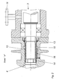
- Fig. 1 shows a centrifugal pump 1 with a horizontally disposed driven shaft 2, which extends between the drive side 3 and the working side 4.
- the drive side 3 is a gas-flushed bearing side and the working side 4 represents the medium side, in particular the liquid side, with a medium inlet 5 and medium outlet 6.
- the drive side 3 is hermetically sealed in the illustrated embodiment and provided with a magnetic coupling 7 with split pot 8.
- the impeller 9 of the centrifugal pump 1 is provided with back vanes 10.
- the sealing gas supply 11 is provided on the upper side on the driven side of the shaft 2.
- the sealing gas introduced through the sealing gas supply 11 flows past the shaft 2 in the direction of the working side 4, wherein it passes through a drive-side shaft sealing ring 13 before entering the labyrinth seal 12.
- the labyrinth seal 12 is in the illustrated embodiment of a arranged on the shaft 2 and with this co-rotating labyrinth 14, a collecting groove 15 in the drive-side region of the labyrinth seal 12 with closing the return line 16, which opens in the working side region of the labyrinth 14 assigned.
Landscapes
- Engineering & Computer Science (AREA)
- Mechanical Engineering (AREA)
- General Engineering & Computer Science (AREA)
- Sealing Using Fluids, Sealing Without Contact, And Removal Of Oil (AREA)
- Structures Of Non-Positive Displacement Pumps (AREA)
- Insulation, Fastening Of Motor, Generator Windings (AREA)
- Sealing Devices (AREA)
Priority Applications (3)
| Application Number | Priority Date | Filing Date | Title |
|---|---|---|---|
| EP05020183A EP1764512B1 (fr) | 2005-09-16 | 2005-09-16 | Joint d'étanchéité d'arbre |
| AT05020183T ATE463674T1 (de) | 2005-09-16 | 2005-09-16 | Wellenspaltabdichtung |
| DE502005009371T DE502005009371D1 (de) | 2005-09-16 | 2005-09-16 | Wellenspaltabdichtung |
Applications Claiming Priority (1)
| Application Number | Priority Date | Filing Date | Title |
|---|---|---|---|
| EP05020183A EP1764512B1 (fr) | 2005-09-16 | 2005-09-16 | Joint d'étanchéité d'arbre |
Publications (2)
| Publication Number | Publication Date |
|---|---|
| EP1764512A1 true EP1764512A1 (fr) | 2007-03-21 |
| EP1764512B1 EP1764512B1 (fr) | 2010-04-07 |
Family
ID=35768440
Family Applications (1)
| Application Number | Title | Priority Date | Filing Date |
|---|---|---|---|
| EP05020183A Active EP1764512B1 (fr) | 2005-09-16 | 2005-09-16 | Joint d'étanchéité d'arbre |
Country Status (3)
| Country | Link |
|---|---|
| EP (1) | EP1764512B1 (fr) |
| AT (1) | ATE463674T1 (fr) |
| DE (1) | DE502005009371D1 (fr) |
Cited By (3)
| Publication number | Priority date | Publication date | Assignee | Title |
|---|---|---|---|---|
| CN105090079A (zh) * | 2014-05-14 | 2015-11-25 | 江苏核电有限公司 | 大型机械密封装配培训与在线检测平台 |
| CN105201898A (zh) * | 2015-10-24 | 2015-12-30 | 车晋绥 | 胶泵新颖水封圈 |
| CN112236006A (zh) * | 2020-10-16 | 2021-01-15 | 安擎(天津)计算机有限公司 | 组合式服务器机架结构及其连接方法 |
Families Citing this family (1)
| Publication number | Priority date | Publication date | Assignee | Title |
|---|---|---|---|---|
| KR102377227B1 (ko) | 2017-03-09 | 2022-03-22 | 존슨 컨트롤스 테크놀러지 컴퍼니 | 백투백 베어링 밀봉 시스템 |
Citations (4)
| Publication number | Priority date | Publication date | Assignee | Title |
|---|---|---|---|---|
| US1867236A (en) * | 1926-05-03 | 1932-07-12 | Bbc Brown Boveri & Cie | Gas sealed gland |
| US2911919A (en) * | 1957-07-23 | 1959-11-10 | C H Wheeler Mfg Co | Pumping system |
| US2959133A (en) * | 1957-09-23 | 1960-11-08 | Allis Chalmers Mfg Co | Hermetically sealed pump motor unit |
| DE1293390B (de) * | 1957-05-28 | 1969-04-24 | Commissariat Energie Atomique | Vorrichtung zur Abdichtung eines zum Verdichten eines aetzenden, schaedlichen und/oder wertvollen Gases dienenden Kreiselkompressors |
-
2005
- 2005-09-16 EP EP05020183A patent/EP1764512B1/fr active Active
- 2005-09-16 DE DE502005009371T patent/DE502005009371D1/de active Active
- 2005-09-16 AT AT05020183T patent/ATE463674T1/de active
Patent Citations (4)
| Publication number | Priority date | Publication date | Assignee | Title |
|---|---|---|---|---|
| US1867236A (en) * | 1926-05-03 | 1932-07-12 | Bbc Brown Boveri & Cie | Gas sealed gland |
| DE1293390B (de) * | 1957-05-28 | 1969-04-24 | Commissariat Energie Atomique | Vorrichtung zur Abdichtung eines zum Verdichten eines aetzenden, schaedlichen und/oder wertvollen Gases dienenden Kreiselkompressors |
| US2911919A (en) * | 1957-07-23 | 1959-11-10 | C H Wheeler Mfg Co | Pumping system |
| US2959133A (en) * | 1957-09-23 | 1960-11-08 | Allis Chalmers Mfg Co | Hermetically sealed pump motor unit |
Cited By (5)
| Publication number | Priority date | Publication date | Assignee | Title |
|---|---|---|---|---|
| CN105090079A (zh) * | 2014-05-14 | 2015-11-25 | 江苏核电有限公司 | 大型机械密封装配培训与在线检测平台 |
| CN105090079B (zh) * | 2014-05-14 | 2018-11-02 | 江苏核电有限公司 | 大型机械密封装配培训与在线检测平台 |
| CN105201898A (zh) * | 2015-10-24 | 2015-12-30 | 车晋绥 | 胶泵新颖水封圈 |
| CN112236006A (zh) * | 2020-10-16 | 2021-01-15 | 安擎(天津)计算机有限公司 | 组合式服务器机架结构及其连接方法 |
| CN112236006B (zh) * | 2020-10-16 | 2022-10-04 | 安擎(天津)计算机有限公司 | 组合式服务器机架结构及其连接方法 |
Also Published As
| Publication number | Publication date |
|---|---|
| DE502005009371D1 (de) | 2010-05-20 |
| ATE463674T1 (de) | 2010-04-15 |
| EP1764512B1 (fr) | 2010-04-07 |
Similar Documents
| Publication | Publication Date | Title |
|---|---|---|
| EP0159464B1 (fr) | Pompe à vide moléculaire | |
| DE1811100C3 (de) | Dichtungsanordnung | |
| EP1893898B1 (fr) | Dispositif d'etancheite radial | |
| DE69719928T2 (de) | Rotationspumpe für Flüssigkeiten | |
| DE102016105309A1 (de) | Magnetkupplungspumpe | |
| EP1764512B1 (fr) | Joint d'étanchéité d'arbre | |
| EP1859171A1 (fr) | Compresseur a injection d'huile et thermocontact | |
| DE102005034341A1 (de) | Tauchmotorpumpe mit Kühlmantel | |
| DE102006058837A1 (de) | Schmiermittelgedichtete Drehschiebervakuumpumpe | |
| DE1653664A1 (de) | Selbstansaugende Zentrifugalpumpe | |
| DE69914389T2 (de) | Dichtungsvorrichtung für Pumpen | |
| EP0459107B1 (fr) | Pompe à vide à palettes et son procédé d'approvisionnement en huile | |
| EP0386315A1 (fr) | Dispositif d'étanchéité et pompe pour son application | |
| DE3701562C2 (de) | Kreiselpumpe mit Spaltrohrmotor | |
| DE19963170A1 (de) | Vakuumpumpe mit Wellendichtmitteln | |
| EP0903500A2 (fr) | Pompe de refroidissement à entraínement électrique | |
| DE19809957A1 (de) | Mehrwellenvakuumpumpe | |
| EP3061974B1 (fr) | Système de refroidissement et de dégazage pour une pompe de transfert de chaleur | |
| EP1211422B1 (fr) | Moteur électrique à rotor noyé pour une pompe | |
| EP0359136A1 (fr) | Pompe centrifuge sans joint, nettoyable | |
| EP2706236B1 (fr) | Pompe avec protection contre la marche à vide | |
| DE202016100655U1 (de) | Magnetkupplungspumpe | |
| WO1998007988A1 (fr) | Machine a faire le vide par voie seche a passage pour arbre | |
| DE342174C (de) | Dichtungsvorrichtung fuer Schleuderpumpen zum Foerdern von Saeuren und anderen aetzenden Fluessigkeiten | |
| DE19812819B4 (de) | Schraubenverdichter mit mechanischer Gleitringwellenabdichtung |
Legal Events
| Date | Code | Title | Description |
|---|---|---|---|
| PUAI | Public reference made under article 153(3) epc to a published international application that has entered the european phase |
Free format text: ORIGINAL CODE: 0009012 |
|
| 17P | Request for examination filed |
Effective date: 20061211 |
|
| AK | Designated contracting states |
Kind code of ref document: A1 Designated state(s): AT BE BG CH CY CZ DE DK EE ES FI FR GB GR HU IE IS IT LI LT LU LV MC NL PL PT RO SE SI SK TR |
|
| AX | Request for extension of the european patent |
Extension state: AL BA HR MK YU |
|
| AKX | Designation fees paid |
Designated state(s): AT BE BG CH CY CZ DE DK EE ES FI FR GB GR HU IE IS IT LI LT LU LV MC NL PL PT RO SE SI SK TR |
|
| 17Q | First examination report despatched |
Effective date: 20080310 |
|
| GRAC | Information related to communication of intention to grant a patent modified |
Free format text: ORIGINAL CODE: EPIDOSCIGR1 |
|
| GRAP | Despatch of communication of intention to grant a patent |
Free format text: ORIGINAL CODE: EPIDOSNIGR1 |
|
| GRAS | Grant fee paid |
Free format text: ORIGINAL CODE: EPIDOSNIGR3 |
|
| GRAA | (expected) grant |
Free format text: ORIGINAL CODE: 0009210 |
|
| AK | Designated contracting states |
Kind code of ref document: B1 Designated state(s): AT BE BG CH CY CZ DE DK EE ES FI FR GB GR HU IE IS IT LI LT LU LV MC NL PL PT RO SE SI SK TR |
|
| REG | Reference to a national code |
Ref country code: GB Ref legal event code: FG4D Free format text: NOT ENGLISH |
|
| REG | Reference to a national code |
Ref country code: CH Ref legal event code: EP |
|
| REG | Reference to a national code |
Ref country code: IE Ref legal event code: FG4D Free format text: LANGUAGE OF EP DOCUMENT: GERMAN |
|
| REF | Corresponds to: |
Ref document number: 502005009371 Country of ref document: DE Date of ref document: 20100520 Kind code of ref document: P |
|
| REG | Reference to a national code |
Ref country code: NL Ref legal event code: VDEP Effective date: 20100407 |
|
| RIN2 | Information on inventor provided after grant (corrected) |
Inventor name: MOELLMANN, HANS W. |
|
| PG25 | Lapsed in a contracting state [announced via postgrant information from national office to epo] |
Ref country code: SI Free format text: LAPSE BECAUSE OF FAILURE TO SUBMIT A TRANSLATION OF THE DESCRIPTION OR TO PAY THE FEE WITHIN THE PRESCRIBED TIME-LIMIT Effective date: 20100407 |
|
| LTIE | Lt: invalidation of european patent or patent extension |
Effective date: 20100407 |
|
| REG | Reference to a national code |
Ref country code: IE Ref legal event code: FD4D |
|
| PG25 | Lapsed in a contracting state [announced via postgrant information from national office to epo] |
Ref country code: ES Free format text: LAPSE BECAUSE OF FAILURE TO SUBMIT A TRANSLATION OF THE DESCRIPTION OR TO PAY THE FEE WITHIN THE PRESCRIBED TIME-LIMIT Effective date: 20100718 Ref country code: SE Free format text: LAPSE BECAUSE OF FAILURE TO SUBMIT A TRANSLATION OF THE DESCRIPTION OR TO PAY THE FEE WITHIN THE PRESCRIBED TIME-LIMIT Effective date: 20100407 Ref country code: NL Free format text: LAPSE BECAUSE OF FAILURE TO SUBMIT A TRANSLATION OF THE DESCRIPTION OR TO PAY THE FEE WITHIN THE PRESCRIBED TIME-LIMIT Effective date: 20100407 Ref country code: LT Free format text: LAPSE BECAUSE OF FAILURE TO SUBMIT A TRANSLATION OF THE DESCRIPTION OR TO PAY THE FEE WITHIN THE PRESCRIBED TIME-LIMIT Effective date: 20100407 |
|
| PGFP | Annual fee paid to national office [announced via postgrant information from national office to epo] |
Ref country code: IE Payment date: 20100916 Year of fee payment: 6 |
|
| PG25 | Lapsed in a contracting state [announced via postgrant information from national office to epo] |
Ref country code: FI Free format text: LAPSE BECAUSE OF FAILURE TO SUBMIT A TRANSLATION OF THE DESCRIPTION OR TO PAY THE FEE WITHIN THE PRESCRIBED TIME-LIMIT Effective date: 20100407 Ref country code: IS Free format text: LAPSE BECAUSE OF FAILURE TO SUBMIT A TRANSLATION OF THE DESCRIPTION OR TO PAY THE FEE WITHIN THE PRESCRIBED TIME-LIMIT Effective date: 20100807 Ref country code: LV Free format text: LAPSE BECAUSE OF FAILURE TO SUBMIT A TRANSLATION OF THE DESCRIPTION OR TO PAY THE FEE WITHIN THE PRESCRIBED TIME-LIMIT Effective date: 20100407 |
|
| PG25 | Lapsed in a contracting state [announced via postgrant information from national office to epo] |
Ref country code: GR Free format text: LAPSE BECAUSE OF FAILURE TO SUBMIT A TRANSLATION OF THE DESCRIPTION OR TO PAY THE FEE WITHIN THE PRESCRIBED TIME-LIMIT Effective date: 20100708 Ref country code: PL Free format text: LAPSE BECAUSE OF FAILURE TO SUBMIT A TRANSLATION OF THE DESCRIPTION OR TO PAY THE FEE WITHIN THE PRESCRIBED TIME-LIMIT Effective date: 20100407 Ref country code: CY Free format text: LAPSE BECAUSE OF FAILURE TO SUBMIT A TRANSLATION OF THE DESCRIPTION OR TO PAY THE FEE WITHIN THE PRESCRIBED TIME-LIMIT Effective date: 20100505 |
|
| PG25 | Lapsed in a contracting state [announced via postgrant information from national office to epo] |
Ref country code: PT Free format text: LAPSE BECAUSE OF FAILURE TO SUBMIT A TRANSLATION OF THE DESCRIPTION OR TO PAY THE FEE WITHIN THE PRESCRIBED TIME-LIMIT Effective date: 20100809 Ref country code: EE Free format text: LAPSE BECAUSE OF FAILURE TO SUBMIT A TRANSLATION OF THE DESCRIPTION OR TO PAY THE FEE WITHIN THE PRESCRIBED TIME-LIMIT Effective date: 20100407 Ref country code: DK Free format text: LAPSE BECAUSE OF FAILURE TO SUBMIT A TRANSLATION OF THE DESCRIPTION OR TO PAY THE FEE WITHIN THE PRESCRIBED TIME-LIMIT Effective date: 20100407 Ref country code: IE Free format text: LAPSE BECAUSE OF FAILURE TO SUBMIT A TRANSLATION OF THE DESCRIPTION OR TO PAY THE FEE WITHIN THE PRESCRIBED TIME-LIMIT Effective date: 20100407 |
|
| PLBE | No opposition filed within time limit |
Free format text: ORIGINAL CODE: 0009261 |
|
| STAA | Information on the status of an ep patent application or granted ep patent |
Free format text: STATUS: NO OPPOSITION FILED WITHIN TIME LIMIT |
|
| PG25 | Lapsed in a contracting state [announced via postgrant information from national office to epo] |
Ref country code: SK Free format text: LAPSE BECAUSE OF FAILURE TO SUBMIT A TRANSLATION OF THE DESCRIPTION OR TO PAY THE FEE WITHIN THE PRESCRIBED TIME-LIMIT Effective date: 20100407 Ref country code: CZ Free format text: LAPSE BECAUSE OF FAILURE TO SUBMIT A TRANSLATION OF THE DESCRIPTION OR TO PAY THE FEE WITHIN THE PRESCRIBED TIME-LIMIT Effective date: 20100407 Ref country code: RO Free format text: LAPSE BECAUSE OF FAILURE TO SUBMIT A TRANSLATION OF THE DESCRIPTION OR TO PAY THE FEE WITHIN THE PRESCRIBED TIME-LIMIT Effective date: 20100407 |
|
| 26N | No opposition filed |
Effective date: 20110110 |
|
| BERE | Be: lapsed |
Owner name: PAUL BUNGARTZ GMBH & CO. K.G. Effective date: 20100930 |
|
| PG25 | Lapsed in a contracting state [announced via postgrant information from national office to epo] |
Ref country code: IT Free format text: LAPSE BECAUSE OF FAILURE TO SUBMIT A TRANSLATION OF THE DESCRIPTION OR TO PAY THE FEE WITHIN THE PRESCRIBED TIME-LIMIT Effective date: 20100407 |
|
| PG25 | Lapsed in a contracting state [announced via postgrant information from national office to epo] |
Ref country code: BE Free format text: LAPSE BECAUSE OF NON-PAYMENT OF DUE FEES Effective date: 20100930 |
|
| PG25 | Lapsed in a contracting state [announced via postgrant information from national office to epo] |
Ref country code: BG Free format text: LAPSE BECAUSE OF FAILURE TO SUBMIT A TRANSLATION OF THE DESCRIPTION OR TO PAY THE FEE WITHIN THE PRESCRIBED TIME-LIMIT Effective date: 20100407 Ref country code: HU Free format text: LAPSE BECAUSE OF FAILURE TO SUBMIT A TRANSLATION OF THE DESCRIPTION OR TO PAY THE FEE WITHIN THE PRESCRIBED TIME-LIMIT Effective date: 20101008 |
|
| PG25 | Lapsed in a contracting state [announced via postgrant information from national office to epo] |
Ref country code: TR Free format text: LAPSE BECAUSE OF FAILURE TO SUBMIT A TRANSLATION OF THE DESCRIPTION OR TO PAY THE FEE WITHIN THE PRESCRIBED TIME-LIMIT Effective date: 20100407 |
|
| PG25 | Lapsed in a contracting state [announced via postgrant information from national office to epo] |
Ref country code: BG Free format text: LAPSE BECAUSE OF FAILURE TO SUBMIT A TRANSLATION OF THE DESCRIPTION OR TO PAY THE FEE WITHIN THE PRESCRIBED TIME-LIMIT Effective date: 20100707 |
|
| REG | Reference to a national code |
Ref country code: FR Ref legal event code: PLFP Year of fee payment: 12 |
|
| REG | Reference to a national code |
Ref country code: FR Ref legal event code: PLFP Year of fee payment: 13 |
|
| REG | Reference to a national code |
Ref country code: FR Ref legal event code: PLFP Year of fee payment: 14 |
|
| PGFP | Annual fee paid to national office [announced via postgrant information from national office to epo] |
Ref country code: MC Payment date: 20230918 Year of fee payment: 19 Ref country code: LU Payment date: 20230918 Year of fee payment: 19 Ref country code: GB Payment date: 20230921 Year of fee payment: 19 Ref country code: AT Payment date: 20230915 Year of fee payment: 19 |
|
| PGFP | Annual fee paid to national office [announced via postgrant information from national office to epo] |
Ref country code: FR Payment date: 20230918 Year of fee payment: 19 Ref country code: DE Payment date: 20230929 Year of fee payment: 19 |
|
| PGFP | Annual fee paid to national office [announced via postgrant information from national office to epo] |
Ref country code: CH Payment date: 20231001 Year of fee payment: 19 |